70
Design of Multifunctional Body Panels for Conflicting Structural and Acoustic Requirements in Automotive Applications CHRISTOPHER J. CAMERON Doctoral Thesis Stockholm, Sweden 2011
Design of Multifunctional Body Panels forConflicting Structural and Acoustic Requirements in
Automotive Applications
CHRISTOPHER J. CAMERON
Doctoral ThesisStockholm, Sweden 2011
TRITA-AVE2011-16ISSN 1651-7660ISBN 978-91-7415-904-2
KTH School of Engineering SciencesDepartment of Aeronautical and Vehicle Engineering
Teknikringen 8SE-100 44 Stockholm
SWEDEN
Akademisk avhandling som med tillstånd av Kungl Tekniska högskolan framlägges till of-fentlig granskning för avläggande av teknologie doktorsexamen i Lättkonstruktioner Tors-dagen den 31 mars 2011, klockan 10:00 i sal F3, Kungliga Tekniska Högskolan, Lindst-edtsvägen 26, Stockholm.
c© Christopher J. Cameron, Feb 2011
Tryck: E-Print AB
iii
Abstract
Over the past century, the automobile has become an integral part of society, with vastincreases in safety, refinement, and complexity, but most unfortunately in mass. Thetrend of increasing mass cannot be maintained in the face of increasingly stringentregulations on fuel consumption and emissions.
The body of work within this thesis exists to help the vehicle industry to take a stepforward in producing vehicles for the future in a sustainable manner in terms of botheconomic and ecological costs. In particular, the fundamentally conflicting require-ments of low weight and high stiffness in a structure which should have good acousticperformance is addressed.
An iterative five step design method based on the concepts of multifunctionality andmultidisciplinary engineering is proposed to address the problem, and explained witha case study.
In the first step of the process, the necessary functional requirements of the systemare evaluated. Focus is placed on the overall system behavior and diverted from sub-problems. For the case study presented, the functional requirements included: struc-tural stiffness for various loading scenarios, mass efficiency, acoustic absorption, vi-brational damping, protecting from the elements, durability of the external surfaces,and elements of styling.
In the second step of the process, the performance requirements of the system wereestablished. This involved a thorough literature survey to establish the state of theart, a rigorous testing program, and an assessment of numerical models and tools toevaluate the performance metrics.
In the third step of the process, a concept to fulfil requirements is proposed. Here, amulti-layered, multi-functional panel using composite materials, and polymer foamswith varying structural and acoustic properties was proposed.
In the fourth step of the process, a method of refinement of the concept is proposed.Numerical tools and parameterized models were used to optimize the three dimensionaltopology of the panel,material properties, and dimensions of the layers in a stepwisemanner to simultaneously address the structural and acoustic performance.
In the fifth and final step of the process, the final result and effectiveness of the methodused to achieve it is examined. Both the tools used and the final result in itself shouldbe examined. In the case study the process is repeated several times with increasingdegrees of complexity and success in achieving the overall design objectives.
In addition to the design method, the concept of a multifunctional body panel is definedand developed and a considerable body of knowledge and understanding is presented.Variations in core topology, materials used, stacking sequence of layers, effects ofperforations, and air gaps within the structure are examined and their effects on per-formance are explored and discussed. The concept shows promise in reducing vehicleweight while maintaining the structural and acoustic performance necessary in the con-text of sustainable vehicle development.

v
Acknowledgements
The work presented in this thesis has been carried out within the Centre for ECO2 VehicleDesign at the Department of Aeronautical and Vehicle Engineering, KTH. The financialsupport provided by Vinnova, KTH, and the industrial partners, in particular Saab Auto-mobile AB, is gratefully acknowledged. Special thanks to Mr. Sven Rahmqvist and Dr.Per-Olof Sturesson from Saab for providing valuable insight and experience from industry.
Many people at KTH have contributed to this thesis in one way of another. To my supervi-sors, Professor Peter Görannson, and Assistant Professor Per Wennhage, I can only humblytip my hat and say thank you for your invaluable guidance, input, and discussions over thepast 4.5 years, and for giving me the opportunity to do my PhD in the first place. It hasbeen one of the most challenging, frustrating, enlightening, enraging, surprising, inspiring,and fulfilling tasks I have ever set out to accomplish. I consider myself fortunate to havebeen given the chance to do it, and thankful that I had such great supervisors!
I would also like to thank Eleonora Lind Nordgren from MWL, who has been an integralpart of a large amount of work performed in the included papers. It has been a pleasureworking with you, and I think that the challenges of working in a collaborative manner haveonly strengthened the value of the work. I would also like to thank Associate ProfessorLeping Feng for his help in the early measurement work.
To everyone in the lightweight structures group, I would also like to extend my thanksfor creating an environment that has made the past 4.5 years fly by and taught me a lot.Specifically I would like to thank Dr. Markus Kaufmann who made the first couple yearsa lot more fun, and Mr. Fredrik Stig who has been a great office mate and ski-buildingpartner......even if he does use a mac.
To my family who has always encouraged and supported me, and constantly wonderedwhen I would be finished with "school", I want to thank you all immensely. You’ve allbeen a source of inspiration and strength at some point.
Finally, I want to thank my wonderful loving wife Camilla, for putting up with me ingeneral, but especially for helping me keep a rough grasp on my sanity through the craziestbits of the trip to creating this little book. Your love and support made this PhD possible.Tack Älskling!
Stockholm, February 2011

vii
Dissertation
This doctoral thesis is based on an introduction to the area of research and the followingappended papers:
Paper I
Christopher J. Cameron, Per Wennhage, and Peter Göransson. Prediction of nvh behav-ior of trimmed body components in the frequency range 100–500hz. Applied Acoustics,71(8):708 – 721, 2010.
Paper II
Christopher J. Cameron, Per Wennhage, Peter Göransson, and Sven Rhamqvist. Structural–acoustic design of a multi–functional sandwich panel in an automotive context. Journal ofSandwich Structures and Materials,12(6):684–708, 2010, doi:10.1177 /1099636209359845.
Paper III
Christopher J. Cameron, Eleonora Lind, Per Wennhage, and Peter Göransson. Proposal ofa methodology for multidisciplinary design of multifunctional vehicle structures includingan acoustic sensitivity study. Int.J. Vehicle Structures & Systems, (1–3):1–13, 2009.
Paper IV
Christopher J. Cameron, Eleonora Lind Nordgren, Per Wennhage, and Peter Göransson.Material Property Steered Structural and Acoustic Optimization of a Multifunctional Ve-hicle Body Panel. Manuscript, submitted to ASME Journal of Mechanical Design.
viii
Paper V
Christopher J. Cameron, Eleonora Lind Nordgren, Per Wennhage, and Peter Göransson. ADesign Method using Topology, Property, and Size Optimization to Balance Structural andAcoustic Performance of Sandwich Panels for Vehicle Applications. Manuscript, submit-ted to Computers and Structures
Portions of this thesis have also been presented as follows:
Christopher J. Cameron, Per Wennhage, Peter Göransson, and Sven Rhamqvist. Structural-Acoustic Design of a Multi-Functional Body Panel for Automotive Applications, In Pro-ceedings of the 8th International Conference on Sandwich Structures (ICSS8), Porto, Por-tugul, 6-8 May 2008.
Christopher J. Cameron, Eleonora Lind, Per Wennhage, and Peter Göransson, MaterialProperty Steered Optimization of a Multifunctional Body Panel to Structural and AcousticConstraints, In Proceedings of ICCM-17, 17th International Conference on CompositeMaterials, Edinburgh, Scotland, 27-31 July 2009.
Christopher J. Cameron, Per Wennhage, and Peter Göransson. Multi-Scale StructuralAcoustic Optimization of a Multi-Functional Vehicle Body Panel. In Proceedings of theTwenty Second Nordic Seminar on Computational Mechanics, Aalborg, Denmark, 22-23October 2009.
Christopher J. Cameron, Eleonora Lind Nordgren, Per Wennhage, and Peter Göransson.Balancing Structural and Acoustic Performance of Sandwich Panels for Vehicle Applica-tions with Topology, Property, and Size Optimization. In Proceedings of ACCM 7, TheSeventh Asian-Australasian Conference on Composite Materials. 15-18 November 2010.
Contents
I Introduction 1
1 Background and Context 31.1 Historical Vehicle Development Trends . . . . . . . . . . . . . . . . . . 3
2 Vehicle Form and Functionality 62.1 Vehicle Structures . . . . . . . . . . . . . . . . . . . . . . . . . . . . . . 62.2 Noise Vibration and Harshness . . . . . . . . . . . . . . . . . . . . . . . 72.3 Alternative Materials . . . . . . . . . . . . . . . . . . . . . . . . . . . . 8
3 Tools for Vehicle Design 123.1 Structural Design . . . . . . . . . . . . . . . . . . . . . . . . . . . . . . 123.2 NVH tools and methods . . . . . . . . . . . . . . . . . . . . . . . . . . . 123.3 Optimization . . . . . . . . . . . . . . . . . . . . . . . . . . . . . . . . 13
4 The Multifunctional and Multidisciplinary Design Paradigm 164.1 An Iterative Design Process . . . . . . . . . . . . . . . . . . . . . . . . . 164.2 The Case Study . . . . . . . . . . . . . . . . . . . . . . . . . . . . . . . 19
5 Conclusions and Summary 50
6 Future Work 53
Bibliography 54
II Appended papers 61
ix


Part I
Introduction
1

Introduction 3
1 Background and Context
1.1 Historical Vehicle Development Trends
The automobile has come a long way since 1886 when Karl Benz filed a patent for a vehiclewith gas powered drive. Henry Ford brought the car to the general public with the model Tand the concept of mass production. While different manufacturers would likely disagreeas to what is the single most important quality in producing a vehicle, it is likely they wouldall agree that a policy of continuous development of ones products is an absolute necessity.
Continuous improvement of areas such as safety, comfort, handling, performance, and evenconvenience, have not been achieved without a certain cost. Perhaps the most tangible costis the growing mass of the vehicles produced. Table 1.1 shows some historical data onvehicle curb weights from a single manufacturer, Saab Automobile, obtained from variousunofficial sources, [1, 2, 3]. This trend of constantly increasing vehicle mass and size isby no means limited to a single manufacturer, but is in fact a global trend. While the oilcrisis of the 1970’s had a short lived impact on vehicle weight, it’s increase has continuedunabated since the 1980’s, at approximately 1.2 % per annum since 1985, [4, 5].
Today’s automobile manufacturers are keenly aware of the challenges facing the automo-tive industry in the near future. In order to try and achieve some of the mass reductionsthat will be necessary, manufacturers have already been trying to find areas of obviousmass inefficiency.
Standard grades of low-carbon steel were for many years the norm in vehicle productionbecause they were relatively cheap, formable, weldable, and show a reasonably predictabledeformation behavior in a crash scenario. Replacing low-carbon steel with high strengthsteel, which has a much higher strain to failure and thus can be made thinner, is one methodof saving weight which has been well documented within the industry, and has the weightof the steel producing industry behind it, [6, 7, 8].

4 Christopher J. Cameron
Table 1: Unofficial Vehicle Curb Weights of Saab cars 1950-2008
Model Year Model Name Curb Weight
1950-52 Saab 93 805 kg1956-58 Saab 93 810 kg1959-66 Saab 95 905 kg1966 Saab 96v4 946 kg1969-84 Saab 99 955 kg1976 Saab 99EMS 1161 kg1979-93 Saab 900 1174 kg1984 Saab 900Turbo 1340 kg1986 Saab 9000i 1280 kg1985-98 Saab 9000 1302 kg1988 Saab 900i 1285 kg1999 Saab 9-3 1305 kg2001 Saab 9-3Viggen 1438 kg2004 Saab 9-3 1.8i 1440 kg2008 Saab 9-3 1400-1600 kg2010 Saab 9-3 1530-1680 kg
A Larger Step to Conceptual Change
That reduced emissions and fuel consumption are directly coupled to the mass of the ve-hicle is a well understood fact, however the exact magnitudes of such reductions are onlymore recently being understood, [9]. There exist significant opportunities to reduce unnec-essary mass in existing vehicles and those of the near future, [10], and thus reduce theirburden in terms of emissions and fiscal resources. The future of the automotive industry,after all the obvious changes are made, is however much more uncertain. Assuming thatregulations regarding emissions, fuel consumption, safety, etc will continue to increase instringency as they have without exception historically (if in some cases rather slowly suchas in fuel economy in the U.S., [4, 5]) it is rather clear that the automotive industry willhave to do something more than swap out mild steel for high strength steel and aluminium,should it survive and turn a profit.
The body of work within this thesis has one primary objective: to help the vehicle industryto take a larger step forward in creating the vehicles we will need within the not so distantfuture. That the passenger car is an integrated part of our lives and of growing impor-tance to developing economies, [11], is understandable as is the simple fact that it is hereto stay. Knowing that, we need to be able to produce vehicles in a sustainable manner,in terms of both economic and ecological costs. This concept of achieving sustainabledevelopment is the driving philosophical argument for performing the research presentedin this thesis, and the foundation of the Centre for ECO2 Vehicle Design. By combining
Introduction 5
the collective knowledge and experience of vehicle manufacturers in different segments ofthe transportation industry with the unconstrained ability of academia to explore unprovenmethods and non-conventional solutions, new synergies and solution strategies combiningareas of conventional wisdom traditionally seen as separate entities can be obtained. It is inthis spirit that the work presented in this thesis has been performed, and which the authorhas attempted to convey in the pages which follow.
To understand the concepts and methods proposed herein, it is necessary that the reader un-derstand the two primary areas of vehicle engineering involved; namely vehicle structuresand vehicle acoustics. In addition, some familiarity with certain materials and tools whichare referred to, i.e. sandwich structures, composite materials, and numerical optimizationis also required. A brief introduction to these topics is presented herein. To avoid excessiverepetition, the introduction will be kept rather short, and the reader is instead encouragedto examine the accompanying articles or the vast body of external literature on the topicsdiscussed.
6 Christopher J. Cameron
2 Vehicle Form and Functionality
2.1 Vehicle Structures
That a modern passenger car looks the way it does is not merely the result of coincidence,or purely an exercise in styling. Certain functionalities are required to achieve an efficientform of transportation, that is among other things; safe, comfortable, reliable, and aesthet-ically pleasing. The drive train, which propels the vehicle forward, needs to be coupled tothe suspension and steering systems, which promote the transfer of tractive forces betweenthe wheels and the road and control its direction. The perceived driving behavior, i.e. turn-ing response, sportiness, etc, is directly effected by how these systems are coupled. Otherforces, such as inertial forces encountered during crash, need to be accommodated in amanner that protects the occupants. Seats, doors, and trim details need a support to whichthey can be attached, and passengers should be protected from the elements. In the contextof the present work, these functions are realised through the vehicle’s body structure.
The historical praxis within the automotive industry to accomplish such a structure hasbeen to spot weld together a large number of pressed steel or aluminium components. Thisassembly, having been coated with a primer prior to being painted, is commonly known asthe body in white (BIW). Within the BIW, a significant amount of functional specializationis present. Large sheet metal panels, which in some cases do contribute somewhat to thestiffness of the BIW, are primarily for exterior styling. Underneath these exterior panelsare various open and close formed sheet metal profiles to support normal driving loads orto protect the occupants during a crash. Requirements are placed on characteristics suchas bending stiffness and torsional stiffness of the BIW to ensure favourable performanceand handling. Crash safety, i.e. controlling the modes and degree to which a BIW deformsduring various forms of impact, is perhaps the single most important factor involved in thedetailed design of the BIW, which often leads to conflicts with other vehicle functions.
While the alarming trends mentioned in the previous chapter may lead one to draw otherconclusions, structural mass is in fact a very high priority and vehicle manufacturers spendsignificant time, effort, and money on reducing it as much as possible. Herein however, liesthe fundamentally antagonistic requirements which this work sets out to address; structureswhich are required to be lightweight and stiff will, by their very nature, vibrate when
Introduction 7
subjected to stochastic or frequency dependent forces such as a cobblestone road, or anengine running at varying RPM. This phenomena has in fact led to the development of anentire subcategory of vehicle engineering.
2.2 Noise Vibration and Harshness
Noise, Vibration and Harshness, more commonly known as NVH, is an all encompassingengineering discipline that deals with the objective and subjective structural dynamic andacoustic aspects of automobile design. For reasons of comfort, quality, safety, and reliabil-ity among others, NVH engineers are focused on predicting, and controlling or eliminatingsound and vibration phenomena within the vehicle.
NVH problems are dynamic by nature, and thus are frequency related. One generally refersto noise as being audible sounds in the frequency range from 30-4000 Hz, and vibration asthe mechanical vibration in the frequency range 30-200 Hz, [12]. The three main sourcesof interior noise are the engine and accessories, tyre/road interaction, and airflow overthe external bodywork (wind noise), [13]. Further, one can make the distinction betweenairborne sound, which is of higher frequencies, and structure borne sound, which is in thelower frequencies. From the perspective of a typical occupant, this distinction might not beso clear, however from the perspective of the NVH engineer, the methods and tools usedto deal with them differ significantly.
Airborne Sound
Airborne sound often originates from external sources and propagates into the vehicle in-terior via holes in the bodywork, door seals, weld seams, etc, [12]. Its contribution tointerior sound pressure levels is predominantly in the higher frequency ranges. Controllingairborne sound can be done by eliminating the source of the sound (if possible), or elimi-nating the transfer paths into the vehicle. Sound pressure waves propagate along the path ofleast resistance, and commonplace solutions such as acoustic baffles, urethane filler foams,rubber plugs and grommets, and adhesive seam sealants are used to impede an airbornesound propagating into the passenger compartment, [14]. The implementation of thesesorts of solutions rely heavily on testing, and experience of the engineers involved. Con-trolling sound levels inside the compartment is often done with different types of acoustictrim treatments that can offer varying levels of insulation or absorption.
Structure Borne Sound
Structure borne sound is the result of mechanical vibrations propagating through the ve-hicle structure and eventually causing localised displacements of air. Sound levels due tovibration can be directly related to the volume of air which is displaced. A 1 cm3 volume
8 Christopher J. Cameron
displacement, which could be achieved by a 1 m2 area of roof vibrating with a displacementamplitude of 1 µm, can cause a sound pressure of 75 dB in a vehicle interior, [15]. Muchof the noise in the frequency range up to 500 Hz is caused by cavity resonances which maybe excited by vibrations of the BIW caused by suspension or drivetrain inputs. The termbooming noise is often used to describe such acoustic phenomena in the frequency rangebelow 250 Hz. Body vibration levels are directly related to the road roughness, vehiclespeed, suspension characteristics etc. For a more complete explanation of the phenomenaof structure borne noise in general, the interested reader is directed to the literature, [16].
2.3 Alternative Materials
While sheet metal structures offer excellent performance in terms of, among other things,cost, predictable deformation under impact, and recycleability, they do have negative as-pects such as a tendency to corrode, and to be a veritable bonanza of vibratory and acousticphenomena. Sheet metal is however not the only potential candidate for structural design inmodern vehicles. Such material concepts as fibre-reinforced plastics and sandwich struc-tures have long been discussed in the periphery of vehicle design. For various reasons,they have not made a significant contribution to the structural composition of mass pro-duced modern vehicles. Nevertheless, as the need for a conceptual change surmounts thechallenges of implementing such concepts in production, they are likely to become morecommon in future generations of vehicles. For the purposes of informing the unfamiliarreader, a brief introduction to these two material system concepts is given.
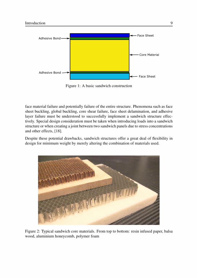
The Basic Sandwich Structure
Figure 1 shows the most basic form of a structural sandwich. Two thin face sheets of stiffand strong material are attached to a softer and weaker core material to achieve a sumgreater than its parts. By separating the two face sheets with a lightweight material, onecan significantly increase the bending stiffness, or flexural rigidity, without significantlyaffecting the weight. This phenomena, commonly referred to as the sandwich effect, isonly valid assuming that the face sheets are much stiffer, thinner, and denser than thecore material. Mechanically, the face sheet layers take up the applied bending loads andmoments as tensile and compressive stresses while the core material carries transverseloading predominantly as shear. For an in depth explanation of sandwich structure theoryand technology, the reader is referred to the literature, [17].
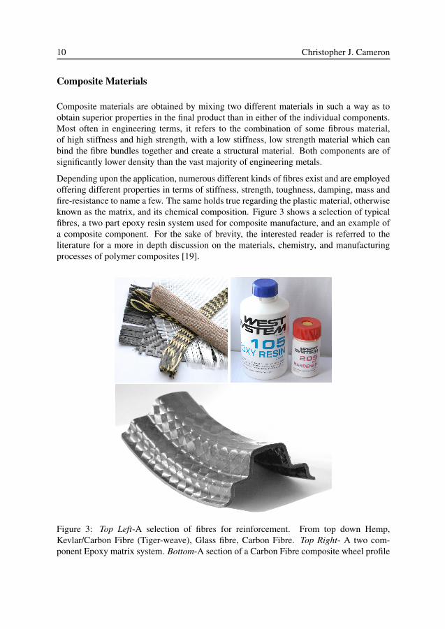
Metals or fibre reinforced composites are by far the most common materials used for facesheets. A vast array of materials can be used in the core, but perhaps the most commonare expanded polymer foams, honeycombs of aluminium or paper, or balsa wood, all ofwhich can be seen in figure 2. While rather robust, and exceptionally weight effective atcarrying loads in bending, sandwich structures are not suited to all types of applications.Concentrated out of plane loading should generally be avoided as it can lead to core or
Introduction 9
Figure 1: A basic sandwich construction
face material failure and potentially failure of the entire structure. Phenomena such as facesheet buckling, global buckling, core shear failure, face sheet delamination, and adhesivelayer failure must be understood to successfully implement a sandwich structure effec-tively. Special design consideration must be taken when introducing loads into a sandwichstructure or when creating a joint between two sandwich panels due to stress concentrationsand other effects, [18].
Despite these potential drawbacks, sandwich structures offer a great deal of flexibility indesign for minimum weight by merely altering the combination of materials used.
Figure 2: Typical sandwich core materials. From top to bottom: resin infused paper, balsawood, aluminium honeycomb, polymer foam
10 Christopher J. Cameron
Composite Materials
Composite materials are obtained by mixing two different materials in such a way as toobtain superior properties in the final product than in either of the individual components.Most often in engineering terms, it refers to the combination of some fibrous material,of high stiffness and high strength, with a low stiffness, low strength material which canbind the fibre bundles together and create a structural material. Both components are ofsignificantly lower density than the vast majority of engineering metals.
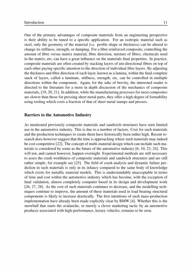
Depending upon the application, numerous different kinds of fibres exist and are employedoffering different properties in terms of stiffness, strength, toughness, damping, mass andfire-resistance to name a few. The same holds true regarding the plastic material, otherwiseknown as the matrix, and its chemical composition. Figure 3 shows a selection of typicalfibres, a two part epoxy resin system used for composite manufacture, and an example ofa composite component. For the sake of brevity, the interested reader is referred to theliterature for a more in depth discussion on the materials, chemistry, and manufacturingprocesses of polymer composites [19].
Figure 3: Top Left-A selection of fibres for reinforcement. From top down Hemp,Kevlar/Carbon Fibre (Tiger-weave), Glass fibre, Carbon Fibre. Top Right- A two com-ponent Epoxy matrix system. Bottom-A section of a Carbon Fibre composite wheel profile
Introduction 11
One of the primary advantages of composite materials from an engineering perspectiveis their ability to be tuned to a specific application. For an isotropic material such assteel, only the geometry of the material (i.e. profile shape or thickness) can be altered tochange its stiffness, strength, or damping. For a fibre reinforced composite, controlling theamount of fibre versus matrix material, fibre direction, mixture of fibres, chemicals usedin the matrix, etc, can have a great influence on the materials final properties. In practice,composite materials are often created by stacking layers of uni-directional fibres on top ofeach other paying specific attention to the direction of individual fibre layers. By adjustingthe thickness and fibre direction of each layer, known as a lamina, within the final completestack of layers, called a laminate, stiffness, strength, etc, can be controlled in multipledirections within the component. Again, for the sake of brevity, the interested reader isdirected to the literature for a more in depth discussion of the mechanics of compositematerials, [19, 20, 21]. In addition, while the manufacturing processes for most compositesare slower than those for pressing sheet metal parts, they offer a high degree of formabilityusing tooling which costs a fraction of that of sheet metal stamps and presses.
Barriers to the Automotive Industry
As mentioned previously composite materials and sandwich structures have seen limiteduse in the automotive industry. This is due to a number of factors. Cost for such materialsand the production techniques to create them have historically been rather high. Recent re-search does however suggest that the time is approaching where such materials may indeedbe cost competitive [22]. The concept of multi-material design which can include such ma-terials is considered by some as the future of the automotive industry [6, 10, 23, 24]. Thiswill not, and cannot however, happen overnight. Experimental methods are still necessaryto asses the crash worthiness of composite materials and sandwich structures and are stillrather simple, for example see [25]. The field of crash analysis and dynamic failure pre-diction in such materials is only in its infancy compared to the same body of knowledgewhich exists for metallic material models. This is understandably unacceptable in termsof time and cost within the automotive industry which has become, with the exception offinal validation, almost completely computer based in its design and development work[26, 27, 28]. As the cost of such materials continues to decrease, and the modelling tech-niques continue to improve, the amount of these materials used in load bearing structuralcomponents is likely to increase drastically. The first intentions of such mass-productionimplementation have already been made explicitly clear by BMW [4]. Whether this is thesnowball that starts the avalanche, or merely a clever marketing tactic by an automotiveproducer associated with high-performance, luxury vehicles, remains to be seen.
12 Christopher J. Cameron
3 Tools for Vehicle Design
3.1 Structural Design
Nearly all structural design of modern vehicles is done using computer aided engineer-ing tools. Finite element analysis (FEA), in various different formulations, constitutes asignificant portion of the numerical analysis within the automotive industry. It also formsthe basic foundation of the design methods discussed within this thesis. It is assumedthat the reader has a working knowledge of such methods, which have been elegantlyand thoroughly derived and explained in numerous textbooks on the subject, for example[29, 30, 31, 32] and will therefore be excluded from the current text.
Such numerical tools are advantageous to the structural design process because they areaccurate, consistent, repeatable, and save time and money by eliminating some of the needfor testing and prototypes. Perhaps most importantly for the context of this thesis, thesemethods lend themselves well to the concept of optimization. The ability to quickly andaccurately gain an understanding of how a small change to a structural component canchange its behavior is critical to achieving a successful design with minimal time andresources.
3.2 NVH tools and methods
Historically, the prediction and control of sound and vibration has been a manpower inten-sive process of "test-analyse-fix" [33] as vehicle refinement often takes place in the finalstages of production. This policy precludes the possibility for NVH engineers to activelyavoid designs which are prone to problems, and rather forces them to take on the mantle ofthe crisis management team.
A significant amount of NVH testing goes towards predicting which portions of the BIWare going to vibrate the most, and thus potentially be the largest source of unwanted sound.Proposals for improvements of such procedures and test methods are numerous in the lit-erature, [34, 35, 36, 37]. By far, the most common method of addressing such vibratoryproblems, is with the use of viscoelastic damping layers, [38], also known as deadeners,
Introduction 13
which are effective, but rather weight inefficient, and sometimes costly. Developing a pre-dictive tool to eliminate the need for such a high level of testing has been a goal on thehorizon for many years and has led to many proposed solutions, [39, 40, 41, 42, 43, 44].For a more detailed survey of the methods explored, the reader is directed the literature,[13].
In addition to panel damping treatments, a great deal of work goes into selecting interiortrim to provide acoustic functionality. While this has also historically been a test and ex-perience driven exercise, in recent years the numerical tools for studying trimmed bodybehavior have grown tremendously. When the work in this thesis began, very little wasavailable in the published literature, however now the list abounds with researchers explor-ing methods like finite element analysis of porous materials and statistical energy analysis(SEA) or hybrid methods of the two, [45, 46, 47, 48, 49, 50, 51, 52]. These methods areeffective, however they often require large amounts of computational time. This is par-tially due to the necessary use of a fluid cavity in addition to the actual models of the trimcomponents within the finite element model, which must be coupled to the structure and toeach other and greatly increases the number of degrees of freedom to be solved for, and thecomplexity of the solution type. For a more detailed discussion of such topics, the readeris again directed to the literature, [15, 53].
Perhaps the largest problem in developing effective and consistent NVH solutions, is thevariability within the problem itself. Due to the huge number of processes involved inassembly, and the large number of options available within a manufacturers model fam-ily, no two individual vehicles will have the exact same NVH behavior in the frequencyrange of interest, and thus any "ideal" solution achieved will in fact only be "ideal" for thegiven vehicle in question [54, 55, 56]. This does not however make the process in iden-tifying and quantifying the dominating mechanisms for response an exercise in futility.On the contrary, appropriate estimates of behavior are highly valuable, whereas extremelyprecise results obtained at great expense of time and money may be superfluous or evenun-useable. This is obviously a question of balance which is still in its infancy. The keylies in incorporating the "neccesary" physical phenomena, rendering further analysis andsubsequent conclusions viable.
3.3 Optimization
Optimization, in an engineering design context, refers to an iterative process in which anequation or set of equations is solved to minimise(or maximise) a certain quantity whichis dependant upon one or more variables chosen by the user. The basis for successfullysolving an optimization problem is some form of mathematical expression of the quantityto be optimized, commonly known as the objective function, which may or may not beknown explicitly from the outset. The unknowns, or design variables, are changed by theoptimization algorithm in order to achieve a best possible value of the objective function.A certain degree of control over the problem can be obtained by placing constraints on
14 Christopher J. Cameron
certain parameters, such as the region of validity of the design variables, or the numericalvalue of output from a portion of the system of equations. Equation 3.3 shows the mostbasic form of optimization problem where f(x) is the objective function, x1 and x2 are thedesign variables, and the inequalities for G(x) represent the constraints.
minimize f(x) = x1 + x2
subject to:G(x1) ≥ aG(x2) ≥ b (1)
Methods and algorithms for solving such problems are numerous, and the body of theoryand knowledge in this subject is immense. Depending on the size and complexity of theproblem, it might be possible to solve with pen and paper, or require extended computa-tional time on high performance computer clusters. Furthermore, for any given optimalsolution, the question of robustness, i.e. certainty in that the solution is in fact a globaloptima and not merely a local optima, must be properly addressed. Within this work, twodistinctly different methods of optimization have been employed, namely a gradient basedoptimization method known as the method of moving asymptotes (MMA), [57, 58], andthe topology optimization algorithm known as bi-directional evolutionary structural opti-mization (BESO), [59, 60]. For a more detailed discussion of general optimization theorythe reader is again directed to the literature, [61].
Gradient Based Optimization
Gradient based optimization tools, of which MMA is only one of many, are based on theconcept that while the explicit definition of the objective function at hand might be un-known, i.e. implicit, by evaluating the problem multiple times using small perturbations ofthe design variables an approximation of the function can be obtained. This approximationcan be used then to choose the direction of change of the design variables to achieve animprovement in the objective function.
Such an algorithm is highly effective in certain cases, like for example mass optimizationof a truss structure using thickness of its members as design variables. In such a case,constraints might be placed upon the minimum thickness of certain members, or the maxi-mum displacement of the truss for a given loading condition. These algorithms are almostalways implemented together with some form of numerical tool to solve the objective func-tion rapidly. In the context of this thesis, FEA is used exclusively.
Gradient based methods are highly effective, however they have limitations in terms of thenumber of permissible design variables and size of the model to be solved. As each variablewill require at least one perturbation analysis per iteration, excessive numbers of variablesor excessively long solve times for the model can effectively prohibit the use of such al-
Introduction 15
gorithms. This is a fact known within the automotive industry in terms of optimizationfor crash computations. Here, statistical based methods may be more appropriate, [62].In addition, for the present work which focusses in part on the dynamics of the systemsbehavior, the influence of resonances in various sub-systems adds further complication.
As previously mentioned, MMA, [57], including recent improvements in the algorithmregarding global convergence, [58], have been the only gradient based algorithm used inthe optimization performed in this work. This algorithm was chosen as it is well known andregarded within the literature, efficient, effective, and implemented in available computercode in several different forms.
Topology Optimization
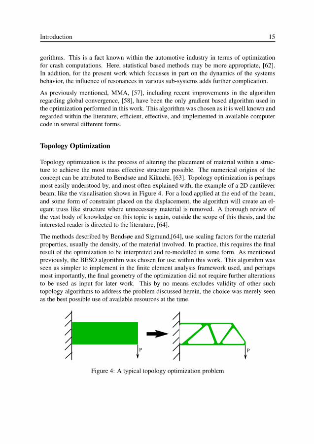
Topology optimization is the process of altering the placement of material within a struc-ture to achieve the most mass effective structure possible. The numerical origins of theconcept can be attributed to Bendsøe and Kikuchi, [63]. Topology optimization is perhapsmost easily understood by, and most often explained with, the example of a 2D cantileverbeam, like the visualisation shown in Figure 4. For a load applied at the end of the beam,and some form of constraint placed on the displacement, the algorithm will create an el-egant truss like structure where unnecessary material is removed. A thorough review ofthe vast body of knowledge on this topic is again, outside the scope of this thesis, and theinterested reader is directed to the literature, [64].
The methods described by Bendsøe and Sigmund,[64], use scaling factors for the materialproperties, usually the density, of the material involved. In practice, this requires the finalresult of the optimization to be interpreted and re-modelled in some form. As mentionedpreviously, the BESO algorithm was chosen for use within this work. This algorithm wasseen as simpler to implement in the finite element analysis framework used, and perhapsmost importantly, the final geometry of the optimization did not require further alterationsto be used as input for later work. This by no means excludes validity of other suchtopology algorithms to address the problem discussed herein, the choice was merely seenas the best possible use of available resources at the time.
Figure 4: A typical topology optimization problem
16 Christopher J. Cameron
4 The Multifunctional andMultidisciplinary Design Paradigm
The previous chapters within this thesis have given the reader a background of informationnecessary to understand the central topic of the work, i.e. multidisciplinary and multifunc-tional design.
The research work leading to this thesis forms a synthesis between design of a structurallyviable component and its acoustic performance in an automotive setting. The paradigmused is multifunctionality, i.e. designing an integrated component with desired acousticand structural performance at a low weight. The central focus of the work has been findingmethods to balance the strongly conflicting requirements of a high stiffness, low weightstructure with a comfortable, low noise acoustic environment within the vehicle. The re-sulting methodology developed and the tools used will be presented and explained in amanner which gives context, perspective and hopefully a higher level of understanding ofthe detailed body of results included in the appended papers.
4.1 An Iterative Design Process
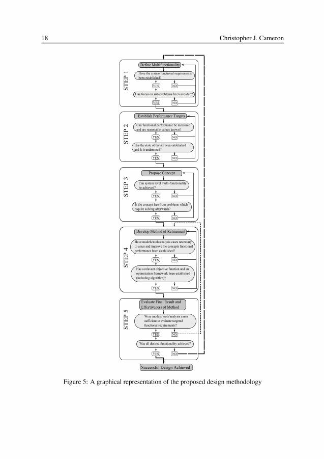
Figure 5 gives a graphical representation of the proposed design process to successfullyachieve a design which is both multidisciplinary, and multifunctional. From first observa-tion, it is obvious that the process is iterative in nature, and has several levels of feedbackfrom the later stages of design to the earlier stages acting as the check points of the pro-cess. While chronologically speaking, this methodology in its current form appears first inpaper III, from a retrospective viewpoint the author nevertheless feels it is appropriate, andprudent, to begin the discussion at this point.
The proposed design methodology consists of the following five steps:
1. Define the multifunctionality2. Establish performance targets3. Propose concept to fulfil requirements
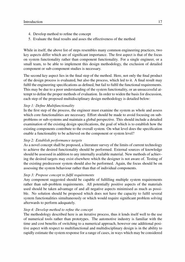
Introduction 17
4. Develop method to refine the concept5. Evaluate the final results and asses the effectiveness of the method
While in itself, the above list of steps resembles many common engineering practices, twokey aspects differ which are of significant importance. The first aspect is that of the focuson system functionality rather than component functionality. For a single engineer, or asmall team, to be able to implement this design methodology, the exclusion of detailedcomponent or sub-component studies is necessary.
The second key aspect lies in the final step of the method. Here, not only the final productof the design process is evaluated, but also the process, which led to it. A final result mayfulfil the engineering specifications as defined, but fail to fulfil the functional requirements.This may be due to a poor understanding of the system functionality, or an unsuccessful at-tempt to define the proper methods of evaluation. In order to widen the basis for discussion,each step of the proposed multidisciplinary design methodology is detailed below:
Step 1: Define MultifunctionalityIn the first step of the process, the engineer must examine the system as whole and assesswhich core functionalities are necessary. Effort should be made to avoid focusing on sub-problems or sub-systems and maintain a global perspective. This should include a detailedexamination of the existing design specifications, the goal of which is to establish how theexisting components contribute to the overall system. On what level does the specificationenable a functionality to be achieved on the component or system level?
Step 2: Establish performance targetsAs a novel concept shall be proposed, a literature survey of the limits of current technologyto achieve the desired functionality should be performed. External sources of knowledgeshould be assessed in addition to any internally available material. New methods of achiev-ing the desired targets may exist elsewhere which the designer is not aware of. Testing ofthe existing predecessor system should also be performed. Again, the focus should be onassessing the system behaviour rather than that of individual components.
Step 3: Propose concept to fulfil requirementsAny component suggested should be capable of fulfilling multiple system requirementsrather than sub-problem requirements. All potentially positive aspects of the materialsused should be taken advantage of and all negative aspects minimised as much as possi-ble. No solution should be proposed which does not have the capacity to fulfil severalsystem functionalities simultaneously or which would require significant problem solvingafterwards to perform adequately.
Step 4: Develop method to refine the conceptThe methodology described here is an iterative process, thus it lends itself well to the useof numerical tools rather than prototypes. The automotive industry is familiar with thetime and cost benefits of switching to a numerical approach, however one additional posi-tive aspect with respect to multifunctional and multidisciplinary design is in the ability torapidly estimate the system response for a range of cases, in ways which may be considered
18 Christopher J. Cameron
Figure 5: A graphical representation of the proposed design methodology

Introduction 19
unconventional or perhaps impossible to achieve in a laboratory.
This step in the process emphasises the need for the engineer involved to understand thesystem as a whole. For the two primary areas of interest, structural and acoustic response,FE analysis is a viable approach which in combination with some sort of optimizationscheme enables a multifunctional and multidisciplinary design approach. Implementingthe correct sort of analysis to ensure that the system performance requirements are metlies, however, in the hands of the design engineer. This may necessitate some experimen-tation to establish the correct load cases and boundary conditions for the conceptual modelbefore the optimization scheme is implemented. Once a satisfactory set of load cases hasbeen established together with a relevant objective function for the optimization, the opti-mization can be run a sufficient number of iterations to achieve a stable result.
Step 5: Evaluate the final results and assess the effectiveness of the methodThe results of the optimization should presumably fulfil all design constraints as decided inthe beginning of the refinement step. Fulfilling numerical constraints within an optimiza-tion framework and fulfilling the overall system requirements are however two separateaspects. In the final step of the design process, not only should the final product of thedesign be evaluated, but also the method in which it was obtained. This means evaluatingthe functionality of the concept against the initial requirements as well as evaluating themethod of calculating the functionality within the design loop. Questions that may be ofinterest are: were the load cases used adequate to completely describe the desired func-tionality or are more/different numerical models necessary? Was the method of modellingthe desired functionality sufficient or should new tools be sought? Is it possible to useexisting tools in a new way to evaluate the functionality differently or more effectively?In analysing the outcome of the process, the result may be considered sufficient, or it mayrequire further iterations. In the case where further iterations are required, it is necessaryto keep a focus on the overall system performance and not become blinded by the detailsof individual components.
4.2 The Case Study
The concept of a multifunctional body panel was loosely formulated prior to initiationof the work presented here. It was decided that the functions of structure and acousticcomponents within a passenger car would be considered, but was by no means clear onexactly which portion of the vehicle to address, or to which degree the functionalitiesshould or could be accommodated. The initial step in the work then, was to establish anappropriate vehicle system to study which would be a candidate for the realisation of theidea of a multifunctional panel, i.e. a system which could be simplified via functionalintegration.
The roof section of a Saab 9-3 Sport Wagon was considered the most suitable choice dueto its relative geometric simplicity, high number of constituent components, and stronginfluence on both structural and acoustic aspects of the final vehicle. Figure 6 shows a
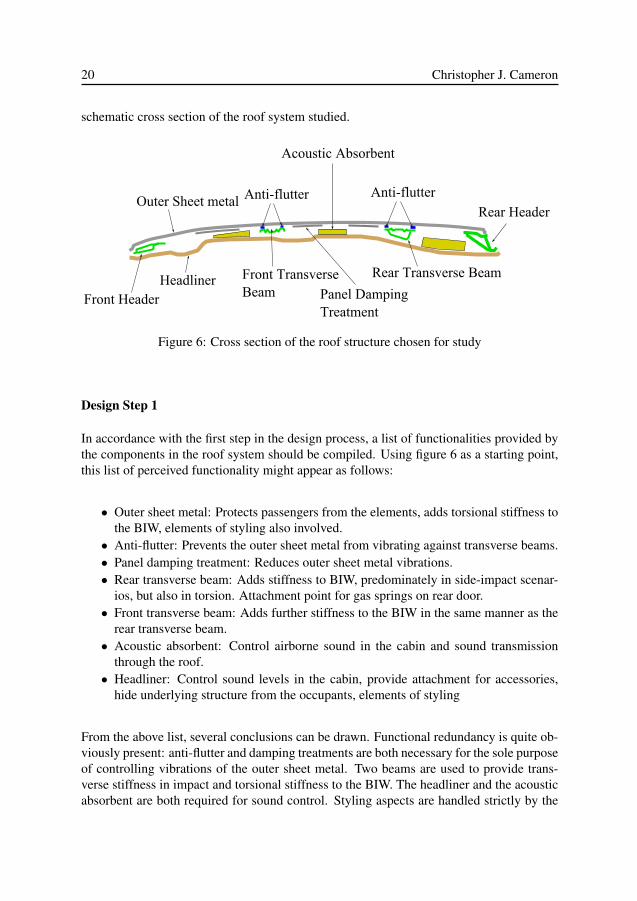
20 Christopher J. Cameron
schematic cross section of the roof system studied.
Outer Sheet metal Anti-flutter Anti-flutter
Acoustic Absorbent
Rear Header
Rear Transverse Beam
Panel DampingTreatment
Front TransverseBeam
HeadlinerFront Header
Figure 6: Cross section of the roof structure chosen for study
Design Step 1
In accordance with the first step in the design process, a list of functionalities provided bythe components in the roof system should be compiled. Using figure 6 as a starting point,this list of perceived functionality might appear as follows:
• Outer sheet metal: Protects passengers from the elements, adds torsional stiffness tothe BIW, elements of styling also involved.
• Anti-flutter: Prevents the outer sheet metal from vibrating against transverse beams.• Panel damping treatment: Reduces outer sheet metal vibrations.• Rear transverse beam: Adds stiffness to BIW, predominately in side-impact scenar-
ios, but also in torsion. Attachment point for gas springs on rear door.• Front transverse beam: Adds further stiffness to the BIW in the same manner as the
rear transverse beam.• Acoustic absorbent: Control airborne sound in the cabin and sound transmission
through the roof.• Headliner: Control sound levels in the cabin, provide attachment for accessories,
hide underlying structure from the occupants, elements of styling
From the above list, several conclusions can be drawn. Functional redundancy is quite ob-viously present: anti-flutter and damping treatments are both necessary for the sole purposeof controlling vibrations of the outer sheet metal. Two beams are used to provide trans-verse stiffness in impact and torsional stiffness to the BIW. The headliner and the acousticabsorbent are both required for sound control. Styling aspects are handled strictly by the
Introduction 21
headliner, which is necessary to hide the unpleasant appearance of the transverse beams,damping material, etc from the passengers.
This description is by no means all encompassing, however it serves as a good startingpoint. As the design philosophy is iterative in nature, any missing aspects can be added ata later stage when a better understanding of the problem has been achieved. Based on thecomponent-wise breakdown of the structure, the following list of actual functional require-ments might be compiled. This is the list which was used to begin the design process.
• Structural stiffness to the BIW both in torsion and side-impact like scenarios• Acoustic absorption• Vibrational damping• Protection from the elements• Styling, including places for lighting, etc
Design step 2
Having established the desired functionality, the next step is to evaluate the system andset performance targets for the new solution. To begin with, a thorough survey of bothSaab’s own internal documentation, and the open literature was performed to establish themethods and tools considered state of the art at the time. The author has attempted topresent this body of knowledge in a concise form in the foregoing chapters, in addition toa more extensive discussion presented in paper III. An initial campaign involving testingand simulation of this state-of-the-art vehicle system was also performed as a supplementto the information in the literature.
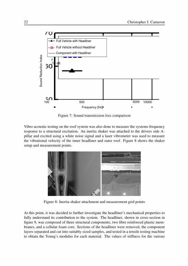
The testing and simulation work involved several steps. Initially, full-vehicle acoustic mea-surement of a production Saab 9-3 Sport Wagon was performed. Following this, the roofstructure of the same production vehicle was removed and sent to KTH where laboratorymeasurement of acoustic and vibro-acoustic properties could be performed. Sound trans-mission loss (STL) testing was performed for both the full vehicle, and for the componentaccording to international standards.
Comparison between the results of STL testing for full vehicle and component can be seenin figure 7. These two results showed very good agreement, and in addition to givingvaluable information on the systems behavior, two additional conclusions of significancecould be drawn which add to the body of scientific knowledge in the field, namely:
• With regards to sound transmission loss testing, for the roof panel at least, and mostcertainly for other body panels, in-situ testing yields sufficiently accurate results asto eliminate the need to disassemble a vehicle to measure individual components.
• In frequencies above approximately 1000 Hz, sound transmission through glass sur-faces contributes significantly to the total sound transmission into the passengercompartment.
22 Christopher J. Cameron
Figure 7: Sound transmission loss comparison
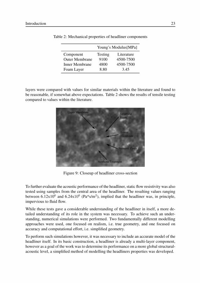
Vibro acoustic testing on the roof system was also done to measure the systems frequencyresponse to a structural excitation. An inertia shaker was attached to the drivers side A-pillar and excited using a white noise signal and a laser vibrometer was used to measurethe vibrational velocity of the inner headliner and outer roof. Figure 8 shows the shakersetup and measurement points.
Figure 8: Inertia shaker attachment and measurement grid points
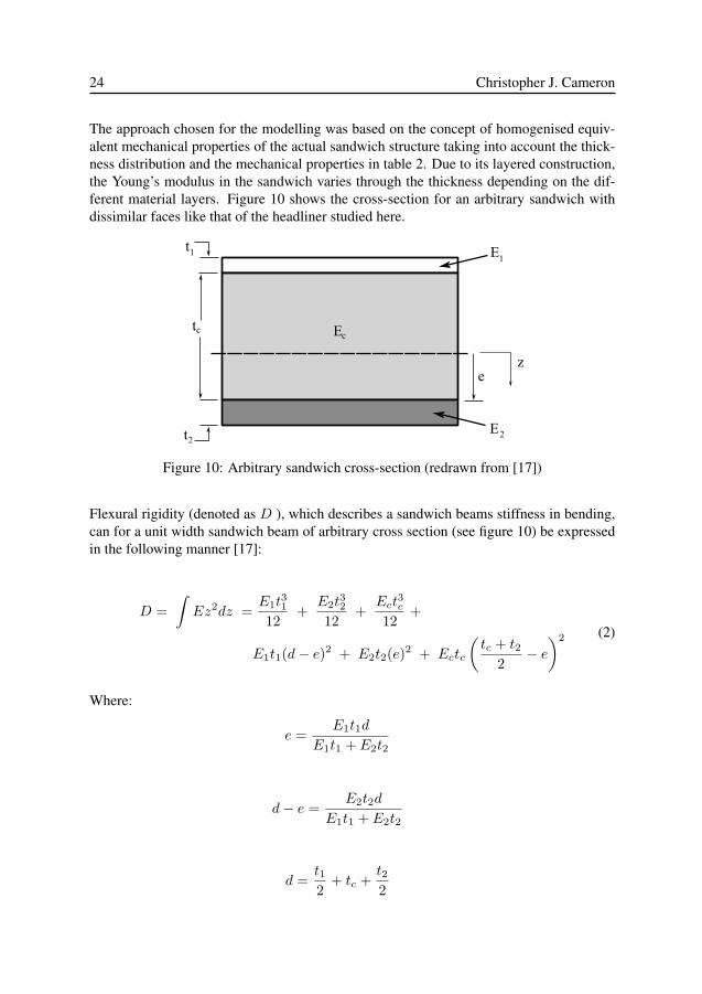
At this point, it was decided to further investigate the headliner’s mechanical properties tofully understand its contribution to the system. The headliner, shown in cross-section infigure 9, was composed of three structural components; two fibre reinforced plastic mem-branes, and a cellular foam core. Sections of the headliner were removed, the componentlayers separated and cut into suitably sized samples, and tested in a tensile testing machineto obtain the Young’s modulus for each material. The values of stiffness for the various
Introduction 23
Table 2: Mechanical properties of headliner components
Young’s Modulus[MPa]
Component Testing LiteratureOuter Membrane 9100 4500-7500Inner Membrane 4800 4500-7500Foam Layer 8.80 3.45
layers were compared with values for similar materials within the literature and found tobe reasonable, if somewhat above expectations. Table 2 shows the results of tensile testingcompared to values within the literature.
Upper Membrane StructuralFoam
Lower Membrane
Acoustic Foam
Aesthetic Treatment
Figure 9: Closeup of headliner cross-section
To further evaluate the acoustic performance of the headliner, static flow resistivity was alsotested using samples from the central area of the headliner. The resulting values rangingbetween 6.12x10⁶ and 6.24x10⁶ (Pa*s/m2), implied that the headliner was, in principle,impervious to fluid flow.
While these tests gave a considerable understanding of the headliner in itself, a more de-tailed understanding of its role in the system was necessary. To achieve such an under-standing, numerical simulations were performed. Two fundamentally different modellingapproaches were used, one focused on realism, i.e. true geometry, and one focused onaccuracy and computational effort, i.e. simplified geometry.
To perform such simulations however, it was necessary to include an accurate model of theheadliner itself. In its basic construction, a headliner is already a multi-layer component,however as a goal of the work was to determine its performance on a more global structural-acoustic level, a simplified method of modelling the headliners properties was developed.
24 Christopher J. Cameron
The approach chosen for the modelling was based on the concept of homogenised equiv-alent mechanical properties of the actual sandwich structure taking into account the thick-ness distribution and the mechanical properties in table 2. Due to its layered construction,the Young’s modulus in the sandwich varies through the thickness depending on the dif-ferent material layers. Figure 10 shows the cross-section for an arbitrary sandwich withdissimilar faces like that of the headliner studied here.
Et
E
Et
t
ez
1
c
2
1
2
c
Figure 10: Arbitrary sandwich cross-section (redrawn from [17])
Flexural rigidity (denoted as D ), which describes a sandwich beams stiffness in bending,can for a unit width sandwich beam of arbitrary cross section (see figure 10) be expressedin the following manner [17]:
D =∫Ez2dz =
E1t31
12+
E2t32
12+
Ect3c
12+
E1t1(d− e)2 + E2t2(e)2 + Ectc
(tc + t2
2− e)2 (2)
Where:
e =E1t1d
E1t1 + E2t2
d− e =E2t2d
E1t1 + E2t2
d =t12
+ tc +t22
Introduction 25
Lower case t denotes a thickness, andE is the Young’s modulus. Subscripts 1 and 2 denotethe upper and lower face sheets. Subscript c denotes the core material. In this case, the facematerials are the two fibre reinforced membranes and the core the structural foam layer.Lower case z denotes the vertical coordinate of the sandwich cross-section where z = 0is the neutral axis of the sandwich structure. By inserting values of t and E into Equation(2), a value can be obtained for the flexural rigidity.
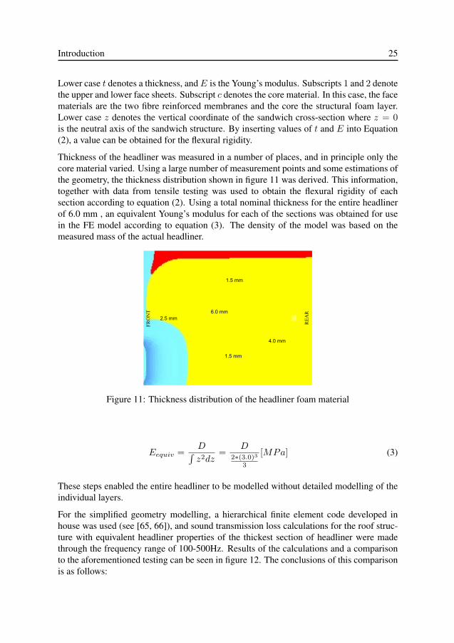
Thickness of the headliner was measured in a number of places, and in principle only thecore material varied. Using a large number of measurement points and some estimations ofthe geometry, the thickness distribution shown in figure 11 was derived. This information,together with data from tensile testing was used to obtain the flexural rigidity of eachsection according to equation (2). Using a total nominal thickness for the entire headlinerof 6.0 mm , an equivalent Young’s modulus for each of the sections was obtained for usein the FE model according to equation (3). The density of the model was based on themeasured mass of the actual headliner.
Figure 11: Thickness distribution of the headliner foam material
Eequiv =D∫z2dz
=D
2∗(3.0)3
3
[MPa] (3)
These steps enabled the entire headliner to be modelled without detailed modelling of theindividual layers.
For the simplified geometry modelling, a hierarchical finite element code developed inhouse was used (see [65, 66]), and sound transmission loss calculations for the roof struc-ture with equivalent headliner properties of the thickest section of headliner were madethrough the frequency range of 100-500Hz. Results of the calculations and a comparisonto the aforementioned testing can be seen in figure 12. The conclusions of this comparisonis as follows:
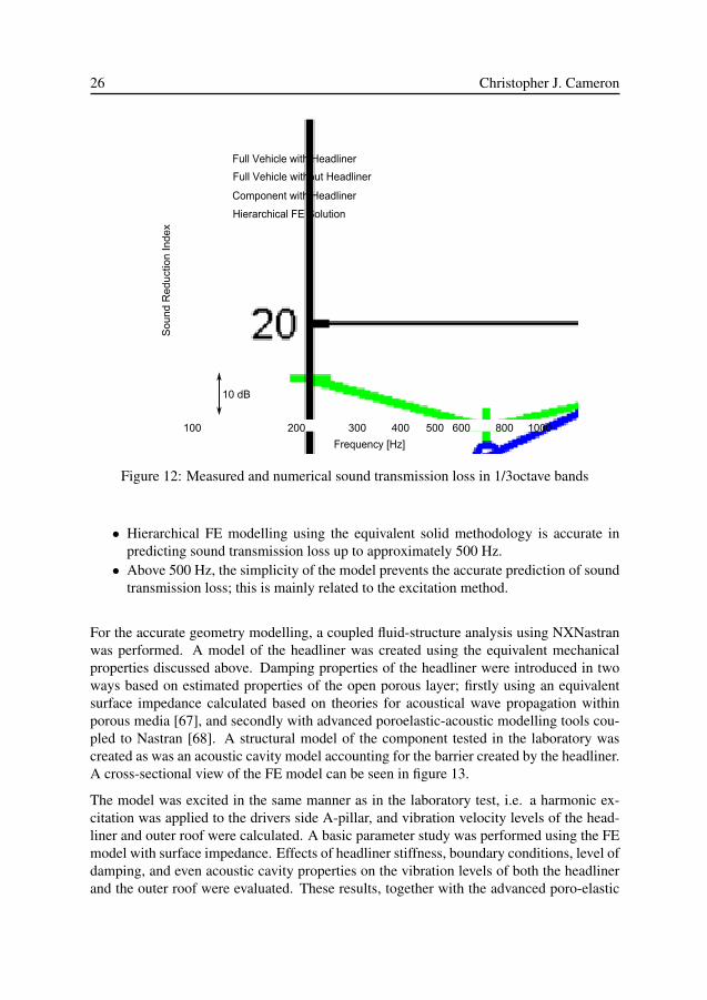
26 Christopher J. Cameron
Figure 12: Measured and numerical sound transmission loss in 1/3octave bands
• Hierarchical FE modelling using the equivalent solid methodology is accurate inpredicting sound transmission loss up to approximately 500 Hz.
• Above 500 Hz, the simplicity of the model prevents the accurate prediction of soundtransmission loss; this is mainly related to the excitation method.
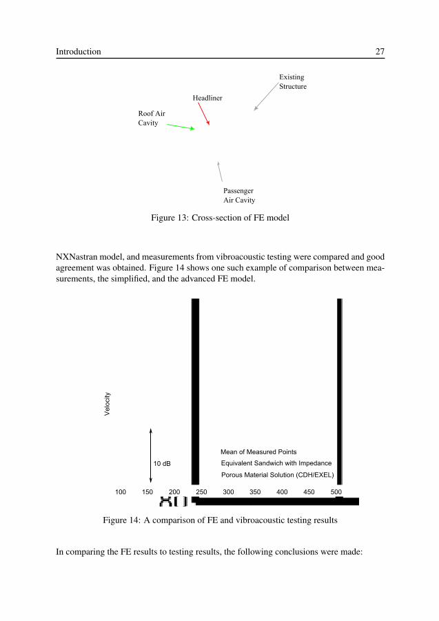
For the accurate geometry modelling, a coupled fluid-structure analysis using NXNastranwas performed. A model of the headliner was created using the equivalent mechanicalproperties discussed above. Damping properties of the headliner were introduced in twoways based on estimated properties of the open porous layer; firstly using an equivalentsurface impedance calculated based on theories for acoustical wave propagation withinporous media [67], and secondly with advanced poroelastic-acoustic modelling tools cou-pled to Nastran [68]. A structural model of the component tested in the laboratory wascreated as was an acoustic cavity model accounting for the barrier created by the headliner.A cross-sectional view of the FE model can be seen in figure 13.
The model was excited in the same manner as in the laboratory test, i.e. a harmonic ex-citation was applied to the drivers side A-pillar, and vibration velocity levels of the head-liner and outer roof were calculated. A basic parameter study was performed using the FEmodel with surface impedance. Effects of headliner stiffness, boundary conditions, level ofdamping, and even acoustic cavity properties on the vibration levels of both the headlinerand the outer roof were evaluated. These results, together with the advanced poro-elastic
Introduction 27
Existing Structure
Headliner
PassengerAir Cavity
Roof AirCavity
Figure 13: Cross-section of FE model
NXNastran model, and measurements from vibroacoustic testing were compared and goodagreement was obtained. Figure 14 shows one such example of comparison between mea-surements, the simplified, and the advanced FE model.
Figure 14: A comparison of FE and vibroacoustic testing results
In comparing the FE results to testing results, the following conclusions were made:
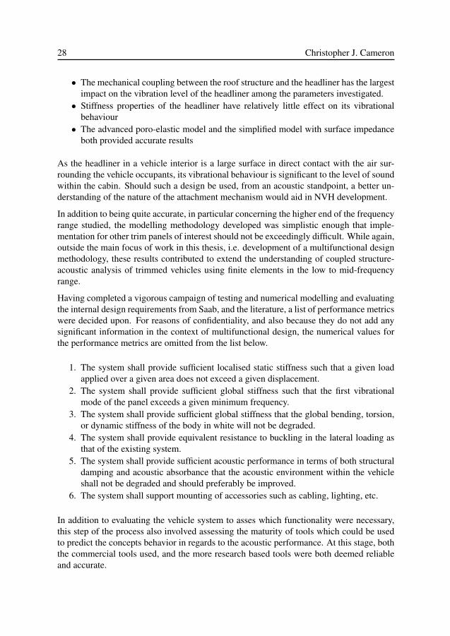
28 Christopher J. Cameron
• The mechanical coupling between the roof structure and the headliner has the largestimpact on the vibration level of the headliner among the parameters investigated.
• Stiffness properties of the headliner have relatively little effect on its vibrationalbehaviour
• The advanced poro-elastic model and the simplified model with surface impedanceboth provided accurate results
As the headliner in a vehicle interior is a large surface in direct contact with the air sur-rounding the vehicle occupants, its vibrational behaviour is significant to the level of soundwithin the cabin. Should such a design be used, from an acoustic standpoint, a better un-derstanding of the nature of the attachment mechanism would aid in NVH development.
In addition to being quite accurate, in particular concerning the higher end of the frequencyrange studied, the modelling methodology developed was simplistic enough that imple-mentation for other trim panels of interest should not be exceedingly difficult. While again,outside the main focus of work in this thesis, i.e. development of a multifunctional designmethodology, these results contributed to extend the understanding of coupled structure-acoustic analysis of trimmed vehicles using finite elements in the low to mid-frequencyrange.
Having completed a vigorous campaign of testing and numerical modelling and evaluatingthe internal design requirements from Saab, and the literature, a list of performance metricswere decided upon. For reasons of confidentiality, and also because they do not add anysignificant information in the context of multifunctional design, the numerical values forthe performance metrics are omitted from the list below.
1. The system shall provide sufficient localised static stiffness such that a given loadapplied over a given area does not exceed a given displacement.
2. The system shall provide sufficient global stiffness such that the first vibrationalmode of the panel exceeds a given minimum frequency.
3. The system shall provide sufficient global stiffness that the global bending, torsion,or dynamic stiffness of the body in white will not be degraded.
4. The system shall provide equivalent resistance to buckling in the lateral loading asthat of the existing system.
5. The system shall provide sufficient acoustic performance in terms of both structuraldamping and acoustic absorbance that the acoustic environment within the vehicleshall not be degraded and should preferably be improved.
6. The system shall support mounting of accessories such as cabling, lighting, etc.
In addition to evaluating the vehicle system to asses which functionality were necessary,this step of the process also involved assessing the maturity of tools which could be usedto predict the concepts behavior in regards to the acoustic performance. At this stage, boththe commercial tools used, and the more research based tools were both deemed reliableand accurate.
Introduction 29
Design step 3
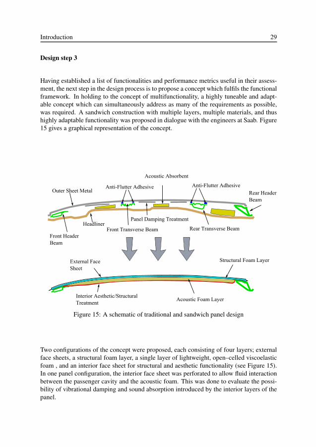
Having established a list of functionalities and performance metrics useful in their assess-ment, the next step in the design process is to propose a concept which fulfils the functionalframework. In holding to the concept of multifunctionality, a highly tuneable and adapt-able concept which can simultaneously address as many of the requirements as possible,was required. A sandwich construction with multiple layers, multiple materials, and thushighly adaptable functionality was proposed in dialogue with the engineers at Saab. Figure15 gives a graphical representation of the concept.
Outer Sheet MetalAnti-Flutter Adhesive
Acoustic Absorbent
Anti-Flutter AdhesiveRear HeaderBeam
Rear Transverse Beam
Panel Damping Treatment
Front Transverse BeamHeadliner
Front Header Beam
External FaceSheet
Acoustic Foam LayerInterior Aesthetic/Structural Treatment
Structural Foam Layer
Figure 15: A schematic of traditional and sandwich panel design
Two configurations of the concept were proposed, each consisting of four layers; externalface sheets, a structural foam layer, a single layer of lightweight, open–celled viscoelasticfoam , and an interior face sheet for structural and aesthetic functionality (see Figure 15).In one panel configuration, the interior face sheet was perforated to allow fluid interactionbetween the passenger cavity and the acoustic foam. This was done to evaluate the possi-bility of vibrational damping and sound absorption introduced by the interior layers of thepanel.
30 Christopher J. Cameron
Table 3: Material properties in FE model for sandwich panels. In cases where propertiesdiffer, perforated values are shown inside square brackets
Outer Sheet Struct. Foam Aco. Foam Inner Sheet
Material Aluminium Closed Cell Foam Open Cell Foam AluminiumE (MPa) 70 000 135 0.10 70 000 [46 460]G (MPa) 26 000 35.0 – 26000 [–]ρ (kg/m3 ) 2710 100 30 2710 [2170]ν 0.3 0.4 0.1 0.3 [0.27]
Design step 4
Using the functional requirements and performance metrics derived in previous steps, anoptimization framework was developed using FEA. Load cases and constraints were con-structed which were deemed sufficient to simulate the required structural and acousticfunctionality demanded in a new design. As this was the first attempt, relatively simplematerials were chosen, isotropic outer face sheets, a standard grade of structural foam, anda typical visco-elastic foam used for acoustic treatments.
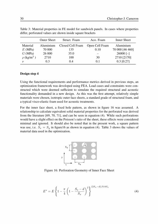
For the inner face sheet, a fixed hole pattern, as shown in figure 16 was assumed. Arelationship to calculate equivalent solid material properties for the perforated was derivedfrom the literature [69, 70, 71], and can be seen in equation (4). While such perforationswould have a slight effect on the Poisson’s ratio of the sheet, these effects were consideredminimal and ignored. It should also be noted that in the present work, a square patternwas use, i.e. Sx = Sy in figure16 as shown in equation (4). Table 3 shows the values ofmaterial data used in the optimization.
d
S
S
y
x x
y
Figure 16: Perforation Geometry of Inner Face Sheet
E∗ = E
{1− π
4
(1− Sx − d
Sx
)2}(2Sx−d)/0.8Sx
(4)
Introduction 31
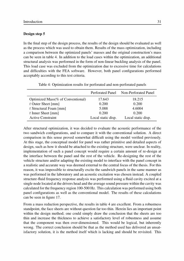
Design step 5
In the final step of the design process, the results of the design should be evaluated as wellas the process which was used to obtain them. Results of the mass optimization, includinga comparison between the optimized panels’ masses and the original construction’s masscan be seen in table 4. In addition to the load cases within the optimization, an additionalstructural analysis was performed in the form of non-linear buckling analysis of the panel.This load case was excluded from the optimization due to excessive time for calculationsand difficulties with the FEA software. However, both panel configurations performedacceptably according to this test criteria.
Table 4: Optimization results for perforated and non-perforated panels
Perforated Panel Non-Perforated Panel
Optimized Mass(% of Conventional) 17.643 18.215t Outer Sheet [mm] 0.200 0.200t Structural Foam [mm] 5.088 4.6004t Inner Sheet [mm] 0.200 0.200Active Constraint Local static disp. Local static disp.
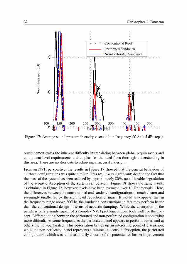
After structural optimization, it was decided to evaluate the acoustic performance of thetwo sandwich configurations, and to compare it with the conventional solution. A directcomparison in this sense proved somewhat difficult using the model verified previously.At this stage, the conceptual model for panel was rather primitive and detailed aspects ofdesign, such as how it should be attached to the existing structure, were unclear. In reality,implementation of such a panel concept would require a certain amount of re-design atthe interface between the panel and the rest of the vehicle. Re-designing the rest of thevehicle structure and/or adapting the existing model to interface with the panel concept ina realistic and accurate way was deemed external to the central focus of the thesis. For thisreason, it was impossible to structurally excite the sandwich panels in the same manner aswas performed in the laboratory and an acoustic excitation was chosen instead. A coupledstructure-fluid frequency response analysis was performed using a fluid cavity excited at asingle node located at the drivers head and the average sound pressure within the cavity wascalculated for the frequency region 100-500 Hz. This calculation was performed using bothpanel configurations as well as the conventional model. The results of these calculationscan be seen in figure 17.
From a mass reduction perspective, the results in table 4 are excellent. From a robustnessstandpoint, the face sheets are without question far too thin. Herein lies an important pointwithin the design method; one could simply draw the conclusion that the sheets are toothin and increase the thickness to achieve a satisfactory level of robustness and assumethat the component was then over-dimensioned. This would be logical, but inherentlywrong. The correct conclusion should be that as the method used has delivered an unsat-isfactory solution, it is the method itself which is lacking and should be revisited. This
32 Christopher J. Cameron
Conventional Roof
Perforated Sandwich
Non-Perforated Sandwich
Frequency [Hz]
Sou
nd P
ress
ure
[dB
]
100 150 200 250 300 350 400 450 500
Figure 17: Average sound pressure in cavity vs excitation frequency (Y-Axis 5 dB steps)
result demonstrates the inherent difficulty in translating between global requirements andcomponent level requirements and emphasises the need for a thorough understanding inthis area. There are no shortcuts to achieving a successful design.
From an NVH perspective, the results in Figure 17 showed that the general behaviour ofall three configurations was quite similar. This result was significant; despite the fact thatthe mass of the system has been reduced by approximately 80%, no noticeable degradationof the acoustic absorption of the system can be seen. Figure 18 shows the same resultsas obtained in Figure 17, however levels have been averaged over 10 Hz intervals. Here,the differences between the conventional and sandwich configurations is much clearer andseemingly unaffected by the significant reduction of mass. It would also appear, that inthe frequency range above 300Hz, the sandwich constructions in fact may perform betterthan the conventional design in terms of acoustic damping. While the absorption of thepanels is only a single aspect of a complex NVH problem, it does bode well for the con-cept. Differentiating between the perforated and non-perforated configuration is somewhatmore difficult. At some frequencies the perforated panel appears to perform better, and atothers the non-perforated. This observation brings up an interesting point of discussion;while the non-perforated panel represents a minima in acoustic absorption, the perforatedconfiguration, which was rather arbitrarily chosen, offers potential for further improvement
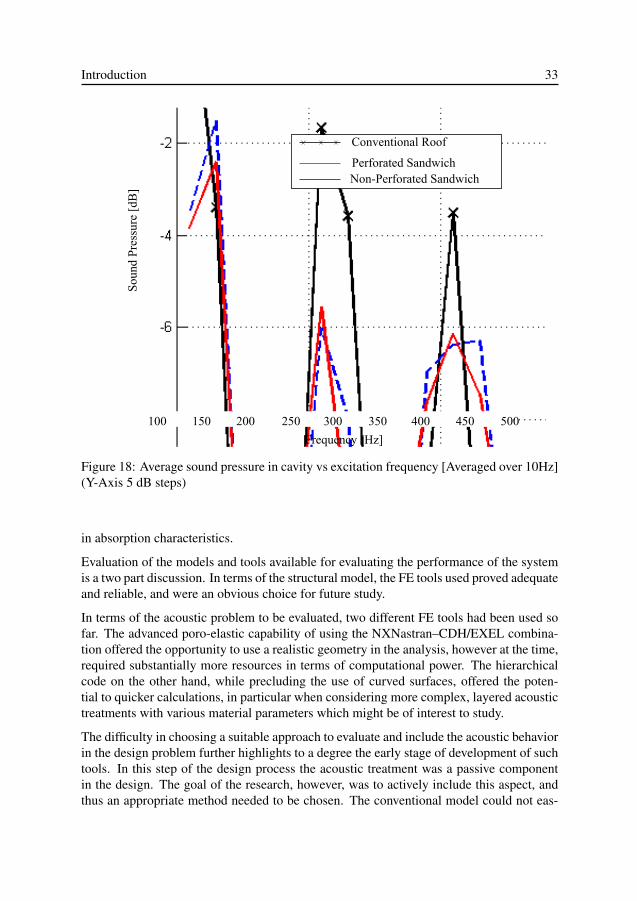
Introduction 33
Conventional Roof
Perforated SandwichNon-Perforated Sandwich
Frequency [Hz]
Sou
nd P
ress
ure
[dB
]
100 150 200 250 300 350 400 450 500
Figure 18: Average sound pressure in cavity vs excitation frequency [Averaged over 10Hz](Y-Axis 5 dB steps)
in absorption characteristics.
Evaluation of the models and tools available for evaluating the performance of the systemis a two part discussion. In terms of the structural model, the FE tools used proved adequateand reliable, and were an obvious choice for future study.
In terms of the acoustic problem to be evaluated, two different FE tools had been used sofar. The advanced poro-elastic capability of using the NXNastran–CDH/EXEL combina-tion offered the opportunity to use a realistic geometry in the analysis, however at the time,required substantially more resources in terms of computational power. The hierarchicalcode on the other hand, while precluding the use of curved surfaces, offered the poten-tial to quicker calculations, in particular when considering more complex, layered acoustictreatments with various material parameters which might be of interest to study.
The difficulty in choosing a suitable approach to evaluate and include the acoustic behaviorin the design problem further highlights to a degree the early stage of development of suchtools. In this step of the design process the acoustic treatment was a passive componentin the design. The goal of the research, however, was to actively include this aspect, andthus an appropriate method needed to be chosen. The conventional model could not eas-
34 Christopher J. Cameron
ily be compared with the sandwich concepts more than already shown due the problemof achieving equivalent structural excitation. In addition, calculations with this softwaretook considerably longer and were more complicated in setting up and executing. As men-tioned, the hierarchical code offered considerably more flexibility in terms of studying theacoustic treatment. For these reasons, it was decided that future iterations of design pro-cess should use the in-house hierarchical code and a more relevant structural excitation.As the accuracy of the code had already been validated, the change in load case used wasnot considered a difficulty.
Having addressed the question of whether the tools and methods used were sufficient,which led to some obvious need to revisit the method of refinement, it was also interestingto investigate if the functional requirements have been achieved. In terms of the acousticperformance from the standpoint of acoustic absorption, good performance was obtained.For the case of the structural functionality the structural requirements established werefulfilled at a drastically reduced weight. As the final solution is however unsatisfactory, areturn to the first step in the process, and a re-evaluation for the functional requirements ofthe system is necessary.
Iteration 2
As the step by step process has now been discussed in detail, and much of it remainsstatic through the design process, the author feels it unnecessary repetition to review thesubsequent iterations on a step by step basis. Instead, a more general review of the changesmade will be given and the reader is encouraged to make the connections to the correctstep in the design method on their own.
A second interaction initiated using the lessons learnt in the first iteration should have ahigher chance of success. In working with such an iterative design approach, it should beremembered that failure to achieve a successful design immediately is not in fact a failure.Each unsuccessful attempt to achieve functionality and fulfil design constraints should beseen as a step towards a more complete understanding of the problem. Especially whendealing with a multidisciplinary design task, it is highly unlikely that all aspects of theproblem or consequences of solutions proposed to address them, will or can be understoodfrom the outset.
In the second iteration, the significance of the resulting face sheets from the first iterationwere examined further. Clearly, these were too thin to be robust for daily use, but also,it could be interpreted that since so little material was necessary to achieve the structuralrequirements, a material of lower mechanical stiffness and lower density might be appro-priate. The list of functional requirements was augmented as follows:
• The exterior surfaces shall have adequate robustness so as to be unaffected by every-day use
Introduction 35
• The system shall provide sufficient stiffness where required and avoid excessive stiff-ness where unnecessary
The addition of the first of these two requirements, which may be considered obvious andtrivial, is an excellent example of how essential characteristics can be overlooked becausethey are so fundamental as to be taken for granted. In this sense, an iterative approach ishelpful.
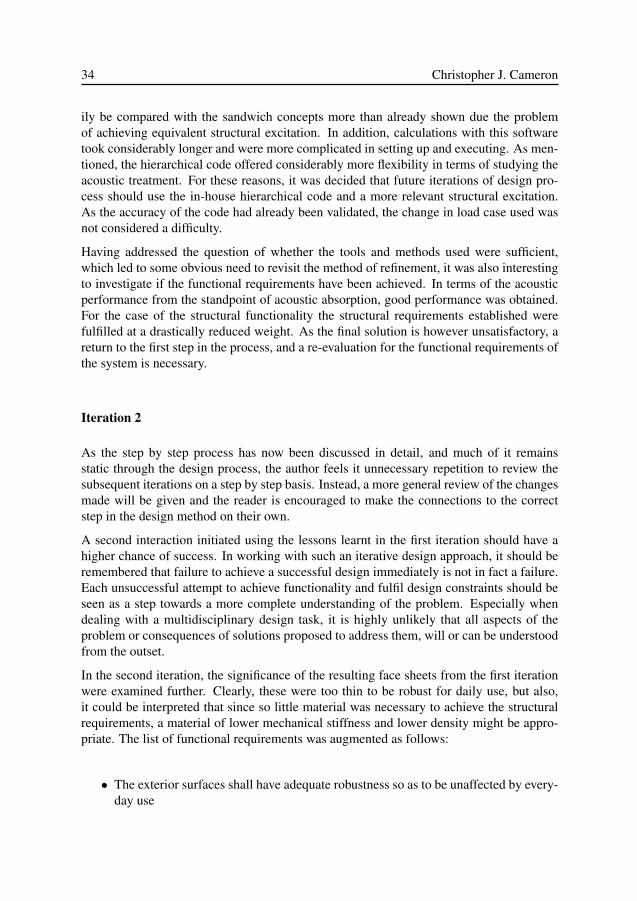
Glass fibre composite was proposed for both the exterior and interior face sheets as it wasboth lower density and lower stiffness than aluminium, as used in the previous iteration.A directional laminate was proposed for the exterior face sheet, and a chopped strand mat(CSM) for the interior face sheet. A framework of structural foam was added around theedges of the panel, and a single narrow band transversely through the centre of the panel,to further increase global stiffness. As the previous solution with a perforated face sheetoffered potential for improvement, such a solution was chosen for further study and thenon-perforated concept was abandoned. Further focus was also placed on the acoustictreatment, and the single layer of visco-elastic foam was split into three separate layers.Figure 19 shows a cross-section of the proposed layup.
Figure 19: A cross-sectional view of the layup used for iteration 2
To explore the limits of mass reduction in the structure, the material properties of boththe outer face sheet and the structural foam were introduced as design variables in theoptimization scheme. Fiber volume fraction in each layer of the outer face sheet was usedas a design variable to control the mechanical properties of the layer according to equations(5 - 9). This approach was chosen to allow the optimization algorithm to replace the higherdensity glass fibre with lower density matrix material where the structure would allow.
E11 = (Vf )Ef11 + (1.0− Vf )Em (5)
36 Christopher J. Cameron
E12 = E13 =Vf
Ef+
1− Vf
Em(6)
G12 = G13 =Gm
1−√Vf (1−Gm/Gf12)
(7)
G23 =Gm
1− Vf (1−Gm/Gf12)(8)
νlamina = Vf · νf + (1− Vf ) · νm (9)
Structural foam density was used to control its mechanical properties according to relationsestablished in the literature [72]. A closed cell foam was assumed using the bulk propertiesof PET. The relationship between the structural foam’s density and its mechanical prop-erties can be seen in equations (10 - 12). Material properties of the inner face sheet werecontrolled with the degree of perforation, as shown previously in figure 16 and equation(4).
Efoam
Esolid≈ φ2
(ρfoam
ρsolid
)2
+ (1− φ)ρfoam
ρsolid
+P0(1− 2νfoam)
Esolid − ρfoam/ρsolid(10)
Gfoam
Esolid≈ 3
8
(φ2(
ρfoam
ρsolid)2 + (1− φ)
ρfoam
ρsolid
)(11)
νfoam ≈13
(12)
Slight changes were also made to the structural analysis scheme. The method of loadingfor the localised load was slightly adjusted, and an additional static load case in the formof distributed pressure over the entire panel was also added to increase the robustness ofthe solution.
To explore the potential of the acoustic treatment, acoustic calculations were added to theoptimization scheme to introduce an active acoustic design aspect rather than a reactiveevaluation tool. This was done using the hierarchical FE code with a simplified geometrymodel of the panel. By introducing the acoustic model with a separate finite element solver,the optimization scheme effectively became a two step process. Structural calculationswere best addressed using the conventional FE solver, and acoustic characteristics couldonly be addressed using the hierarchical FE code.
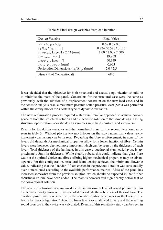
Introduction 37
Table 5: Final design variables from 2nd iteration
Design Variable Final Value
Vf0 / Vf45 / Vf90 0.6 / 0.6 / 0.6t0 /t45 / t90 [mm] 0.224 / 0.521 / 0.125tACFoam Layer 1 / 2 / 3 [mm] 1.00 / 1.00 / 7.500tSTFoam [mm] 19.868ρSTFoam [kg/m3] 50.149tInnerFaceSheet [mm] 0.693Perforation Dimensions ( d/Sx,y )[mm] 2.0 / 2.5
Mass (% of Conventional) 68.6
It was decided that the objective for both structural and acoustic optimization should beto minimise the mass of the panel. Constraints for the structural case were the same aspreviously, with the addition of a displacement constraint on the new load case, and inthe acoustic analysis case, a maximum possible sound pressure level (SPL) was permittedwithin the cavity model for a certain type of dynamic excitation.
The new optimization process required a stepwise iterative approach to achieve conver-gence of both the structural solution and the acoustic solution to the same design. Duringstructural optimization, acoustic design variables were held constant, and vice-versa.
Results for the design variables and the normalised mass for the second iteration can beseen in table 5. Without placing too much focus on the exact numerical values, someimportant conclusions can be drawn. Regarding the fibre reinforcement, in none of thelayers did demands for mechanical properties allow for a lower fraction of fibre. Certainlayers were however deemed more important which can be seen by the thickness of eachlayer. Total thickness of the laminate, in this case a quadraxial symmetric layup, is ap-proximately 3mm in thickness. While clearly robust, this could indicate that glass fibrewas not the optimal choice and fibres offering higher mechanical properties may be advan-tageous. For this configuration, structural foam density achieved the minimum allowablevalue, indicating that the "standard" foam chosen in the previous iteration was substantiallyover-dimensioned according to the available performance metrics. Mass of the panel hasincreased somewhat from the previous solution, which should be expected in that furtherrobustness criteria have been added. The mass is however still significantly below that ofthe conventional solution.
The acoustic optimization maintained a constant maximum level of sound pressure withinthe acoustic cavity, however it was decided to evaluate the robustness of this solution. Thequestion posed was how sensitive is the acoustic solution to changes in thickness of thelayers for this configuration? Acoustic foam layers were allowed to vary and the resultingsound pressure in the cavity was calculated. Results of this sensitivity study can be seen in

38 Christopher J. Cameron
figures 20 and 21.
Figure 20: Weight penalty for increasing acoustic layer thickness
What can be seen in these two figures is the obvious fact that for a maximum and minimumthickness of acoustic foam, the maximum and minimum weight penalty and minimum andmaximum SPL in the cavity are achieved. What is more intriguing is the results of figure21, which show that for a configuration with a relatively thick layer 1 and relatively thinlayer 3, the SPL is nearly as good as that of the maximum thickness acoustic treatment.
Having completed the final step in the design phase once again, it was necessary to re-evaluate the results, and the methods used. This time, the output of the design processfulfilled all the necessary functional requirements and had a lower mass than the benchmarksystem. Adding the active acoustic design portions to the problem increased the complexityof the analysis, but added significant worth to the results. In examining the results ofthe acoustic sensitivity study, it was decided that further examination was necessary. Ifvariations of thickness of two foams chosen based only on a best estimate of applicability,what could a more systematic approach to choosing an acoustic treatment yield in terms ofperformance, and what effect might it have on the structure?
Iteration 3
In the third iteration, it was decided to further investigate the potential for weight savings inthe structure by using a higher performance and lower mass composite system, i.e. carbonfibres instead of glass. In terms of the acoustic system, it was decided to investigate the ef-fects of stacking sequence and material choice on the panels performance. Variables whichdescribe the elastic, acoustic, and dissipative properties of the acoustic foam layers wereintroduced into the optimisation framework. For a detailed description of these variables
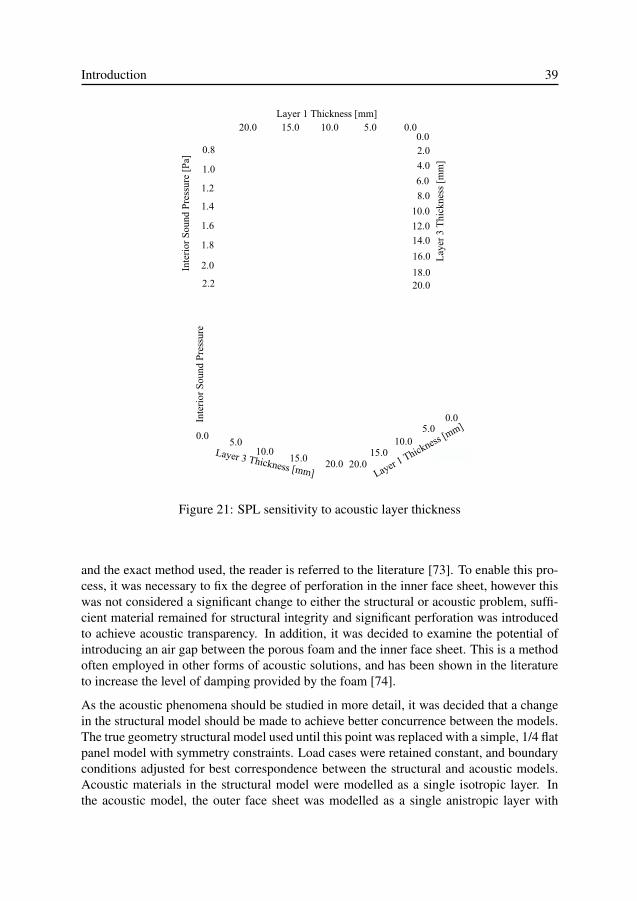
Introduction 39
Figure 21: SPL sensitivity to acoustic layer thickness
and the exact method used, the reader is referred to the literature [73]. To enable this pro-cess, it was necessary to fix the degree of perforation in the inner face sheet, however thiswas not considered a significant change to either the structural or acoustic problem, suffi-cient material remained for structural integrity and significant perforation was introducedto achieve acoustic transparency. In addition, it was decided to examine the potential ofintroducing an air gap between the porous foam and the inner face sheet. This is a methodoften employed in other forms of acoustic solutions, and has been shown in the literatureto increase the level of damping provided by the foam [74].
As the acoustic phenomena should be studied in more detail, it was decided that a changein the structural model should be made to achieve better concurrence between the models.The true geometry structural model used until this point was replaced with a simple, 1/4 flatpanel model with symmetry constraints. Load cases were retained constant, and boundaryconditions adjusted for best correspondence between the structural and acoustic models.Acoustic materials in the structural model were modelled as a single isotropic layer. Inthe acoustic model, the outer face sheet was modelled as a single anistropic layer with
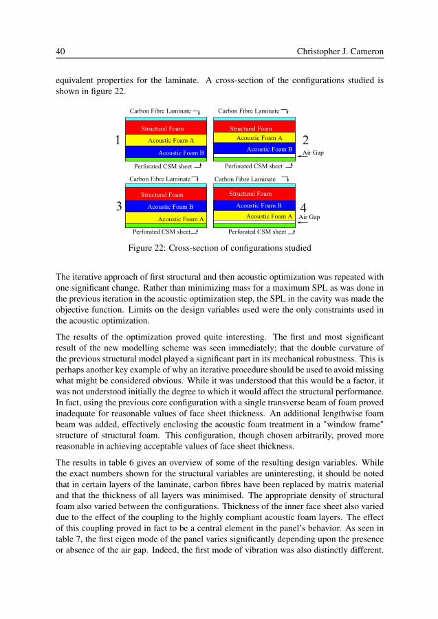
40 Christopher J. Cameron
equivalent properties for the laminate. A cross-section of the configurations studied isshown in figure 22.
Figure 22: Cross-section of configurations studied
The iterative approach of first structural and then acoustic optimization was repeated withone significant change. Rather than minimizing mass for a maximum SPL as was done inthe previous iteration in the acoustic optimization step, the SPL in the cavity was made theobjective function. Limits on the design variables used were the only constraints used inthe acoustic optimization.
The results of the optimization proved quite interesting. The first and most significantresult of the new modelling scheme was seen immediately; that the double curvature ofthe previous structural model played a significant part in its mechanical robustness. This isperhaps another key example of why an iterative procedure should be used to avoid missingwhat might be considered obvious. While it was understood that this would be a factor, itwas not understood initially the degree to which it would affect the structural performance.In fact, using the previous core configuration with a single transverse beam of foam provedinadequate for reasonable values of face sheet thickness. An additional lengthwise foambeam was added, effectively enclosing the acoustic foam treatment in a "window frame"structure of structural foam. This configuration, though chosen arbitrarily, proved morereasonable in achieving acceptable values of face sheet thickness.
The results in table 6 gives an overview of some of the resulting design variables. Whilethe exact numbers shown for the structural variables are uninteresting, it should be notedthat in certain layers of the laminate, carbon fibres have been replaced by matrix materialand that the thickness of all layers was minimised. The appropriate density of structuralfoam also varied between the configurations. Thickness of the inner face sheet also varieddue to the effect of the coupling to the highly compliant acoustic foam layers. The effectof this coupling proved in fact to be a central element in the panel’s behavior. As seen intable 7, the first eigen mode of the panel varies significantly depending upon the presenceor absence of the air gap. Indeed, the first mode of vibration was also distinctly different.
Introduction 41
Table 6: Final values for design variables in the 3rd iteration
ConfigurationVariable 1 2 3 4Vf0,90 0.60 0.60 0.60 0.60Vf45 0.27 0.26 0.29 0.29t0,45,90[mm] 0.15 0.15 0.15 0.15tPETfoam[mm] 25.0 25.0 25.0 25.0ρPETfoam[kg/m3] 134.2 128.2 142.5 140.5tCSM [mm] 2.91 3.50 2.86 3.50ρ∗PU [kg/m3] 38.62 137.97 137.74 137.97σstatic
PU [kg/m3/s] 5.45e3 1.11e5 1.10e5 1.11e5tPU 23.04 48.00 47.19 41.49ρ∗pi [kg/m3] 9.31 1.48 2.46 3.86σstatic
pi [kg/m3/s] 1.39e6 2.94e4 8.29e4 2.12e5tpi [mm] 26.96 1.000 2.4617 4.585
Table 7: Results of optimization
ConfigurationValue 1 2 3 4Total Thickness [mm] 79.1 78.7 78.7 75.8Total Mass [kg] 18.7 27.3 27.8 26.7SPL [dB] 60.1 59.3 57.9 58.5First Eigen Mode [Hz] 71.8 46.9 64.7 47.0
For configurations with an air gap, the inner face sheet began to vibrate and its thicknesswas dictated by this fundamental vibration mode. For the bonded configuration, the panelbehaved more as a unified structure and the mode of vibration was a global mode for theentire panel.
The variation in acoustic variables, and the resulting mass and SPL are also rather striking.By simply changing the stacking sequence of the foams, large differences in mass, andsignificant differences in sound pressure were obtained. While the highest and lowest SPLwas obtained for the lightest and heaviest panels respectively, the difference in SPL cannotbe accounted for in terms of mass alone. In this sense, while differences in geometryprevent a direct comparison to the original solution, the lightweight panel would be mostattractive despite its noticeably poorer acoustic performance. Properties of the foams provehere to be a crucial attribute in the panels acoustic functionality. This again highlights thedangers of using an arbitrarily chosen acoustic treatment and the need for a more systematicapproach.
42 Christopher J. Cameron
In assessing the overall results from this iteration, it can be said that the general methods ofusing material properties and thicknesses for both the acoustic and structural optimizationappear rather promising. The fundamental problem with the solution however is the arbi-trarily chosen "window frame" configuration of the structural foam core. The chances ofsuch a design being the optimal lightweight solution are very low. In fact, it is most likelya contributing factor to the large difference in mass, and the significantly higher struc-tural foam density in comparison to the previous iteration. One might experiment withsuch a configuration, varying the width, number, and placement of such beams, howeverthis would be a very unstructured approach and require a certain degree of luck. Such anad-hoc process might be considered the anti-thesis of the present paradigm of multifunc-tional design. A more structured, logical approach for developing the structural frameworkshould thus be implemented.
Iteration 4
In the fourth and final iteration of the design loop discussed within this thesis, the topol-ogy of the structural foam core was examined in detail. In previous iterations, an ratherarbitrarily chosen "window frame" design was used. The limitations of such a design be-came expressly apparent, firstly when switching to a flat panel model from a double curvedsurface, and secondly when the air gap was added to the acoustic treatment. While the win-dow frame concept was functional, it was most certainly not optimized regarding any ofthe relevant performance metrics discussed.
In addition, results from the previous iteration indicated that the air gap configuration ex-amined added negative attributes to the structural performance, but did appear to offer aslight improvement in terms of acoustic functionality. One difficulty in assessing the airgaps affect was its strong influence on the structures overall behavior. The author wouldassert in fact, that the introduction of such an air gap fundamentally changes the structuresbehavior, to a lesser degree in static load cases, but to a largely significant degree in itsdynamic response. This makes the comparison between an air gap and non air gap config-uration of the window frame design difficult if not impossible from a combined structuraland acoustic functionality standpoint.
Topology optimization was the approach chosen to deal with these problems. As men-tioned in the previous chapters, the BESO method was chosen as a starting point for thistask. The BESO method is well documented [59, 75, 76, 60, 77, 78, 79] and as a detaileddiscussion of its principles would not add worth to the present discussion, the interestedreader is directed to the literature. For the sake of understanding however, a few simpleprinciples will be reviewed.
In short, the BESO method strives to create an effectively stressed structure by addingor subtracting element within a finite element model based on their so called sensitivitynumber. Sensitivity numbers differ according to the type of load case assessed, and forthe case of multiple load cases, a method of normalising sensitivity numbers between load
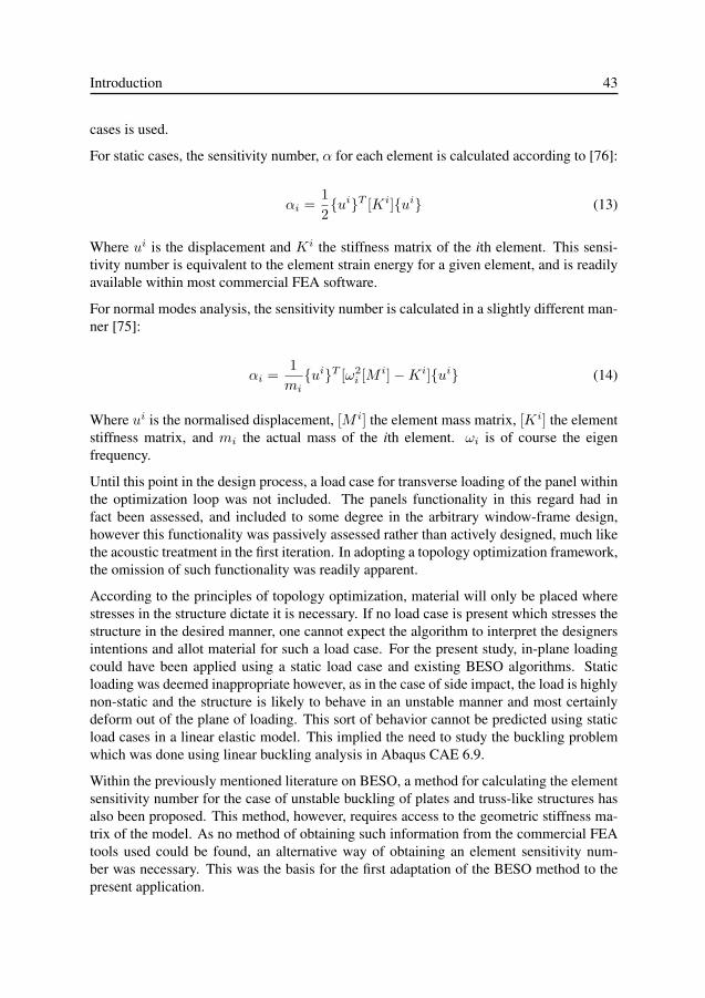
Introduction 43
cases is used.
For static cases, the sensitivity number, α for each element is calculated according to [76]:
αi =12{ui}T [Ki]{ui} (13)
Where ui is the displacement and Ki the stiffness matrix of the ith element. This sensi-tivity number is equivalent to the element strain energy for a given element, and is readilyavailable within most commercial FEA software.
For normal modes analysis, the sensitivity number is calculated in a slightly different man-ner [75]:
αi =1mi{ui}T [ω2
i [M i]−Ki]{ui} (14)
Where ui is the normalised displacement, [M i] the element mass matrix, [Ki] the elementstiffness matrix, and mi the actual mass of the ith element. ωi is of course the eigenfrequency.
Until this point in the design process, a load case for transverse loading of the panel withinthe optimization loop was not included. The panels functionality in this regard had infact been assessed, and included to some degree in the arbitrary window-frame design,however this functionality was passively assessed rather than actively designed, much likethe acoustic treatment in the first iteration. In adopting a topology optimization framework,the omission of such functionality was readily apparent.
According to the principles of topology optimization, material will only be placed wherestresses in the structure dictate it is necessary. If no load case is present which stresses thestructure in the desired manner, one cannot expect the algorithm to interpret the designersintentions and allot material for such a load case. For the present study, in-plane loadingcould have been applied using a static load case and existing BESO algorithms. Staticloading was deemed inappropriate however, as in the case of side impact, the load is highlynon-static and the structure is likely to behave in an unstable manner and most certainlydeform out of the plane of loading. This sort of behavior cannot be predicted using staticload cases in a linear elastic model. This implied the need to study the buckling problemwhich was done using linear buckling analysis in Abaqus CAE 6.9.
Within the previously mentioned literature on BESO, a method for calculating the elementsensitivity number for the case of unstable buckling of plates and truss-like structures hasalso been proposed. This method, however, requires access to the geometric stiffness ma-trix of the model. As no method of obtaining such information from the commercial FEAtools used could be found, an alternative way of obtaining an element sensitivity num-ber was necessary. This was the basis for the first adaptation of the BESO method to thepresent application.
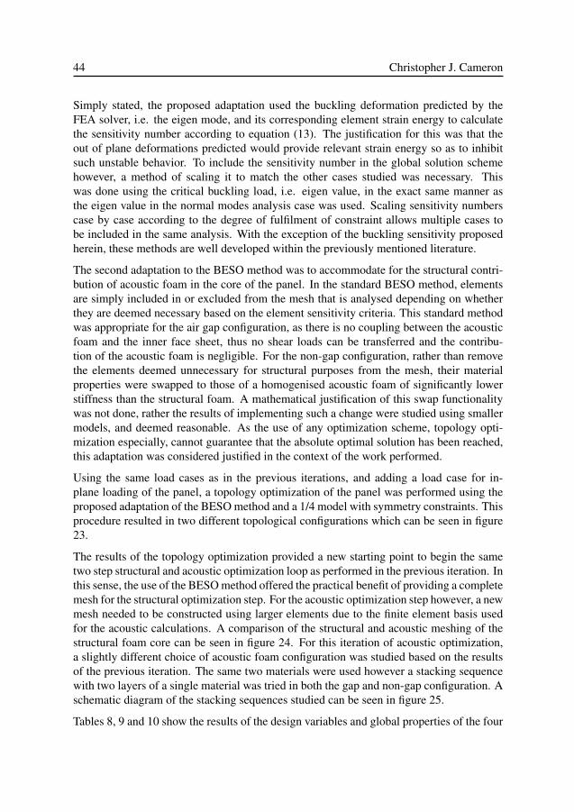
44 Christopher J. Cameron
Simply stated, the proposed adaptation used the buckling deformation predicted by theFEA solver, i.e. the eigen mode, and its corresponding element strain energy to calculatethe sensitivity number according to equation (13). The justification for this was that theout of plane deformations predicted would provide relevant strain energy so as to inhibitsuch unstable behavior. To include the sensitivity number in the global solution schemehowever, a method of scaling it to match the other cases studied was necessary. Thiswas done using the critical buckling load, i.e. eigen value, in the exact same manner asthe eigen value in the normal modes analysis case was used. Scaling sensitivity numberscase by case according to the degree of fulfilment of constraint allows multiple cases tobe included in the same analysis. With the exception of the buckling sensitivity proposedherein, these methods are well developed within the previously mentioned literature.
The second adaptation to the BESO method was to accommodate for the structural contri-bution of acoustic foam in the core of the panel. In the standard BESO method, elementsare simply included in or excluded from the mesh that is analysed depending on whetherthey are deemed necessary based on the element sensitivity criteria. This standard methodwas appropriate for the air gap configuration, as there is no coupling between the acousticfoam and the inner face sheet, thus no shear loads can be transferred and the contribu-tion of the acoustic foam is negligible. For the non-gap configuration, rather than removethe elements deemed unnecessary for structural purposes from the mesh, their materialproperties were swapped to those of a homogenised acoustic foam of significantly lowerstiffness than the structural foam. A mathematical justification of this swap functionalitywas not done, rather the results of implementing such a change were studied using smallermodels, and deemed reasonable. As the use of any optimization scheme, topology opti-mization especially, cannot guarantee that the absolute optimal solution has been reached,this adaptation was considered justified in the context of the work performed.
Using the same load cases as in the previous iterations, and adding a load case for in-plane loading of the panel, a topology optimization of the panel was performed using theproposed adaptation of the BESO method and a 1/4 model with symmetry constraints. Thisprocedure resulted in two different topological configurations which can be seen in figure23.
The results of the topology optimization provided a new starting point to begin the sametwo step structural and acoustic optimization loop as performed in the previous iteration. Inthis sense, the use of the BESO method offered the practical benefit of providing a completemesh for the structural optimization step. For the acoustic optimization step however, a newmesh needed to be constructed using larger elements due to the finite element basis usedfor the acoustic calculations. A comparison of the structural and acoustic meshing of thestructural foam core can be seen in figure 24. For this iteration of acoustic optimization,a slightly different choice of acoustic foam configuration was studied based on the resultsof the previous iteration. The same two materials were used however a stacking sequencewith two layers of a single material was tried in both the gap and non-gap configuration. Aschematic diagram of the stacking sequences studied can be seen in figure 25.
Tables 8, 9 and 10 show the results of the design variables and global properties of the four
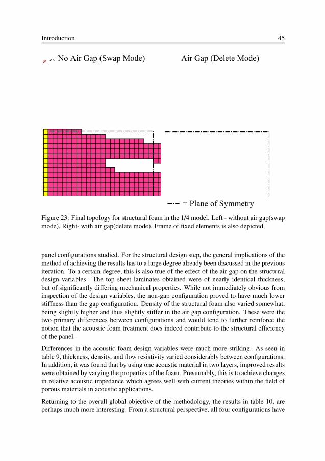
Introduction 45
Figure 23: Final topology for structural foam in the 1/4 model. Left - without air gap(swapmode), Right- with air gap(delete mode). Frame of fixed elements is also depicted.
panel configurations studied. For the structural design step, the general implications of themethod of achieving the results has to a large degree already been discussed in the previousiteration. To a certain degree, this is also true of the effect of the air gap on the structuraldesign variables. The top sheet laminates obtained were of nearly identical thickness,but of significantly differing mechanical properties. While not immediately obvious frominspection of the design variables, the non-gap configuration proved to have much lowerstiffness than the gap configuration. Density of the structural foam also varied somewhat,being slightly higher and thus slightly stiffer in the air gap configuration. These were thetwo primary differences between configurations and would tend to further reinforce thenotion that the acoustic foam treatment does indeed contribute to the structural efficiencyof the panel.
Differences in the acoustic foam design variables were much more striking. As seen intable 9, thickness, density, and flow resistivity varied considerably between configurations.In addition, it was found that by using one acoustic material in two layers, improved resultswere obtained by varying the properties of the foam. Presumably, this is to achieve changesin relative acoustic impedance which agrees well with current theories within the field ofporous materials in acoustic applications.
Returning to the overall global objective of the methodology, the results in table 10, areperhaps much more interesting. From a structural perspective, all four configurations have
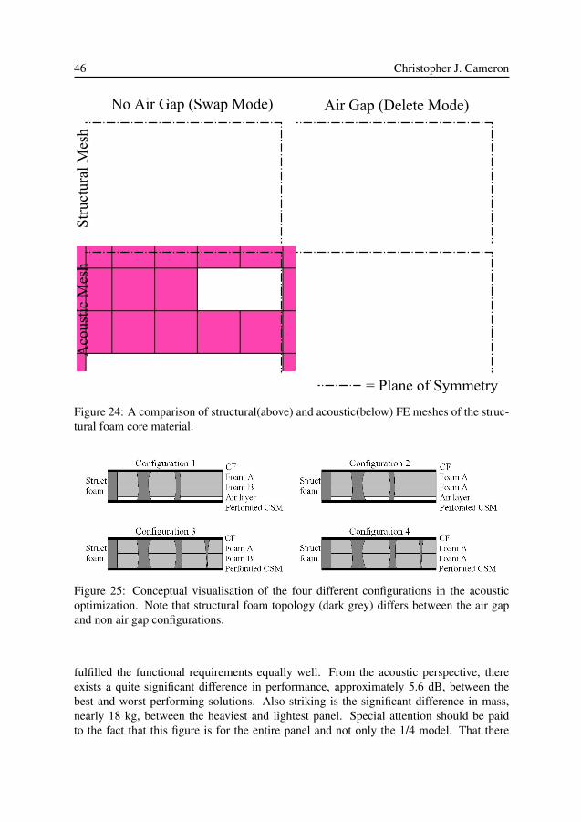
46 Christopher J. Cameron
Figure 24: A comparison of structural(above) and acoustic(below) FE meshes of the struc-tural foam core material.
Figure 25: Conceptual visualisation of the four different configurations in the acousticoptimization. Note that structural foam topology (dark grey) differs between the air gapand non air gap configurations.
fulfilled the functional requirements equally well. From the acoustic perspective, thereexists a quite significant difference in performance, approximately 5.6 dB, between thebest and worst performing solutions. Also striking is the significant difference in mass,nearly 18 kg, between the heaviest and lightest panel. Special attention should be paidto the fact that this figure is for the entire panel and not only the 1/4 model. That there
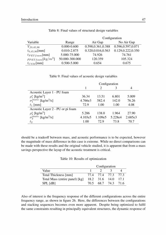
Introduction 47
Table 8: Final values of structural design variables
ConfigurationVariable Range Air Gap No Air GapVf0,45,90 0.000-0.600 0.598,0.361,0.388 0.596,0.597,0.071t0,45,90[mm] 0.010-2.875 0.320,0.016,0.563 0.129,0.222,0.350tPETfoam[mm] 5.000-75.000 74.926 74.761ρPETfoam[kg/m3] 50.000-300.000 120.359 105.324tCSM [mm] 0.500-5.000 0.654 0.675
Table 9: Final values of acoustic design variables
Configuration1 2 3 4
Acoustic Layer 1 - PU foamρ∗1 [kg/m3] 36.34 13.51 6.801 5.009σstatic
1 [kg/m3/s] 4.766e3 582.4 142.0 76.26t1 [mm] 72.9 1.00 1.00 4.08Acoustic Layer 2 - PU or pi foamρ∗2 [kg/m3] 5.286 138.0 1.964 27.90σstatic
2 [kg/m3/s] 4.103e5 1.109e5 5.228e4 2.685e3t2 1.00 72.9 73.8 70.7
should be a tradeoff between mass, and acoustic performance is to be expected, howeverthe magnitude of mass difference in this case is extreme. While no direct comparisons canbe made with these results and the original vehicle studied, it is apparent that from a masssavings perspective the layup of the acoustic treatment is critical.
Table 10: Results of optimization
ConfigurationValue 1 2 3 4Total Thickness [mm] 77.4 77.4 77.3 77.3Total Mass (entire panel) [kg] 18.2 31.6 14.0 17.1SPL [dB] 70.5 68.7 74.3 71.6
Also of interest is the frequency response of the different configurations across the entirefrequency range, as shown in figure 26. Here, the differences between the configurationsand stacking sequences becomes even more apparent. Despite being optimized to fulfilthe same constraints resulting in principally equivalent structures, the dynamic response of
48 Christopher J. Cameron
the systems in the acoustic sense varies considerably. As can be seen, the frequencies ofpeak response vary somewhat between all configurations. Observing this phenomena, thequestion of which configuration is actually superior also becomes more difficult to answer.While it can be determined which configuration provides the lowest SPL for the given ex-citation, it is not as clear which configuration would be "best" from the driver or passengersstandpoint. This varying form of response also emphasising the need to use a broad rangeof frequencies in sufficient resolution to obtain a good result from optimization. Studyinga single frequency or a small band of frequencies, or using too low frequency resolutioncould result in the optimization missing one of the peaks, which could contribute signifi-cantly to the overall acoustic performance or occur at a particularly troubling frequency.
100 150 200 250 300 350 400 450 50010
−7
10−6
10−5
10−4
10−3
Frequency [Hz]
SP
L [P
a]
PU−pi 74.3 dBPU−PU 71.6 dBPU−pi−air 70.5 dBPU−PU−air 68.7 dB
Figure 26: Frequency response function of acoustically optimized configurations.
In assessing the overall results of the fourth iteration, a few general conclusions can bemade. Firstly, the topology optimization scheme used, while not a guarantee to achieve theultimate optimal solution, offers a significant step towards improving the solution. Furtherevidence for the idea that the low stiffness acoustic foam contributes to the structural per-formance was also found in terms of the stiffness of the outer face sheet, and the structuralfoam. In the acoustic optimization, the air gap does seem to provide additional acoustic
Introduction 49
performance but at the cost of extra mass compared to the non air gap configuration. Inaddition, one rather obvious fact was that the stacking sequence of acoustic foams wascritical to both the acoustic performance, and even more so to the final mass of the panel.
In this iteration, the mass of the panel became a much more sensitive quantity. Dependingon which configuration in studied, the mass may have increased or decreased significantlycompared to the previous iteration. It can be stated that the structural mass of all fourconfigurations is significantly improved compared to the previous iteration, and nearly aslow as in the very first iteration. This trimming of structural mass has occurred despite theremoval of geometric stiffening effects such as double curved surfaces, and significantlymore stringent structural load cases. The crux of the problem however lies in mass of theacoustic treatment necessary to maximise such a structures acoustic performance. Thisresult highlights both the promise of using the two-stage iterative optimization scheme, aswell as the difficulty in achieving a balance between the structural and acoustic require-ments.
In evaluating the method in itself as used in the final iteration, it can be said that goodresults were obtained which for the most part, fulfil the functional requirements whichhave been developed throughout the process. In the context of the current work, the au-thor would assert that the method has matured to the degree that further iterations are notnecessary to fulfil the objectives set out from the beginning, to create a design tool forsimultaneously addressing the conflicting structural and acoustic requirements present inmodern vehicle body design.
50 Christopher J. Cameron
5 Conclusions and Summary
In the development of the design process explained herein, a number of distinct contri-butions to the areas of engineering science associated with modern vehicle design haveemerged.
The single largest contribution of the present work lies in the iterative design method whichhas been proposed, and explained using a vehicle roof as a case study. Here, the paradigmof multifunctionality has been successfully implemented, and a process has been developedso that a single engineer can effectively and efficiently produce a structural vehicle bodypanel which effectively balances both structural requirements and acoustic performance.One of the central concepts highlighted in the method is the focus placed on system func-tionality rather than component performance. In the current context, a successful designcan only be obtained by simultaneously addressing all the functional requirements of thesystem. Focusing on a single functional requirements independently can only lead to afinal result full of compromise and optimal for none of its tasks. In the present context,from the perspective of the structural and acoustic requirements of a modern vehicle BIW,a great majority of these functional requirements have been successfully addressed. Theiterative nature of the process is fundamental in helping the engineer using it to understandthe design problem at hand, which in the case of a multidisciplinary problem, may be toodifficult.
Furthermore, the concept of a multifunctional body panel has been defined and a con-siderable body of knowledge and understanding has been created and presented withinthe present work. In the research performed here, the concept shows substantial promisein helping to reduce vehicle weight while maintaining the structural and acoustic perfor-mance. This weight reduction will prove central to the vehicle industry meeting the fuelconsumption and emission requirements in the future, both in the short term and long term.
In addition, in this thesis it has been shown that the realisation of such a multifunctionalbody panel requires a level of concurrency which up to now has not been state-of-the-art,neither in academic research nor in industrial practice. Its realisation in the frame of thepresent work has involved the establishment of a multidisciplinary methodology based onlightweight materials, sandwich construction, elasto-acoustic models of the foam materialsstudied and numerical analysis and optimization tools. In addition, modelling methodology
Introduction 51
has been introduced enabling the design of tailored elastic and acoustic properties, for thelightweight materials of interest in the current context.
As the research work discussed has progressed and deepened, it became clear that in or-der to achieve multifunctionality in the current sense, a three dimensional perspective ofthe topological layout of the body panel investigated was necessary. While initial con-cepts, inspired by current vehicle designs, explored the sizing of multiple layers throughthe thickness of the panel, the complexity of the topological layout resulting in the finalconcept studied holds a substantial promise for future design studies in this area of appli-cation.
Further Implications
While not the main objective, a number of contributions to the area vehicle NVH weremade. The first of which was regarding the acoustic testing of the roof, i.e. an acousti-cally trimmed panel. Here, results of in-situ testing showed excellent agreement with thatof component testing. This implies that the need for removing panels, or disassembling avehicle for such testing is unnecessary, which could save both time and money in develop-ment. It was also found that above the frequency of approximately 1000Hz, the windowsbecome a significant contributor to the overall sound transmission loss between the passen-ger compartment and the environment. Regarding the use of FE in predicting the behaviorof trimmed body panels in the existing vehicle, several conclusions can be made. Firstly,using the hierarchical FE solution to calculate sound transmission loss was an efficientmethod up to the frequency of approximately 500 Hz, after which the simplicity of themodel and the method of excitation was no longer accurate enough. Regarding the methodof modelling employed using NXNastran, i.e. using equivalent properties, while simple,proved to be accurate from a vibro-acoustic standpoint. The two methods used to introducedamping into the trim panel, using a simple surface impedance or advanced poro-elasticmaterial tools, provided good results. The impedance method, while simple, proved ac-curate and relatively simple to implement. The poro-elastic method, while slightly morecomplicated, was also accurate, and offers significantly more room for improvement. Thefirst method may offer a starting point, or even a compliment to the more advanced form.Generally speaking, modelling of interior trim components using three dimensional finiteelement models is still in its infancy for both academic and industrial applications. Thisobservation is based on a thorough literature survey and discussions with experienced indi-viduals in industry. Accounting for the acoustic and vibrational aspects of interior trim bymodelling the actual components is the next frontier within vehicle NVH and offers a pow-erful tool for prediction during design. In particular, the ability to do this quite accuratelywithout any additional modelling tools may have significant implications.
Using some creative thinking, it is quite possible to imagine further potential areas ofimprovement a modular sandwich based construction could achieve for the case studied inthis thesis. Among other things, it is reasonable to presume that improvements within thefollowing areas should be attainable:

52 Christopher J. Cameron
• Reduced assembly line time• Improved assembly ergonomics• Improved aerodynamic drag via reduced frontal profile OR• Improved interior headroom for the same frontal profile• Increased styling flexibility (assuming use of composites materials)
While these areas of potential improvement are perhaps not fundamental to vehicle con-struction, they do add further worth to the concept to encourage its further development.
Introduction 53
6 Future Work
The work within this thesis has focused on the development of design methods and toolsto create multifunctional vehicle structures. The "blue sky" goal of the work has been tofind ways to reduce the economic and ecological impact of vehicles within the foreseeablefuture. To a certain extent, this has been achieved, however due to the level of complexityof the problem, this has been mainly achieved through mass reduction. Not all materialsare created equal in terms of density and mechanical properties, nor in terms of their effecton the environment. This aspect is often addressed using such tools as life cycle anal-ysis (LCA), often employed by environmental scientists, mostly as a means of planninglarge scale projects or assessing existing products. Correctly applying such tools requiressignificant knowledge and experience. Including a complete LCA as an active compo-nent within the design process of a vehicle is not currently possible, or in some senses evenmeaningful. There exists however, a possibility that some of these tools and methods couldbe helpful and applicable to engineering problems. Perhaps the next frontier in ecologi-cal and economical design could involve importing certain elements of such tools into theoptimization design process presented here. It is my industrious objective to explore thepossibilities in doing so in the near future.
It could also be stated that the design methodology proposed is by no means an exhaustiveand all inclusive method. Room for improvement exists, and additional functionality, suchas manufacture-ability, thermal efficiency, or recycle-ability, could, and should be includedin future incarnations. The only primary rule in implementing further analysis and areasof study to the method is that the overall behavior of the system must remain the focus. Ifthe weighting of an individual functionality or area of performance becomes to large whencomparing the performance metrics in the design process, then the process is no longermulti-functional. This would mean a return to the state of things as they have been, whichis not the path to follow should progress be made.
54 Christopher J. Cameron
Bibliography
[1] www.carfolio.com, Retrieved Feb 2011.
[2] The Saab Museum, “www.saabmuseum.com,” Retrieved Feb 2011.
[3] www.saabsverige.com/se/sv/start#/Cars/9-5sedan/facts/technical data/, Retrieved Feb 2011.
[4] N. P. Lutsey, “Review of technical literature and trends related to automobile mass-reductiontechnology,” 2010.
[5] L. W. Cheah, Cars on a Diet: The Material and Energy Impacts of Passenger Vehicle WeightReduction in the U.S. PhD thesis, Massachusetts Institute of Technology, 2010.
[6] A. Taub, P. Krajewski, A. Luo, and J. Owens, “Yesterday, today and tomorrow: The evolutionof technology for materials processing over the last 50 years: The automotive example,” JOM,vol. 59, no. 2, pp. 48–57, 2007.
[7] G. Chen, “Optimized design solutions for roof strength using advanced high strength steels,”SAE International Journal of Materials and Manufacturing, vol. 3, no. 1, pp. 90–98, 2010.
[8] M. Verbrugge, T. Lee, P. Krajewski, A. Sachdev, C. Bjelkengren, R. Roth, and R. Kirchain,“Mass decompounding and vehicle lightweighting,” Materials Science Forum, vol. 618 619,pp. 411–418, 2009.
[9] C. Koffler and K. Rohde-Brandenburger, “On the calculation of fuel savings throughlightweight design in automotive life cycle assessments,” International Journal of Life CycleAssessment, vol. 15, no. 1, pp. 128–135, 2010.
[10] Lotus Engineering Inc, “An assessment of mass reduction opportunities for a 2017-2020 modelyear vehicle program.” Report submitted to the International Council on Clean Transportation,www.theicct.org/pubs/Mass_reduction_final_2010.pdf ,Rev 006A, March 2010, Retrieved Feb7/2011.
[11] J. Dargay, D. Gately, and M. Sommer, “Vehicle ownership and income growth worldwide:1960-2030,” The Energy Journal, vol. 28, no. 4, pp. 143–170, 2007.
[12] M. Harrison, Vehicle Refinement Controlling Noise and Vibration in Road Vehicles. ElsevierButterworth-Heinemann, 2004.
[13] N.Lalor and H.-H. Priebsh, “The prediction of low- and mid-frequency internal road vehiclenoise: a literature survey,” Proc. IMechE, Part D:J.Automobile Engineering, vol. 221, pp. 245–269, 2007.
Introduction 55
[14] K. M. Lilley and P. E. Weber, “Vehicle acoustic solutions,” Sound and Vibration, pp. 16–19,July 2003.
[15] R. F. Freymann, “Advanced numerical and experimental methods in the field of vehiclestructural-acoustics,” 2000. ISBN:3-89791-172-8.
[16] F. Fahy, Sound and Structural Vibration. Academic Press, 1985.
[17] D. Zenkert, An Introduction to Sandwich Construction. Engineering Materials Advisory Ser-vices Ltd., EMAS, Solihull, UK, 1995.
[18] E. Bozhevolnaya and A. Lyckegaard, “Local effects at core junctions of sandwich structuresunder different types of loads,” Composite Structures, vol. 73, pp. 24–32, 2006.
[19] B.T.Åström, Manufacturing of Polymer Composites. Chapmann & Hall, 1997.
[20] C. Chamis, “Simplified composite micromechanics equations for strength, fracture toughnessand enviromental effects,” SAMPE Quarterly, pp. 41–55, July 1984.
[21] R. M. Jones, Mechanics of Composite Materials. Scripta McGraw Hill Book Company, 1975.
[22] E. Fuchs, F. Field, R. Roth, and R. Kirchain, “Strategic materials selection in the automobilebody: Economic opportunities for polymer composite design,” Composites Science and Tech-nology, vol. 68, no. 9, pp. 1989–2002, 2008.
[23] M. Goede, M. Stehlin, L. Rafflenbeul, G. Kopp, and E. Beeh, “Super light car-lightweightconstruction thanks to a multi-material design and function integration,” European TransportResearch Review, vol. 1, no. 1, pp. 5–10, 2009.
[24] K. Acker, L. Verpoest, J. De Moor, J.-R. Duflou, and W. Dewulf, “Lightweight materials for theautomotive: Environmental impact analysis of the use of composites,” Revue de Metallurgie.Cahiers D’Informations Techniques, vol. 106, no. 12, pp. 541–546, 2009.
[25] G. Pitarresi, J. Carruthers, A. Robinson, G. Torre, J. Kenny, S. Ingleton, O. Velecela, andM. Found, “A comparative evaluation of crashworthy composite sandwich structures,” Com-posite Structures, vol. 78, pp. 34–44, 2007.
[26] O. Gartmeier, “Noise and vibration in vehicle comfort design - a practitioners viewpoint - keynote speech,” in Proceedings of ICSV 10, (Stockholm, Sweden), 2003.
[27] S.Kodiyalam, R.J.Yang, L. Gu, and C.-H.Tho, “Multidisciplinary design optimization of a ve-hicle system in a scalable high performance computing environment,” Structural and Multidis-ciplinary Optimization, vol. 26, pp. 256–263, 2004.
[28] S.Venkataraman and R.T.Haftka, “Structural optimization complexity: what has moore’s lawdone for us?,” Structural and Multidisciplinary Optimization, vol. 28, pp. 375–387, 2004.
[29] R. D. Cook, D. S.Malkus, and M. E. Plesha, Concepts and Applications of Finite ElementAnalysis. Wiley, 1989.
[30] N. S. Ottosen and H. Petersson, Introduction to the Finite Element Method. Prentice HallEurope, 1992.
[31] D. S. Burnett, Finite Element Analysis: From Concepts to Applications. Addison-Wesley Pub-lishing Company, 1987.
56 Christopher J. Cameron
[32] K.-J. Bathe, Finite Element Procedures. Prentice-Hall Inc., 1996.
[33] D. Roesems, “A new methodology to support an optimized nvh engineering process,” Soundand Vibration, pp. 36–45, May 1997.
[34] J.Bienert, “Optimisation of damping layers in car bodies,” Proceedings of the 2002 Interna-tional Conference on Noise and Vibration Engineering, ISMA, pp. 2005–2010, Sept 2002.
[35] D. B. Reis and R. Nicoletti, “Positioning of deadeners for vibration reduction in vehicle roof us-ing embedded sensitivity,” Journal of Vibration and Acoustics, vol. 132, no. April, pp. 021007–1 – 021007–8, 2010.
[36] S.M.Beane, M.M.Marchi, and D.S.Snyder, “Utilizing optimized panel damping treatments toimprove powertrain induced nvh and sound quality,” Applied Acoustics, vol. 45, no. 2, pp. 181–187, 1995.
[37] M. Ling, “Measurement of sound insulation of automotive body components using sound in-tensity,” Proceedings of the Institution of Mechanical Engineers, Part D: Journal of AutomobileEngineering, vol. 206, no. 2, pp. 137–141, 1992.
[38] M. D. Rao, “Recent applications of viscoelastic damping for noise control in automobiles andcommercial aeroplanes,” Journal of Sound and Vibration, vol. 262, pp. 457–474, May 2003.
[39] C. Bertolini, C. Gaudino, D. Caprioli, K. Misaji, and F. Ide, “Fe analysis of a partially trimmedvehicle using poroelastic finite elements based on biot’s theory,” in SAE Noise and VibrationConference and Exhibition, St. Charles Illinois, no. SAE 2007-01-2330, May 15-17 2007.
[40] X. Han, Y.-J. Guo, H.-D. Yu, and P. Zhu, “Interior sound field refinement of a passenger carusing modified panel acoustic contribution analysis,” International Journal of Automotive Tech-nology, vol. 10, no. 1, pp. 79–85, 2009.
[41] M. Carfagni, P. Citti, L. Governi, and M. Pierini, “Vibroacoustic optimization of stiffening ribsand damping material distribution on sheet metal parts,” Shock and Vibration, vol. 11, no. 3-4,pp. 271–280, 2004.
[42] D. A. Wagner, Y. Gur, S. M. Ward, and M. A. Samus, “Modeling foam damping materials inautomotive structures,” Journal of Engineering Materials and Technology, vol. 119, pp. 279–283, 1997.
[43] D.-C. Lee, H.-S. Choi, and C.-S. Han, “Design of automotive body structure using multicriteriaoptimization,” Structural and Multidisciplinary Optimization, vol. 32, pp. 161–167, 2006.
[44] S. Subramanian, R. Surampudi, K. Thomson, and S. Vallurupalli, “Optimization of dampingtreatments for structure borne noise reduction,” Sound and Vibration, vol. 38, pp. 14–18, Sept2004.
[45] N. Kobayashi, M. Habuchi, and H. Yamaoka, “Fem system development for dynamic responseanalysis of acoustic trim,” SAE International Journal of Passenger Cars - Mechanical Systems,vol. 2, no. 1, pp. 1487–1493, 2009.
[46] T.Yamamoto, S. Maruyama, S. Nishiwaki, and M. Yoshimura, “Topology design of multi-material soundproof structures including poroelastic media to minimize sound pressure levels,”Comput.Method Appl.Engrg., 2009. doi:10.1016/j.cma.2008.12.008.
Introduction 57
[47] P. Göransson, “Acoustic and vibrational damping in porous solids,” Phil. Trans. R. Soc. A,vol. 364, pp. 89–108, 2005.
[48] P. Göransson, “Tailored acoustic and vibrational damping in porous solids – engineering per-formance in aerospace applications,” Aerospace Science and Technology, vol. 12, pp. 26–41,2008.
[49] C. Bertolini, L. Guj, F. A. Bassi, K. Misaji, and F. Ide, “Treasuri2/fe: A tool for the fe simulationof sound package parts fully integrated in nastran,” SAE Int.J.Passeng.Cars-Mech.Syst., vol. 2,no. 1, 2009.
[50] M. Tournour, F. Kosaka, and H. Shiozaki, “Fast acoustic trim modeling using transfer admit-tance and finite element method,” in SAE Noise and Vibration Conference and Exhibition, St.Charles Illinois, no. SAE 2007-01-2166, May 15-17 2007.
[51] J.-P. Coyette, G. Lielens, B. V. den Nieuwenhof, C. Bertolini, C. Gaudino, K. Misaji, and F. Ide,“From body in white to trimmed body models in the low frequency range: a new modelingapproach,” in SAE Noise and Vibration Conference and Exhibition, St. Charles Illinois, no. SAE2007-01-2340, May 15-17 2007.
[52] J. Monet-Descombey, C. Zhang, and M.-A. Hamdi, “A partition finite element method allowingthe calculation of the vibro-acoustic response of fully trimmed vehicles in medium frequencyrange,” in Proceedings of Internoise 2008, Shanghai China, 26-29 October 2008.
[53] P. Davidsson, Structure-Acoustic Analysis; finite element modelling and reduction methods.PhD thesis, Lund University, 2004.
[54] J.-F. Durand, C. Soize, and L. Gagliardini, “Structural-acoustic modeling of automotive vehi-cles in presence of uncertainties and experimental identification and validation,” Journal of theAcoustical Society of America, vol. 124, no. 3, pp. 1513–1525, 2008.
[55] M. S. Kompella and R. J. Bernard, “Variation of structural-acoustic characteristics of automo-tive vehicles,” Noise Control Engineering Journal, vol. 44, no. 2, pp. 93–99, 1996.
[56] E. Hills, B.R.Mace, and N. Ferguson, “Acoustic response variability in automotive vehicles,”Journal of Sound and Vibration, vol. 321, pp. 286–304, 2009.
[57] K. Svanberg, “The method of moving asymptotes-a new method for structural optimization,”International Journal for Numerical Methods in Engineering, vol. 24, pp. 359–373, Feb 1987.
[58] K. Svanberg, “A class of globally convergent optimization methods based on conservative con-vex separable approximations,” SIAM J. OPTIM., vol. 12, no. 2, pp. 555–573, 2002.
[59] Y. Xie and G. Steven, “A simple evolutionary procedure for structural optimization,” Computersand Structures, vol. 49, no. 5, pp. 885–896, 1993.
[60] O. Querin, G. Steven, and Y. Xie, “Evolutionary structural optimisation (eso) using a bidirec-tional algorithm,” Engineering Computations (Swansea, Wales), vol. 15, no. 8, pp. 1031–1048,1998.
[61] S. G. Nash and A. Sofer, Linear and Nonlinear Programming. McGraw Hill, 1996.
[62] F. Duddeck, “Multidisciplinary optimization of car bodies,” Structural and MultidisciplinaryOptimization, vol. 35, pp. 375–389, 2008.
58 Christopher J. Cameron
[63] M. Bendsøe and N. Kikuchi, “Generating optimal topologies in structural design using a ho-mogenization method,” Computer Methods in Applied Mechanics and Engineering, vol. 71,no. 2, pp. 197–224, 1988.
[64] M. Bendsøe and O. Sigmund, Topology Optimization, Theory, Methods and applications.Springer, second edition ed., 2004.
[65] N.-E. Hörlin, M. Nordström, and P. Göransson, “A 3-d hierarchical FE formulation of biot’sequations for elasto-acoustic modelling of porous media,” Journal of Sound and Vibration,vol. 245, no. 2, pp. 633–652, 2001.
[66] N.-E. Hörlin, “3d hierarchical hp-FEM applied to elasto-acoustic modelling of layered porousmedia,” Journal of Sound and Vibration, vol. 285, no. 1-2, pp. 341 – 363, 2005.
[67] J. Allard, Propagation of Sound in Porous Media: Modelling Sound Absorbing Materials. El-sevier Applied Science, New York, 1993.
[68] CDH AG, Poroelastic material modelling and analysis with CDH\EXEL, July 2007.
[69] A.I.Soler and W.S.Hill, “Effective bending properties for stress analysis of rectangulartubesheets,” Transactions of the ASME: Journal of Engineering for Power, pp. 365–370, July1977.
[70] M.Forskitt, J.R.Moon, and P.A.Brook, “Elastic properties of plates perforated by ellipticalholes,” Applied Mathematical Modelling, vol. 15, pp. 182–190, April 1991.
[71] K.A.Burgemeister and C.H.Hansen, “Calculating resonance frequencies of perforated panels,”Journal of Sound and Vibration, vol. 196, pp. 387–399, Oct 1996.
[72] L. J. Gibson and M. F. Ashby, Cellular Solids: Structure and Properties-Second edition. Cam-bridge University Press, 1997.
[73] E. Lind-Nordgren and P. Göransson, “Optimising open porous foam for acoustical and vibra-tional performance,” Journal of Sound and Vibration, vol. 329, no. 7, pp. 753 – 767, 2010.
[74] A. Cummings, H. Rice, and R. Wilson, “Radiation damping in plates, induced by porous me-dia,” Journal of Sound and Vibration, vol. 1, no. 221, pp. 143–167, 1999.
[75] Y. Xie and G. Steven, “Evolutionary structural optimization for dynamic problems,” Computersand Structures, vol. 58, no. 6, pp. 1067–1073, 1996.
[76] D. N. Chu, Y. Xie, A. Hira, and G.P.Steven, “Evolutionary structural optimization for problemswith stiffness constraints,” Finite Elements in Analysis and Design, vol. 21, no. 4, pp. 239–251,1996.
[77] J. Rong, Y. Xie, X. Yang, and Q. Liang, “Topology optimization of structures under dynamicresponse constraints,” Journal of Sound and Vibration, vol. 234, no. 2, pp. 177–189, 2000.
[78] K. Proos, G. Steven, O. Querin, and Y. Xie, “Multicriterion evolutionary structural optimizationusing the weighting and the global criterion methods,” AIAA Journal, vol. 39, no. 10, pp. 2006–2012, 2001.
[79] X. Huang and Y. Xie, “A new look at eso and beso optimization methods,” Structural andMultidisciplinary Optimization, vol. 35, no. 1, pp. 89–92, 2008.
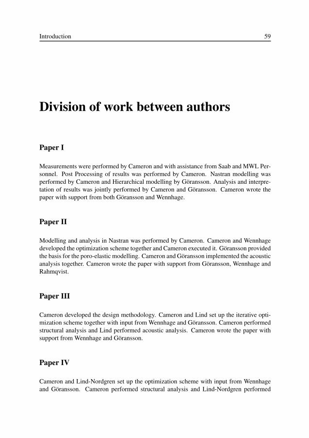
Introduction 59
Division of work between authors
Paper I
Measurements were performed by Cameron and with assistance from Saab and MWL Per-sonnel. Post Processing of results was performed by Cameron. Nastran modelling wasperformed by Cameron and Hierarchical modelling by Göransson. Analysis and interpre-tation of results was jointly performed by Cameron and Göransson. Cameron wrote thepaper with support from both Göransson and Wennhage.
Paper II
Modelling and analysis in Nastran was performed by Cameron. Cameron and Wennhagedeveloped the optimization scheme together and Cameron executed it. Göransson providedthe basis for the poro-elastic modelling. Cameron and Göransson implemented the acousticanalysis together. Cameron wrote the paper with support from Göransson, Wennhage andRahmqvist.
Paper III
Cameron developed the design methodology. Cameron and Lind set up the iterative opti-mization scheme together with input from Wennhage and Göransson. Cameron performedstructural analysis and Lind performed acoustic analysis. Cameron wrote the paper withsupport from Wennhage and Göransson.
Paper IV
Cameron and Lind-Nordgren set up the optimization scheme with input from Wennhageand Göransson. Cameron performed structural analysis and Lind-Nordgren performed

60 Christopher J. Cameron
acoustic analysis. Cameron and Lind-Nordgren compiled the results and wrote the paperwith input from Wennhage and Göransson.
Paper V
Cameron implemented the topology optimization scheme and defined the structural prob-lem. For the iterative structural acoustic optimization, Cameron was responsible for thestructural optimization and Lind-Nordgren for the acoustic optimization. Cameron andLind-Nordgren wrote the paper with input from Wennhage and Görannson.


