University of Twente, Master Sustainable Energy Technology Faculty of Engineering Technology Design of Plywood Biogas Digester By Getachew M.Derese s1046918 [email protected]Supervisors: 1- prof.dr.ir. T.H. van der Meer (UT) 2- Ir. Herman Klein Teeselink (HoSt) Performed at HoSt Bio-energy Installations B.V. Thermen 10 7521 PS Enschede Netherlands Internship Report, July 1 - September 30, 2011
Transcript
University of Twente, Master Sustainable Energy Technology Faculty of Engineering Technology
First of all I would like to give my great appreciation to the HoSt Bio energy installations company which gives me this opportunity to do my internship and experience on the different aspects of sustainable bio energy production. In this regard I would like to thank prof.dr.ir. T.H. van der Meer, who first advised me to work at this company. The director of the company as well as my supervisor Ir. Herman Klein Teeselink is a person that I want to be thankful about his advice and information about my internship problem. For giving me a great practical experience on the different biogas feed stock and methane production analysis, I would like to thank Roy Kleizen and Martin Westerik. Finally all the employees of the company and the students who are doing their internship and master thesis are to be appreciated for their great full approach and willingness to answer my questions.
Design of Plywood Biogas Digester
Getachew.M.Derese 2
Abstract
In a biogas installation, green power is produced from manure and biomass. Because of the optimization and innovation of the biogas industry and the continuously rising energy prices, it is become very interesting to invest in biogas installations. The generated electricity can be sold to energy companies at attractive tariffs for sustainable electricity. The quantity of electricity generated can be guaranteed, making biogas installations attractive investments. A biogas installation also contributes to environmental protection by using sustainable energy resources. For such biogas installation, the digester of the biogas is considered as the main component of the process. Biogas digesters can be made from steel, concrete, plastics etc. but these materials have a problem of either cost, environmental effect or maintenance problems. In this report a 340m3 manure biogas digester will be designed from a different and renewable material. It is designed from an engineered wood product, plywood, which insures a more sustainable production and relatively lower cost with acceptable maintenance. The type and strength of the plywood required, the method of connection of the plywood plates for the required shape of the digester, the horizontal and vertical supports required will be analyzed in this report. The means of integrating the double membrane biogas digester cover is also applied in the report. The digester will be designed in such a way that it is suitable to install at the field within a short period of time and little man power. It is insured to withstand the maximum snow and wind load that could occur for a period of at least 50 years. Key words Plywood, digester, biogas
Design of Plywood Biogas Digester
Getachew.M.Derese 3
Table of Contents 1 Introduction ................................................................................................................................. 5
1.1 Host Bio Energy Installations............................................................................... 5
1.2 Problem Description ............................................................................................ 6
1.3 Objectives and constraints ................................................................................... 7 2 Design and Analysis .................................................................................................................... 8
2.1 Plywood; The engineered wood product .............................................................. 8
2.2 Design requirement of structural plywood............................................................ 8
6.1 Appendix A ....................................................................................................... 45
6.2 Appendix B ....................................................................................................... 46 6.3 Appendix C ....................................................................................................... 47 6.4 Appendix D ....................................................................................................... 48 6.5 Appendix E ....................................................................................................... 49 6.6 Appendix F ........................................................................................................ 50
Design of Plywood Biogas Digester
Getachew.M.Derese 4
6.7 Appendix G ....................................................................................................... 51
Design of Plywood Biogas Digester
Getachew.M.Derese 5
1 Introduction
1.1 Host Bio Energy Installations
Host is a building company specialized in biomass energy installations. It designs and installs biogas digester plants, gasifire plants and wood fired combined heat and power plants. Fundamentally, HoSt is able to generate electricity and heat from biomass using the following technologies:
Biogas plants on farm-and industrial scale
Wood fired CHP-plants
Circulating fluid bed gasifier plants
In the past the company specializes for sustainable biomass energy market. Host founded in 1996 by two mother companies, Holec projects and Stork, both large industrial companies in the Netherlands. Host becomes independent company starting from 1999 with the development of its own technologies for the generation of sustainable energy technologies from biomass which continuous active on it up to present. The company is also involved in feasibility studies, engineering work and legislation for a wide range of consumers, mainly in the energy intensive industry. Host currently has 27 employees at the head quarter in the Netherlands. Besides it has offices and representative in Italy, United Kingdom, Ireland, Canada, North America, Romania, Latvia, Poland, the Check Republic and Slovakia
Design of Plywood Biogas Digester
Getachew.M.Derese 6
1.2 Problem Description
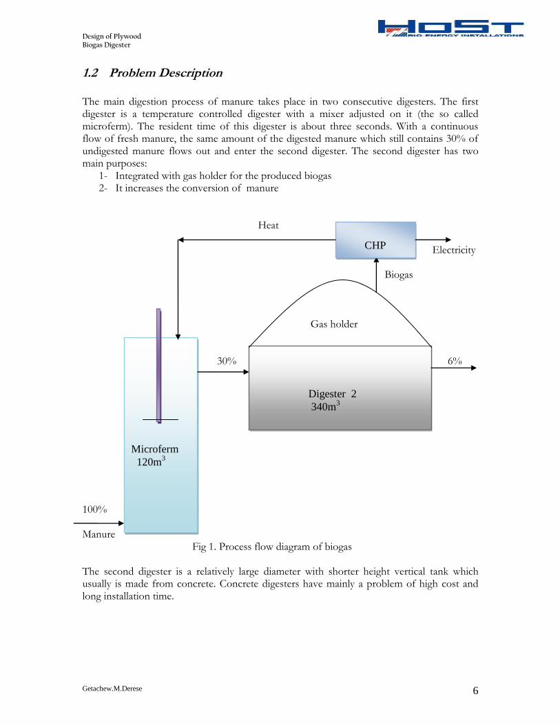
The main digestion process of manure takes place in two consecutive digesters. The first digester is a temperature controlled digester with a mixer adjusted on it (the so called microferm). The resident time of this digester is about three seconds. With a continuous flow of fresh manure, the same amount of the digested manure which still contains 30% of undigested manure flows out and enter the second digester. The second digester has two main purposes:
1- Integrated with gas holder for the produced biogas 2- It increases the conversion of manure
Heat Electricity Biogas Gas holder 30% 6% 100% Manure Fig 1. Process flow diagram of biogas The second digester is a relatively large diameter with shorter height vertical tank which usually is made from concrete. Concrete digesters have mainly a problem of high cost and long installation time.
Microferm
120m3
Digester 2
340m3
CHP
Design of Plywood Biogas Digester
Getachew.M.Derese 7
The given problem is to substitute this digester with cheap and sustainable material with small installation time at the field. The proposed material is structural plywood with the following requirements:
a) The plywood should be strong enough for long period of time b) The digester should be pre-assembled c) It should take a maximum of 2 days with less man power to install at the field d) Should look attractive e) The height of the digester is 4m, which is filled with manure up to 3.5m f) The width of the plates should be between 1 and 2m g) The volume of the digester is 340m3 (with 10% flexibility)
1.3 Objectives and constraints
Objectives: The main objective of the internship is to theoretically proof plywood is used as a substitute for concrete biogas digester. The specific works that will be done include
Specify and analyze the appropriate structural plywood
Stable connection of the plywood plates for the required digester volume
Integrate the previous biogas holder suitable for wooden digester Constraints:
The insulation material is the same as the previous digester which is EPDM rubber. The thickness of the insulation is 1.5mm, the heat transfer from and to the digester will not be analyzed here.
The only design force is the force due to the weight of the manure
The foundation for the digester is not analyzed here.
The materials for the digester cover, which is also used as gas storage, will be the same as the concrete digester.
The selection of the plywood should be towards low price, but a detail analysis will not be done.
Design of Plywood Biogas Digester
Getachew.M.Derese 8
2 Design and Analysis
2.1 Plywood; The engineered wood product
Plywood is a type of manufactured timber made from thin sheets of wood veneer (plywood layers). It is one of the most widely used wood products with flexible, inexpensive, workable and reusable product. It is used instead of plain wood because of its resistance to cracking, shrinkage and twisting and its general high degree of strength. The main advantage of plywood in comparison to solid wood is:
Less variable mechanical properties
Better dimensional stability
A higher utilization level of a raw timber Plywood is often used in the construction of walls during which axial load is inevitably applied to the wall. It is manufactured with an odd number of thin sheets of wood or veneers which are glued together under heat and pressure. The number of these veneers to be odd is required to maintain the same grain facing in the same direction for the bottom and top sheets. That is the reason why the plywood is strong in all directions opposed to standard wood which is strong only across the grain. The structural plywood's that are commonly used in Europe are:
American construction and industrial plywood
Canadian soft wood plywood and Douglas fir plywood
Finish birch plywood
British softwood plywood The standard plywood sizes available are 1200mm x 2400mm or 1220mm x 2440. But other dimensions are usually possible through special order. The structural properties and strength of plywood depend mainly on the number of thickness of each ply, the species and grade and arrangement of the individual plies. As with timber the structural properties of plywood are functions of applied stresses and, the direction with respect to grain direction of face ply and the duration of load. If the plywood is subjected to bending in two different planes, the stress values will also differ which is important to differentiate them during design.
2.2 Design requirement of structural plywood
Since the bottom of the digester is at a maximum load, the design is based on the maximum pressure at the bottom which acts normal to the grain direction of the plywood. The design strength capacity and stiffness of structural plywood, weather loaded normal to the plane or parallel to the plain, is calculated using standard principles of engineering mechanics. Design capacities are then determined by multiplying the characteristic property by
Section property
Capacity property
In-service factors The strength limit state condition is then satisfied when the design capacity of the structural plywood exceeds the design load effects from the factored loads. The corresponding section modulus and second moment of area for each cross section is pre-calculated and tabulated per plywood type.
Design of Plywood Biogas Digester
Getachew.M.Derese 9
2.2.1 Modification factors
a) Capacity factor (Φ)
It is a material capacity factor which allows viability in material strength and the consequence of failure. The capacity factor for structural plywood is specified in the Australian standard and the European standard. The biogas digester is considered to be a primary structural element other than house. Therefore the capacity factor is selected to be 0.8.
b) Load duration factor (k1)
The load duration factor allows for the time dependent nature of the strength of plywood. This is based on the principle that plywood subjected to a short term load without failure may fail over time if the load is sustained. Thus the k1 factor allows for the reduction in the strength capacity of the plywood member when subjected to a long term loads. Since the manure load on the biogas digester is a permanent load, for a design life time of 50 years, the load duration factor is selected to be 0.57.
c) Moisture content factor (k19) The moisture content factor is used to modify plywood strength capacity to allow for the reduction in strength that if for a 12 month period the average moisture content of the plywood in service remains higher than 15%. Example for this condition is applications in continuously humid environments and the case where the plywood is continuously sprayed with water. For other conditions it is taken as 1. For the digester case it is also considered 1 because there is no condition for the digester to operate with a moisture content of more than 15% continuously through the year.
d) Plywood assembly factor (g19) The g19 factor affects both strength and stiffness and varies depending on weather the plywood is loaded in plane or normal to the face. For the plywood which is loaded normal to the plane of the plywood panel, the assembly factor is always 1. For the same condition, the shear strength calculation will be done with the assembly factor of 0.4.
e) Serviceability modification (j2) This factor allows for the time dependent increase in deformation of plywood components under constant bending, compression and shear loads. The magnitude of the creep deformation in plywood products increases with longer term loads and higher moisture content. For a load duration of one year and above the duration of load factor for creep deformation is 2. Since the load duration in our digester is more than one year the factor is selected to be 2.
Design of Plywood Biogas Digester
Getachew.M.Derese 10
2.2.2 Design action effects
a) Bending criteria (established minimum fbZp) For fb is the characteristic bending strength normal to the plane of the plane
Zp is the plywood section modulus Mp is the design capacity in bending (the maximum bending moment that could occur) M*
p is the design action effect in bending
pp MM 5.1*
The strength limit state is satisfied when
*
pp MM
And ][19191 pbp ZfgkkM
*
19191 ][ ppb MZfgkk
19191
*
][gkk
MZf
p
pb
Based on the minimum ][ pbZf required, the strength and thickness of the plywood is
selected from available data of structural plywood. The selected plywood should have greater value than the minimum required.
b) Shear criteria (established minimum fsAs) For fs the characteristic plane shear strength normal to the plane of the panel As the shear plane area Vp design capacity on shear (maximum shear force created) Vp
* the design action effect in shear
pp VV 5.1*
The strength limit state is satisfied when
*
pp VV
And ][19191 ssp AfgkkV
*
19191 ][ pss VAfgkk
19191
*
][gkk
VAf
p
ss
Based on the minimum ][ ss Af required, the strength and thickness of the plywood is
selected from available data of structural plywood. The selected plywood should have greater value than the minimum required.
Design of Plywood Biogas Digester
Getachew.M.Derese 11
c) Deflection criteria (established minimum EI) Required criteria
itdeflectionjjdeflectionCalculated lim** 192
max192
*
max gj
Substituting the maximum allowable deflection value for *
max and express max in terms of
EI based on the maximum deflection of the plate arrangement, then the type and thickness of the plywood is selected from structural plywood data. Finally the selected plywood should satisfy all the three criteria’s above. The selection of the plywood can be in any direction from the plywood to the design or the other way round.
2.2.3 Specification of Digester plywood
Since the standard dimensions of plywood are not fitted with the required digester size, a special order has to be made to get the required dimension of plates (4000 by 1000-2000) mm. To be cost effective the plywood that is imported in the Netherlands and distributed to the country is selected. Specification: Company: International plywood BV, Netherlands Name: Superfloor-giant, it is available in extra large dimensions Species: Finnish Birch plywood Quality: through and through birch veneers of 1.5mm Glue bonding: WBP- in accordance with EN 314-class three exterior, DIN 68705/BFU 100/BS 6566 WBP Thickness: any thickness at request Dimension: Up to 1800x4000mm can be delivered at request Density (mean): approx, 680kg/m3
Density (characteristics): 630kg/m3 Therefore this plywood with the extra large dimension of 1800x4000mm is selected. Properties and specifications of this plywood are given on Hand book of Finnish plywood.
Design of Plywood Biogas Digester
Getachew.M.Derese 12
2.2.4 Number of plates required
Diameter of the digester
Assuming the digester as a uniform cylindrical pressure vessel, the volume is given by,
hrV 2
4*340 2r , r= 5.2m Dimension of the plywood plate L=4000 mm W-1800mm For a standard width of 1800mm (1.8m) the required number of plates to achieve the required volume of the digester is determined. For n-sided polygon the area with a length of w is given by:
)cot(4
1 2
nnwA
With the internal angle of
0
int 180*2
1
n
The volume of the cylinder if it was a uniform cylindrical tank is given by:
AAhV *4*
22 85* mrA Since the height of the digester remains constant the area of the new digester should be near to 85m2. If we choose n=18, the area of the digester becomes
22 687.82)18
cot(8.1*18*4
1mA
The corresponding volume is then 375.330687.82*4* mAhV
The deviation from the required volume of the digester is:
%100*%old
newold
V
VVdeviation
%75.2%100*340
75.330340%
deviation
Less than 10% deviation from the required volume of the digester is acceptable. Therefore the required number of plywood plates is 18. The internal angle of the plates (the angle that the two plates should make when join)
00
int 160180*18
21
Design of Plywood Biogas Digester
Getachew.M.Derese 13
2.2.5 Plywood biogas digester concept
The 18 plywood plates with the specified length and width should be connected together making an equally sided Octakaidecagon (18 sided polygon). To do this the corresponding two plates should be connected in such a way that the angle between them makes 160 degrees. The plates are then connected vertically with a certain type of connector which acts as a support as well. Among the different means of connecting two plywood plates, the best method is selected to be connecting them using a metal frame and mechanical bolt. One possibility was connecting the plywood plates by glue, even if this was not applicable here. The first reason is because of its weak strength, glue connection is used for light loaded plywood connections. The second reason is the connection should also be used as a support, the digester walls will be designed base on the plates that are supported at the two ends. Therefore a metal frame with the strength of withstanding the exerted pressure is used for the connection of this plywood's. It will be checked latter that the plywood plates need a vertical and horizontal metal support. The supports will be designed with the required strength, thickness and span length. As the main plate connector, the supports will be connected to the plywood with a mechanical fastener. The mechanical fasteners in this case bolts are the cheapest, strongest, and easy way of installing and uninstalling connection methods. The insulation of the material with a thickness of 1.5mm is bolted with the metal frames and the plywood. This has an advantage of insuring gas tightness since it is acted as a gasket. The horizontal supports will be also connected to the plywood by mechanical bolts with a different span length depending on the vertical load. The horizontal support at the top is actually not subjected to a load due to the fluid. It will be used as a connection means for the biogas covers and the wire ropes for the protection of the inside membrane falling down to the digestate during gas utilization. For the stability of the connection and the attractiveness of the digester, all the bolt heads are projected to the outside. The horizontal connectors are in single shear and are bolted outside of the digester. It runs from one edge of the main connector to the other, in such a way that there is no overlapping. The vertical supporters are placed inside the digester otherwise they could overlap with the horizontal supports. They are bolted to the plywood and the inside insulation material with a bolt with its head projected outside.
Design of Plywood Biogas Digester
Getachew.M.Derese 14
2.3 Mechanical Design of digester walls
2.3.1 Maximum design load
The main load to be considered in the design of atmospheric liquid storage tanks is the hydrostatic pressure of the liquid. But the tanks must also be designed to withstand wind loading and in some locations the weight of the snow in the tank roof. The liquid density should be taken as that of water unless the process liquid has a greater density. The secondary biogas digester has no external or internal pressure load. Besides the maximum operating temperature is 40 degree Celsius which don’t need any thermal design. In that case the digester is considered as a liquid storage tank. Since the manure which is mixed with water has a density less than water, the design liquid is water through the analysis. The pressure is zero at the top of the liquid and increases linearly to the maximum at the bottom.
)(5.3
335.34kpahp
At the bottom
kpaghP 335.345.3*81.9*1000 This is the maximum pressure due to the weight
of the manure. The only load applied normal to the walls is the pressure due to the weight of the manure;
kpaP 335.34max
The design load of the digester is therefore this maximum pressure which acts at the bottom of the digester.
Design of Plywood Biogas Digester
Getachew.M.Derese 15
2.3.2 Vertical support requirement
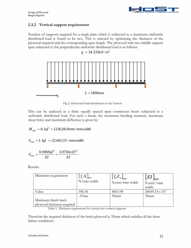
Number of supports required for a single plate which is subjected to a maximum uniformly distributed load is found to be two. This is selected by optimizing the thickness of the plywood required and the corresponding span length. The plywood with two middle support span subjected to the perpendicular uniformly distributed load is as follows:
2/335.34 mkNq
X mmL 1800
Fig 2, Horizontal load distribution at the bottom
This can be analyzed as a three equally spaced span continuous beam subjected to a uniformly distributed load. For such a beam, the maximum bending moment, maximum shear force and maximum deflection is given by:
widthmmNmmqlM /06.12361.0 2
max
widthmmNqlV /6611.221.1max
EI
x
EI
ql 104
max
100704.30069.0
Results:
Minimum requirement minss Af
N/mm width
minpbZf
N.mm/mm width
minEI
N.mm2/mm width
Value 186.36 4065.98 20649.15 x 103
Minimum finish birch plywood thickness required
21mm 30mm 35mm
Table 1, Thickness requirement for vertical two vertical supports
Therefore the required thickness of the birch plywood is 35mm which satisfies all the three failure conditions.
Design of Plywood Biogas Digester
Getachew.M.Derese 16
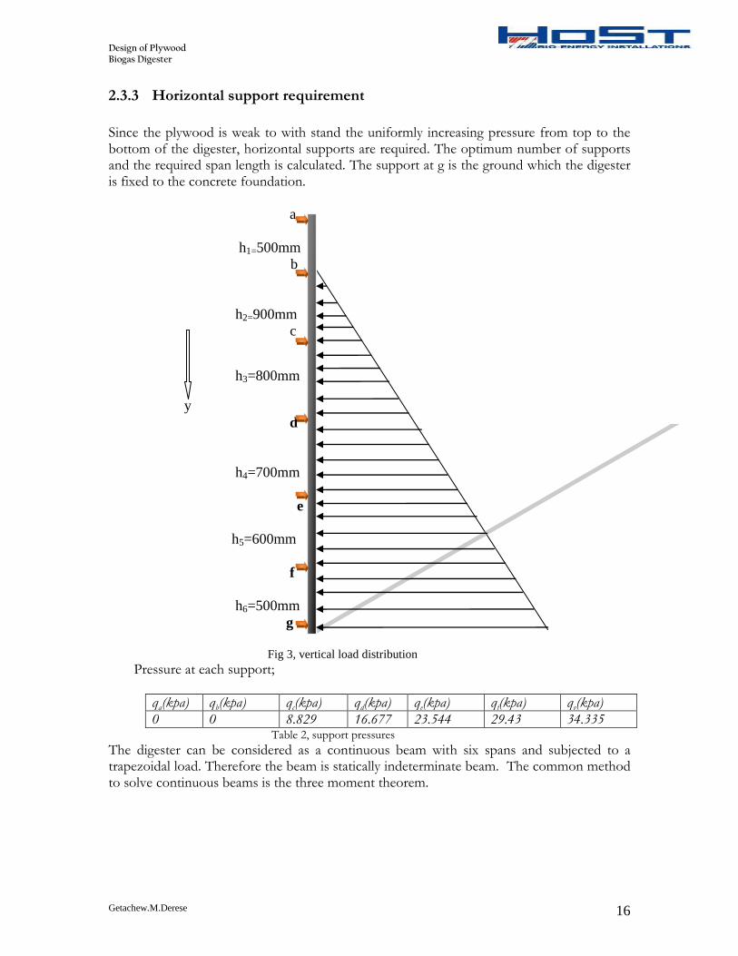
2.3.3 Horizontal support requirement
Since the plywood is weak to with stand the uniformly increasing pressure from top to the bottom of the digester, horizontal supports are required. The optimum number of supports and the required span length is calculated. The support at g is the ground which the digester is fixed to the concrete foundation.
a
h1=500mm
b
h2=900mm
c
h3=800mm
y
d
h4=700mm
e
h5=600mm
f
h6=500mm
g
Fig 3, vertical load distribution Pressure at each support;
The digester can be considered as a continuous beam with six spans and subjected to a trapezoidal load. Therefore the beam is statically indeterminate beam. The common method to solve continuous beams is the three moment theorem.
Design of Plywood Biogas Digester
Getachew.M.Derese 17
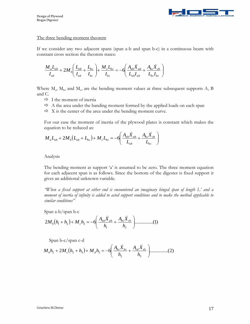
The three bending moment theorem If we consider any two adjacent spans (span a-b and span b-c) in a continuous beam with constant cross section the theorem states:
bcbc
cbbc
abab
abab
bc
bcc
bc
bc
ab
abb
ab
aba
IL
XA
IL
XA
I
LM
I
L
I
LM
I
LM
62
Where Ma, Mb, and Mc, are the bending moment values at three subsequent supports A, B and C.
I the moment of inertia
A the area under the banding moment formed by the applied loads on each span
X is the center of the area under the bending moment curve. For our case the moment of inertia of the plywood plates is constant which makes the equation to be reduced as:
bc
cbbc
ab
ababbccbcabbaba
L
XA
L
XALMLLMLM
62
Analysis The bending moment at support ‘a’ is assumed to be zero. The three moment equation for each adjacent span is as follows. Since the bottom of the digester is fixed support it gives an additional unknown variable. “When a fixed support at either end is encountered an imaginary hinged span of length L’ and a moment of inertia of infinity is added to acted support conditions and to make the method applicable to similar conditions” Span a-b/span b-c
)1.....(..........6221
221
h
XA
h
XAhMhhM cbbcabab
cb
Span b-c/span c-d
)2.....(..........62
32
3322
h
XA
h
XAhMhhMhM dccdbcbc
dcb
Design of Plywood Biogas Digester
Getachew.M.Derese 18
Span c-d/span d-e
)3.....(..........6243
4433
h
XA
h
XAhMhhMhM ededcdcd
edc
Span d-e/ span e-f
)4.....(..........6254
5544
h
XA
h
XAhMhhMhM
feefdedeedd
Span e-f/ span f-g
)5.....(..........6265
6655
h
XA
h
XAhMhhMhM
gffgefef
gfe
Span f-g/span g-g’ (g-g’ imaginary span)
)6.....(..........626
46
h
XAhMhM
fgfg
gf
We have six equations and six unknowns (bending moment at each support). The area under the bending moment curve and the center for each span is determined. Span a-b is not loaded so it doesn’t have a bending moment area. Span b-c is subjected to a uniformly increasing load from zero to qc whose bending moment and the area under the bending moment curve is given by:
22
22
23yh
h
yqM c
ba , 12
2
2hqA c
cb
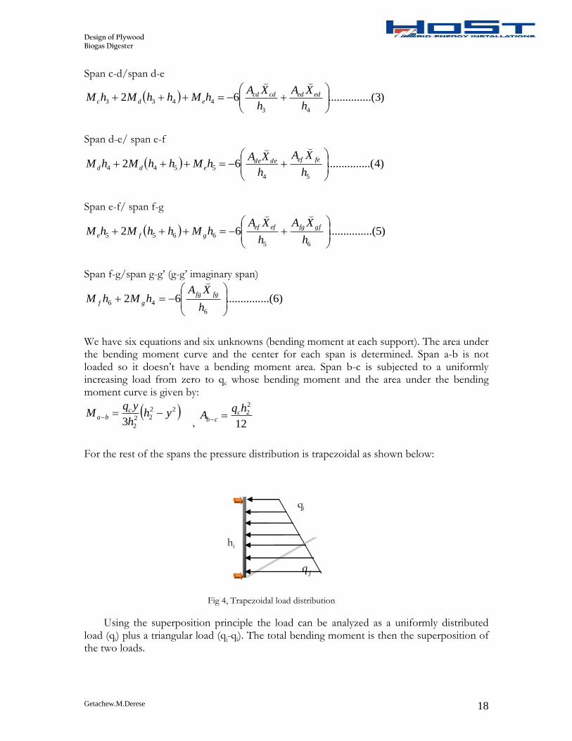
For the rest of the spans the pressure distribution is trapezoidal as shown below:
qi
hi
jq
Fig 4, Trapezoidal load distribution
Using the superposition principle the load can be analyzed as a uniformly distributed load (qi) plus a triangular load (qj-qi). The total bending moment is then the superposition of the two loads.
Design of Plywood Biogas Digester
Getachew.M.Derese 19
yh
yqyhy
h
qqM i
ii
i
ij
ij
23
22
2
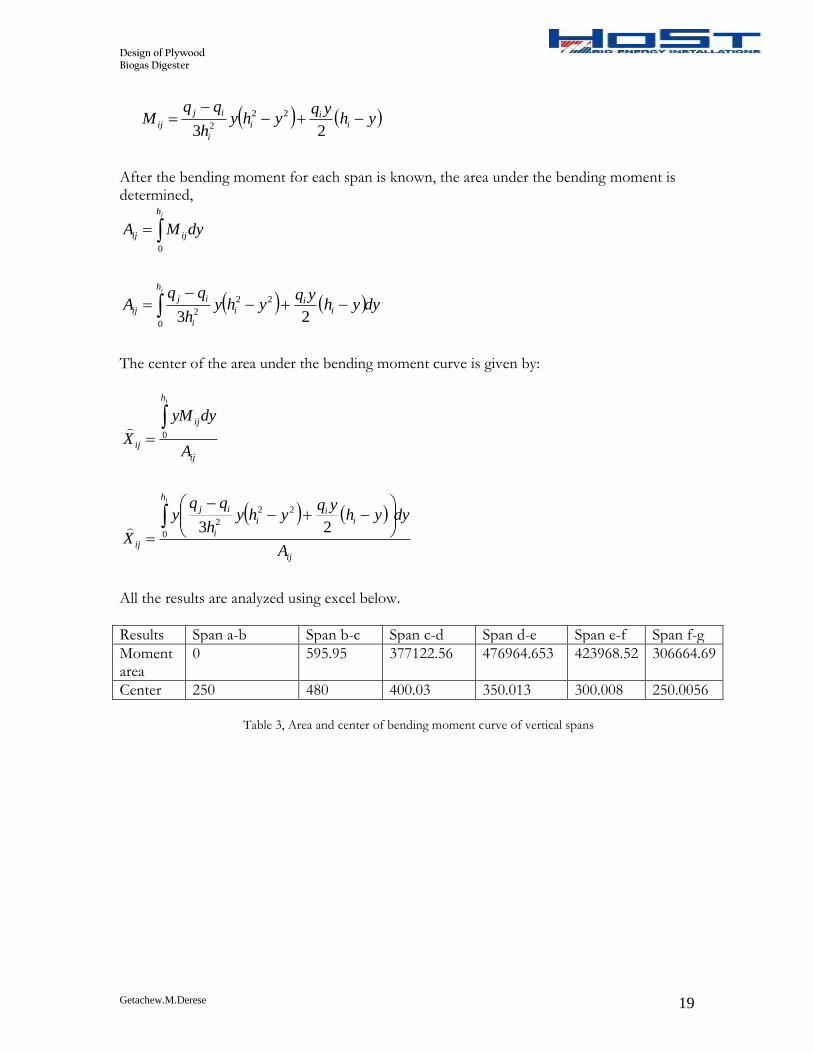
After the bending moment for each span is known, the area under the bending moment is determined,
ih
ijij dyMA0
dyyhyq
yhyh
qqA
ih
ii
i
i
ij
ij
0
22
2 23
The center of the area under the bending moment curve is given by:
Table 3, Area and center of bending moment curve of vertical spans
Design of Plywood Biogas Digester
Getachew.M.Derese 20
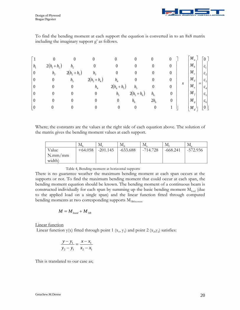
To find the bending moment at each support the equation is converted in to an 8x8 matrix including the imaginary support g’ as follows.
Where; the constants are the values at the right side of each equation above. The solution of the matrix gives the bending moment values at each support.
Table 4, Bending moment at horizontal supports
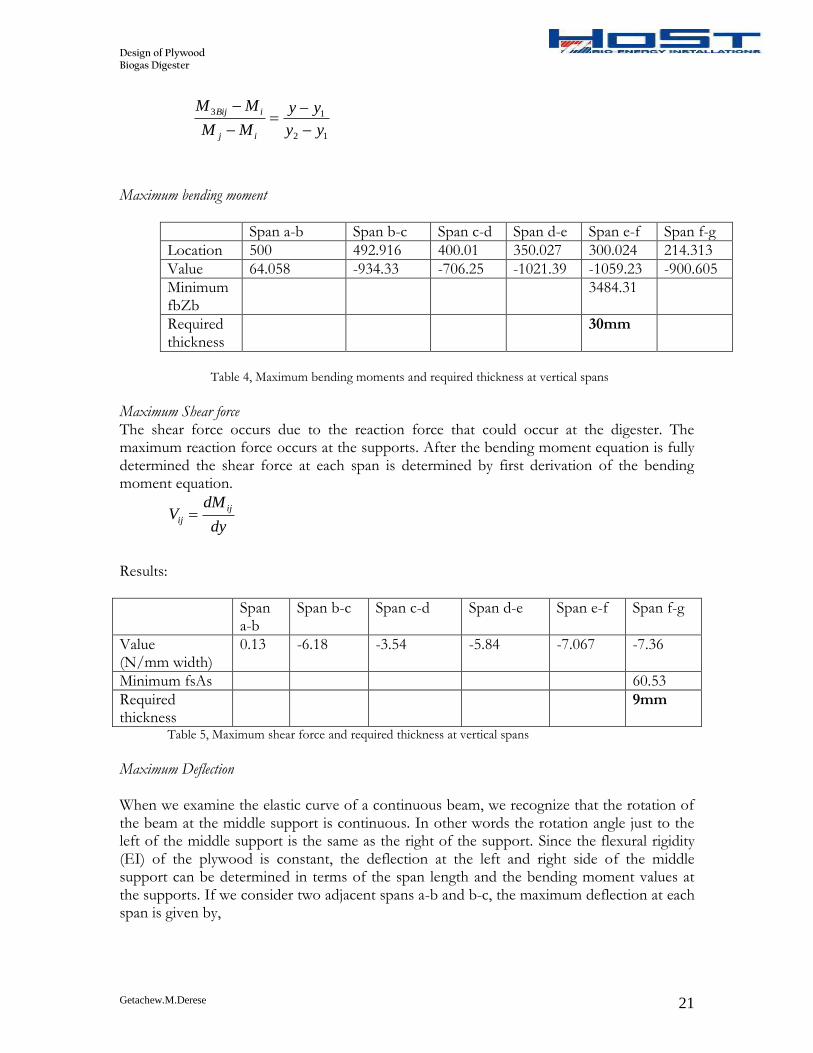
There is no guarantee weather the maximum bending moment at each span occurs at the supports or not. To find the maximum bending moment that could occur at each span, the bending moment equation should be known. The bending moment of a continuous beam is constructed individually for each span by summing up the basic bending moment Mload (due to the applied load on a single span) and the linear function fitted through computed bending moments at two corresponding supports M3Btheorem
Bload MMM 3
Linear function Linear function y(x) fitted through point 1 (x1, y1) and point 2 (x2,y2) satisfies:
Value 64.058 -934.33 -706.25 -1021.39 -1059.23 -900.605
Minimum fbZb
3484.31
Required thickness
30mm
Table 4, Maximum bending moments and required thickness at vertical spans
Maximum Shear force The shear force occurs due to the reaction force that could occur at the digester. The maximum reaction force occurs at the supports. After the bending moment equation is fully determined the shear force at each span is determined by first derivation of the bending moment equation.
dy
dMV
ij
ij
Results:
Span a-b
Span b-c Span c-d Span d-e Span e-f Span f-g
Value (N/mm width)
0.13 -6.18 -3.54 -5.84 -7.067 -7.36
Minimum fsAs 60.53
Required thickness
9mm
Table 5, Maximum shear force and required thickness at vertical spans
Maximum Deflection
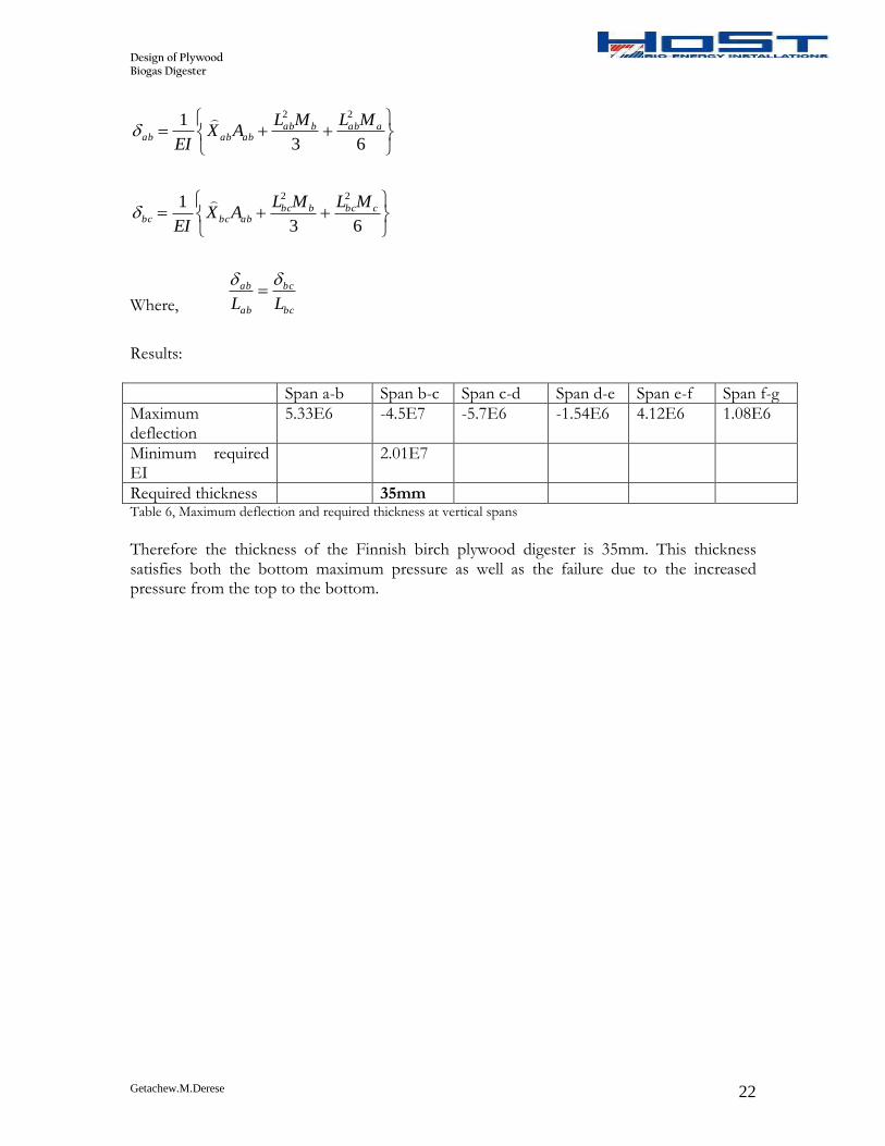
When we examine the elastic curve of a continuous beam, we recognize that the rotation of the beam at the middle support is continuous. In other words the rotation angle just to the left of the middle support is the same as the right of the support. Since the flexural rigidity (EI) of the plywood is constant, the deflection at the left and right side of the middle support can be determined in terms of the span length and the bending moment values at the supports. If we consider two adjacent spans a-b and b-c, the maximum deflection at each span is given by,
Required thickness 35mm Table 6, Maximum deflection and required thickness at vertical spans
Therefore the thickness of the Finnish birch plywood digester is 35mm. This thickness satisfies both the bottom maximum pressure as well as the failure due to the increased pressure from the top to the bottom.
Design of Plywood Biogas Digester
Getachew.M.Derese 23
2.4 Plate connector and support design
2.4.1 Design of vertical supports
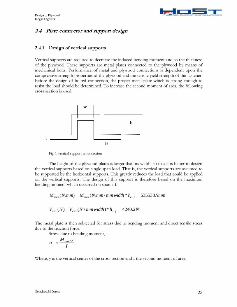
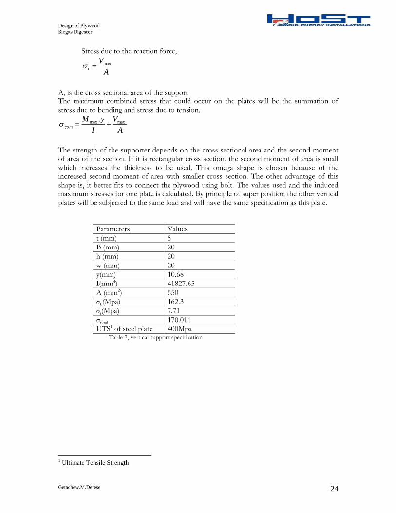
Vertical supports are required to decrease the induced bending moment and so the thickness of the plywood. These supports are metal plates connected to the plywood by means of mechanical bolts. Performance of metal and plywood connections is dependent upon the compressive strength properties of the plywood and the tensile yield strength of the fastener. Before the design of bolted connection, the proper metal plate which is strong enough to resist the load should be determined. To increase the second moment of area, the following cross section is used. w h t B
Fig 5, vertical support cross section
The height of the plywood plates is larger than its width, so that it is better to design
the vertical supports based on single span load. That is, the vertical supports are assumed to be supported by the horizontal supports. This greatly reduces the load that could be applied on the vertical supports. The design of this support is therefore based on the maximum bending moment which occurred on span e-f.
NmmhwidthmmmmNMmmNM fe 635538*/.().( maxmax
NhwidthmmNVNV fe 2.4240*)/()( maxmax
The metal plate is then subjected for stress due to bending moment and direct tensile stress due to the reaction force.
Stress due to bending moment,
I
yMb
.max
Where, y is the vertical center of the cross section and I the second moment of area.
Design of Plywood Biogas Digester
Getachew.M.Derese 24
Stress due to the reaction force,
A
Vt
max
A, is the cross sectional area of the support. The maximum combined stress that could occur on the plates will be the summation of stress due to bending and stress due to tension.
A
V
I
yMcom
maxmax .
The strength of the supporter depends on the cross sectional area and the second moment of area of the section. If it is rectangular cross section, the second moment of area is small which increases the thickness to be used. This omega shape is chosen because of the increased second moment of area with smaller cross section. The other advantage of this shape is, it better fits to connect the plywood using bolt. The values used and the induced maximum stresses for one plate is calculated. By principle of super position the other vertical plates will be subjected to the same load and will have the same specification as this plate.
Parameters Values
t (mm) 5
B (mm) 20
h (mm) 20
w (mm) 20
y(mm) 10.68
I(mm4) 41827.65
A (mm2) 550
σb(Mpa) 162.3
σt(Mpa) 7.71
σtotal 170.011
UTS1 of steel plate 400Mpa Table 7, vertical support specification
1 Ultimate Tensile Strength
Design of Plywood Biogas Digester
Getachew.M.Derese 25
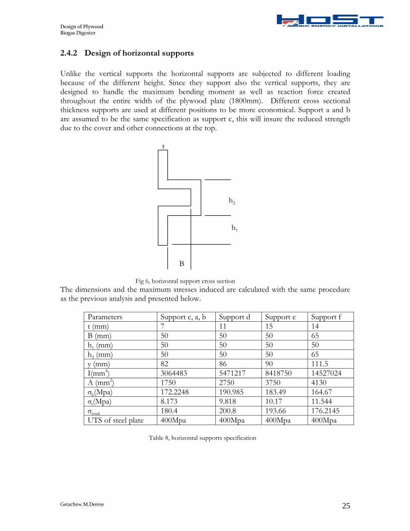
2.4.2 Design of horizontal supports
Unlike the vertical supports the horizontal supports are subjected to different loading because of the different height. Since they support also the vertical supports, they are designed to handle the maximum bending moment as well as reaction force created throughout the entire width of the plywood plate (1800mm). Different cross sectional thickness supports are used at different positions to be more economical. Support a and b are assumed to be the same specification as support c, this will insure the reduced strength due to the cover and other connections at the top. t h2 h1
B Fig 6, horizontal support cross section
The dimensions and the maximum stresses induced are calculated with the same procedure as the previous analysis and presented below.
Parameters Support c, a, b Support d Support e Support f
t (mm) 7 11 15 14
B (mm) 50 50 50 65
h1 (mm) 50 50 50 50
h2 (mm) 50 50 50 65
y (mm) 82 86 90 111.5
I(mm4) 3064483 5471217 8418750 14527024
A (mm2) 1750 2750 3750 4130
σb(Mpa) 172.2248 190.985 183.49 164.67
σt(Mpa) 8.173 9.818 10.17 11.544
σtotal 180.4 200.8 193.66 176.2145
UTS of steel plate 400Mpa 400Mpa 400Mpa 400Mpa
Table 8, horizontal supports specification
Design of Plywood Biogas Digester
Getachew.M.Derese 26
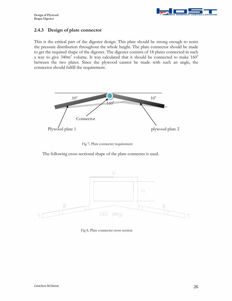
2.4.3 Design of plate connector
This is the critical part of the digester design. This plate should be strong enough to resist the pressure distribution throughout the whole height. The plate connector should be made to get the required shape of the digester. The digester consists of 18 plates connected in such a way to give 340m3 volume. It was calculated that it should be connected to make 1600 between the two plates. Since the plywood cannot be made with such an angle, the connector should fulfill the requirement.
The following cross sectional shape of the plate connecter is used.
Fig 8, Plate connecter cross section
Design of Plywood Biogas Digester
Getachew.M.Derese 27
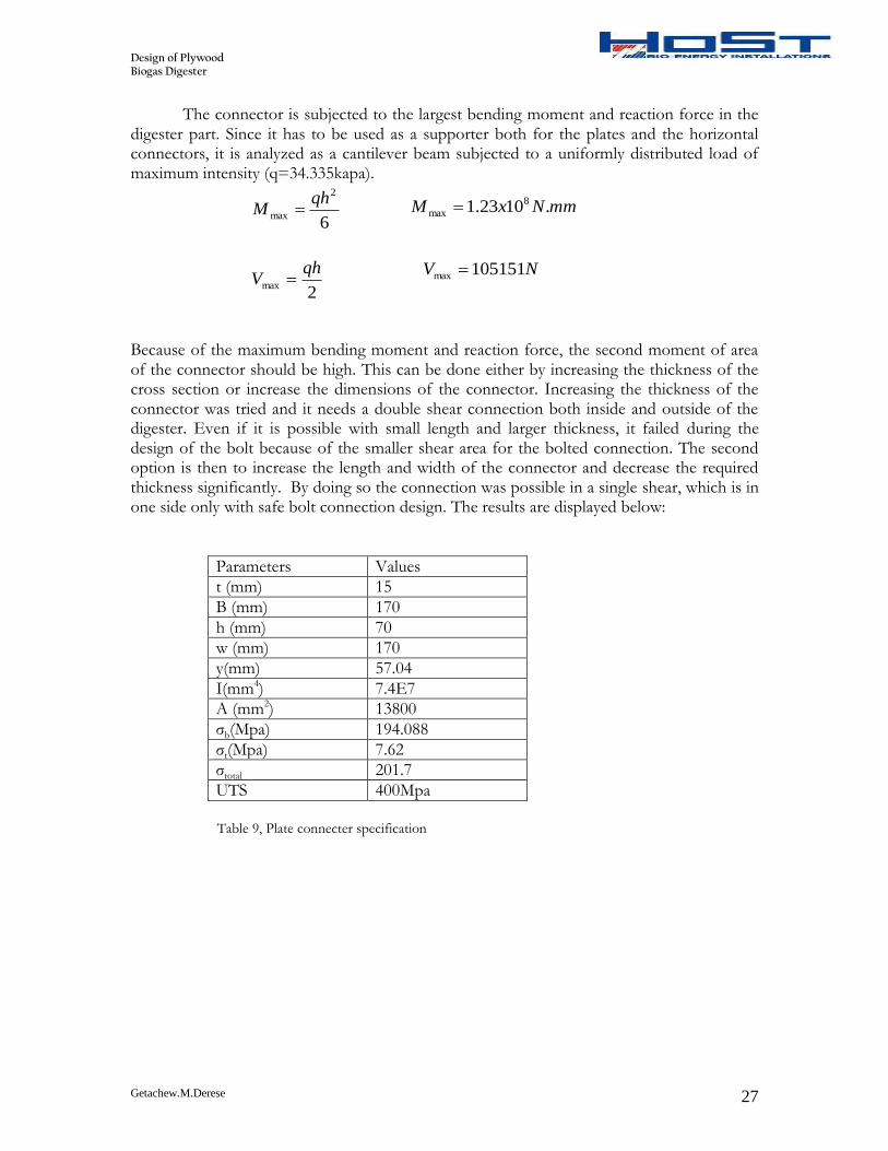
The connector is subjected to the largest bending moment and reaction force in the digester part. Since it has to be used as a supporter both for the plates and the horizontal connectors, it is analyzed as a cantilever beam subjected to a uniformly distributed load of maximum intensity (q=34.335kapa).
Because of the maximum bending moment and reaction force, the second moment of area of the connector should be high. This can be done either by increasing the thickness of the cross section or increase the dimensions of the connector. Increasing the thickness of the connector was tried and it needs a double shear connection both inside and outside of the digester. Even if it is possible with small length and larger thickness, it failed during the design of the bolt because of the smaller shear area for the bolted connection. The second option is then to increase the length and width of the connector and decrease the required thickness significantly. By doing so the connection was possible in a single shear, which is in one side only with safe bolt connection design. The results are displayed below:
Parameters Values
t (mm) 15
B (mm) 170
h (mm) 70
w (mm) 170
y(mm) 57.04
I(mm4) 7.4E7
A (mm2) 13800
σb(Mpa) 194.088
σt(Mpa) 7.62
σtotal 201.7
UTS 400Mpa
Table 9, Plate connecter specification
6
2
max
qhM
2max
qhV
mmNxM .1023.1 8
max
NV 105151max
Design of Plywood Biogas Digester
Getachew.M.Derese 28
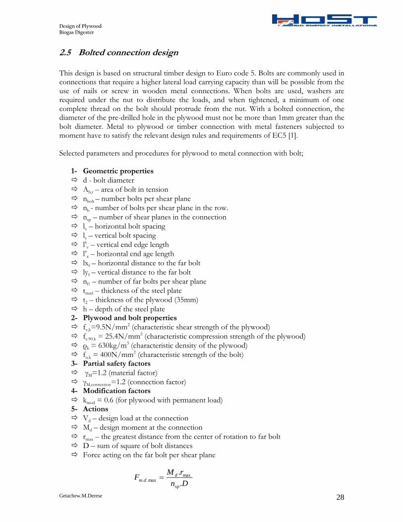
2.5 Bolted connection design
This design is based on structural timber design to Euro code 5. Bolts are commonly used in connections that require a higher lateral load carrying capacity than will be possible from the use of nails or screw in wooden metal connections. When bolts are used, washers are required under the nut to distribute the loads, and when tightened, a minimum of one complete thread on the bolt should protrude from the nut. With a bolted connection, the diameter of the pre-drilled hole in the plywood must not be more than 1mm greater than the bolt diameter. Metal to plywood or timber connection with metal fasteners subjected to moment have to satisfy the relevant design rules and requirements of EC5 [1]. Selected parameters and procedures for plywood to metal connection with bolt;
1- Geometric properties
d - bolt diameter
Ab,t – area of bolt in tension
nbolt – number bolts per shear plane
nb - number of bolts per shear plane in the row.
nsp – number of shear planes in the connection
lx – horizontal bolt spacing
ly – vertical bolt spacing
l’v – vertical end edge length
l’x – horizontal end age length
lxf – horizontal distance to the far bolt
lyf – vertical distance to the far bolt
nl1 – number of far bolts per shear plane
tsteel – thickness of the steel plate
t2 – thickness of the plywood (35mm)
h – depth of the steel plate 2- Plywood and bolt properties
fv,k=9.5N/mm2 (characteristic shear strength of the plywood)
fc.90.k = 25.4N/mm2 (characteristic compression strength of the plywood)
ρk = 630kg/m3 (characteristic density of the plywood)
fu.k = 400N/mm2 (characteristic strength of the bolt) 3- Partial safety factors
kmod = 0.6 (for plywood with permanent load) 5- Actions
Vd – design load at the connection
Md – design moment at the connection
rmax – the greatest distance from the center of rotation to far bolt
D – sum of square of bolt distances
Force acting on the far bolt per shear plane
Dn
rMF
sp
ddm
.
. maxmax..
Design of Plywood Biogas Digester
Getachew.M.Derese 29
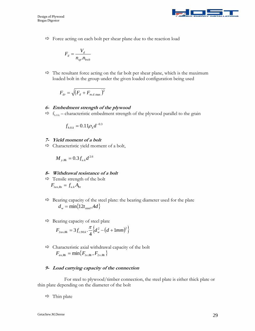
Force acting on each bolt per shear plane due to the reaction load
boltsp
dd
nn
VF
.
The resultant force acting on the far bolt per shear plane, which is the maximum loaded bolt in the group under the given loaded configuration being used
2max..dmddr FFF
6- Embedment strength of the plywood fh.0.k – characteristic embedment strength of the plywood parallel to the grain
3.0
.0. 11.0 df kkh
7- Yield moment of a bolt Characteristic yield moment of a bolt,
6.2
.. 3.0 dfM kuRky
8- Withdrawal resistance of a bolt Tensile strength of the bolt
btkuRxax AfF .,1
Bearing capacity of the steel plate: the bearing diameter used for the plate
dtd steelw 4,12min
Bearing capacity of steel plate
22
.90..2 14
.3 mmddfF wkcRkax
Characteristic axial withdrawal capacity of the bolt
RkxRkxRkax FFF .2.1, ,min
9- Load carrying capacity of the connection For steel to plywood/timber connection, the steel plate is either thick plate or thin plate depending on the diameter of the bolt
Thin plate
Design of Plywood Biogas Digester
Getachew.M.Derese 30
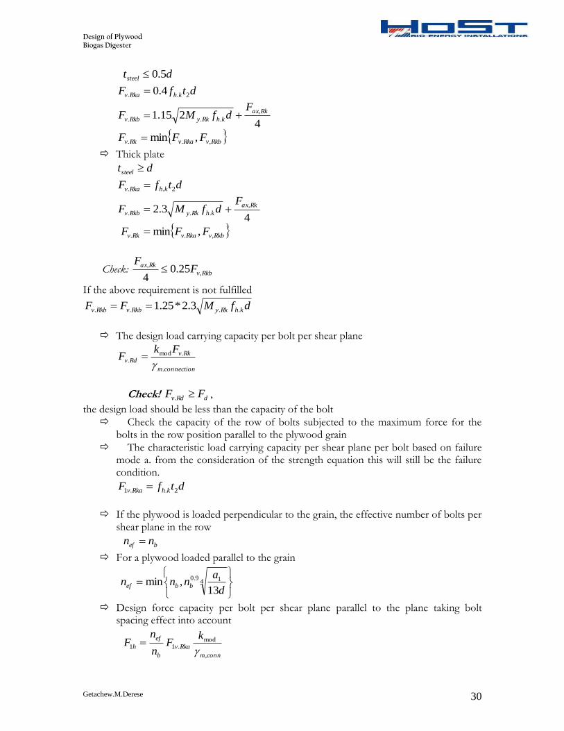
dtsteel 5.0
dtfF khRkav 2.. 4.0
4215.1
,
...
Rkax
khRkyRkbv
FdfMF
RkbvRkavRkv FFF ,.. ,min
Thick plate
dtsteel
dtfF khRkav 2..
43.2
,
...
Rkax
khRkyRkbv
FdfMF
RkbvRkavRkv FFF ,.. ,min
Check: Rkbv
RkaxF
F,
,25.0
4
If the above requirement is not fulfilled
dfMFF khRkyRkbvRkbv .... 3.2*25.1
The design load carrying capacity per bolt per shear plane
connectionm
RkvRdv
FkF
.
.mod.
Check! dRdv FF . ,
the design load should be less than the capacity of the bolt
Check the capacity of the row of bolts subjected to the maximum force for the bolts in the row position parallel to the plywood grain
The characteristic load carrying capacity per shear plane per bolt based on failure mode a. from the consideration of the strength equation this will still be the failure condition.
dtfF khRkav 2..1
If the plywood is loaded perpendicular to the grain, the effective number of bolts per shear plane in the row
bef nn
For a plywood loaded parallel to the grain
4 19.0
13,min
d
annn bbef
Design force capacity per bolt per shear plane parallel to the plane taking bolt spacing effect into account
connm
Rkav
b
ef
h
kF
n
nF
,
mod.11
Design of Plywood Biogas Digester
Getachew.M.Derese 31
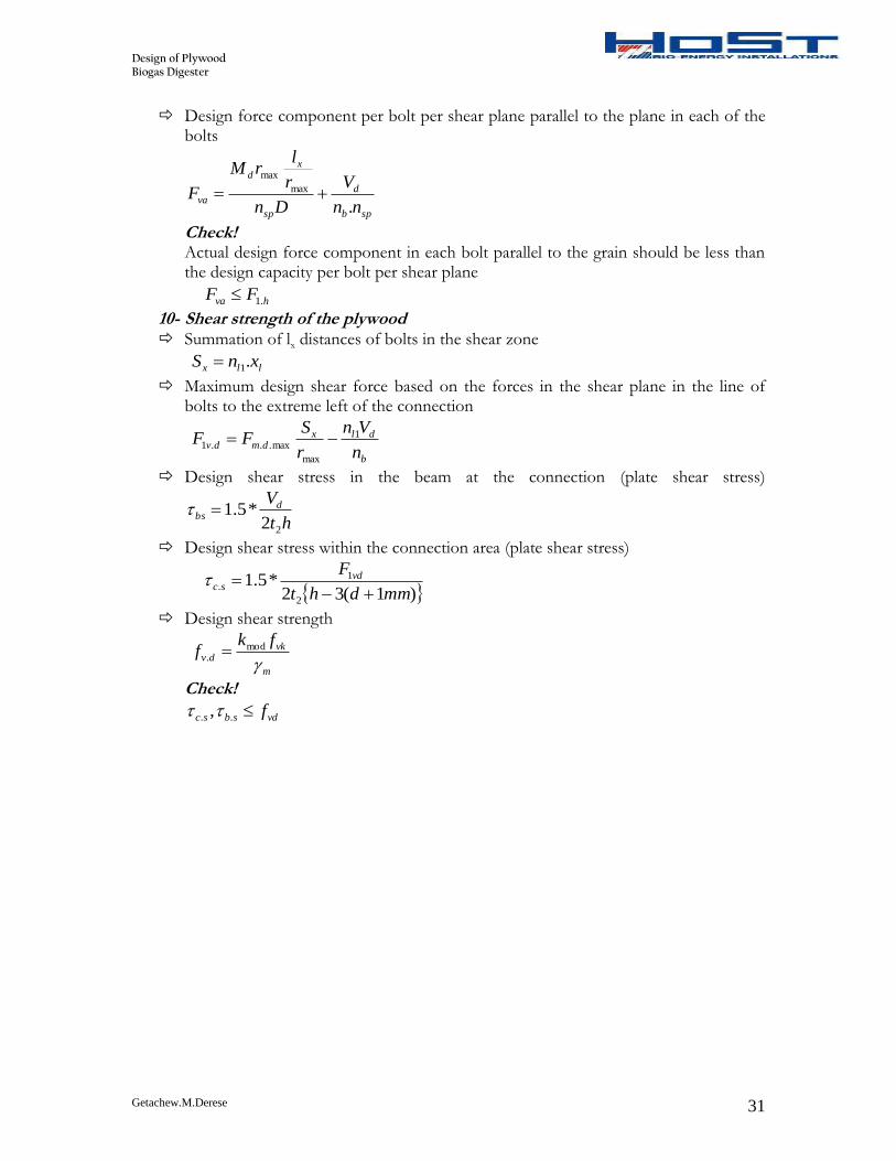
Design force component per bolt per shear plane parallel to the plane in each of the bolts
spb
d
sp
xd
vann
V
Dn
r
lrM
F.
max
max
Check! Actual design force component in each bolt parallel to the grain should be less than the design capacity per bolt per shear plane
hva FF .1
10- Shear strength of the plywood Summation of lx distances of bolts in the shear zone
llx xnS .1
Maximum design shear force based on the forces in the shear plane in the line of bolts to the extreme left of the connection
b
dlxdmdv
n
Vn
r
SFF 1
max
max...1
Design shear stress in the beam at the connection (plate shear stress)
ht
Vdbs
22*5.1
Design shear stress within the connection area (plate shear stress)
)1(32
*5.12
1.
mmdht
F vdsc
Design shear strength
m
vkdv
fkf
mod
.
Check!
vdsbsc f.. ,
Design of Plywood Biogas Digester
Getachew.M.Derese 32
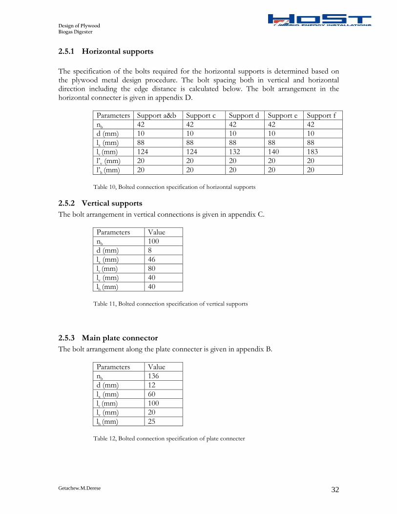
2.5.1 Horizontal supports
The specification of the bolts required for the horizontal supports is determined based on the plywood metal design procedure. The bolt spacing both in vertical and horizontal direction including the edge distance is calculated below. The bolt arrangement in the horizontal connecter is given in appendix D.
Parameters Support a&b Support c Support d Support e Support f
nb 42 42 42 42 42
d (mm) 10 10 10 10 10
lx (mm) 88 88 88 88 88
ly (mm) 124 124 132 140 183
l’v (mm) 20 20 20 20 20
l’h (mm) 20 20 20 20 20
Table 10, Bolted connection specification of horizontal supports
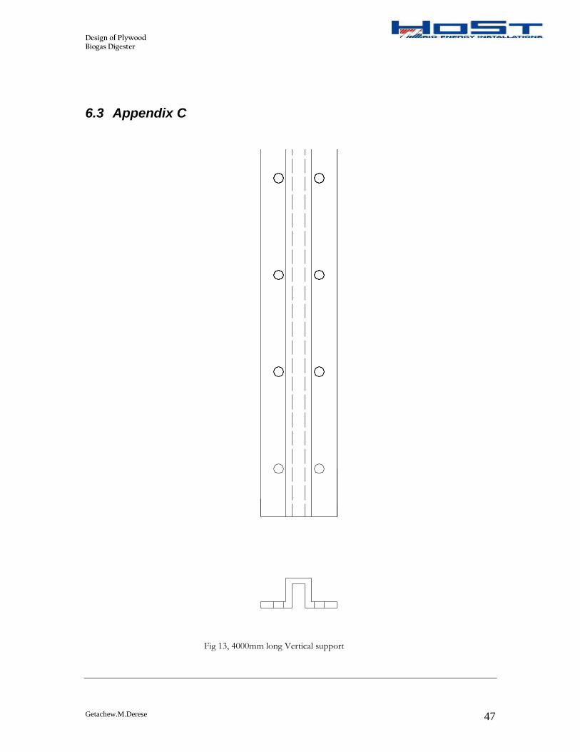
2.5.2 Vertical supports
The bolt arrangement in vertical connections is given in appendix C.
Parameters Value
nb 100
d (mm) 8
lx (mm) 46
ly (mm) 80
lv (mm) 40
lh (mm) 40
Table 11, Bolted connection specification of vertical supports
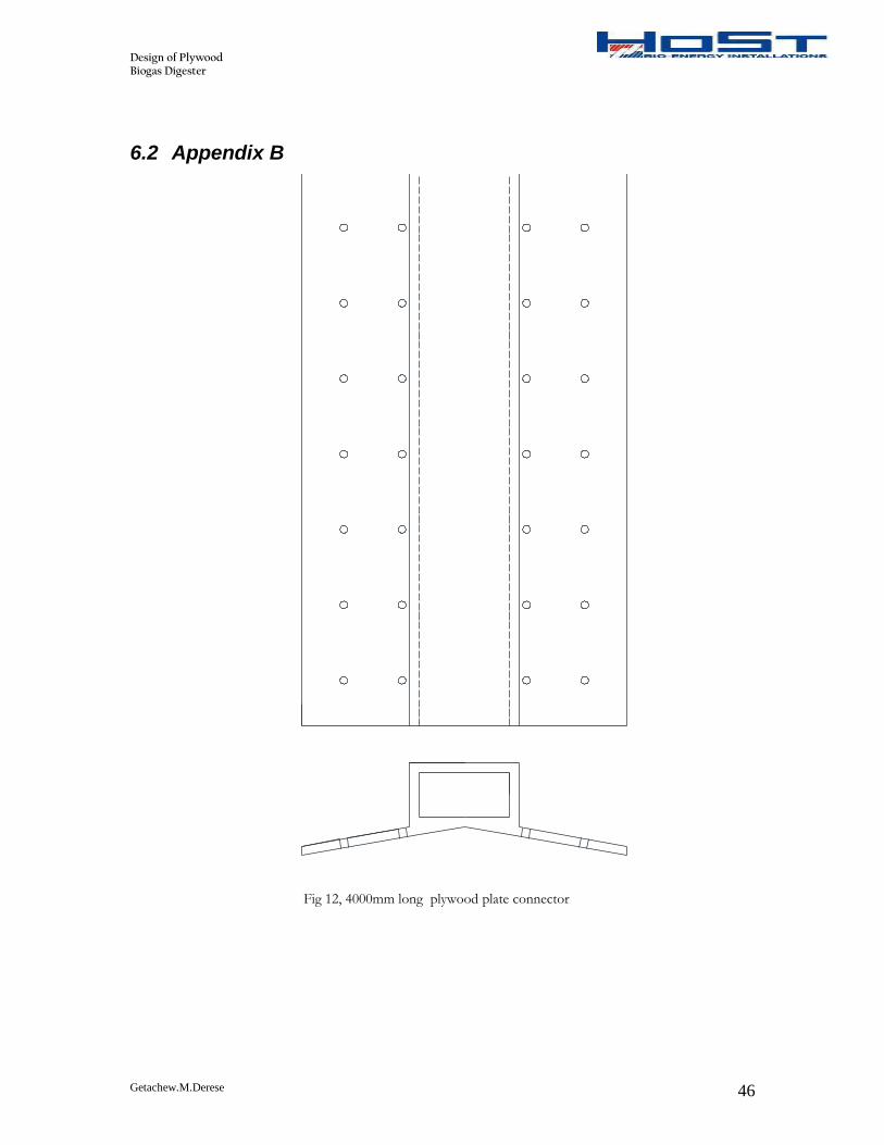
2.5.3 Main plate connector
The bolt arrangement along the plate connecter is given in appendix B.
Parameters Value
nb 136
d (mm) 12
lx (mm) 60
ly (mm) 100
lv (mm) 20
lh (mm) 25
Table 12, Bolted connection specification of plate connecter
Design of Plywood Biogas Digester
Getachew.M.Derese 33
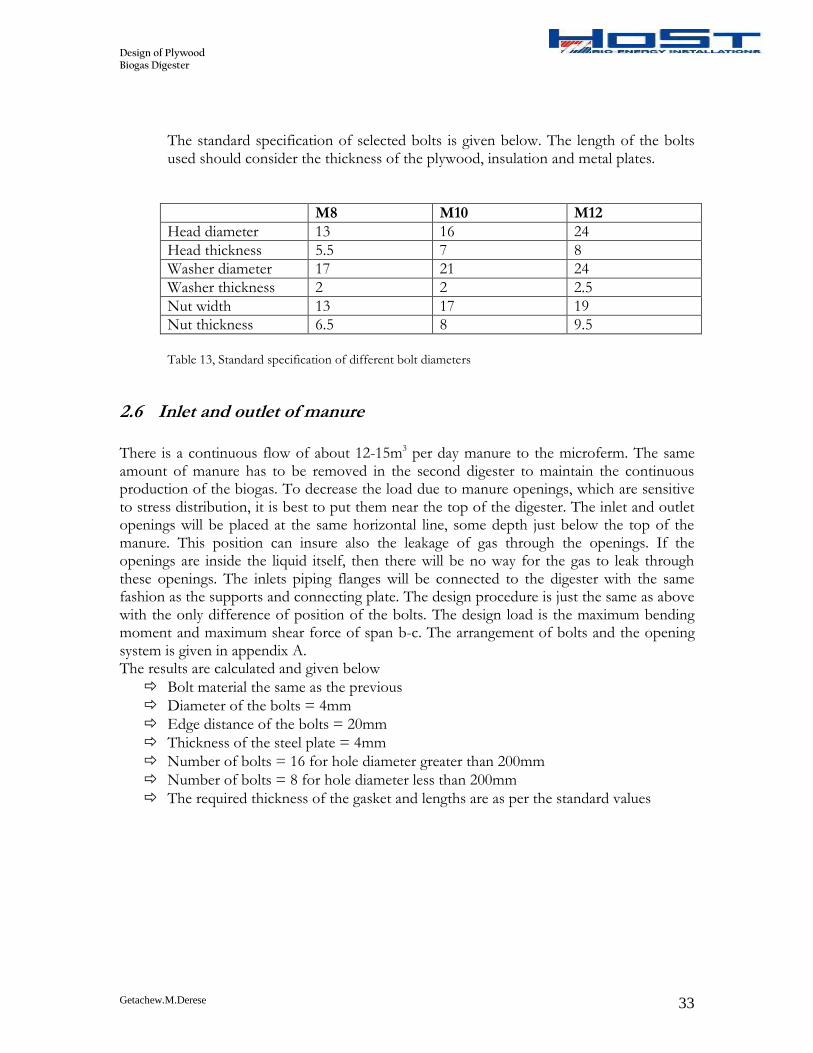
The standard specification of selected bolts is given below. The length of the bolts used should consider the thickness of the plywood, insulation and metal plates.
M8 M10 M12
Head diameter 13 16 24
Head thickness 5.5 7 8
Washer diameter 17 21 24
Washer thickness 2 2 2.5
Nut width 13 17 19
Nut thickness 6.5 8 9.5
Table 13, Standard specification of different bolt diameters
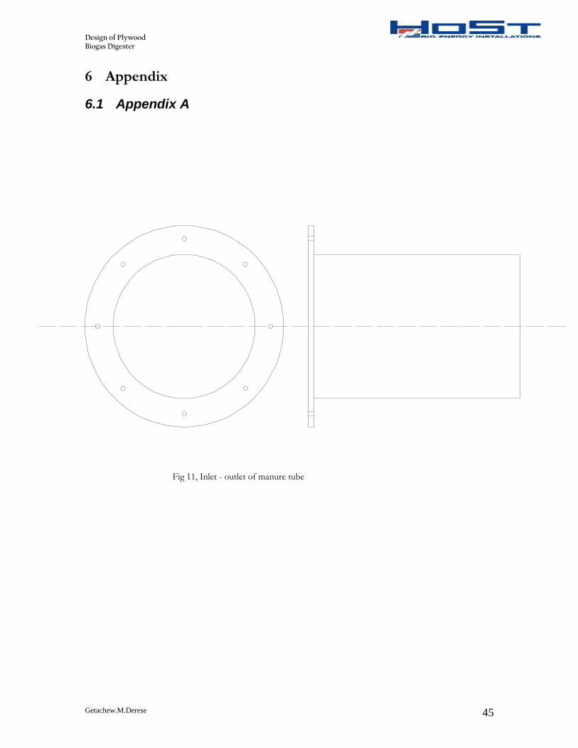
2.6 Inlet and outlet of manure
There is a continuous flow of about 12-15m3 per day manure to the microferm. The same amount of manure has to be removed in the second digester to maintain the continuous production of the biogas. To decrease the load due to manure openings, which are sensitive to stress distribution, it is best to put them near the top of the digester. The inlet and outlet openings will be placed at the same horizontal line, some depth just below the top of the manure. This position can insure also the leakage of gas through the openings. If the openings are inside the liquid itself, then there will be no way for the gas to leak through these openings. The inlets piping flanges will be connected to the digester with the same fashion as the supports and connecting plate. The design procedure is just the same as above with the only difference of position of the bolts. The design load is the maximum bending moment and maximum shear force of span b-c. The arrangement of bolts and the opening system is given in appendix A. The results are calculated and given below
Bolt material the same as the previous
Diameter of the bolts = 4mm
Edge distance of the bolts = 20mm
Thickness of the steel plate = 4mm
Number of bolts = 16 for hole diameter greater than 200mm
Number of bolts = 8 for hole diameter less than 200mm
The required thickness of the gasket and lengths are as per the standard values
Design of Plywood Biogas Digester
Getachew.M.Derese 34
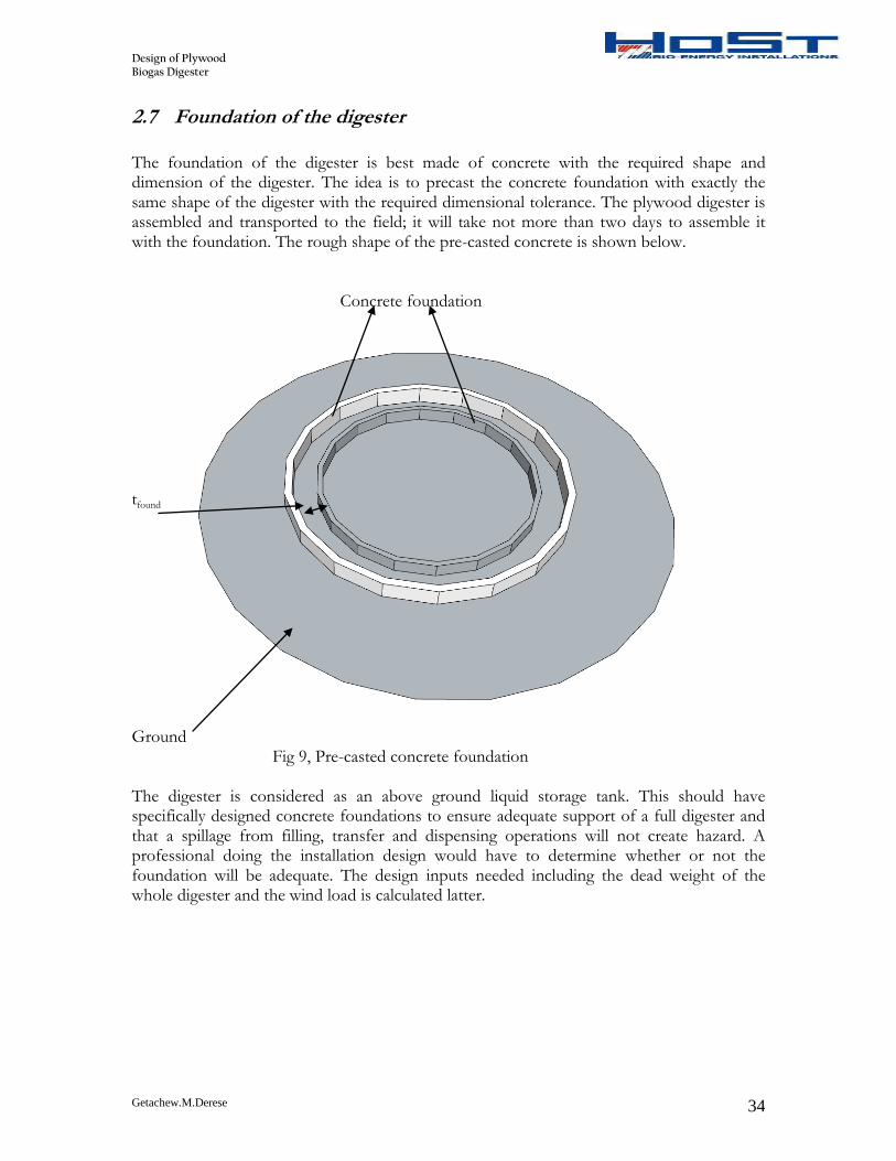
2.7 Foundation of the digester
The foundation of the digester is best made of concrete with the required shape and dimension of the digester. The idea is to precast the concrete foundation with exactly the same shape of the digester with the required dimensional tolerance. The plywood digester is assembled and transported to the field; it will take not more than two days to assemble it with the foundation. The rough shape of the pre-casted concrete is shown below. Concrete foundation tfound
Ground Fig 9, Pre-casted concrete foundation The digester is considered as an above ground liquid storage tank. This should have specifically designed concrete foundations to ensure adequate support of a full digester and that a spillage from filling, transfer and dispensing operations will not create hazard. A professional doing the installation design would have to determine whether or not the foundation will be adequate. The design inputs needed including the dead weight of the whole digester and the wind load is calculated latter.
Design of Plywood Biogas Digester
Getachew.M.Derese 35
2.8 Integrated double membrane biogas holder
The double membrane biogas holder consists of two layers, the inside layer and the outside layer. It can either be integrated with the digester top or can also be installed independently. The outer membrane maintains a consistent dome shape, while the inner membrane moves up or down depending up on gas storage requirements. Ambient air fans and valves add or release air from the space between the inner and outer membranes to maintain the consistent outer membrane shape and constant biogas pressure. The pressurized air has two functions; first it keeps the outer membrane in shape to withstand external wind and snow loads. Second it exerts constant pressure on the inner membrane and thus pushes gas at constant volume and pressure into the outlet pipe. Both membranes are clamped on top of the digester tank or anchored to the external wall of the tank. The supporting wire structure prevents the inner membrane from immersing into the substrate. The materials used for HoSt are EPDM rubber for the inside and fiber glass for the external cover.
2.8.1 Inside membrane supporter
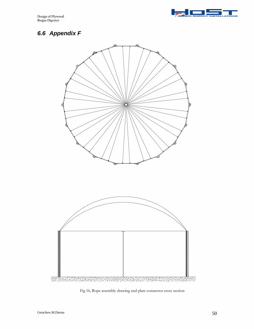
When there is no production of biogas or when all the produced biogas is utilized, the inside membrane will shrink and fall down. Unless a support is used for the inner membrane, it may make contact with the liquid and damaged. To protect this metal frames are used at the top of the digester. In this case a wire rope that runs from each vertical support to the central column at top of the digester is used. The arrangement of the ropes on each vertical support to the central column is shown in appendix F.
Design of Plywood Biogas Digester
Getachew.M.Derese 36
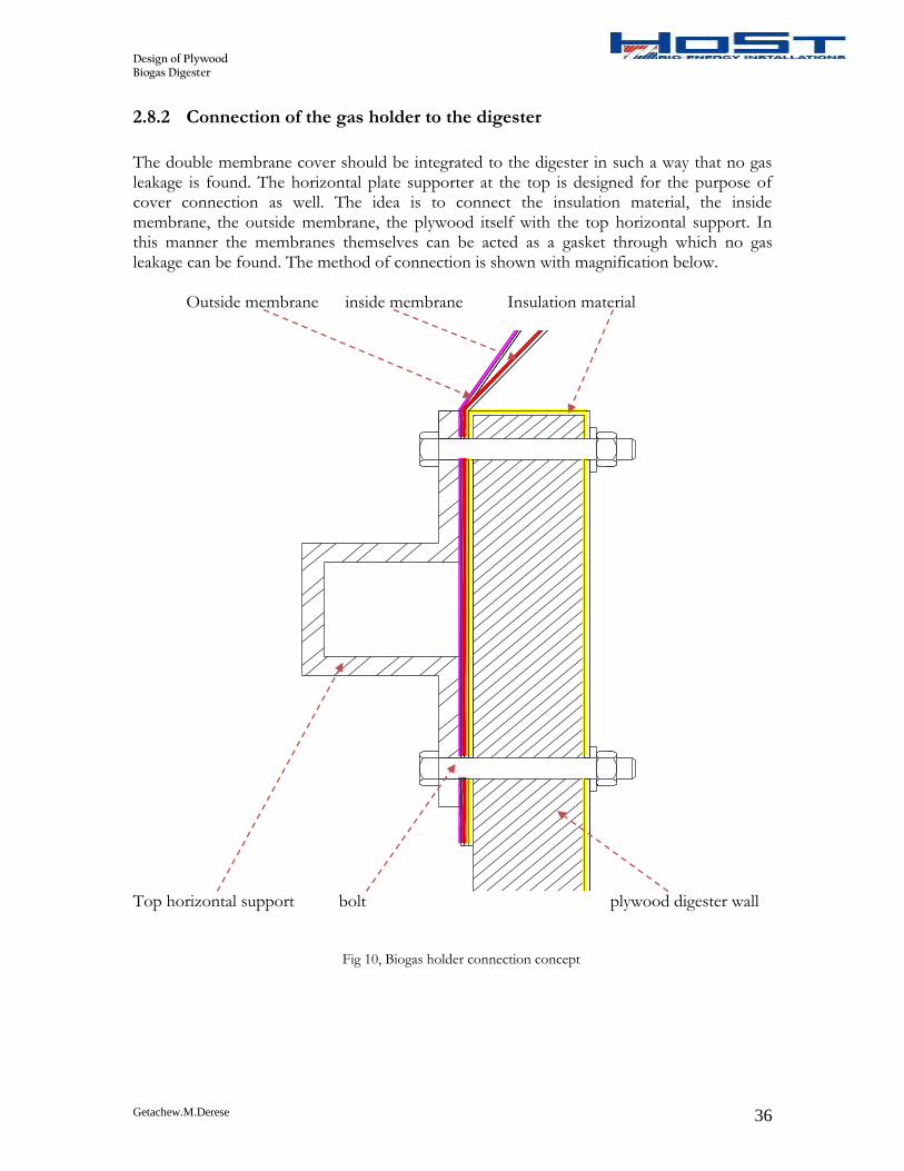
2.8.2 Connection of the gas holder to the digester
The double membrane cover should be integrated to the digester in such a way that no gas leakage is found. The horizontal plate supporter at the top is designed for the purpose of cover connection as well. The idea is to connect the insulation material, the inside membrane, the outside membrane, the plywood itself with the top horizontal support. In this manner the membranes themselves can be acted as a gasket through which no gas leakage can be found. The method of connection is shown with magnification below.
Outside membrane inside membrane Insulation material
Top horizontal support bolt plywood digester wall Fig 10, Biogas holder connection concept
Design of Plywood Biogas Digester
Getachew.M.Derese 37
2.9 Digester design check
The characteristic stresses of the birch plywood with a thickness of 35mm is
Mpachart 4.38//,
Mpaperchart 6.36,
The compression stresses along the direction of the spans and perpendicular to the spans is 26.6Mpa and 25.6Mpa respectively. The design capacities are determined by multiplying the characteristics strength with service factors, capacity factors and in service factors
19191 **** gkkchardes
chardes *456.0
The longitudinal and circumferential stresses due to the maximum pressure exerted on the bottom of the digester is given by
Mpat
DPel 5506.2
4
Mpat
DPelt 1012.5
22
2.9.1 Dead weight of the digester
a) Weight of plywood and accessories
The weight of the plywood itself including the weights of the openings, manholes, bolts, external fittings, ladders, platforms, piping’s, etc.. is given by:
tgDHcW ogply ******
Where Cg is the factor to account the accessories which is 1.15 for this case. Substituting the other already known parameters the weight of the plywood is
NWply 32730
b) Weight of metal supports and connectors
The weight of the connecting metals is found by multiplying the volume of the plates by the density of steel (7850kg/m3) and the gravitational acceleration
steeliipi glAW
For the main connector and the vertical supports the length is the height of the digester and for the horizontal connectors the length is the width of the plywood plates; the result is found below;
Design of Plywood Biogas Digester
Getachew.M.Derese 38
Component Weight (N)
Connector 36373
Vertical support 6099
Horizontal support C 4366.4
Horizontal support D 6861.45
Horizontal support E 9356.53
Horizontal support F 9730.8 Table 14, Dead weight of metal connecters
c) Weight of insulation The insulation material is EPDM rubber which has a thickness of 1.5mm. One square meter of this material has one kilogram mass. Since the insulation will cover all the inside parts of the digester, the volume of the EPDM is found the same as the cylindrical plate: The value is found to be 346.16N which is relatively small because of the lower density and small thickness of the insulation required.
d) Weight of inside cover, outside cover and snow loading The minimum volume of biogas holder required is 100m3 so the height of the double membrane cover should be determined to handle this required volume. The double membrane cover has its own design with a maximum working pressure and expansion. But for this case a cover height of 3m is used at least fulfills the volume requirement. The volume of the cover with a height of 3m is given by;
2236
hrhV
If we substitute a height of 3m the volume is 141.5m3 which satisfies the requirement. Then the weight of the cover is calculated based on the volume of 3m height. Even if the double membrane cove which is best suited for snow loading is used in the biogas holder, there may be situations where the cover will be completely covered by snow. This may not be the situation, but the digester is checked for withstanding a snow thickness of maximum 20cm which covers all part of the membrane cover. The density of the snow is used to be 240kg/m3
The inside membrane material is EPDM rubber with a thickness of 1.5 mm and that of the outside membrane is fiber glass with a thickness of 1mm and a weight per unit area of 1.2kg/m2
Component Weight (N)
Inside membrane 124.98
Outside membrane 55.55
Snow cover 2265 Table 15, Dead weight of gas holder
The total dead weight of the digester is then the sum of all the weights calculated before which is equal to
NWdt 6.108307
The stress due to the dead weight of the digester which has a compressive effect is given by:
Design of Plywood Biogas Digester
Getachew.M.Derese 39
MPa
tDt
Wdtdw 0944.0
2.9.2 Wind loading
The load imposed on any structure by the action of the wind will depend on the shape of the structure and the wind velocity,
25.0 wadw uCP
Where dC is the drag coefficient and a Is the density of air
If we consider a maximum wind speed at the worst condition is 35m/s, the dynamic wind pressure for the vertical digester is approximated as:
)/(07.0 22 mNuP ww
Where uw is the wind speed in km/hr, substituting the values the maximum pressure exerted on the digester due to the wind speed is
22 /32.1111126*07.0 mNPw
Therefore the loading per linear meter of the digester is found by multiplying the exerted pressure by the mean diameter of the digester.
insplymean ttDD 22
Substituting the values mNPl /85.11638
The digester can be considered as a cantilever beam which is fixed at the ground and subjected to a uniformly distributed wind load. These, the maximum bending moment at the bottom of the digester is given by,
mkNhP
M lx .152.285
2
2
Where h is the height of the main digester plus the height of the cover. After knowing the maximum bending moment we can calculate now exerted pressure due to this wind loading,
t
D
I
M
v
xw
2
Iv is the second moment of area of the whole digester which is approximated as:
444 1356.164
mmEDDI ov
Mpaw 095.0
Design of Plywood Biogas Digester
Getachew.M.Derese 40
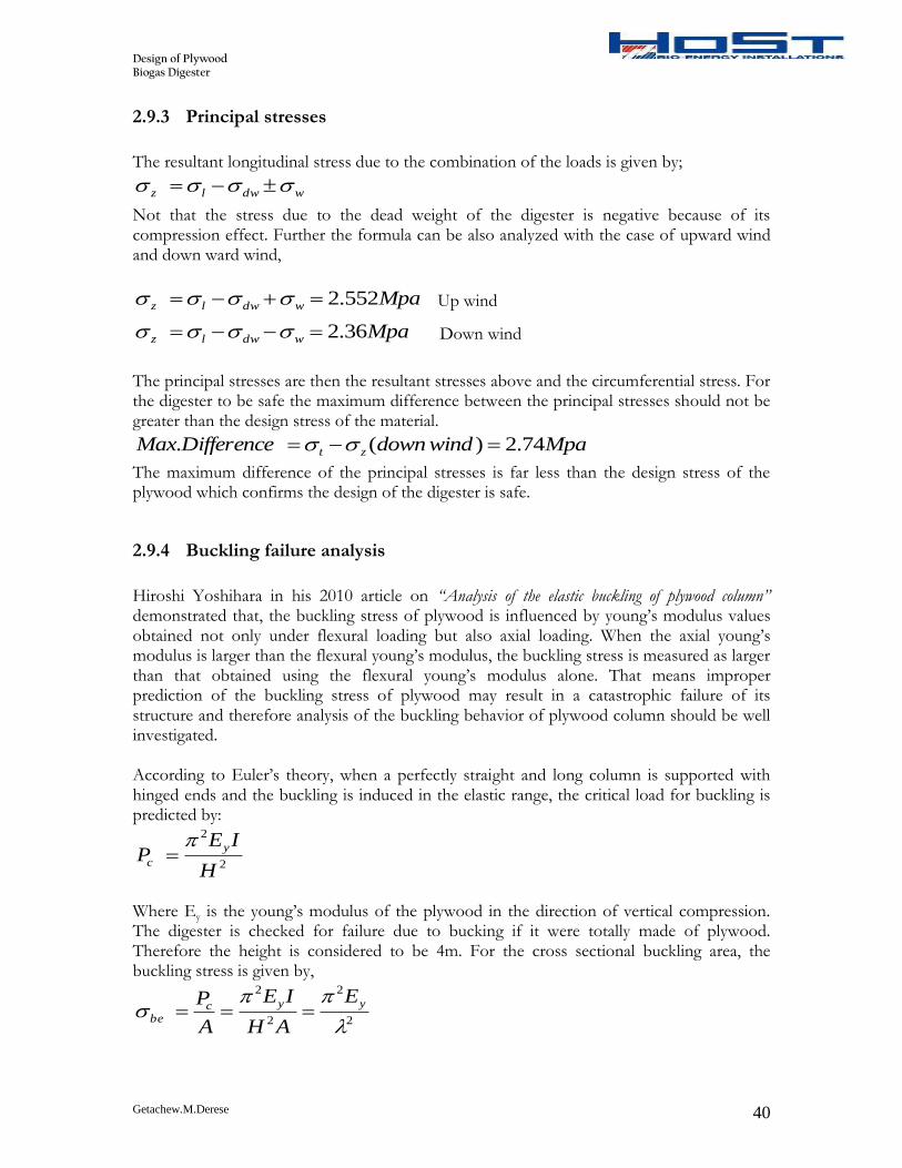
2.9.3 Principal stresses
The resultant longitudinal stress due to the combination of the loads is given by;
wdwlz
Not that the stress due to the dead weight of the digester is negative because of its compression effect. Further the formula can be also analyzed with the case of upward wind and down ward wind,
Mpawdwlz 552.2 Up wind
Mpawdwlz 36.2 Down wind
The principal stresses are then the resultant stresses above and the circumferential stress. For the digester to be safe the maximum difference between the principal stresses should not be greater than the design stress of the material.
MpawinddownDifferenceMax zt 74.2)(.
The maximum difference of the principal stresses is far less than the design stress of the plywood which confirms the design of the digester is safe.
2.9.4 Buckling failure analysis
Hiroshi Yoshihara in his 2010 article on “Analysis of the elastic buckling of plywood column” demonstrated that, the buckling stress of plywood is influenced by young’s modulus values obtained not only under flexural loading but also axial loading. When the axial young’s modulus is larger than the flexural young’s modulus, the buckling stress is measured as larger than that obtained using the flexural young’s modulus alone. That means improper prediction of the buckling stress of plywood may result in a catastrophic failure of its structure and therefore analysis of the buckling behavior of plywood column should be well investigated. According to Euler’s theory, when a perfectly straight and long column is supported with hinged ends and the buckling is induced in the elastic range, the critical load for buckling is predicted by:
2
2
H
IEP
y
c
Where Ey is the young’s modulus of the plywood in the direction of vertical compression. The digester is checked for failure due to bucking if it were totally made of plywood. Therefore the height is considered to be 4m. For the cross sectional buckling area, the buckling stress is given by,
2
2
2
2
yycbe
E
AH
IE
A
P
Design of Plywood Biogas Digester
Getachew.M.Derese 41
Where is the slenderness ration which is given by
AI
H
/
Hiroshi concluded in his experimental analysis that, for a plywood column with a slenderness ratio less than 100, the buckling stress of the plywood cannot be predicted by Euler equation. Instead if the ration is greater than 100, the buckling stress valued determined experimentally and those calculated with Euler formula show similarity. Therefore for the slenderness ratio of 100 and more, it is possible to use the Euler’s equation to analyze the buckling of plywood. For the selected birch plywood of 35mm thickness
H = 4000mm
Width = 1800mm
I = 3392mm4/mm width
A = 34.4mm2/mm width
Ey = 8547N/mm2 Therefore,
82.4024.34/3392
4000
The slenderness ratio is greater than 100, so we can fairly apply the Euler equation
MpaEy
be 52.082.402
8547*2
2
2
2
The buckling stress of 0.52Mpa implies that, the compression stress produced in the digester should not be greater than this value, if it is, then the digester will fail due to buckling. The maximum vertical compression stress in the digester will occur with worst combination of downward wind stress and stress due to the dead weight of the digester
wdwc max.
MpaMpaMpac 1894.0095.00944.0max.
It can be concluded that, even if the digester is considered to be none supported, it cannot fail due to buckling since 0.52Mpa > 0.1894Mpa. Therefore the digester is safe for failure due to buckling. The supported metals are also checked if they fail due to buckling, but because of the relatively short height of the digester and the greater modulus of elasticity of steel, it is safer.
Design of Plywood Biogas Digester
Getachew.M.Derese 42
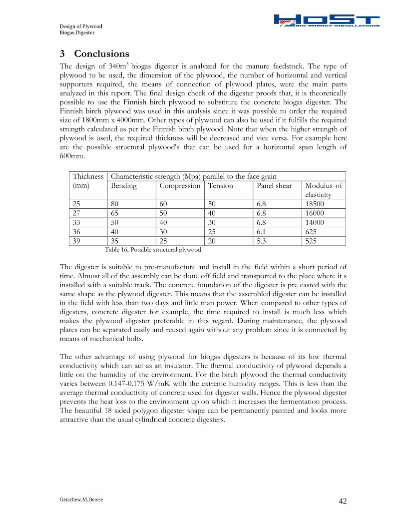
3 Conclusions The design of 340m3 biogas digester is analyzed for the manure feedstock. The type of plywood to be used, the dimension of the plywood, the number of horizontal and vertical supporters required, the means of connection of plywood plates, were the main parts analyzed in this report. The final design check of the digester proofs that, it is theoretically possible to use the Finnish birch plywood to substitute the concrete biogas digester. The Finnish birch plywood was used in this analysis since it was possible to order the required size of 1800mm x 4000mm. Other types of plywood can also be used if it fulfills the required strength calculated as per the Finnish birch plywood. Note that when the higher strength of plywood is used, the required thickness will be decreased and vice versa. For example here are the possible structural plywood's that can be used for a horizontal span length of 600mm.
Table 16, Possible structural plywood
The digester is suitable to pre-manufacture and install in the field within a short period of time. Almost all of the assembly can be done off field and transported to the place where it s installed with a suitable track. The concrete foundation of the digester is pre casted with the same shape as the plywood digester. This means that the assembled digester can be installed in the field with less than two days and little man power. When compared to other types of digesters, concrete digester for example, the time required to install is much less which makes the plywood digester preferable in this regard. During maintenance, the plywood plates can be separated easily and reused again without any problem since it is connected by means of mechanical bolts. The other advantage of using plywood for biogas digesters is because of its low thermal conductivity which can act as an insulator. The thermal conductivity of plywood depends a little on the humidity of the environment. For the birch plywood the thermal conductivity varies between 0.147-0.175 W/mK with the extreme humidity ranges. This is less than the average thermal conductivity of concrete used for digester walls. Hence the plywood digester prevents the heat loss to the environment up on which it increases the fermentation process. The beautiful 18 sided polygon digester shape can be permanently painted and looks more attractive than the usual cylindrical concrete digesters.
Thickness (mm)
Characteristic strength (Mpa) parallel to the face grain
Bending Compression Tension Panel shear Modulus of elasticity
25 80 60 50 6.8 18500
27 65 50 40 6.8 16000
33 50 40 30 6.8 14000
36 40 30 25 6.1 625
39 35 25 20 5.3 525
Design of Plywood Biogas Digester
Getachew.M.Derese 43
4 Recommendation and future work The difficult thing in engineering design is in the process of converting the theoretical work in to the actual practice. Here, to manufacture the plywood digester either in the prototype or final use, a series of manufacturing and assembling steps should be followed. Things to be done which are not covered in this report are the following:
Optimum manufacturing of the parts of the digester and assembly. The digester should be assembled in such a way that it minimizes man power and manufacturing cost.
Final leakage test of the digester after over all assembly has to be done to make sure that there is no leakage of fluid.
A detailed cost analysis of the plywood digester and comparison with the concrete digester should be done. The cost of different plywood's that could satisfy may give also a different result. Therefore the cost analysis should be done towards the optimum cost that could be achieved.
When a structural plywood other that a Finnish birch plywood is used, it will affect both the thickness of the plywood itself and the design of the bolted connections. So the corresponding modification has to be done based on the procedure that was done.
The strength of the metal frames used for the inside membrane protection (in this case the wire ropes) can be used from the previous experience, since it depends on the weight of the inside membrane.
The positions of the inlet and outlet openings can be changed to suitable position based on the previous experience. If man hole is required to the digester, the same procedure as the inlet and outlet openings could be done.
The requirement of the dimensional tolerances and allowances that should be made for the actual manufacturing has to be done to prevent overlapping of bolts for the vertical and horizontal supports and other requirements.
Design of Plywood Biogas Digester
Getachew.M.Derese 44
5 References 1. (n.d.). Retrieved from http://www.intplywood.nl/
2. (APA), T. E. (November 1997). Fastner Loads For Plywood - Bolts.
3. Association, A. F. (2007). Beam Formulas with Shear and Moment Diagrams.
Wachington DC: American Wood Council.
4. Australia, E. W. (July 2009). Structural Plywood and LVL Design Manual. Mick
McDowall.
5. CASE, J. (1999). Strength of Materials. London NWl 3BH: Arnold.
6. Donald E. Breyer, P. e. (2006). Design of wood structures. McGraw-Hill.
7. Foundation, F. F. (2002). Hand book of Finnish birch plywood. Lahti: Kirjapaino
Markprint Oy.
8. HEARN, E. J. (2000). Mechanics of Materials 1. United Kingdom: University of
Warwick.
9. Ian Smith, A. A. (2006). Design Method for Connections in Engineered.
Fredericton: University of New Brunswick, .
10. IIT, K. (2008). Structural Analysis.
11. Kermany, J. P. (2007). Structural Timber Design to Eurocode 5. Blackwell
Publisher.
12. M.Starczewaki. (1981). Non-Circular Pressure Vessels. British Engine Technical
Report.
13. Richardson's, C. &. (2003). CHEMICAL ENGINEERING Design. Britain.
14. Soltis, L. A. (1987). Bolted-Connection Design. United States Department of
Agriculture.
15. (May 2011). Steel Building Design:. UK EUROCODES.
16. Yoshihara, H. (2010). Analysis of the elastic buckling of a plywood column.
ELSEVIR Materials and Structures , 1075-1083.
Design of Plywood Biogas Digester
Getachew.M.Derese 45
6 Appendix
6.1 Appendix A
Fig 11, Inlet - outlet of manure tube
Design of Plywood Biogas Digester
Getachew.M.Derese 46
6.2 Appendix B
Fig 12, 4000mm long plywood plate connector
Design of Plywood Biogas Digester
Getachew.M.Derese 47
6.3 Appendix C Fig 13, 4000mm long Vertical support
Design of Plywood Biogas Digester
Getachew.M.Derese 48
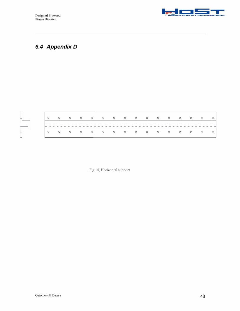
6.4 Appendix D
Fig 14, Horizontal support
Design of Plywood Biogas Digester
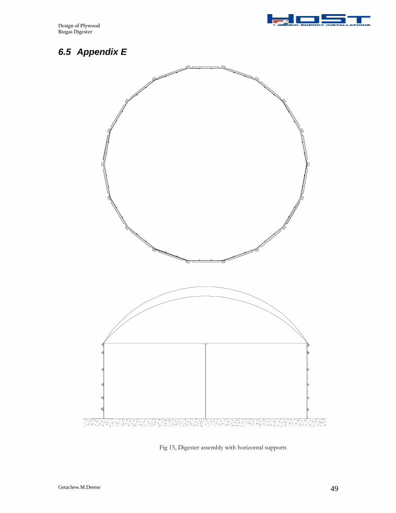
Getachew.M.Derese 49
6.5 Appendix E Fig 15, Digester assembly with horizontal supports
Design of Plywood Biogas Digester
Getachew.M.Derese 50
6.6 Appendix F Fig 16, Rope assembly drawing and plate connector cross section
Design of Plywood Biogas Digester
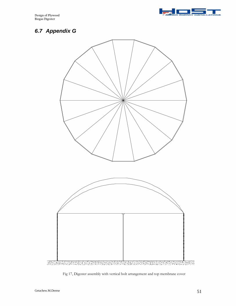
Getachew.M.Derese 51
6.7 Appendix G Fig 17, Digester assembly with vertical bolt arrangement and top membrane cover