16 Design of Robust Power System Stabilizer in an interconnected Power System with Wind Power Penetrations Cuk Supriyadi A.N 1 , I. Ngamroo 2 , Sarjiya 1 , Tumiran 1 and Y.Mitani 3 1 Department of Electrical Engineering, Gadjah Mada University, 2 the Center of Excellence for Innovative Energy Systems, King Mongkut's Institute of Technology Ladkrabang, Bangkok,10520, 3 the Graduate School of Engineering, Kyushu Institute of Technology, Fukuoka 804-8550, 1 Indonesia 2 Thailand 3 Japan 1. Introduction In the recent years, renewable electrical energy such as wind power generations, have achieved a significant level of penetration in the power systems due to infinite availability and low impact to environment. However, wind power generation is intermittent in nature. Matching the supply and the demand is often a problem. The power output fluctuations from wind power generations cause a problem of low frequency oscillation, deteriorate the system stability and make the power system operation more difficult. The power frequency and the tie-line power deviations persist for a long duration. In these situations, the governor system may no longer be able to absorb the frequency fluctuations due to its slow response (Elgerd & Fosha, 1970). To stabilize power oscillation, PSS is often used as an effective device to enhance the damping of electromechanical oscillations in power systems. The power system stabilizer is a supplementary control system, which is often applied as part of excitation control system. The basic function of the PSS is to apply a signal to the excitation system, creating electrical torques to the rotor, in phase with speed variation, that damp out power oscillations. In the past decades, the utilization of supplementary excitation control signals for improving the dynamic stability of power systems has received much attention. Extensive research has been conducted in many fields such as the effect of PSS on power system stability, PSS input signals, PSS optimum locations, and PSS tuning techniques. In (deMello & Concordia, 1969), the concept of synchronous machine stability as affected by excitation control has been examined. This work developed insights into effects of excitation systems and requirement of supplementary stabilizing action for such systems based on the concept of damping and synchronizing torques. These stabilizing requirements included the adjustment of voltage regulator gain parameters as well as the PSS parameters. Since the primary function of the PSS is to add damping to the power oscillations, basic control theories have been applied to select the most suitable input signal of PSS. Some readily available signals are generator rotor speed, calculated bus frequency, and electrical power. In www.intechopen.com
Transcript
16
Design of Robust Power System Stabilizer in an interconnected Power System with Wind Power
Penetrations
Cuk Supriyadi A.N1, I. Ngamroo2, Sarjiya1, Tumiran1 and Y.Mitani3 1Department of Electrical Engineering, Gadjah Mada University,
2the Center of Excellence for Innovative Energy Systems, King Mongkut's Institute of Technology Ladkrabang, Bangkok,10520,
3the Graduate School of Engineering, Kyushu Institute of Technology, Fukuoka 804-8550, 1Indonesia 2Thailand
3Japan
1. Introduction
In the recent years, renewable electrical energy such as wind power generations, have achieved a significant level of penetration in the power systems due to infinite availability and low impact to environment. However, wind power generation is intermittent in nature. Matching the supply and the demand is often a problem. The power output fluctuations from wind power generations cause a problem of low frequency oscillation, deteriorate the system stability and make the power system operation more difficult. The power frequency and the tie-line power deviations persist for a long duration. In these situations, the governor system may no longer be able to absorb the frequency fluctuations due to its slow response (Elgerd & Fosha, 1970). To stabilize power oscillation, PSS is often used as an effective device to enhance the damping of electromechanical oscillations in power systems. The power system stabilizer is a supplementary control system, which is often applied as part of excitation control system. The basic function of the PSS is to apply a signal to the excitation system, creating electrical torques to the rotor, in phase with speed variation, that damp out power oscillations. In the past decades, the utilization of supplementary excitation control signals for improving the dynamic stability of power systems has received much attention. Extensive research has been conducted in many fields such as the effect of PSS on power system stability, PSS input signals, PSS optimum locations, and PSS tuning techniques. In (deMello & Concordia, 1969), the concept of synchronous machine stability as affected by excitation control has been examined. This work developed insights into effects of excitation systems and requirement of supplementary stabilizing action for such systems based on the concept of damping and synchronizing torques. These stabilizing requirements included the adjustment of voltage regulator gain parameters as well as the PSS parameters. Since the primary function of the PSS is to add damping to the power oscillations, basic control theories have been applied to select the most suitable input signal of PSS. Some readily available signals are generator rotor speed, calculated bus frequency, and electrical power. In
www.intechopen.com
Wind Power
380
(Larsen & Swann, 1981), the application of PSS utilizing either of speed, frequency or power input signals has been presented. Guidelines were presented for tuning PSS that enable the user to achieve desired dynamic performance with limited effort. The need for torsional filters in the PSS path for speed input PSS was also discussed. The most PSS controls today use the generator rotor speed as the feedback input signal. They would provide robust damping over a wide range of operating conditions with minimum interaction (Murdoh et al, 2000). Simulation studies of PSS effects on inter-area and local modes of oscillations in interconnected power systems have been presented by (Klein et al, 1991) and (Klein et al, 1992). It was shown that the PSS location and the voltage characteristics of the system loads are significant factor in the ability of a PSS to increase the damping of inter-area oscillations. The procedures for the selection of the most effective machines for stabilization have been proposed. In (Abdalla et al, 1984), an eigenvalue-based measurement of relative improvement in the damping of oscillatory modes has been implemented and used as a criterion to find the best candidate machine for stabilizer application. On the other hand, an eigenvector analysis to identify the most effective generating units to be equipped with PSSs in multi-machine systems that exhibit dynamic instability and poor damping of several inter-area modes of oscillations, has been presented in (DeMello et al, 1980). Nowadays, the conventional lead/lag compensator PSS is widely used by the power system utility (Tse & Tso, 1993). Other types of PSS such as proportional-integral PSS (PI-PSS) and proportional-integral-derivative PSS (PID-PSS) have also been proposed by (Hsu & Hsu, 1986) and (Hsu & Liou, 1987). Several approaches based on modern control theories have been successfully applied to design PSSs. In (Yu & Siggers, 1971), the application of state-feedback optimal PSS has been presented, while an eigenvalue shifting technique for determining the weighing matrix in the performance index has been proposed by (Moussa & Yu, 1972). In (Fleming et al, 1981), a sequential eigenvalue assignment algorithm for selecting the parameters of stabilizers in a multi-machine power system has been presented. In sequential tuning, the stabilizer parameters are computed using repeated application of single-input/single-output (SISO) analysis. In (Zhou et al, 1992), the eigenvalue assignment has been proposed to design the optimal PSS. Besides, the new optimal linear quadratic regulator (LQR) based design has been presented by (Aldeen & Crusca, 1995). It is superior to previously reported LQR approaches. Moreover, PSS designs based on self tuning control (Cheng et al, 1986) and (Lim, 1989), fuzzy-logic system (Hsu & Cheng, 1990) and (Hoang & Tomsovic, 1996), artificial neural network (ANN) (Zhang et al, 1993), (Segal et al, 2000) and (Abido & Abdel_Magid, 1998) have been presented. However, since these techniques do not take the presence of system uncertainties such as system nonlinear characteristics, variations of system configuration due to unpredictable disturbances, loading conditions etc. into consideration in the system modeling, the robustness of these PSSs against uncertainties cannot be guaranteed.
To overcome these problems, H∞ control has been applied to design of robust PSS
configuration by (Chen & Malik, 1995) and (Yan, 1997). In these works, the designed H∞ PSS via mixed sensitivity approach have confirmed the significant performance and high robustness. In this approach, however, due to the trade-off relation between sensitivity
function and complementary sensitivity function, the weighting functions in H∞ control design
cannot be selected easily. Moreover, the order of H∞controller depends on that of the plant which is different from the conventional lead/lag PSS. Despite the significant potential of control techniques mentioned above, power system utilities still prefer the conventional lead/lag PSS structure. This is due to the ease of implementation, the long-term reliability, etc.
www.intechopen.com
Design of Robust Power System Stabilizer in an interconnected Power System with Wind Power Penetrations
381
On the other hand, much research on a conventional lead/lag PSS design has paid attentions to tuning of PSS parameters. The parameters of a lead/lag PSS are optimized under various operating conditions by heuristic methods such as tabu search (Abdel-Magid et al, 2001), genetic algorithm (Abdel-Magid et al, 1999), and simulated annealing (Abido, 2000). Using these approaches, the PSS parameters are obtained so that all of the electro-mechanical mode eigenvalues may be placed at the prescribed locations in the s-plane. In these designs, however, the uncertainty model is not embedded in the mathematical model of the power system. Furthermore, the robust stability against system uncertainties is not taken into consideration in the optimization process. Therefore, the robust stability margin of the system in these works may not be guaranteed in the face of several uncertainties. To solve this problem, the robust PSS design by a fixed structure with a conventional lead/lag PSS have been proposed [Cuk supriyadi et al, 2008]. In this work, the fixed structure robust
PSS design by the H∞ loop shaping technique is proposed. The normalized coprime factor is used to model system uncertainties. To optimize the control parameters, the performance and
robust stability conditions in the H∞ loop shaping technique are formulated as the objective function. As a result, the proposed PSSs are very robust against various uncertainties. With lower order, the stabilizing effect and robustness of the proposed PSS are almost the same as
those of the PSS with high-order designed by H∞ loop shaping technique. In this works, however, the weighting functions in H∞ control design cannot be selected easily. To tackle this problem, a new parameters optimization of robust PSS is proposed. The inverse additive perturbation is applied to represent unstructured system uncertainties. The configuration of PSS is a conventional second-order lead-lag compensator. To tune the PSS parameters, the concept of enhancement of system robust stability margin is formulated as the optimization problem. The genetic algorithm (GA) is applied to solve the problem and achieve the PSS parameters. Simulation studies in the two-area four-machine system with wind farms confirm that the damping effect and robustness of the proposed PSS are superior to those of the compared PSS.
2. System modelling
2.1 Power system model
A two-area four-machine interconnected power system with wind farms in Fig. 1 is used to design PSS. Each generator is represented by a 5th-state transient model. It is equipped with a simplified exciter and PSS with the speed deviation input. L1 and PW1 are load and wind farms in area 1, respectively. L2 and PW2 are load and wind farms in area 2, respectively.
Fig. 1. Two areas four machines power system with wind farms
www.intechopen.com
Wind Power
382
The linearized state equation of system in Fig. 1 can be expressed as
,pss iX A X B u•Δ = Δ + Δ (1)
,pss iY C X D uΔ = Δ + Δ (2)
, , ( )pss i pss i iu K s ωΔ = Δ (3)
Where the state vector ' 'T
d q fdX e e Eδ ω⎡ ⎤Δ = Δ Δ Δ Δ Δ⎣ ⎦ , the output vector [ ]Y ωΔ = Δ ,
,pss iuΔ is the control output signal of the PSS no. i ( , ( )pss iK s ), which uses only the angular
velocity deviation ( ωΔ ) as a feedback input signal and i is the number of PSS. Note that the
system in (1) is a Multi-input Multi-output (MIMO) system. The proposed method is
applied to design a robust PSS K(s). The system of (1) is referred to as the nominal plant G.
2.2 Wind power model 2.2.1 Wind velocity model
The output power of wind generator depends on wind velocity. The wind speed model
chosen in this study consists of four-component model (Dong-Jiang & Li Wang, 2008), and is
defined by
W WB WG WR WNV V V V V= + + + (4)
where:
WBV = Base wind velocity
WGV = Gust wind component
WRV = Ramp wind component
WNV = Noise wind component
The base wind velocity component is represented by
WB BV K= (5)
Where KB is a constant, this component is always assumed to be presented in a wind power. The gust wind velocity can be expressed by
1
cos 1 1
1
0
0
G
WG G G G
G G
t T
V V T t T T
t T T
<⎧⎪= < < +⎨⎪ > +⎩ (6)
where:
cosV = 1( / 2){1 cos2 [( / ) ( / )]}G G GMAXG t T T Tπ− −
MAXG = the gust peak TG = the gust period T1G = the gust starting time (1-cosine) gust is an essential component of wind velocity for dynamic studies.
www.intechopen.com
Design of Robust Power System Stabilizer in an interconnected Power System with Wind Power Penetrations
383
The ramp wind velocity component is described by
1
1 2
2
0
0
R
WR ramp R R
R
t T
V V T t T
t T
<⎧⎪= < <⎨⎪ >⎩ (7)
where:
rampV = 2 1 2[1 ( ) /( )]R R RMAXR t T T T− − −
MAXR = the ramp peak T1R = the ramp start time T2R = the ramp maximum time This component may be used to approximate a step change with T2R >T1R. The random noise component can be defined by
1/2
1
2 [ ( ) ] cos( ) 0N
WN V i i ii
V S t tω ω ω φ=
= Δ + <∑ (8)
where:
( 1 / 2)i iω ω= − Δ
iφ = a random variable with uniform probability density on the interval 0 to 2π
and the spectral density function is defined by
2
2 2 4/3
2 [ ]( )
[1 ( / ) ]i
N iV i
K FS
Fωωω π μπ= + (9)
Where KN (=0.004) is the surface drag coefficient, F(=2000) is turbulence scale, and μ is the mean speed of wind at reference height. Various study have shown that values of N=50, and Δω = 0.5-2.0 rad/s provide results of excellent accuracy.
2.2.2 Characteristic of wind generator output power
The output power of studied wind generator is expressed by a nonlinear function of the power coefficient Cp as function of blade pitch angle, ┚, and tip speed ratio, ┛. The tip speed ratio can be described by
blade Blade
W
R
V
ωλ = (10)
The power coefficient can be expressed by
( 3)
(0.44 0.0167 )sin 0.0184( 3)15 0.3
PCπ λβ λ ββ
⎡ ⎤−= − − −⎢ ⎥−⎣ ⎦ (11)
Finally, the output mechanical power of wind generator is
31
2W r P WP A C Vρ= (12)
where ρ (=1.25 kg/m3) is the air density and Ar(=1735 m2) is the swept area of blade.
www.intechopen.com
Wind Power
384
3. Proposed method
3.1 System uncertainties
System nonlinear characteristics, variations of system configuration due to unpredictable disturbances, loading conditions etc., cause various uncertainties in the power system. A controller which is designed without considering system uncertainties in the system modeling, the robustness of the controller against system uncertainties can not be guaranteed. As a result, the controller may fail to operate and lose stabilizing effect under various operating conditions. To enhance the robustness of power system damping controller against system uncertainties, the inverse additive perturbation (Gu et al, 2005) is applied to represent all possible unstructured system uncertainties. The concept of enhancement of robust stability margin is used to formulate the optimization problem of controller parameters.
G
AΔ
K
∑ ∑ Input Output
Controller
Nominal Plant
Additive Uncertainty
Fig. 2. Feedback system with inverse additive perturbation.
The feedback control system with inverse additive perturbation is shown in Fig.2. G is the nominal plant. K is the designed controller. For unstructured system uncertainties such as various generating and loading conditions, variation of system parameters and nonlinearities etc., they are represented by ΔA which is the additive uncertainty model. Based on the small gain theorem, for a stable additive uncertainty ΔA, the system is stable if
/(1 ) 1AG GK ∞Δ − < (13)
then,
1 / /(1 )A G GK∞ ∞Δ < − (14)
The right hand side of (14) implies the size of system uncertainties or the robust stability
margin against system uncertainties. By minimizing ( )1 ∞−G GK , the robust stability
margin of the closed-loop system is a maximum.
3.2 Implementation 3.2.1 Objective function
To optimize the stabilizer parameters, an inverse additive perturbation based-objective function is considered. The objective function is formulated to minimize the infinite norm of ( )1 ∞−G GK . Therefore, the robust stability margin of the closed-loop system will increase
www.intechopen.com
Design of Robust Power System Stabilizer in an interconnected Power System with Wind Power Penetrations
385
to achieve near optimum and the robust stability of the power system will be improved. As a result, the objective function can be defined as
Minimize ( )1 ∞−G GK (15)
It is clear that the objective function will identify the minimum value of ( )1 ∞−G GK for
nominal operating conditions considered in the design process.
3.2.2 Optimization problem
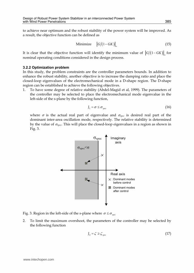
In this study, the problem constraints are the controller parameters bounds. In addition to enhance the robust stability, another objective is to increase the damping ratio and place the closed-loop eigenvalues of the electromechanical mode in a D-shape region. The D-shape region can be established to achieve the following objectives. 1. To have some degree of relative stability (Abdel-Magid et al, 1999). The parameters of
the controller may be selected to place the electromechanical mode eigenvalue in the left-side of the s-plane by the following function,
1 specJ σ σ= ≤ (16)
where σ is the actual real part of eigenvalue and σspec is desired real part of the dominant inter-area oscillation mode, respectively. The relative stability is determined
by the value of σspec. This will place the closed-loop eigenvalues in a region as shown in Fig. 3.
Imaginary
axis
Real axis
σspec
: Dominant modes
before control
: Dominant modes
after control
σspec<σ
Fig. 3. Region in the left-side of the s-plane where specσ σ≤
2. To limit the maximum overshoot, the parameters of the controller may be selected by the following function
2 specJ ζ ζ= ≥ (17)
www.intechopen.com
Wind Power
386
ζ and ζspec
are the actual and desired damping ratio of the dominant inter-area
oscillation mode, respectively. This will place the closed-loop eigenvalues in a wedge-
shape region in which as shown in Fig. 4.
ζspec
: Dominant modes before control
: Dominant modes
after control
Imaginary
axis
Real axis
ζspec>ζ
Fig. 4. Wedge-shape region in the s-plane where specζ ζ≥
Next, the conditions J1 and J2 are imposed simultaneously and will place the system closed-loop eigenvalues in the D-shape region characterized by specζ ζ≥ and
specσ σ≤ as shown in
Fig. 5. It is necessary to mention here that only the unstable or lightly damped electromechanical modes of oscillations are relocated.
ζspec Imaginary
axis
Real axisσspec
: Dominant modes before control
: Dominant modes
after control
σspec<σ
ζspec>ζ
Fig. 5. D-shape region in the s-plane where specσ σ≤ and specζ ζ≥
Therefore, the design problem can be formulated as the following optimization problem.
www.intechopen.com
Design of Robust Power System Stabilizer in an interconnected Power System with Wind Power Penetrations
387
Minimize ( )1 ∞−G GK (18)
Subject to ,spec specζ ζ σ σ≥ ≤ (19)
min maxK K K≤ ≤
min maxT T T≤ ≤
where ζ and spec
ζ are the actual and desired damping ratio of the dominant inter-area
oscillation mode, respectively; σ and spec
σ are the actual and desired real part, respectively;
maxK and minK are the maximum and minimum controller gains, respectively; maxT and
minT are the maximum and minimum time constants, respectively. This optimization
problem is solved by GA (GAOT, 2005) to search the controller parameters.
3.3 Parameters optimization by GA
In this section, GA is applied to search the controller parameters of PSS with off line tuning.
The flow chart of the proposed method is illustrated in Fig. 6. Each step is explained as
follows.
Is gen=max gen?
Start
Stop
Step 2. Initialize the parameters for GA
Gen=1
Step 5. Determine the best of current generation
Step 6. Gen=gen+1
Step 7. Genetic operator create the new population by selection, cross over and mutation.
Yes
No
Step 3. Randomly generate the initial solutions
Step 4. Evaluate Objective function
Step 1. Generate the objective function for GA
Fig. 6. Flow chart of the proposed design
www.intechopen.com
Wind Power
388
Step 1. Generate the objective function for GA optimization. In this study, the performance and robust stability conditions in inverse additive perturbation design approach is adopted to design a robust PSS. The conventional PSS with a 2nd-order lead-lag controller is represented by
where, ,pss iuΔ and iωΔ are the control output signal and the rotor speed deviation at the i-th
machine, respectively; iK is a controller gain; WT is a wash-out time constant (s): and
1,iT , 2 ,iT , 3,iT , and 4,iT are time constants (s). Step 2. Initialize the search parameters for GA. Define genetic parameters such as
population size, crossover, mutation rate, and maximum generation. Step 3. Randomly generate the initial solution. Step 4. Evaluate objective function of each individual in (18) and (19). Step 5. Select the best individual in the current generation. Check the maximum
generation. Step 6. Increase the generation. Step 7. While the current generation is less than the maximum generation, create new
population using genetic operators and go to step 4. If the current generation is the maximum generation, then stop.
4. Performance simulation and results
In the optimization, the ranges of search parameters and GA parameters are set as follows:
ζ and ζspec
are actual and desired damping ratio is set as 0.1, respectively, σ and σ spec are
actual and desired real part of the inter-area oscillation mode is set as -0.1, ,miniK and ,maxi
K
are minimum and maximum gains of PSS are set as 1 and 30, ,minjiT and ,maxjiT are minimum
and maximum time constants of PSS are set as 0.01 and 1. wT is set to 10 s. The optimization
problem is solved by genetic algorithm. Under the normal operating condition case 1 in
Table 1, the robust control parameters (RPSS) are obtained as follows.
1
0.8638 1 0.8538 125.05
0.7425 1 0.7227 1PSS
s sK
s s
+ +⎛ ⎞⎛ ⎞= ⎜ ⎟⎜ ⎟+ +⎝ ⎠⎝ ⎠
2
0.5395 1 0.5124 125.58
0.3324 1 0.3175 1PSS
s sK
s s
+ +⎛ ⎞⎛ ⎞= ⎜ ⎟⎜ ⎟+ +⎝ ⎠⎝ ⎠
3
0.4940 1 0.4748 112.79
0.2545 1 0.2675 1PSS
s sK
s s
+ +⎛ ⎞⎛ ⎞= ⎜ ⎟⎜ ⎟+ +⎝ ⎠⎝ ⎠ (21)
4
0.6235 1 0.6133 112.50
0.1806 1 0.1350 1PSS
s sK
s s
+ +⎛ ⎞⎛ ⎞= ⎜ ⎟⎜ ⎟+ +⎝ ⎠⎝ ⎠
Table 2 shows the eigenvalue and damping ratio of the dominant inter-area oscillation mode. Clearly, the damping ratio of the oscillation mode of RPSS is improved as designed in comparison with No PSS case.
www.intechopen.com
Design of Robust Power System Stabilizer in an interconnected Power System with Wind Power Penetrations
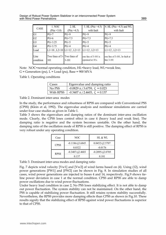
Note: NOC=normal operating condition, HL=heavy load, WL=weak line, G = Generation (pu), L = Load (pu), Base = 900 MVA
Table 1. Operating conditions
Cases Eigenvalue and damping ratio
No PSS -0.0829 ± j 3.6759, ζ = 0.023
With RPSS -0.3407 ± j 2.4603, ζ = 0.137
Table 2. Dominant inter-area modes
In the study, the performance and robustness of RPSS are compared with Conventional PSS (CPSS) (Klein et al, 1992). The eigenvalue analysis and nonlinear simulations are carried under four case studies as given in Table 1. Table 3 shows the eigenvalues and damping ratios of the dominant inter-area oscillation mode. Clearly, the CPSS loses control effect in case 4 (heavy load and weak line). The damping ratio is negative and the system becomes unstable. On the other hand, the damping ratio of the oscillation mode of RPSS is still positive. The damping effect of RPSS is very robust under any operating condition.
Case NOC HL & WL
-0.1186±j3.6845 0.0452±j2.5707
0.0322 -0.0176
-0.3407±j2.4603 -0.2095±j2.0705
0.137 0.101
CPSS
RPSS
Table 3. Dominant inter-area modes and damping ratio
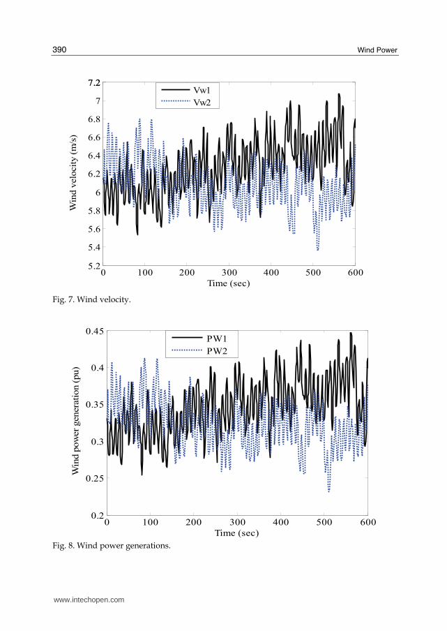
Fig. 7 depicts wind velocity [Vw1] and [Vw2] of wind farms based on (4). Using (12), wind power generations [PW1] and [PW2] can be shown in Fig. 8. In simulation studies of all cases, wind power generations are injected to buses 4 and 14, respectively. Fig.9 shows tie-line power deviation in case 1 at the normal condition. CPSS and RPSS are able to damp power oscillations due to wind power fluctuations. Under heavy load condition in case 2, No PSS loses stabilizing effect. It is not able to damp out power fluctuation. The system stability can not be maintained. On the other hand, the PSS is capable of stabilizing power fluctuation. It still retains system stability successfully. Nevertheless, the RPSS provides more damping effects than CPSS as shown in Fig.10. These results signify that the stabilizing effect of RPSS against wind power fluctuations is superior to that of CPSS.
www.intechopen.com
Wind Power
390
0 100 200 300 400 500 6005.2
5.4
5.6
5.8
6
6.2
6.4
6.6
6.8
7
7.27.2
Time (sec)
Win
d v
elo
cit
y (
m/s
)
Vw1
Vw2
Fig. 7. Wind velocity.
0 100 200 300 400 500 6000.2
0.25
0.3
0.35
0.4
0.45
Time (sec)
Win
d p
ow
er
genera
tion (
pu)
PW1
PW2
Fig. 8. Wind power generations.
www.intechopen.com
Design of Robust Power System Stabilizer in an interconnected Power System with Wind Power Penetrations
391
0 100 200 300 400 500 600-0.06
-0.05
-0.04
-0.03
-0.02
-0.01
0
0.01
0.02
0.03
0.04
0.05
0.06
0.07
Time (sec)
Tie
-lin
e p
ow
er
devia
tion (
pu)
CPSS
RPSS
Fig. 9. System responses in case 1 (normal condition).
0 100 200 300 400 500 600-0.06
-0.05
-0.04
-0.03
-0.02
-0.01
0
0.01
0.02
0.03
0.04
0.05
0.06
0.07
Time (sec)
Tie
lin
e p
ow
er
devia
tion (
pu)
NoPSS
CPSS
RPSS
Unstable
Fig. 10. System responses in case 2 (heavy load).
www.intechopen.com
Wind Power
392
0 5 10 15 20 25 30 35 40 45 50-0.4
-0.3
-0.2
-0.1
0
0.1
0.2
0.3
0.4
Time (sec)
Tie
lin
e p
ow
er devia
tion(p
u)
CPSS
RPSS
Fig. 11. System responses in case 3 (heavy load).
In case 3, it is assumed that the tie-line power transfers from areas 1 to 2 via two lines of tie-line 3-101, then one line is suddenly opened at 10 s. Simulation result is depicted in Fig. 11. The CPSS is not capable of damping power oscillation and eventually loses stabilizing effect. On the other hand, the RPSS is very robust against this situation. The power oscillation can be stabilized effectively.
0 10 20 30 40 50-5
-4
-3
-2
-1
0
1
Time (sec)
Tie
lin
e p
ow
er devia
tion (pu)
CPSS
RPSS
Fig. 12. System responses in case 4 (heavy load & weak line).
Finally, in case 4, it is assumed that one line of 3-101 is in service. A 3ø fault occurs at line 3-101 at 5s and the fault is cleared after 150 ms. Simulation results in Fig. 12 show that CPSS completely loses its control effect. On the other hand, the RPSS still retains system stability successfully. This explicitly shows the superior robustness of RPSS beyond CPSS.
www.intechopen.com
Design of Robust Power System Stabilizer in an interconnected Power System with Wind Power Penetrations
393
7. Conclusion
Robust PSS design based on inverse additive perturbation in a power system with wind farms has been proposed in this work. The parameters optimization of PSS is formulated based on an enhancement of system robust stability margin. Solving the problem by GA, PSS parameters are automatically obtained. The designed PSS is based on the conventional 2nd-order lead-lag compensator. Accordingly, it is easy to implement in real systems. The damping effects and robustness of the proposed PSS have been evaluated in the two areas four machines power system with wind farms. Simulation results confirm that the robustness of the proposed PSS is much superior to that of the CPSS against various uncertainties.
8. References
Elgerd O.I. & Fosha C.E. (1970), Optimum Megawatt Frequency – control of Multi-area Electric Energy Systems, IEEE Transactions on Power Systems, Vol. 89, pp. 556–63.
deMello F. & Concordia C. (1969), Concepts of Synchronous Machine Stability as Affected by Excitation Control, IEEE Transactions on Power Apparatus and Systems, Vol. 88, pp. 316-329.
Larsen E.V. & Swann D.A. (1981), Applying Power System Stabilizers. Part I: General Concepts; Part II: Performance Objectives and Tuning Concepts; Part III: Practical Considerations, IEEE Transactions on Power Apparatus and Systems, Vol. 100, pp. 3017-3046.
Murdoh A.; Sanderson H.C. & Lawson R. (2000), Excitation System Performance Specification to Meet Interconnection Requirements, Panel Session for the 2000 IEEE Power and Energy System Winter Meeting, Singapore, Vol. 1, pp.597- 602.
Klein M.; Rogers G.J. & Kundur P. (1991), A Fundamental Study of Inter-area Oscillations in Power Systems, IEEE Transactions on Power Systems, Vol. 6, No. 3, pp. 914-921.
Klein M.; Rogers G.J.; Moorty S. & Kundur P. (1992), Analytical Investigation of Factors Influencing Power System Stabilizers Performance, IEEE Transactions on Energy Conversion, Vol. 7, No. 3, pp. 382-390.
Abdalla O.H.; Hassan S.A. & Tweig N.T. (1984), Co-ordinated Stabilization of a Multi-machine Power System, IEEE Transactions on Power Apparatus and Systems, Vol. 103, pp.483-494.
DeMello F.P.; Nolan P.J.; Laskowski T.F. & Undrill J.M. (1980), Co-ordinated Application of Stabilizers in Multi-machine Power Systems, IEEE Transactions on Power Apparatus and Systems, Vol. 99, pp. 892-901.
Tse G.T. & Tso S.K. (1993), Refinement of Conventional PSS Design in Multimachine System by Modal Analysis, IEEE Transactions on Power Systems, Vol. 8, No. 2, pp. 598-605.
Hsu Y.Y. & Hsu C.Y. (1986), Design of a Proportional-Integral Power System Stabilizer, IEEE Transactions on Power Systems, Vol. 1, No. 2, pp. 46-53.
Hsu Y.Y. & Liou K.L. (1987), Design of Self-Tuning PID Power System Stabilizers for Synchronous Generators, IEEE Transactions on Energy Conversion, Vol. 2, No. 3, pp. 343-348.
Yu Y.N & Siggers C. (1971), Stabilization and Optimal Control Signals for a Power System, IEEE Transactions on Power Apparatus and Systems, Vol.90, pp. 1469-1481.
Moussa H.A.M. & Yu Y.N. (1972), Optimal Power System Stabilization through Excitation and/or Governor Control, IEEE Transactions on Power Apparatus and Systems, Vol.91, pp.1166-1174.
www.intechopen.com
Wind Power
394
Fleming R.J.; Mohan M.A. & Parvatisam K. (1981), Selection of Parameters of Stabilizers in Multi-machine Power Systems, IEEE Transactions on Power Apparatus and Systems, Vol.100, pp. 2329-2333.
Zhou E.Z.; Malik O.P. & Hope G.S. (1992), Design of Stabilisers for a Multimachine Power System Based on the Sensitivity of PSS Effect, IEEE Transaction on Energy Conversion, Vol. 7, pp.606-613.
Aldeen M. & Crusca F. (1995), Multimachine Power System Stabilisers Design Based on New LQR Approach, Proceeding of IEE Proceeding Generation Transmission and Distribution, Vol. 142, pp. 494-502.
Cheng S.J.; Chow Y.S.; Malik O.P. & Hope G.S. (1986), An Adaptive Synchronous Machine Stabilizer, IEEE Transactions on Power Systems, Vol. 1, pp.101-109.
Lim C.M (1989), A Self-tuning Stabilizer for Excitation or Governor Control of Power Systems, IEEE Transactions on Energy Conversion, Vol. 4, pp. 152-159, June 1989.
Hsu Y.Y. & Cheng C.H. (1990), Design of Fuzzy Power System Stabilisers for Multimachine Power Systems, Proceeding of IEEE, Vol. 137, No. 3.
Hoang P. & Tomsovic K. (1996), Design and Analysis of an Adaptive Fuzzy Power System Stabilizer, IEEE Transactions on Energy Conversion, Vol. 11, pp. 455 – 461.
Zhang Y.; Chen G.P ; Malik O.P. & G.S. Hope (1993), An Artificial Neural Network Based Adaptive Power System Stabilizer, IEEE Transactions on Energy Conversion, Vol. 8, No.1.
Segal R,; Kothari M.L & Madnani S. (2000), Radial Basis Function (RBF) Network Adaptive Power System Stabilizer, IEEE Transactions on Power Systems, Vol. 15, pp. 722-727.
Abido M.A & Abdel-Magid Y.L (1998), A Hybrid Neuro-fuzzy Power System Stabilizer for Multimachine Power Systems, IEEE Transactions on Power Systems, Vol. 13, No. 4, November 1998.
Chen S. & Malik O.P (1995), H∞ Optimisation-based Power System Stabilizer Design, Proc. of IEE Generation Transmission and Distribution, Vol. 142, pp.179-184.
Yan T.C (1997), Applying Optimisation Method to Power System Stabiliser Design –Parts 1 & 2, Transactions on Electrical Power and Energy System, Vol. 19, pp. 29-43.
Abdel-Magid Y.L; Abido M.A & Mantawy A.H (2001), Robust Tuning of Power System Stabilizers in Multimachine Power Systems, IEEE Transactions on Power Systems, Vol. 15, pp.735-740.
Abdel-Magid Y.L; Abido, M.A; AI-Baiyat S. & Mantawy A.H (1999), Simultaneous Stabilization of Multimachine Power Systems via Genetic Algorithm, IEEE Transactions on Power Systems, Vol. 14, No. 4, pp. 1428-1439.
Abido M.A (2000), Robust Design of Multi-machine Power System Stabilisers using Simulated Annealing, IEEE Transactions on Energy Conversion, Vol. 15, pp. 297-304.
Cuk Supriyadi A.N, Ngamroo I.; Kaitwanidvilai S.; Kunakorn A.; Hashiguchi T. & Goda T. (2008), Design of Robust Power System Stabilizer using Genetic Algorithm-based Fixed-Structure H∞ Loop Shaping Control, Proceeding of the 17th World Congress The International Federation of Automatic Control Seoul (IFAC), Korea, pp.11086- 11091.
Dong-Jiang & Li Wang (2008), Small-signal stability analysis of an autonomous hybrid renewable energy power generation/energy storage system part I : time-domain simulations, IEEE Transactions on Energy Conversion ,Vol. 23, No.1, pp. 311-320.
InTech ChinaUnit 405, Office Block, Hotel Equatorial Shanghai No.65, Yan An Road (West), Shanghai, 200040, China
Phone: +86-21-62489820 Fax: +86-21-62489821
This book is the result of inspirations and contributions from many researchers of different fields. A wide verityof research results are merged together to make this book useful for students and researchers who will takecontribution for further development of the existing technology. I hope you will enjoy the book, so that my effortto bringing it together for you will be successful. In my capacity, as the Editor of this book, I would like to thanksand appreciate the chapter authors, who ensured the quality of the material as well as submitting their bestworks. Most of the results presented in to the book have already been published on international journals andappreciated in many international conferences.
How to referenceIn order to correctly reference this scholarly work, feel free to copy and paste the following:
Cuk Supriyadi A.N, I. Ngamroo, Sarjiya, Tumiran and Y.Mitani (2010). Design of Robust Power SystemStabilizer in an Interconnected Power System with Wind Power Penetrations, Wind Power, S M Muyeen (Ed.),ISBN: 978-953-7619-81-7, InTech, Available from: http://www.intechopen.com/books/wind-power/design-of-robust-power-system-stabilizer-in-an-interconnected-power-system-with-wind-power-penetrati