Page 1
1
College of Engineering
Department of Mechanical Engineering
Spring 2018
Senior Design Project Report
Design of Solar Thermal Collector for The
Purpose of Optimizing Coil View Factor
In partial fulfillment of the requirements for the
Degree of Bachelor of Science in Mechanical Engineering
Group Number #4
Team Members
Student Name Student ID
1 201302587 Ibrahim Balhareth
2 201303522 Meshal Al Saiari
3 201301889 Omar Al Otaibi
4 201300164 Marwan Al Refaei
5 201200399 Mahmoud Khojandi
Project Advisors:
Advisor Name: Dr. Esam Jasim
Page 2
2
Abstract
A recent interest in renewable energy in Saudi Arabia has created a need to find
alternative suitable solutions for energy. Solar energy is one of the most interesting solutions
to produce renewable energy. Therefore, many research centers and universities have shown
interest in conducting experimental studies to improve and develop the efficiency of heat
transfer upon the existing system of solar thermal collector. The aim of this project is to
design and test a solar thermal collector. The collector will be used to test a number of
configurations for coils to maximize the heat transfer. The project results will provide
guidelines to utilize the most efficient coil geometry in solar thermal collectors.
Page 3
3
Acknowledgments To our Advisor, Dr. Esam Jasim and our instructor Dr. Nader Swalhi for the great
contribution in every step of our Senior Design Project which made this project interesting
and helpful for our future career and studies. Mechanical Engineering (ME) Department,
Prince Mohammad bin Fahd University as a whole, we thank you for your kind support and
assistance to us all through the college life.
Page 4
4
List of Figures
Figure1.1 Solar Thermal System ............................................................................................. 10
Figure 2.1 Schematic diagram of the system ........................................................................... 14
Figure 2.3 Results .................................................................................................................... 16
Figure 2.7 Solar Thermal Collector 5 ...................................................................................... 20
Figure 2.8 The dynamic simulation software tool IDA Indoor Climate and Energy 6 ........... 22
Figure 3.1System Components 7 ............................................................................................. 25
Figure 3.1 CAD System Design Model 8 .............................................................................. 29
Figure 3.3 The System After Assembly 9 ................................................................................ 31
Figure 4.1 Experimental Setup 10 ........................................................................................... 32
Figure 4.2 Sensors places 11 .................................................................................................... 33
Figure 4.3 Flow Meter Device 12 ............................................................................................ 34
Figure 4.4 Pressure Gauge 13 .................................................................................................. 35
Figure 4.5 Thermometer14 ...................................................................................................... 36
Figure 4.6 Light 15 .................................................................................................................. 37
Figure 4.7 Control Valve 16 .................................................................................................... 38
Figure 4.8 coils while the experimental 17 .............................................................................. 40
Figure 4.9 The Test Results 18 ................................................................................................ 42
Figure 4.10 schematic of three surfaces enclosure 18 ............................................................. 44
Figure 5.1 The Heat Source 19 ................................................................................................ 54
Figure 5.2 Thermal Collector Box 20 ...................................................................................... 55
Figure 5.4 Copper Coils After Pain Job21 ............................................................................... 56
Figure 5.5 Control Valve 22 ................................................................................................... 57
Page 5
5
List of Tables
Table1.1 Specifications of the box ........................................................................................... 11
Table 1.2 Specification of the coil pipes .................................................................................. 12
Table 1.3 Specification of the heater ....................................................................................... 12
Table 3.1 System Components Shapes 4 ................................................................................. 26
Table 3.2 Engineering Standards 5 .......................................................................................... 27
Table 3.2 Example of calculating the total heat transfer6 ....................................................... 28
Table 4.1 The water volume reading7 ..................................................................................... 41
Table 4.2 The Test Results 8.................................................................................................... 42
Table 4.3 Radiation Test Results 9 .......................................................................................... 45
Table 4.5 View Point Calculations 10 ..................................................................................... 46
Table 4.5 Net Heat Radiation Results 11 ................................................................................. 47
Table 5.1 Gantt Chart 12 .......................................................................................................... 49
Table 5.2 Team Members Task 13 .......................................................................................... 52
Table 5.3 Project Monitoring 14 .............................................................................................. 53
Table 5.3 Expenses of Material and Labor Work15 ................................................................ 58
Table B.1 Engineering Standards 16 ....................................................................................... 71
Page 6
6
Table of Content
Abstract ................................................................................................................................... 2
Acknowledgments...................................................................................................................... 3
List of Figures ............................................................................................................................ 4
List of Tables ............................................................................................................................. 5
Chapter 1: Introduction .......................................................................................................... 9
1.1 Project Definition .......................................................................................................... 9
1.2 Project Objectives ............................................................................................................. 9
1.3 Project Specifications ..................................................................................................... 10
1.4 Applications ................................................................................................................. 13
Chapter 2: Literature Review ............................................................................................... 14
2.1 Project background ...................................................................................................... 23
2.2 Previous Work ............................................................................................................. 23
2.3 Comparative Study ...................................................................................................... 24
Chapter 3: System Design ..................................................................................................... 25
3.1 Design Constraints and Design Methodology ................................................................... 25
3.1.1 Geometrical Constrains ......................................................................................... 25
3.1.2 Environmental ....................................................................................................... 26
3.1.3 Economic .................................................................................................................. 26
3.2 Engineering Design standards ........................................................................................ 26
3.3 Theory and Theoretical Calculations ........................................................................... 28
3.4 Product Subsystems and selection of Components ........................................................ 29
3.4.1 CAD Design of Product systems and Component ................................................... 29
3.5 Manufacturing and assembly (Implementation) .......................................................... 31
Chapter 4: System Testing and Analysis ............................................................................. 32
Page 7
7
4.1 Experimental Setup, Sensors and data acquisition system .......................................... 33
4.1.1 Inlet section .............................................................................................................. 33
4.1.2 The Radiation Collector Section .............................................................................. 37
4.1.3 Outlet section............................................................................................................ 37
4.2 Results, Analysis and Discussion ................................................................................ 39
4.2.1 Goals: ....................................................................................................................... 39
4.2.2 Experimental methodology ...................................................................................... 39
4.2.3 Errors and Challenges .............................................................................................. 39
4.2.4 Experimental procedure ........................................................................................... 40
4.2.5 Results and Discussions ........................................................................................... 41
Chapter 5: Project Management .......................................................................................... 44
5.1 Project Plan .................................................................................................................. 49
5.2 Contribution of Team Members .................................................................................. 52
5.3 Project Execution Monitoring ..................................................................................... 53
5.4 Challenges and Decision Making ................................................................................ 53
5.4.1 Project Set Up Failures ............................................................................................. 54
5.5 Project Bill of Materials and Budget ........................................................................... 58
Chapter 6: Project Analysis ................................................................................................. 59
6.1 Life-long Learning: ......................................................................................................... 59
6.1.1 Improve our Skills in Sensors Tools ........................................................................ 59
6.1.2 New Tools Helped With The Research .................................................................... 59
6.1.3 Project management skills ........................................................................................ 60
6.2 Impact of Engineering Solutions .................................................................................... 60
6.2.1 Economy ...................................................................................................................... 60
6.2.2 Society ......................................................................................................................... 61
Page 8
8
6.2.3 Enviorment .................................................................................................................. 61
6.3 Contemporary Issues Addressed .................................................................................... 61
Chapter 7: Conclusions and Future Recommendations..................................................... 62
7.1 Conclusions ................................................................................................................. 62
7.2 Future Recommendations ............................................................................................ 63
8. References ......................................................................................................................... 64
Appendix A: Progress Reports................................................................................................. 65
Appendix B: Engineering standards ........................................................................................ 71
Appendix C: CAD drawings and Bill of Materials .................................................................. 72
Page 9
9
Chapter 1: Introduction
1.1 Project Definition
This project is intended to design and manufacture the solar thermal collector that
used to demonstrate how solar energy or radiation energy could be converted into heat
energy. We will upgrade this system by puting different geometric of coil shapes painted by
black color inside the thermal collector one by one. The set-up for this system includes a
wooden box of the solar thermal collector, concave of aluminum sheets fixed inside the
wooden wall, different geometries of copper coils pipes, plastic hoses connected between
copper coil pipe and plastic pipes. In addition, we put measurements tools (flowumetric and
thermometer) for calculations. This system can illustrate how the water heater in a house
works or if used without water to illustrate how a radiator heats up a room.
1.2 Project Objectives
We have more than one objective in this project. First, designing a test rig coil in different
geometries and then designing a number of coil geometries. Furthermore, designing
experiments to study the best coil geometry efficiency in heat transfer.
Page 10
10
1.3 Project Specifications
There are three main parts in our projects which are pipe coils, absorber box, and heater.
As shown in Figure 1.1 there are four types pipe coils: (A) Conical coil, (B) Barrel coil, (C)
Hourglass coil, and (D) Constant pitch coil. Moreover, we have (E) Searchlight which is a
device that produces heat and radiation energy to (F) thermal collector box that covers by
aluminum sheets from inside to reflect the radiation to the pipe coil.
Figure1.1 Solar Thermal System
Page 11
11
1.3.2 Specifications of the box
The box is the solar thermal collector. Inside this box we will place the coil pipes.
Table 1.1, we listed the specification of box.
Table1.1 Specifications of the box
Specification Description
Material Of Front Side Glass
Material Of The Box Wood
Material Covered The Inside Area Of The Box Aluminum sheet
Wight 2 kg
Length 50mm
Width 50mm
Depth 50mm
Paint Black
Heat Absorber Area 1.5
Volume 125mm
Thickness Of Glass 1mm
Thickness Of Wood 20mm
Page 12
12
1.3.3 Specification of the coil pipes
The coil pipes are aimed to increase temperature of the inlet water. The coil pipes will
heat up the water and feed it to the tank. We manufactured 4 types of coil pipes. These coil
pipes have the same mass and volume, but they have various geometry. Table 1.2 indicates
the specification of coil pipes.
Table 1.2 Specification of the coil pipes
1.3.4 Specification of heat supply
Our heat supply is a light. It generates heat to heat up the coil pipes. Table 1.3 displays the
specification of heater.
Table 1.3 Specification of the heater
Specification Description
Power 1200 W
Length 482.6mm
Width From Head 292.1mm
Width From Bottom 304.8mm
Thickness From Head 88.9mm
Thickness From Bottom 114.3mm
Specification Description
Material Copper
Height 280 MM
Diameter 96 – 225 mm
Wight 5 kg
Paint Black
Thickness 1.2mm
Page 13
13
1.4 Applications
The main purpose is to use this system in residential buildings or industries where the
demand for hot water has a large impact on energy bills. Hence, this is a situation with a large
family which the hot water demand is excessive due to the frequent use of hot water along
with manufacturing companies.
Page 14
14
Chapter 2: Literature Review
The goal of this study is to understand the performance of integrated photovoltaic in
addition to the thermal solar system as a compared to a traditional solar water heater, which is
the old method to prove the idea of a photovoltaic and thermal solar system design. The
consumption of the commercial polycrystalline PV model is to make a PV/T. Additionally,
the usage of PV/T collector is to build an IPVTS. Recently all outcomes show that the solar
PV/T collector can get an excellent thermal efficiency. However, the study from the
economical side shows the idea of IPVTS is feasible too. It is concluded that the solar PV/T
collector created from a corrugated polycarbonate panel which can assure an excellent
thermal efficiency with very comparable temperature (within 4 C difference) between the PV
module and the water in the tank [1]. Figure 2.1 is the schematic diagram of the system.
Figure 2.1 Schematic diagram of the system
Page 15
15
The spiral coil is allowed to transfer of a considerable amount of heat at a low cost
and has a better rate of heat transfer capability. This study aims to examine the different
configurations applied in spiral heat exchangers configurations. The research correspondingly
explores the concept of transient behavior of spiral shaped tubes, witnessed upon embedment
of the coils in the rectangular conducting slab. Various configuration options are considered
to identify the most optimal configuration. The research seeks to demonstrate the
effectiveness of using large conductors as supplementary storage of heat. Both flowing water
and stagnant water are used in the system for different purposes. The container fluid is used
as storage whereas the copper made coils are used to carry the cold liquid. Measuring of the
water at different depths was used to ensure that the temperature distribution was uniform. It
was founded that the geometry of a coil number of loops and its orientation influences heat
transfer rate. It was concluded that the performance of vertically embedded coil was better
than the spiral coil embedded horizontally which is doubling of the loops enhanced the
performance of the coil. An experiment on the standard transfer of heat from a spiral coil was
carried out. The research documents how orientation, geometry, and the number of loops
affect a coil’s performance. The following summarizes the outcomes of the study. A
horizontally positioned coil was found out to be less efficient as compared to a vertically
positioned one. It was established that the rate of heat transfer increases along with the
number of loops. The research similarly indicates the accuracy of the results to be within the
margin of +-5%. Finally, It showed that the analysis based on the inclusion of coil curvature
does not reliably predict the impact of the orientation of a coil [2]. Figure 2.2 is the spiral
coil.
Figure 2.2 Spiral Coil
Page 16
16
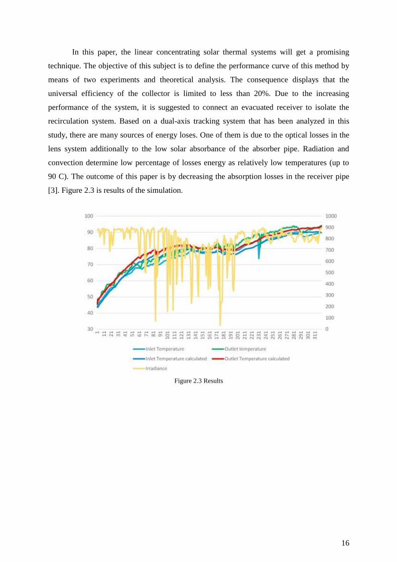
In this paper, the linear concentrating solar thermal systems will get a promising
technique. The objective of this subject is to define the performance curve of this method by
means of two experiments and theoretical analysis. The consequence displays that the
universal efficiency of the collector is limited to less than 20%. Due to the increasing
performance of the system, it is suggested to connect an evacuated receiver to isolate the
recirculation system. Based on a dual-axis tracking system that has been analyzed in this
study, there are many sources of energy loses. One of them is due to the optical losses in the
lens system additionally to the low solar absorbance of the absorber pipe. Radiation and
convection determine low percentage of losses energy as relatively low temperatures (up to
90 C). The outcome of this paper is by decreasing the absorption losses in the receiver pipe
[3]. Figure 2.3 is results of the simulation.
Figure 2.3 Results
Page 17
17
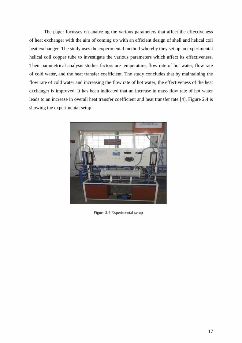
The paper focusses on analyzing the various parameters that affect the effectiveness
of heat exchanger with the aim of coming up with an efficient design of shell and helical coil
heat exchanger. The study uses the experimental method whereby they set up an experimental
helical coil copper tube to investigate the various parameters which affect its effectiveness.
Their parametrical analysis studies factors are temperature, flow rate of hot water, flow rate
of cold water, and the heat transfer coefficient. The study concludes that by maintaining the
flow rate of cold water and increasing the flow rate of hot water, the effectiveness of the heat
exchanger is improved. It has been indicated that an increase in mass flow rate of hot water
leads to an increase in overall heat transfer coefficient and heat transfer rate [4]. Figure 2.4 is
showing the experimental setup.
Figure 2.4 Experimental setup
Page 18
18
Concentrated solar thermal power or concentrating solar power is a perfect
technology, which interbreeds with different energy technologies for power generation.
Concentrated solar thermal can shares other technology with traditional power generation that
can be easily integrated with distinctive types of energy into a synergistic system. Hybridized
of concentrating solar power exists in different kinds accompanied by the levels of synergy.
This depends on the source of the hybrid energy, the concentrating solar power, and the
location of plant. There are numerous opportunities of fossil fuel with concentrated solar
thermal that inject solar heat at different temperatures [5].
Page 19
19
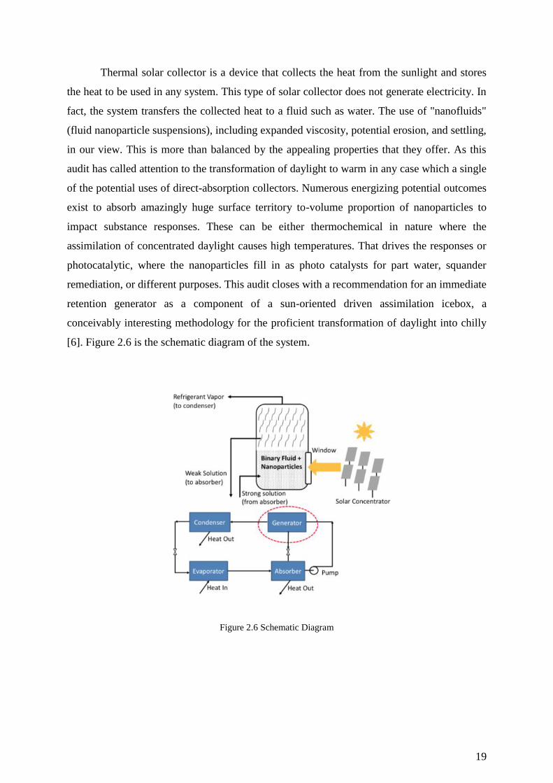
Thermal solar collector is a device that collects the heat from the sunlight and stores
the heat to be used in any system. This type of solar collector does not generate electricity. In
fact, the system transfers the collected heat to a fluid such as water. The use of "nanofluids"
(fluid nanoparticle suspensions), including expanded viscosity, potential erosion, and settling,
in our view. This is more than balanced by the appealing properties that they offer. As this
audit has called attention to the transformation of daylight to warm in any case which a single
of the potential uses of direct-absorption collectors. Numerous energizing potential outcomes
exist to absorb amazingly huge surface territory to-volume proportion of nanoparticles to
impact substance responses. These can be either thermochemical in nature where the
assimilation of concentrated daylight causes high temperatures. That drives the responses or
photocatalytic, where the nanoparticles fill in as photo catalysts for part water, squander
remediation, or different purposes. This audit closes with a recommendation for an immediate
retention generator as a component of a sun-oriented driven assimilation icebox, a
conceivably interesting methodology for the proficient transformation of daylight into chilly
[6]. Figure 2.6 is the schematic diagram of the system.
Figure 2.6 Schematic Diagram
Page 20
20
The solar thermal collector geometry and its design is a significant factor in solar –to-
thermal power conversion. In this research, stationary modern solar collector (helical solar
collector) was designed and examined. ASHRAE standards that have been utilized to this
collector to find out its performance. In fact, these experiments were conducted with water as
a working liquid in the open air of Ahwaz; this is city located at the south of Iran. The results
prove that the normal thermal efficiency for this collector is around 53%. However, that can
be utilized as an efficient new water heater. The tests demonstrate that the efficiency of the
helical solar water heater rises through the mass flow rate. Figure 2.7 is showing the solar
thermal collector [7].
Figure 2.7 Solar Thermal Collector 5
Page 21
21
As an effective, renewable, safe and eco-friendly energy resource, efficient utilization
of solar energy has been regarded undoubtedly as an encouraging solution to global energy
shortage and a mean to achieve sustainable development for human beings. Due to rapid
development of solar energy technologies, it decreased cost of solar energy equipment;
percentage of renewable energy by solar thermal and photovoltaic which are increasing as the
energy supply for buildings. The performance of solar collector highly relies on its tilt angel
with respect to horizontal plan and orientation (surface azimuth angle) of the collector. The
effective heat collection concept was proposed and optimized a model mathematically further
development to determine the optimum tilt angle and orientation for the solar collector. The
developed model has been applied in a case study of Lhasa district, in comparison with the
result obtained in accordance with conventional optimization results. The research result
showed that there is a out degree deviation etween the optimum results o tained
accordingly to effective heat collecting capacity and the optimum results acquired to
maximum total solar radiation falling on the solar collector [8].
Page 22
22
The paper aimed to analyze and simulate an integrated energy supply solution with
extended solar collectors and a combination unit and ground-source heat pump as illustrated
in figure 1. A parametric study was carried out that entailed optimizing certain variable such
as mass flow rate of collectors, orientation and tilt angle, collector heat loss, zone set point
temperature, effectiveness of heat exchanger and supply air flow rate. The study tested
different scenarios with different configuration to find the composition that would result in
the minimal electricity usage. The results of the study indicated that optimization of these
design and/or operating parameters led to a significant reduction in electricity use. This
optimization was done with the help of the dynamic simulation software tool IDA Indoor
Climate and Energy 4.6 as shown in figure 2.8. The study concluded that a larger solar
collector that is optimized in terms of orientation and tilt angle with a combination of a
ground-source heat pump would result in a higher reduction in energy utilized and higher
share of utilized renewable energy [9].
Figure 2.8 The dynamic simulation software tool IDA Indoor Climate and Energy 6
Page 23
23
2.1 Project background
Solar energy is a solution to produce renewable energy. Therefore, many research
centers and universities have shown interest in conducting experimental studies to improve
and develop the efficiency of heat transfer upon the existing system of the solar thermal
collector. The aim of this project is to design and test a solar thermal collector. The collector
will be used to test a number of configurations for coils to maximize the heat transfer. The
project results will provide guidelines to utilize the most efficient coil geometry in solar
thermal collectors. This project is about heat transfer and geometry is a big factor in the heat
transfer. In this study, we want to see the effect of heat transfer when changes happen to the
coil geometry. Our system components are a heater, solar thermal collector, 4 different
shapes of the copper coil, and water tank. The heater generates heat radiation that the solar
thermal collector absorbs the radiation heat. The copper coils will be placed inside the solar
thermal collector. The current study is to optimize the best copper coil geometry.
2.2 Previous Work
A heat exchanger can be defined as an engineering device that transfers heat from one
fluid (liquid or gaseous) stream to another. For this purpose, it usually employs parallel flow
or counter flow of the two fluids, constrained to their own series of pipes against each other.
The device is generally constructed in the form of one or more connected shells which
contain one of the fluids, and a bank of pipes within the shells that cover the other fluid. The
shell side is usually outfitted with baffles in order to increase heat transfer and suitably
modify pressure drop of the fluid [10]. Heat exchangers may be designed in a horizontal
configuration or a vertical one. The latter is especially useful for condensers, which use
isothermal flows in order to condense one of the fluids from a vapor to a liquid phase. The
experiments revealed that thermal transfer performance using spiral coils is influenced by
Reynolds number, fluid properties, coil orientation, and the curvature ratio of the spiral coils
(geometric angle). Increasing the number of loops is also shown to enhance the performance
of the spiral coil heat exchanger [10]. The experiment concluded that the geometrical
structure of the spiral coil heat exchanger and the increase in the number of loops per unit
length does affect the heat transfer performance. Moreover, the geometrical effect on the heat
transfer performance that was revealed by the experimental study shows that a heat transfer
geometrical factor exists.
Page 24
24
2.3 Comparative Study
Spiral coil heat exchangers play an essential function in cooling high concentration
and high viscous fluids. The experimental study was conducted to investigate the general heat
transfer effectiveness of water using the spiral coil heat exchanger with various geometrical
shapes. Heat exchangers are used extensively in process industries to extract or transfer heat
from or into one stream of fluid to another. They are designed in several configurations, two
of which are spiral and shell tube. The study compares five configurations involved in timed
heat transfer between a system of spiral pipes and a heat source in the form of a conducting
volume. An analysis also includes optimization of the coil configuration based on
effectiveness, efficiency, heat transfer, and the effects of different working fluids. The
experiments are performed on five spiral coils different in shape and identical length at the
transient and steady condition. The goal is to examine the impact of coil geometric shape on
the efficiency of heat transfer.
Page 25
25
Chapter 3: System Design
3.1 Design Constraints and Design Methodology
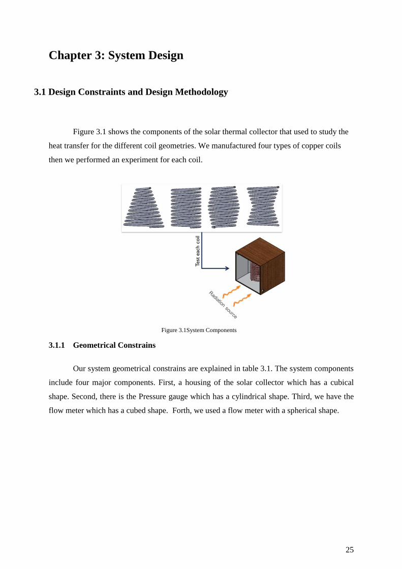
Figure 3.1 shows the components of the solar thermal collector that used to study the
heat transfer for the different coil geometries. We manufactured four types of copper coils
then we performed an experiment for each coil.
Figure 3.1System Components 7
3.1.1 Geometrical Constrains
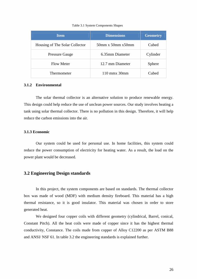
Our system geometrical constrains are explained in table 3.1. The system components
include four major components. First, a housing of the solar collector which has a cubical
shape. Second, there is the Pressure gauge which has a cylindrical shape. Third, we have the
flow meter which has a cubed shape. Forth, we used a flow meter with a spherical shape.
Page 26
26
Table 3.1 System Components Shapes 4
Item Dimensions Geometry
Housing of The Solar Collector 50mm x 50mm x50mm Cubed
Pressure Gauge 6.35mm Diameter Cylinder
Flow Meter 12.7 mm Diameter Sphere
Thermometer 110 mmx 30mm Cubed
3.1.2 Environmental
The solar thermal collector is an alternative solution to produce renewable energy.
This design could help reduce the use of unclean power sources. Our study involves heating a
tank using solar thermal collector. There is no pollution in this design. Therefore, it will help
reduce the carbon emissions into the air.
3.1.3 Economic
Our system could be used for personal use. In home facilities, this system could
reduce the power consumption of electricity for heating water. As a result, the load on the
power plant would be decreased.
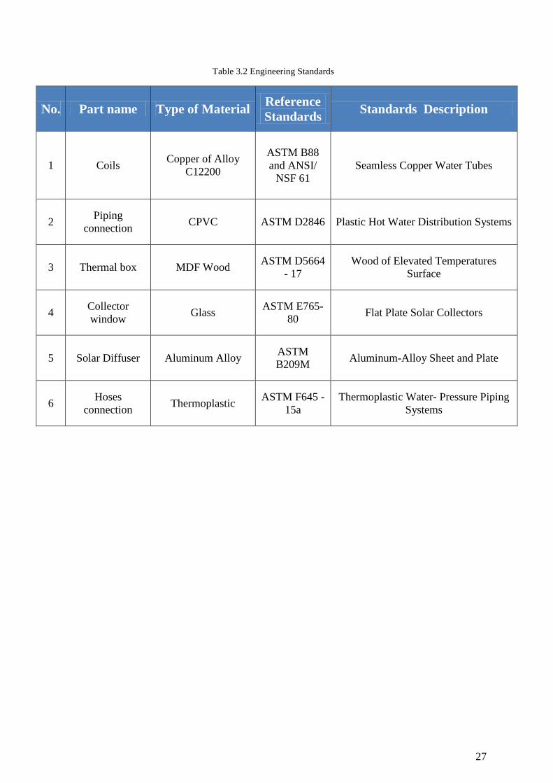
3.2 Engineering Design standards
In this project, the system components are based on standards. The thermal collector
box was made of wood (MDF) with medium density fireboard. This material has a high
thermal resistance, so it is good insulator. This material was chosen in order to store
generated heat.
We designed four copper coils with different geometry (cylindrical, Barrel, conical,
Constant Pitch). All the heat coils were made of copper since it has the highest thermal
conductivity, Constance. The coils made from copper of Alloy C12200 as per ASTM B88
and ANSI/ NSF 61. In table 3.2 the engineering standards is explained further.
Page 27
27
Table 3.2 Engineering Standards 5
No. Part name Type of Material Reference
Standards Standards Description
1 Coils Copper of Alloy
C12200
ASTM B88
and ANSI/
NSF 61
Seamless Copper Water Tubes
2 Piping
connection CPVC ASTM D2846 Plastic Hot Water Distribution Systems
3 Thermal box MDF Wood ASTM D5664
- 17
Wood of Elevated Temperatures
Surface
4 Collector
window Glass
ASTM E765-
80 Flat Plate Solar Collectors
5 Solar Diffuser Aluminum Alloy ASTM
B209M Aluminum-Alloy Sheet and Plate
6 Hoses
connection Thermoplastic
ASTM F645 -
15a
Thermoplastic Water- Pressure Piping
Systems
Page 28
28
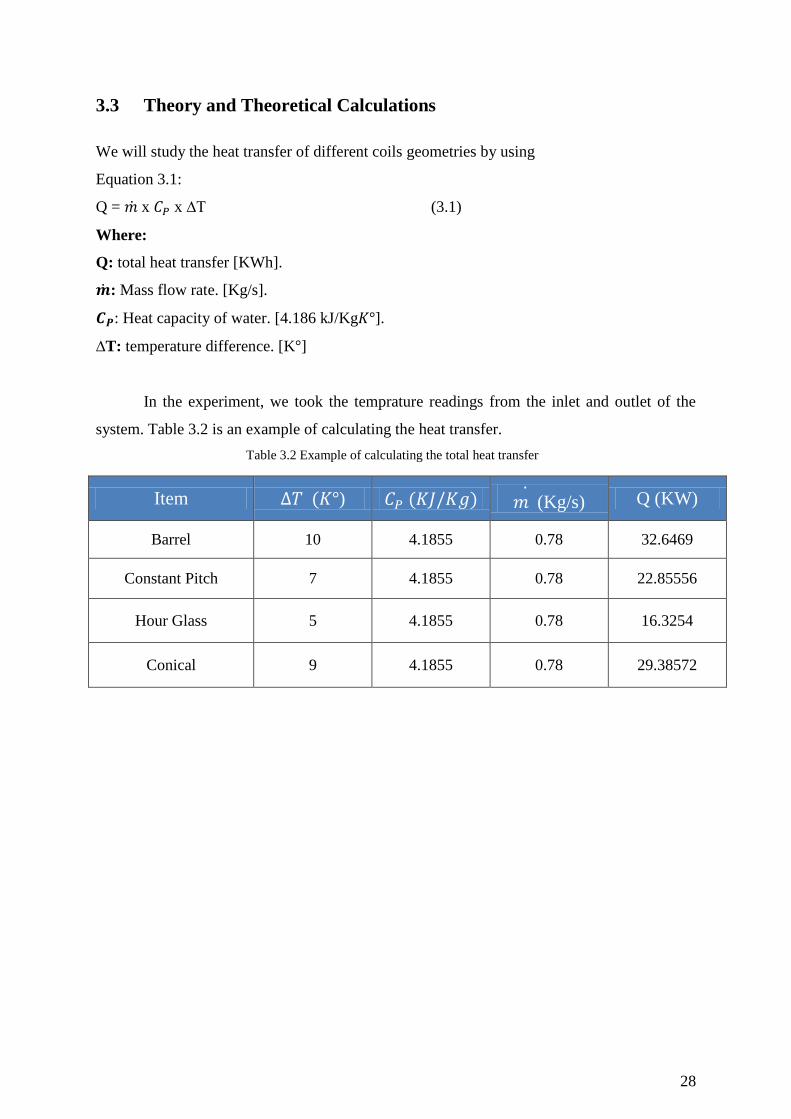
3.3 Theory and Theoretical Calculations
We will study the heat transfer of different coils geometries by using
Equation 3.1:
Q = x x ∆T (3.1)
Where:
Q: total heat transfer [KWh].
: Mass flow rate. [Kg/s].
: Heat capacity of water. [4.186 kJ/Kg ].
∆T: temperature difference. [K ]
In the experiment, we took the temprature readings from the inlet and outlet of the
system. Table 3.2 is an example of calculating the heat transfer.
Table 3.2 Example of calculating the total heat transfer6
Item ) (Kg/s) Q (KW)
Barrel 10 4.1855 0.78 32.6469
Constant Pitch 7 4.1855 0.78 22.85556
Hour Glass 5 4.1855 0.78 16.3254
Conical 9 4.1855 0.78 29.38572
Page 29
29
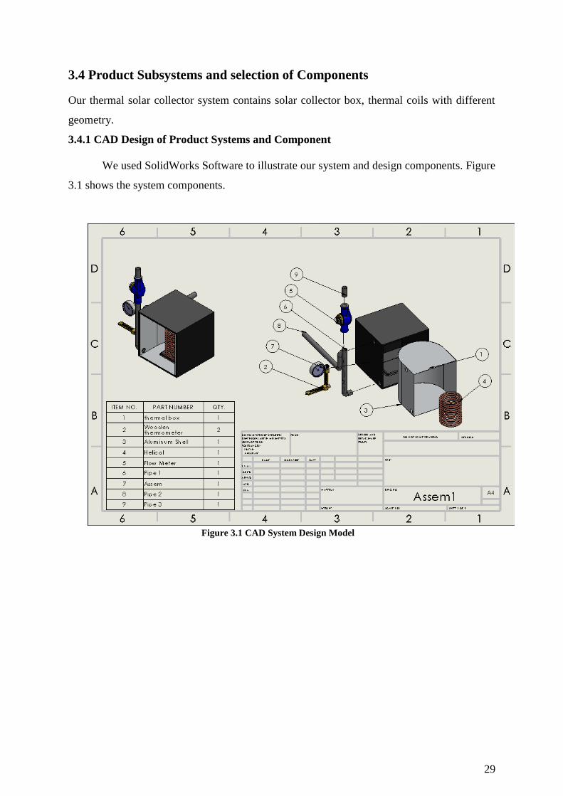
3.4 Product Subsystems and selection of Components
Our thermal solar collector system contains solar collector box, thermal coils with different
geometry.
3.4.1 CAD Design of Product Systems and Component
We used SolidWorks Software to illustrate our system and design components. Figure
3.1 shows the system components.
Figure 3.1 CAD System Design Model 8
Page 30
30
We designed 4 geometrical copper tubes. Figure 3.2 shown the coils pipes. There are four
different types of the coils pipes. We considered in our design that the four coils have a same
pitch, pipe diameter, pipe thickness, pipe outer, inner area and length.
Figure 3.2 displayed four different types of coils geometry
Page 31
31
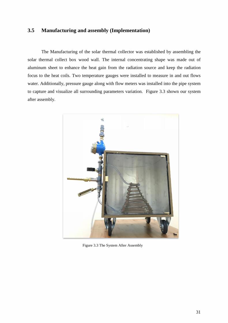
3.5 Manufacturing and assembly (Implementation)
The Manufacturing of the solar thermal collector was established by assembling the
solar thermal collect box wood wall. The internal concentrating shape was made out of
aluminum sheet to enhance the heat gain from the radiation source and keep the radiation
focus to the heat coils. Two temperature gauges were installed to measure in and out flows
water. Additionally, pressure gauge along with flow meters was installed into the pipe system
to capture and visualize all surrounding parameters variation. Figure 3.3 shown our system
after assembly.
Figure 3.3 The System After Assembly 9
Page 32
32
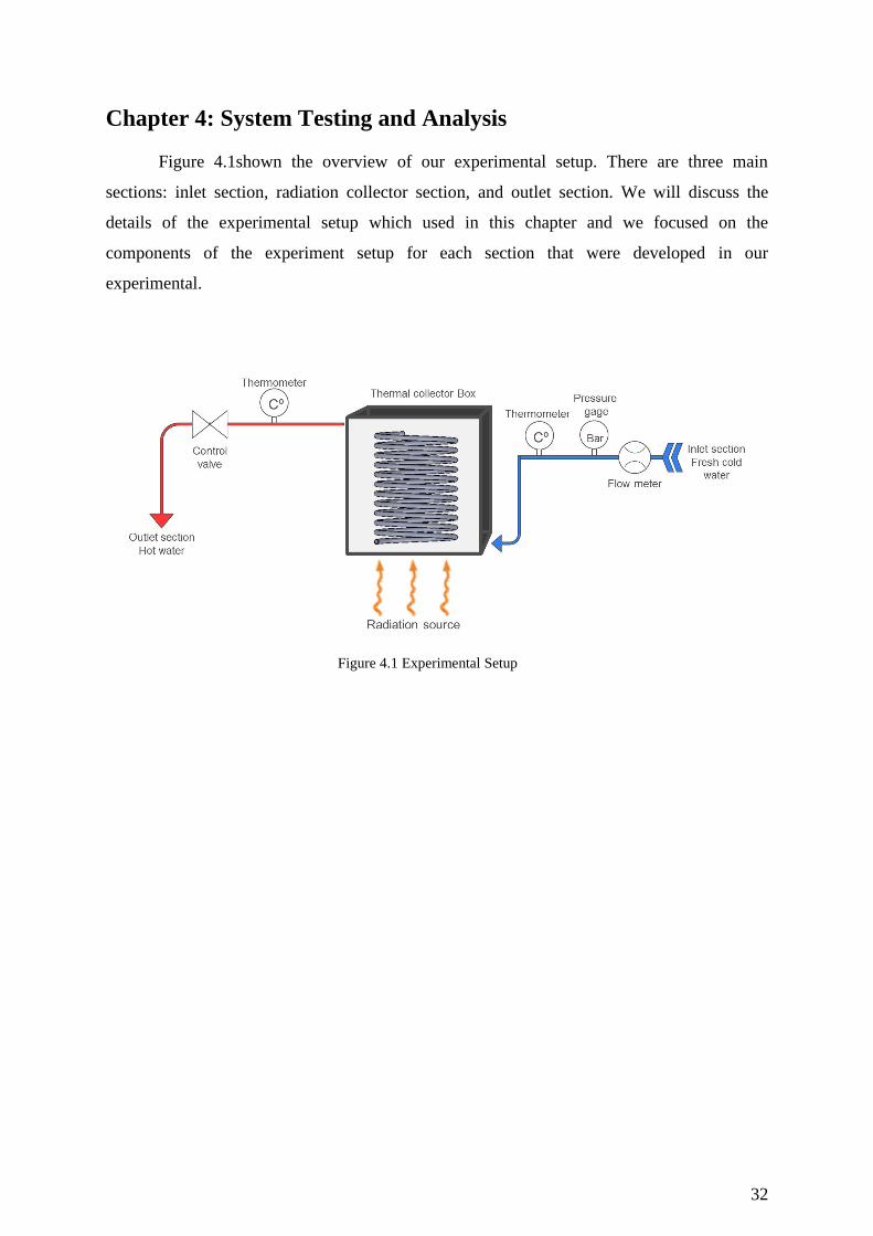
Chapter 4: System Testing and Analysis
Figure 4.1shown the overview of our experimental setup. There are three main
sections: inlet section, radiation collector section, and outlet section. We will discuss the
details of the experimental setup which used in this chapter and we focused on the
components of the experiment setup for each section that were developed in our
experimental.
Figure 4.1 Experimental Setup 10
Page 33
33
4.1 Experimental Setup, Sensors and data acquisition system
4.1.1 Inlet section
The inlet section consists of three main sensors as shown in figure 4.1. They are flow
meter, pressure gage and thermometer. As showing in figure 4.2, the first device on inlet
section is the flow meter and it used to measure the quantity of fluid moving through a pipe to
give us the volume of fluid during the experiment. We used this device in order to calculate
the mass flow rate. The second device is the pressure gage and it is used to measure the
pressure in the system. The third device is the thermometer and it is used to measure the
temperature for inlet flow.
Figure 4.2 Sensors places 11
Page 34
34
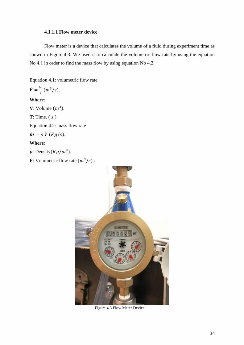
4.1.1.1 Flow meter device
Flow meter is a device that calculates the volume of a fluid during experiment time as
shown in Figure 4.3. We used it to calculate the volumetric flow rate by using the equation
No 4.1 in order to find the mass flow by using equation No 4.2.
Equation 4.1: volumetric flow rate
.
Where:
V: Volume
T: Time. (
Equation 4.2: mass flow rate
.
Where:
: Density .
: Volumetric flow rate ( .
Figure 4.3 Flow Meter Device 12
Page 35
35
4.1.1.2 Pressure Gauge
Pressure gauge is a device that gives a reading for the pressure of the flow inside the
PV pipe. We used the pressure gauge to monitor the flow pressure in the system because the
pressure might be affected by temperature of fluid. Figure 4.4 is shown the pressure gauge.
Figure 4.4 Pressure Gauge 13
Page 36
36
4.1.1.3 Thermometer Device
Thermometer is device that measures the temperature of fluid as showing in figure
4.5. We used it to measure the inlet and outlet temperature of the flow to calculate ∆T. we use
the temperature difference to calculate the heat transfer for each coil.
Figure 4.5 Thermometer14
Page 37
37
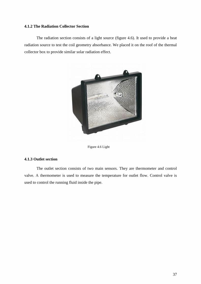
4.1.2 The Radiation Collector Section
The radiation section consists of a light source (figure 4.6). It used to provide a heat
radiation source to test the coil geometry absorbance. We placed it on the roof of the thermal
collector box to provide similar solar radiation effect.
Figure 4.6 Light 15
4.1.3 Outlet section
The outlet section consists of two main sensors. They are thermometer and control
valve. A thermometer is used to measure the temperature for outlet flow. Control valve is
used to control the running fluid inside the pipe.
Page 38
38
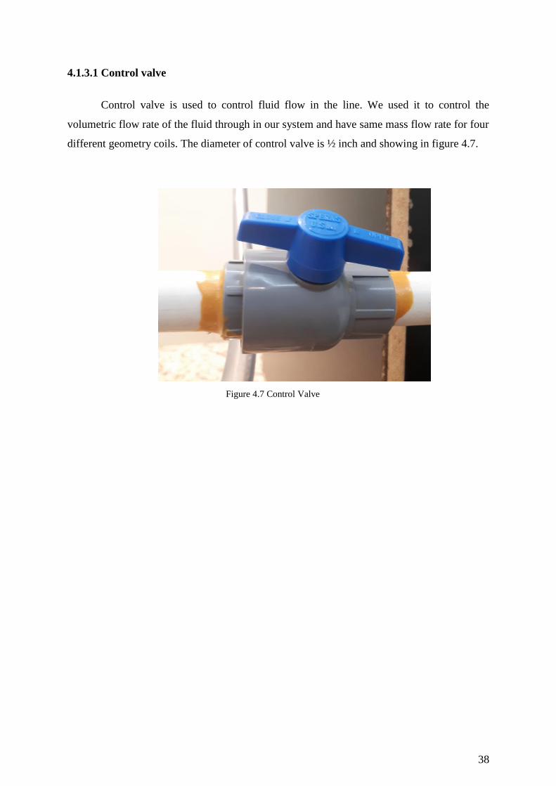
4.1.3.1 Control valve
Control valve is used to control fluid flow in the line. We used it to control the
volumetric flow rate of the fluid through in our system and have same mass flow rate for four
different geometry coils. The diameter of control valve is ½ inch and showing in figure 4.7.
Figure 4.7 Control Valve 16
Page 39
39
4.2 Results, Analysis and Discussion
4.2.1 Goals:
The aim of this experiment is to study the effect of heat radiation using different coil
geometries. After performing this experiment, we are expecting to identify if the different
coil geometries will give us the same temperature difference or not. In addition, we were
expected to be able to recommend the geometry that gives the best efficiency. On the other
hand, if we get the same temperature difference from all coils geometries we will know that
the geometry does not effect on efficiency of heat transfer by radiation.
4.2.2 Experimental methodology
1. Measuring device:
It is the gauge that we utilized for taking the temperature of the fluid on the inlet and outlet
sections of the system. We connected the temperature gauges (thermometers) to the fluid pipe
through elbows that enables us to take the temperature readings from inside the pipe.
2. Heat radiation source
It used to provide a heat radiation source to test the coil geometry absorbance. We placed it
on the roof of the thermal collector box to provide similar solar radiation effect.
3. Flow controller:
It is used to control the running fluid inside the pipe. We placed it at the outlet section to
control the volumetric flow rate of the fluid through the pipe in the system.
4.2.3 Errors and Challenges
While building up the solar thermal collector we faced many errors and challenges.
We tried to run the system using a small water pump but it was not pumping sufficiently.
Consequently, we modified the system and used direct water flow instead of the water pump.
The second error we faced when we tested the system with glass door. The glass door
did handle the heat radiation and it broke while we are conducting the experiment. After that
we modified the system to perform the system with direct heat radiation without glass door.
Page 40
40
Third error is that the copper coil was not painted which resulted in reflecting the heat
radiation. As a result we painted the coil in black color to increase the heat radiation
absorbance.
4.2.4 Experimental procedure
The below procedure guides us to perform the experiment and test all of the four
different coil geometries:
1. Start the experiment by connecting inlet section to water supply line. After that, open the
water supply to run the system.
2. Check the water flow in the system and make sure to release all air from system.
3. make sure that all connections are sealed and check system for leakage.
4. Close the control valve.
5. Switch on the heat radiation source (light).
6. Make sure that the radiation is directed to the coil geometry.
7. Wait for 5 minutes.
8. Open the control valve gradually and monitor the exit temperature until becomes stable.
9. Take a reading for the volume from the flow mater.
10. Take the temperature readings from the inlet and exit thermometers.
11. Take the reading again every minute. Total 5 reading.
12. Close the water supply and switch off the light.
13. Replace the coil to start testing the other coil geometries.
The figure 4.8 shows the coils wheel we performed the experimental for each coil.
Figure 4.8 coils while the experiment 17
Page 41
41
4.2.5 Results and Discussions
By performing the experiment, we list a table that shows all results. Table 4.1 is
showing the water volume reading during time. As we have a flow meter and control valve,
we fixed the volume quantity of the fluid that passed through the system for all coils
geometries and we got same flow meter for all of them. We will use equitation 4.1 and 4.2 to
calculate volumetric flow rate and mass flow rate as below:
Table 4.1 The water volume reading7
Time (s) Volume ( ) .
0 0 1000
55 0.002 1000
110 0.0039 1000
165 0.0060 1000
Equitation 4.1: Volumetric Flow Rate
.
.
Equitation 4.2: Mass Flow Rate
.
.
Page 42
42
Table 4.2 is showing the results of testing the solar thermal collector system. The
table shows the temperature difference as a function of time. In this table we took the fluid
temperature from the inlet and outlet sections of the system. We tested the four copper coil
geometries each at a time under the same room conditions. We are using equation 4.3 to
calculate the total heat transfer as below:
Table 4.2 The Test Results 8
Item ( )
Barrel 27 30
Constant Pitch 27 30
Hour Glass 27 30
Conical 27 30
Q = [ ]
So the total heat capacity for four deferent coils as below:
Q = (4.1855) ( ) (30-27) = 0.4565 KW
Figure 4.9 The Test Results 18
In this experiment, we had compared the temperature differences among different
copper coil geometries. Figure 4.9 depicts the shape of the copper coil vs. the temperature.
Page 43
43
The temperature increased by 3 for all copper coil geometries. We also figured out from
our experiments that all different coil geometries have same ∆T.
Page 44
44
4.3 modeling of temperature difference ∆T of coils:
We studied in this section the theoretical radiation heat transfer for coils on our
project. We have three enclosures surface light source, coils, surrounding. The figure 4.10 is
showing schematic of three surfaces enclosure.
Figure 4.10 schematic of three surfaces enclosure 19
Where:
1: The light source.
2: Coil surface.
3: Surrounding surface.
The figure 4.11 is showing the draw surface resistances associated with each of three
surfaces and connect with space resistances. Where we assume three assumption of
emissivity:
Where:
: Light emissivity = 0.02.
: Black copper coil emissivity = 0.98.
: surrounding emissivity = 0.09.
Figure 4.11 the radiation network associated with surfaces.
Page 45
45
We used the equations from the previous page to do our calculations. Table 4.3 is
showing the results of our calculations. The table contains temperature (T), Area (A), and
emissivity ( ).
Table 4.3 Radiation Test Results 9
Surface T(ᵒ K) A ( ) R J (W/ )
1- Light 1350 188329.4044 9174.34 7482.47
2- Coil 308 0.2262 510.2534 0.09022 655.64
3- Surrounding 300 0.887 459.27 11.39 5728.92
Page 46
46
4.3.1 Calculation of view factor
Radiation heat transfer between surfaces depend on the rate of heat exchange between
of them. It considers the surface temperature and emissivity for each surface.
The view factor from a surface i two surface of j is denoted by .
Where:
= The fraction of the radiation leaving surfaces i that strike surface j directly.
We will use equitation 4.3 and 4.4 to find the summation rule for each of the three surfaces
gives:
Equitation 4.3
Noting that
Equitation 4.4
We did the calculation of view factor. The results of the calculations are in table 4.5
below.
Table 4.5 View Point Calculations 10
0.38 0.62
0.8976 0.1024
0.30364 0.00212
4.3.2 Calculation of net heat transfer radiation
During a radiation interaction, a surface losses energy by emitting radiation and gains
energy by absorbing radiation emitted by other surfaces. A surface experience a net gain or a
net loss of energy depending on the quantity is larger. The net rate of radiation heat transfer
from a surface i of surface area Ai is denoted by Qi as we use it in equitation 4.5 for each
Page 47
47
surface. We will apply also equitation 4.5 to each surface to determine the radiosities in
system.
Equitation 4.5
Equitation 4.6
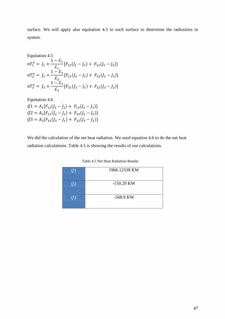
We did the calculation of the net heat radiation. We used equation 4.6 to do the net heat
radiation calculations. Table 4.5 is showing the results of our calculations.
Table 4.5 Net Heat Radiation Results 11
1966.12338 KW
-150.29 KW
-568.9 KW
Page 48
48
4.3.3 Calculation of theatrical ∆T
= 190 ᵒK.
= 3 ᵒ K.
The big different between theoretical and experiment returned to scattered of radiation
is very high. If we have concentrated (leans), of course ∆T could reach at least close to 100
ᵒK.
Page 49
49
Chapter 5: Project Management
5.1 Project Plan
During the semester we identified the tasks needed in order to complete the senior project
design. We made a table called Gantt hart to put all the tasks that the team need to should do.
In this table there is activity, tasks, responsibility, duration, and percent complete. Table 5.1
is showing the project plan.
Table 5.1 Gantt Chart 12
ACTIVITY Tasks Responsible Duration Percent
Complete
Intr
oduct
ion
Project
allocation +
introduction
Project
Definition
Marwan 1 Week 100%
Project
Objectives
Project
Specifications
Applications
Literature
Review
Project
background
All Team 3 Weeks 100% Previous Work
Comparative
Study
Syst
em D
esig
n Design
Design
Constraints and
Design
Methodology
Omar 2 Weeks 100%
Equipment
and material
selection
(3.4)
selected the
appropriate
items
Ibrahim +
Meshal 2 Weeks 100%
Page 50
50
Theory and
Theoretical
Calculations
main
calculations
required
detailed
calculations to
your design.
Ibrahim +
Omar 1 Week 100%
Prototype
assemble
System
integration,
describe ,
procedures and
Implementation
All Team 3 Weeks 100%
Syst
em T
esti
ng a
nd A
nal
ysi
s
Testing and
analyses
Experimental
Setup, Sensors
and data
acquisition
system All Team 2 Weeks 100%
Results,
Analysis and
Discussion
Pro
ject
Man
agem
ent
and
Pro
ject
Anal
ysi
s
Project
Management
Project Plan
All Team 2 Weeks 100%
Contribution of
Team Members
Project
Execution
Monitoring
Challenges and
Decision
Making
Project Bill of
Materials and
Budget
Project
Analysis
Life-long
Learning
All Team 1 Week 100% Impact of
Engineering
Solutions
Page 51
51
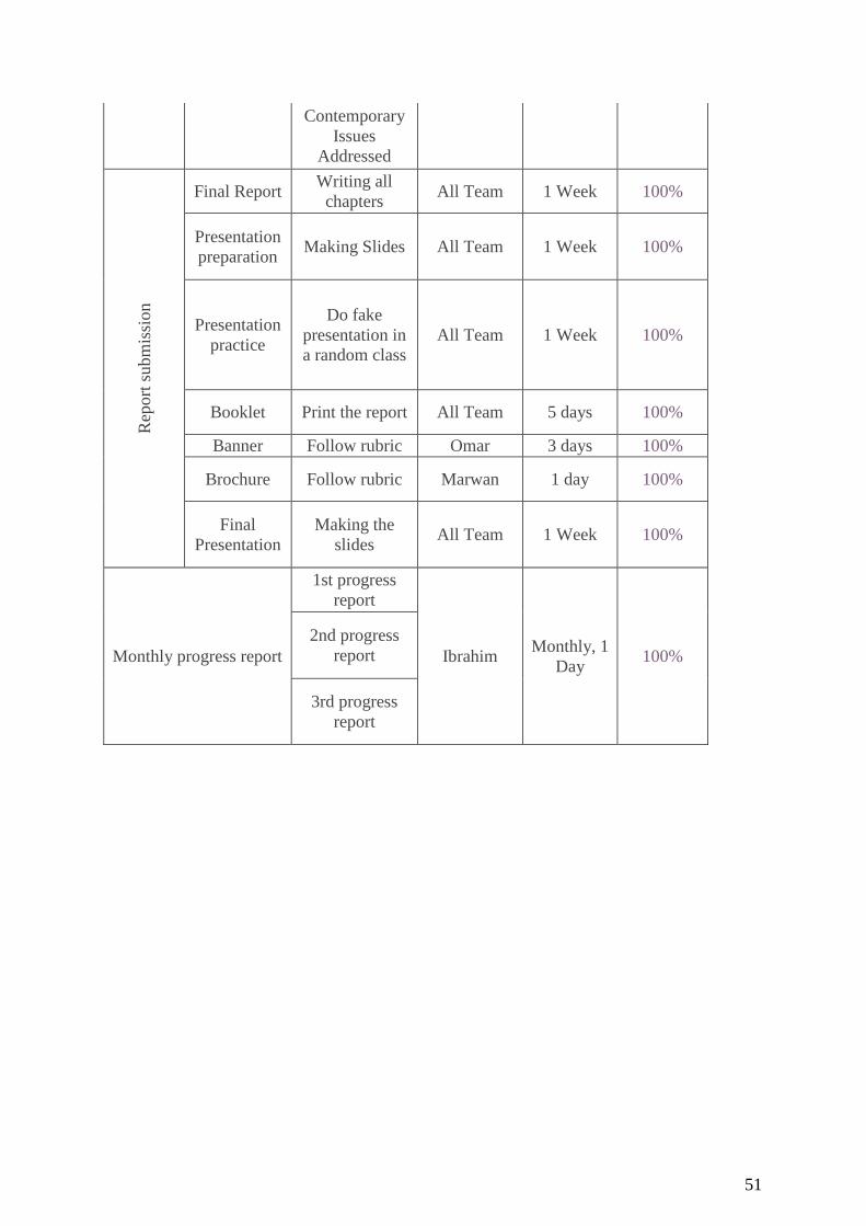
Contemporary
Issues
Addressed R
eport
subm
issi
on
Final Report Writing all
chapters All Team 1 Week 100%
Presentation
preparation Making Slides All Team 1 Week 100%
Presentation
practice
Do fake
presentation in
a random class
All Team 1 Week 100%
Booklet Print the report All Team 5 days 100%
Banner Follow rubric Omar 3 days 100%
Brochure Follow rubric Marwan 1 day 100%
Final
Presentation
Making the
slides All Team 1 Week 100%
Monthly progress report
1st progress
report
Ibrahim Monthly, 1
Day 100%
2nd progress
report
3rd progress
report
Page 52
52
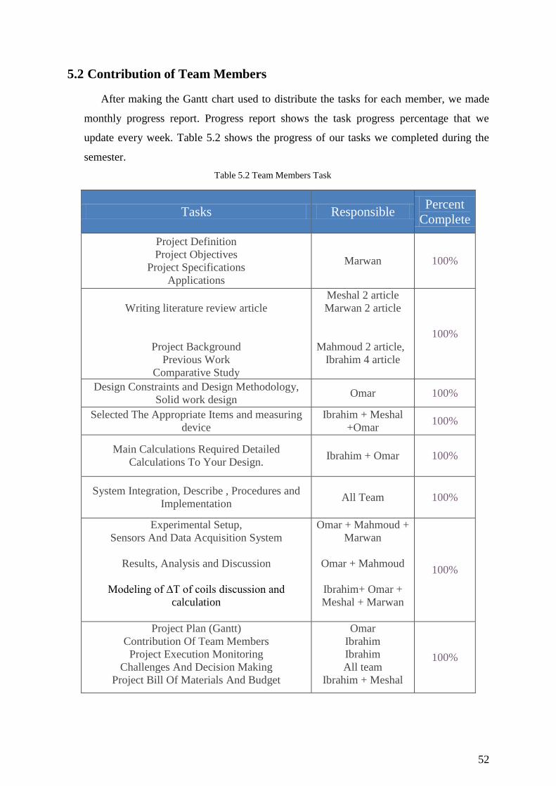
5.2 Contribution of Team Members
After making the Gantt chart used to distribute the tasks for each member, we made
monthly progress report. Progress report shows the task progress percentage that we
update every week. Table 5.2 shows the progress of our tasks we completed during the
semester.
Table 5.2 Team Members Task 13
Tasks Responsible Percent
Complete
Project Definition
Project Objectives
Project Specifications
Applications
Marwan 100%
Writing literature review article
Project Background
Previous Work
Comparative Study
Meshal 2 article
Marwan 2 article
Mahmoud 2 article,
Ibrahim 4 article
100%
Design Constraints and Design Methodology,
Solid work design Omar 100%
Selected The Appropriate Items and measuring
device
Ibrahim + Meshal
+Omar 100%
Main Calculations Required Detailed
Calculations To Your Design. Ibrahim + Omar 100%
System Integration, Describe , Procedures and
Implementation All Team 100%
Experimental Setup,
Sensors And Data Acquisition System
Results, Analysis and Discussion
Modeling of ∆T of coils discussion and
calculation
Omar + Mahmoud +
Marwan
Omar + Mahmoud
Ibrahim+ Omar +
Meshal + Marwan
100%
Project Plan (Gantt)
Contribution Of Team Members
Project Execution Monitoring
Challenges And Decision Making
Project Bill Of Materials And Budget
Omar
Ibrahim
Ibrahim
All team
Ibrahim + Meshal
100%
Page 53
53
Life-Long Learning
Impact Of Engineering Solutions
Contemporary Issues Addressed
Ibrahim + Meshal 100%
Slides preparation All Team 100%
Perform dry run presentation All Team 100%
Design of project slides PowerPoint and video
record and editing Omar 100%
Design of brochure and Poster Mahmoud 100%
1st Progress Report
2nd Progress Report
3rd Progress Report
Ibrahim 100%
5.3 Project Execution Monitoring
During the period of 4 months we set up meetings with our advisors, meetings with
the team member, and meetings for testing. We set up meetings with our advisors to help us
if we were facing a problem in the project, and to teach us to write the report. Also, we set up
meetings with the team members to plan for the design project. In our senior design project it
is required to do a test based on about our project. Table 5.3 is showing the dates of meetings
with our advisors, team member, and meetings to do the test.
Table 5.3 Project Monitoring 14
Month January February March April
Meetings with advisors 10-17-24-31 7-14-21-28 7-14-21-28 4-11-18-25
Meeting with the team members 9-16-23-30 6-13-20-27 6-13-20-27 3-19-17-24
Testing - - - 1 to 20
5.4 Challenges and Decision Making
During this semester we had a problems such as getting the parts, assembly, and
during the experiment. with the getting the heat form the heater. Also, we had some issues
with our team members in the case of establishing our meetings, because we had classes that
are different from member into other members. All the team member have jobs, so it was
difficult for us to have the work done. However, we had another sort of problem which is the
time, because there is no much time to finish all the challenges and objectives that we are
seeking for, and that was good experience to overcome the challenges.
Page 54
54
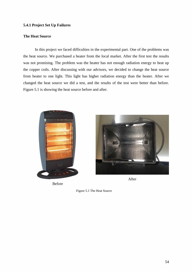
5.4.1 Project Set Up Failures
The Heat Source
In this project we faced difficulties in the experimental part. One of the problems was
the heat source. We purchased a heater from the local market. After the first test the results
was not promising. The problem was the heater has not enough radiation energy to heat up
the copper coils. After discussing with our advisors, we decided to change the heat source
from heater to one light. This light has higher radiation energy than the heater. After we
changed the heat source we did a test, and the results of the test were better than before.
Figure 5.1 is showing the heat source before and after.
Before
After
Figure 5.1 The Heat Source 20
Page 55
55
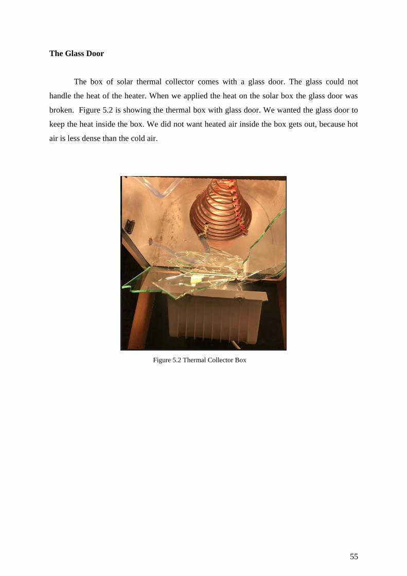
The Glass Door
The box of solar thermal collector comes with a glass door. The glass could not
handle the heat of the heater. When we applied the heat on the solar box the glass door was
broken. Figure 5.2 is showing the thermal box with glass door. We wanted the glass door to
keep the heat inside the box. We did not want heated air inside the box gets out, because hot
air is less dense than the cold air.
Figure 5.2 Thermal Collector Box 21
Page 56
56
Copper Coils
In order to make the copper coils absorb more heat we painted them with black color.
The reason is a black body absorbs all that fall on its surface, so it will increase the heat of
the water inside the copper coils. After the paint job of the copper coils we tested it, and the
result was good. Figure 5.3 shows the copper coils after the pain job.
Figure 5.4 Copper Coils after Paint Job22
Page 57
57
Instable Flow
The flow of the water inside the copper coils was not stable. To fix this problem we
put a control valve to keep the water in the piping stable. We want the rate volume of the
water the same in every test, so the control valve helped us to keep the rate of volume
constant. Figure 5.5 is showing the control valve.
Figure 5.5 Control Valve 23
Page 58
58
5.5 Project Bill of Materials and Budget
We listed all the expenses incurred in order to complete our project. We purchased
many parts and we went to workshops to complete our design. Table 5.3 is showing all the
parts that we purchased, and the labor cost.
Table 5.3 Expenses of Material and Labor Work15
Item Price SR
MDF plate 90
Assembly Labor 50
Labor cut 15
Glass 100
Labor work glass 50
4 Tires 32
Handle 6
Aluminum Foil 50
Aluminum Sheet bended 150
Nails 5
Glue 11
Hose 20
Clips 2
Thermometer 250
Heater 120
Control Valve 15
Fitting PVC 30
10m Hose 30
Light 60
PVC Pipes 50
Copper Coil with Labor 500
Banner 150
Books 300
Brochure Poster 50
Pump 45
Total 2181
Page 59
59
Chapter 6: Project Analysis
6.1 Life-long Learning:
There are so many great lessons we all learn from project’s life. We are as a group
made a list with some of the most important ones so far, lessons that had a great impact in
project’s life. The challenges and opportunities that we have faced during this project have
helped us discover some hidden abilities that we had not been able to explore in the past. One
of the assignments of the group is to meet once a week and discuss previous problems, some
of activities that related to the project. We review reports and provide comment. By joining a
group, you will fuel your interests, challenge and reinforce your learning, Brainstorming, and
have the opportunity to ask questions. Our comments are then forwarded to our instructor to
give the final approve. Even though all of us improved our knowledge, skills and abilities in
different ways, we can summarize our overall learning experience using the following
sections.
6.1.1 Improve our Skills in Sensors Tools
In this project we had use many of sensors such as thermometer, flow meter, pressure
gauge. There are many different types of thermometer availa le in today’s market, we used
show different types one of them to measure the inlet temperature and the other on is to
measure the outlet temperature. We believe it is important to choose the right thermometer to
suit our intended application. Moreover flow meter one of the most common flow
measurement mistakes is the reversal of this sequence: instead of selecting a sensor which
will perform properly, an attempt is made to justify the use of a device because it is less
expensive therefor we selected the right one to avoid any mistakes. Finally, we used flow
meter, they are many types of gauge styles, they are many types of gauge styles, the most
common being Bourdon tubes and bellows gauges, we used simple one to be easy for
calibrate and maintain.
6.1.2 New Tools Helped With The Research
We used various tools to help complete this project. we used some applications such
as solid work and Microsoft of power point. Solid work program which helps to create 2D or
3D solids models without any complexity, faster and in the cost effective way. It assists us to
Page 60
60
create models and assemblies. On other hand, the importance of explanation and presentation
in learning skills are two processes cannot be separated therefor we used power point to
summary our senior project because explanation alone is not enough and presentation alone is
not enough and are not influential in the process of learning fully. We used Google Scholar
website to look for articles similar to our research. Also we used science direct website to
look for articles similar to our research. These tools will help us to do research in the future.
We also read the heat transfer book to learn about our project.
6.1.3 Project management skills
Management skill is very important skill. In order to finish the project in time and
ensure that our objectives were accomplished, we had to be managers of our own. We’ve
trimmed our project management skills list to just five areas that we think it’s important to
master to be an effective project, here is our short list of some skills for our project
management, leadership, communication, planning skills, time management, and Subject
matter expertise. Creating realistic project plans, budgets, estimating time and effort, etc. are
all things that a good project manager must do. We keep our work organized and our teams
informed and happy to success and achieve the main goal. We also improved our
collaboration and coordination skills. We subdivided the project to various tasks and each one
had to undertake certain tasks, which we later met and collaborated to come up with the final
project.
6.2 Impact of Engineering Solutions
This project is about the solar thermal collector. We want to optimize a geometry that absorbs
heat. Using the sun as a source of energy would affect the economy, society, and
environment. We will explain the impact of each of them in details.
6.2.1 Economy
The impact of our project has an effect on the economy side, due to simplicity and the high
efficiency of the solar thermal collector. It’s economical water heater with the usage of the
radiation as an energy source. The solar thermal collector offers a cheaper source of energy
for households because they will be harnessing solar energy, which is cheaper compared to
Page 61
61
other sources of energy in the country. As such several, households will be able to make
savings that may be utilized for other purposes and in the process of raising the living
standards. Our solar thermal collector has a comparatively free maintenance cost since it can
be used for longer period of time without any frequent repairs.
6.2.2 Society
Society it is the most important driver in this project, since Saudi Arabia government
motivate the society to utilize the renewable energy source, and solar energy is one of them.
The solar thermal collector can be used in communities and industries to reduce the power
consumption which would result to a reduce the load on power plants.
6.2.3 Enviorment
The solar thermal collector is an alternative solution to produce renewable energy. This
design could help to reduce the use of polluting power generation. Our study is heating water
using solar thermal collector. It’s an environmentally friendly device, and it’s a useful tool
that will help to reduce the carbon emissions as well as the from environment as.
6.3 Contemporary Issues Addressed
Electricity consumption is one of our project concerns. Our project objective is to
reduce the power consumption. The solar thermal collector provides an alternative source of
power that will offer people another solution, instead of relying on the conventional power
suppliers. The issue of global warming has been another challenge across the world. In Saudi
Arabia, a larger percentage of the electricity supplied utilizes non-renewable sources that
increase pollution adding to the problem of global warming. Solar collector is eco-friendly,
reduces the air pollution. Also it saves money, because it reduces the electric use for the
power plant.
Page 62
62
Chapter 7: Conclusions and Future Recommendations
7.1 Conclusions
Affordable and reliable energy has become a main focus and challenge in the recent
world following the increase in the demand of energy both for domestic and industrial use.
This demand has seen a scramble for energy between the domestic and the industrial sectors
in which the domestic sector has at times have to bear with shortages due to the increased
demand in the industrial sector. This is in reference to the need for electricity for heating
water used for the purposes for bathing in the domestic sector.
The team was driven by the desire to make energy available and more affordable for the
domestic sector to use for the purposes, which to some extent are not perceived to be very
important to the industrial sector. In this light, the team borrowed an idea from the heat
exchanger, how it operates and the underlying principles. The influence of the geometric
structure of a coil formed the main point of focus and thus of interest for the team which
aimed at availing enough energy to the families through the heat exchanger.
The experiment met the objectives which were designing a test rig coil in different
geometries and then designing a number of coil geometries. Furthermore, designing
experiments to study the best coil geometry efficiency in heat transfer. Whereas there were a
number of challenges in the process of performing the experiment in relation to the technical
and legal aspects of the experiment, achievements were made in relation to the aims and
objectives. Based on the various test results, each of the objectives of the experiment was
achieved. The test results on the volume of water reading during time were used in
establishing the efficiency of the control valves and the flow meter in which the volume
quantity of water that passed through the system was fixed for all the different coil
geometries. A calculation of the volumetric flow rate and mass flow rate was used for the
Page 63
63
purposes of making comparison between the different coil geometries in order to establish
which geometry was more efficient. Another test was done on the solar thermal collector
systems using the four different copper coil geometries each of them at a time under the same
conditions of temperature and pressure. The results established illustrated that the entire
different coil geometric had the same change in temperature throughout this experimental
research.
7.2 Future Recommendations
The project can incorporate a number of adjustments or modifications in order to
increase its usage and benefit to the day-to-day lives of the members of a society. The project
does not specify the size of the solar panels used in the experiment. To make it clearer and
broaden the objective of the project, the use of high wattage solar panels in encouraged.
Through the high wattage solar panels, the amount of energy supplied will be higher and
hence raising the levels of reliability of the energy source. On the same note, solar panels of
high wattage would maximize the solar radiation produced such that the energy supply can be
continued even the absence of solar radiation. This happens in such a way that the
photovoltaic cells of the solar panel would ensure maximum trapping of the solar radiation
and conversion into electricity.
Solar energy is an eco-friendly source of energy whose use should not only be limited
to the domestic set up. The project can thus be expanded in such a way that the solar panels
used in the project are projected to the national grid where the project can as well supply
power for use in the industries. This will in turn increase environmental sustainability as well
as help in increasing the supply of energy. There will as well be economic benefits that are
accrued by using the project in the industries especially when it is used in running such
equipment as boilers that consume a lot of energy at ago.
Page 64
64
8. References
[1] Borkar, M. D., Prayagi, D., & Gotmare, M. J. (2014). Performance Evaluation of
Photovoltaic Solar Panel Using Thermoelectric Cooling. International Journal of
Engineering Research,3(9), 536-539. doi:10.17950/ijer/v3s9/904
[2] Khan Abu Mustafa. Khan Naseem A. (2013). Spiral Coil Heat Exchanger. S.L.: Lap
Lambert Academic Publ.
[3] Perini, S., Tonnellier, X., King, P., & Sansom, C. (2017). Theoretical and experimental
analysis of an innovative dual-axis tracking linear Fresnel lenses concentrated solar
thermal collector. Solar Energy, 153, 679-690. doi:10.1016/j.solener.2017.06.010
[4] Puttewar, A. S., & Andhare, A. M. (2015). Design and thermal evaluation of shell and
helical coil heat exchanger. International Journal of Research in Engineering and
Technology, 416 23.
[5] Pramanik, S., & Ravikrishna, R. (2017). A review of concentrated solar power hybrid
technologies. Applied Thermal Engineering,127, 602-637.
doi:10.1016/j.applthermaleng.2017.08.038
[6] Phelan, P., Otanicar, T., Taylor, R., & Tyagi, H. (2013). Trends and Opportunities in
Direct-Absorption Solar Thermal Collectors. Journal of Thermal Science and
Engineering Applications,5(2), 021003. doi:10.1115/1.4023930
[7] Moravej, M., & Soozanyar, A. (2017). An Experimental Investigation of the
Efficiency of A Stationary Helical Solar Water Heater. Current World
Environment,12(2), 250-257. doi:10.12944/cwe.12.2.08
[8] Lv, Y., Si, P., Liu, X., Rong, X., Feng, Y., & Yan, J. (2016). An Optimized Model for
Solar Thermal Collectors Based on Concept of Effective Heat Collection. Energy
Procedia,88, 470-475. doi:10.1016/j.egypro.2016.06.037
[9] Qvistgaard, L. H. (2014). Energy-economic optimization of heating system with solar
collectors (Master's Thesis). Norwegian University of Science and Technology,
Norway.
[10] Jassim, E., Thunayan, H., Alshehri, M., & Alharbi, M. (2016). Geometry optimization
for high efficient coiled Heat Exchanger.
Page 65
65
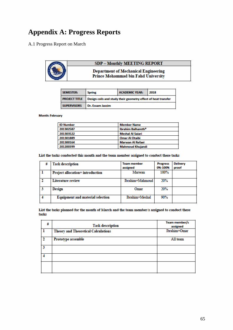
Appendix A: Progress Reports
A.1 Progress Report on March
Page 68
68
A.2 Progress Report on April
Page 71
71
Appendix B: Engineering standards
Engineering standards are important. In every component of our design we looked in
the engineering standards for the best material for the system. Table B.1 is showing the
material we purchased for our project.
Table B.1 Engineering Standards 16
No. Part name Type of Material Reference
Standards Standards Description
1 Coils Copper of Alloy
C12200
ASTM B88
and ANSI/
NSF 61
Seamless Copper Water Tubes
2 Piping
connection CPVC ASTM D2846 Plastic Hot Water Distribution Systems
3 Thermal box MDF Wood ASTM D5664
- 17
Wood of Elevated Temperatures
Surface
4 Collector
window Glass
ASTM E765-
80 Flat Plate Solar Collectors
5 Solar Diffuser Aluminum Alloy ASTM
B209M Aluminum-Alloy Sheet and Plate
6 Hoses
connection Thermoplastic
ASTM F645 -
15a
Thermoplastic Water- Pressure Piping
Systems
Page 72
72
Appendix C: CAD drawings and Bill of Materials
In this part we put the 2D drawings of everything we manufactured and some of the
parts we purchased. Figure C.1 is showing the exploded view, and bill of material.
Figure C.1 Exploded View
Page 73
73
Figure C.2 is showing the 4 different types of copper coils.
Figure C.2 Copper Coils 24
Page 74
74
Figure C.3 is showing the pressure gauge.
Figure C.3 Pressure Gauge 25
Page 75
75
Figure C.4 is showing the thermomter.
Figure C.4 Thermometer 26
Page 76
76
Figure C.5 is showing the pressure gauge.
Figure C.5 Flow Meter 27
Page 77
77
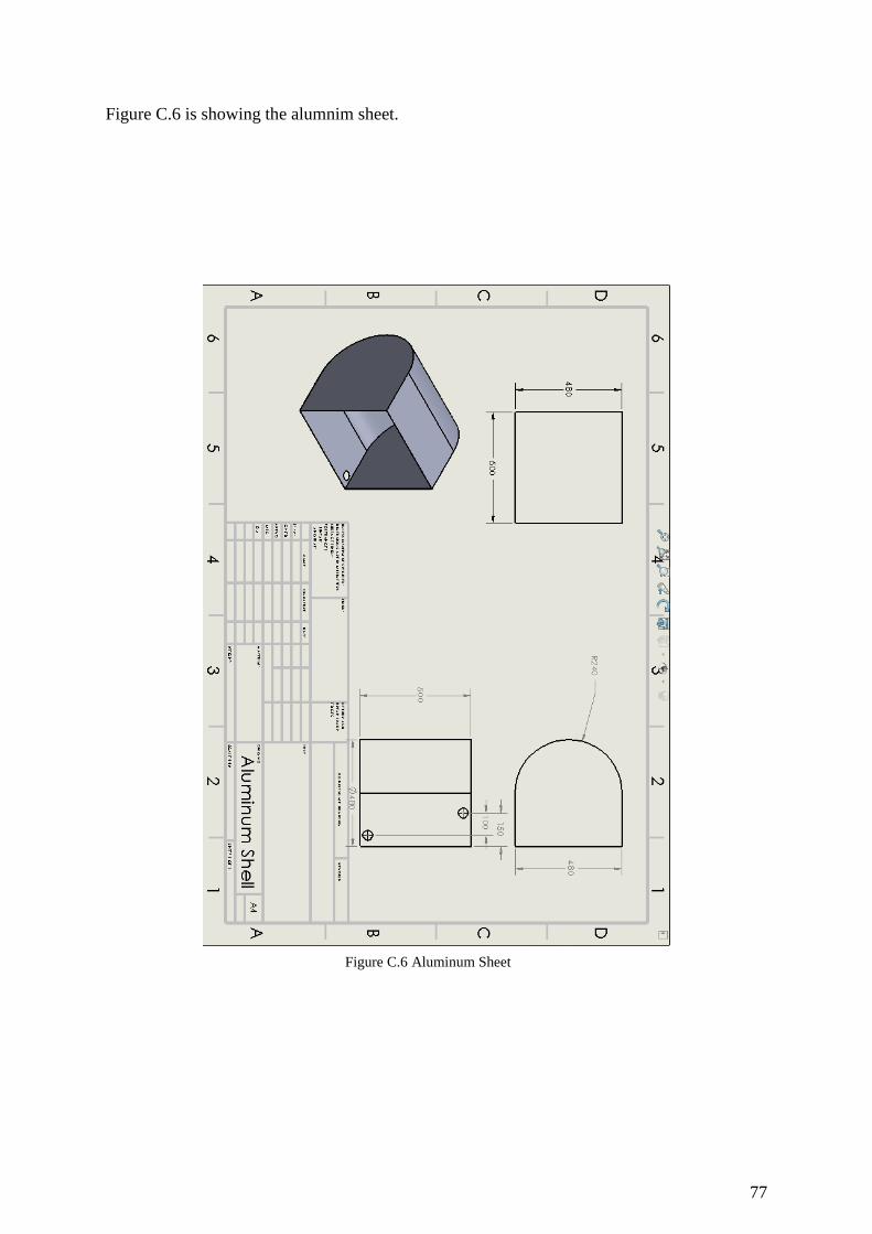
Figure C.6 is showing the alumnim sheet.
Figure C.6 Aluminum Sheet 28
Page 78
78
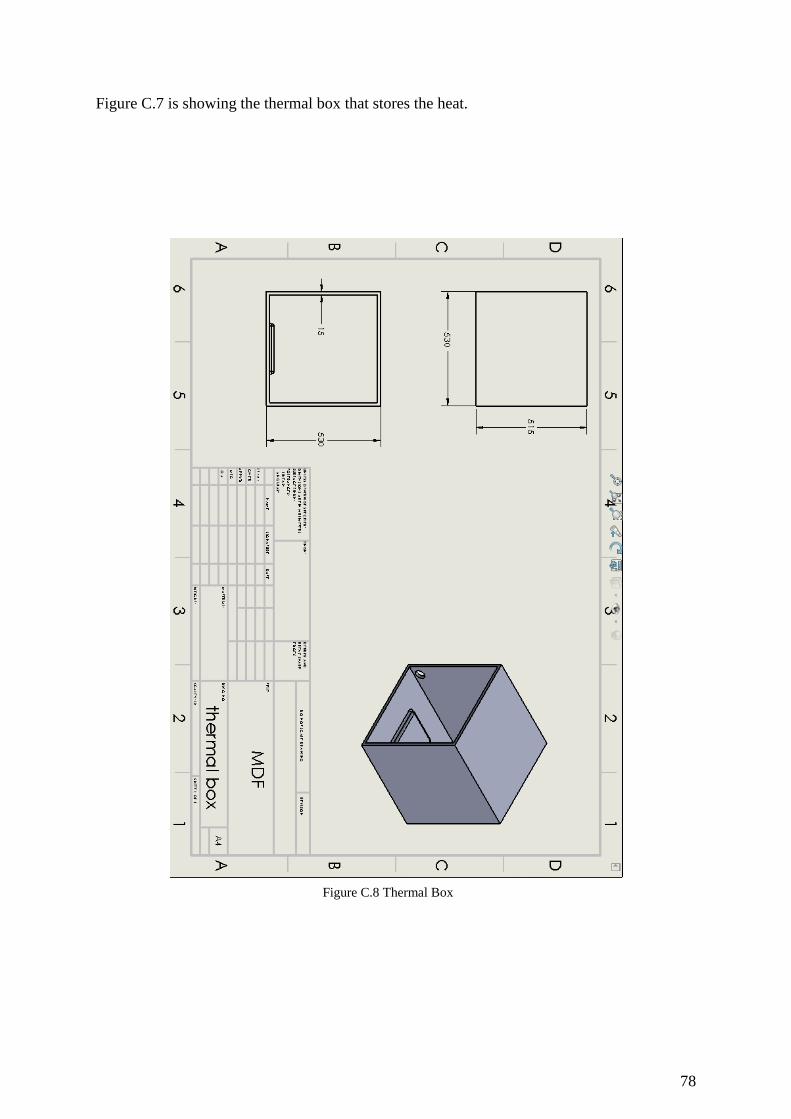
Figure C.7 is showing the thermal box that stores the heat.
Figure C.8 Thermal Box 29


![Solar Energy for Industrial Rooftops: An Economic and ... · Solar Thermal ST [2] Photovoltaic PV [1] 2 Compact linear Fresnel Collector [3] PVT Collector [4] Solar Energy for Industrial](https://static.documents.pub/doc/80x56/5e42a20e57f4800ae0102b77/solar-energy-for-industrial-rooftops-an-economic-and-solar-thermal-st-2-photovoltaic.jpg)


