46
DESIGN OF INDUCTION MOTOR 1
DESIGN OF
INDUCTION MOTOR
1
Construction of Induction Motor
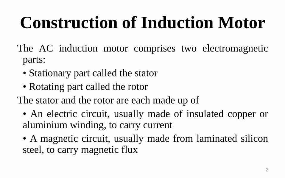
The AC induction motor comprises two electromagneticparts:
• Stationary part called the stator
• Rotating part called the rotor
The stator and the rotor are each made up of
• An electric circuit, usually made of insulated copper oraluminium winding, to carry current
• A magnetic circuit, usually made from laminated siliconsteel, to carry magnetic flux
2

3
Stator
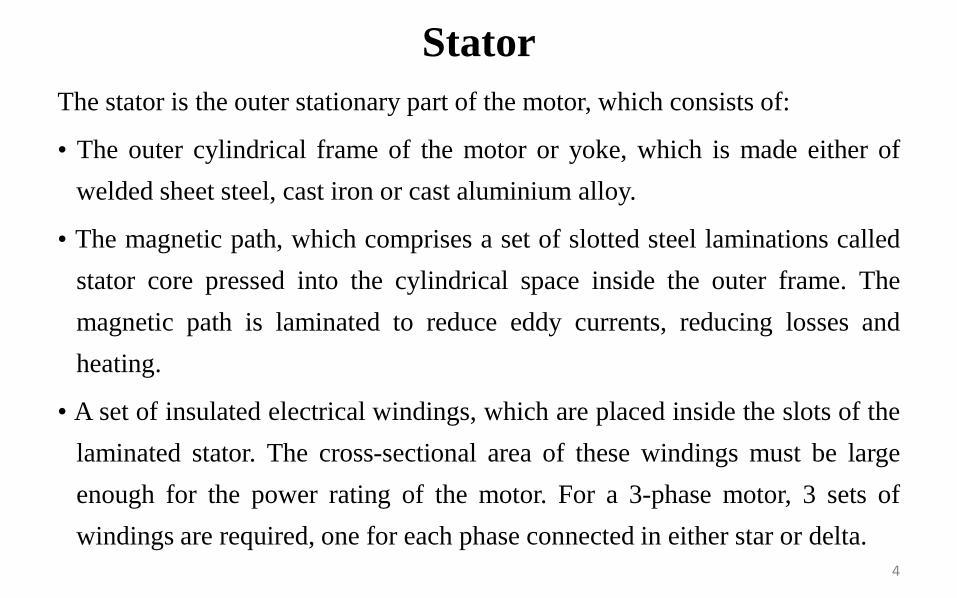
The stator is the outer stationary part of the motor, which consists of:
• The outer cylindrical frame of the motor or yoke, which is made either of
welded sheet steel, cast iron or cast aluminium alloy.
• The magnetic path, which comprises a set of slotted steel laminations called
stator core pressed into the cylindrical space inside the outer frame. The
magnetic path is laminated to reduce eddy currents, reducing losses and
heating.
• A set of insulated electrical windings, which are placed inside the slots of the
laminated stator. The cross-sectional area of these windings must be large
enough for the power rating of the motor. For a 3-phase motor, 3 sets of
windings are required, one for each phase connected in either star or delta.
4

5

Rotor
Rotor is the rotating part of the induction motor. The rotor also consists of a set
of slotted silicon steel laminations pressed together to form of a cylindrical
magnetic circuit and the electrical circuit. The electrical circuit of the rotor is
of the following nature
Squirrel cage rotor consists of a set of copper or aluminium bars installed into
the slots, which are connected to an end-ring at each end of the rotor. The
construction of this type of rotor along with windings resembles a ‘squirrel
cage’. Aluminium rotor bars are usually die-cast into the rotor slots, which
results in a very rugged construction. Even though the aluminium rotor bars
are in direct contact with the steel laminations, practically all the rotor
current flows through the aluminium bars and not in the lamination
6
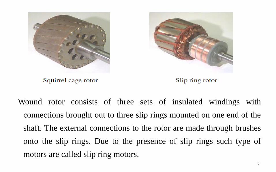
Wound rotor consists of three sets of insulated windings with
connections brought out to three slip rings mounted on one end of the
shaft. The external connections to the rotor are made through brushes
onto the slip rings. Due to the presence of slip rings such type of
motors are called slip ring motors.7
Some more parts to complete the constructional details of an induction motor,
are:
• Two end-flanges to support the two bearings, one at the driving-end and the
other at the non driving-end, where the driving end will have the shaft
extension.
• Two sets of bearings to support the rotating shaft,
• Steel shaft for transmitting the mechanical power to the load.
• Cooling fan located at the non driving end to provide forced cooling for the
stator and rotor
• Terminal box on top of the yoke or on side to receive the external electrical
connections
8

Cut sectional view of the induction motor
9
Introduction to Design
The main purpose of designing an induction motor is to obtain
the complete physical dimensions of all the parts of the
machine as mentioned below to satisfy the customer
specifications. The following design details are required.
1. The main dimensions of the stator.
2 Details of stator windings.
3. Design details of rotor and its windings
4. Performance characteristics.10
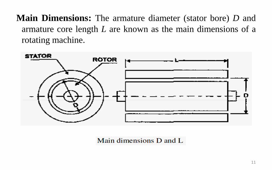
Main Dimensions: The armature diameter (stator bore) D and
armature core length L are known as the main dimensions of a
rotating machine.
11

Total Loadings:
Total Magnetic Loading : the total flux around the armature (orstator) periphery at the air gap is called the total magneticloading.
total magnetic loading = pφ
Total Electric Loading: the total number of ampere conductorsaround the armature (or stator) periphery is called the totalelectric loading.
total electric loading = Iz Z
12
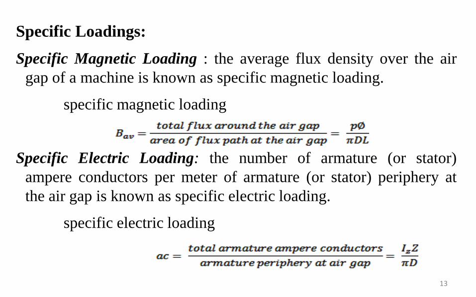
Specific Loadings:
Specific Magnetic Loading : the average flux density over the air
gap of a machine is known as specific magnetic loading.
specific magnetic loading
Specific Electric Loading: the number of armature (or stator)
ampere conductors per meter of armature (or stator) periphery at
the air gap is known as specific electric loading.
specific electric loading
13

Output Equation
Let
Vph = phase voltage ; Iph = phase current
Zph = no of conductors/phase; Tph = no of turns/phase
Ns = Synchronous speed in rpm; ns = synchronous speed in rps
p = no of poles ; ac = Specific electric loading
Ф= air gap flux/pole; Bav = Average flux density
Kw = winding factor ; η = efficiency
D = Diameter of the stator; L = Gross core length
Co = Output coefficient; cos υ = power factor
14

Consider an ‘m’ phase machine, with usual notations
Out put Q in kW = Input x efficiency
Input to motor = mVph Iph cosφ * 10-3 kW
For a 3 –υ machine m = 3
Input to motor = 3Vph Iph cosφ * 10-3 kW
Assuming Vph = Eph, Vph = Eph = 4.44 f Ф TphKw
= 2.22 f Ф ZphKw
f = PNS/120 = P* ns/2
15
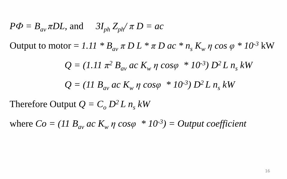
PФ = Bav πDL, and 3Iph Zph/ π D = ac
Output to motor = 1.11 * Bav π D L * π D ac * ns Kw η cos φ * 10-3 kW
Q = (1.11 π2 Bav ac Kw η cosφ * 10-3) D2 L ns kW
Q = (11 Bav ac Kw η cosφ * 10-3) D2 L ns kW
Therefore Output Q = Co D2 L ns kW
where Co = (11 Bav ac Kw η cosφ * 10-3) = Output coefficient
16
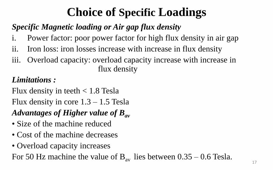
Specific Magnetic loading or Air gap flux density
i. Power factor: poor power factor for high flux density in air gap
ii. Iron loss: iron losses increase with increase in flux density
iii. Overload capacity: overload capacity increase with increase influx density
Limitations :
Flux density in teeth < 1.8 Tesla
Flux density in core 1.3 – 1.5 Tesla
Advantages of Higher value of Bav
• Size of the machine reduced
• Cost of the machine decreases
• Overload capacity increases
For 50 Hz machine the value of Bav lies between 0.35 – 0.6 Tesla.
Choice of Specific Loadings
17
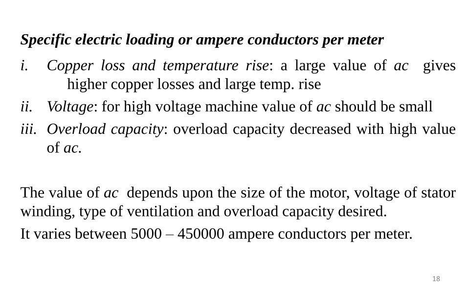
Specific electric loading or ampere conductors per meter
i. Copper loss and temperature rise: a large value of ac gives
higher copper losses and large temp. rise
ii. Voltage: for high voltage machine value of ac should be small
iii. Overload capacity: overload capacity decreased with high value
of ac.
The value of ac depends upon the size of the motor, voltage of stator
winding, type of ventilation and overload capacity desired.
It varies between 5000 – 450000 ampere conductors per meter.
18

Separation of D and L
The output equation gives the relation between D2L and output of the
machine. To separate D and L for this product a relation has to be
assumed. Following are the various design considerations based
on which a suitable ratio between gross length and pole pitch (L/τ)
assumed.
a) To obtain minimum over all cost 1.5 to 2.0
b) To obtain good efficiency 1.4 to 1.6
c) To obtain good over all design 1.0 to 1.1
d) To obtain good power factor 1.0 to 1.3
19

Power factor plays a very important role in the performance ofinduction motors. Hence to obtain the best power factor the followingrelation will be usually assumed for separation of D and L.
Pole pitch/ Core length = 0.18/pole pitch
or (πD/p) / L= 0.18/ (πD/p)
i.e D = 0.135P√L where D and L are in meter.
Peripheral Speed
The obtained values of D and L have to satisfy the conditionimposed on the value of peripheral speed.
For the normal design of induction motors the calculated diameter ofthe motor should be such that the peripheral speed must be below 30m/s. In case of specially designed rotor the peripheral speed can be60 m/s.
20

Stator slots: in general two types of stator slots are employed in inductionmotors viz, open slots and semi closed slots. Operating performance of theinduction motors depends upon the shape of the slots
(i) Open slots: In this type of slots the slot opening will be equal to that ofthe width of the slots. In such type of slots, assembly and repair of windingare easy. However such slots will lead to higher air gap contraction factorand hence poor power factor.
(ii) Semi closed slots: In such type of slots, slot opening is much smallerthan the width of the slot. Hence in this type of slots assembly of windingsis more difficult and takes more time compared to open slots and hence it iscostlier. However the air gap characteristics are better compared to opentype slots.
(iii) Tapered slots: In this type of slots also, opening will be much smallerthan the slot width. However the slot width will be varying from top of theslot to bottom of the slot with minimum width at the bottom.
Stator Design
21
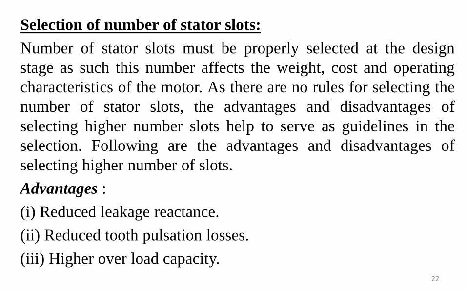
Selection of number of stator slots:
Number of stator slots must be properly selected at the design
stage as such this number affects the weight, cost and operating
characteristics of the motor. As there are no rules for selecting the
number of stator slots, the advantages and disadvantages of
selecting higher number slots help to serve as guidelines in the
selection. Following are the advantages and disadvantages of
selecting higher number of slots.
Advantages :
(i) Reduced leakage reactance.
(ii) Reduced tooth pulsation losses.
(iii) Higher over load capacity.22

Disadvantages:
(i) Increased cost
(ii) Increased weight
(iii) Increased magnetizing current
(iv) Increased iron losses
(v) Poor cooling
(vi) Increased temperature rise
(vii) Reduction in efficiency
The number of slots/pole/phase should not be less than 2 otherwise theleakage reactance becomes high. The number of slots should be selected togive an integral number of slots per pole per phase. The stator slot pitch atthe air gap surface should be between 1.5 to 2.5 cm.
Stator slot pitch at the air gap surface = τss= πD/Sss where Sss is the numberof stator slots
23
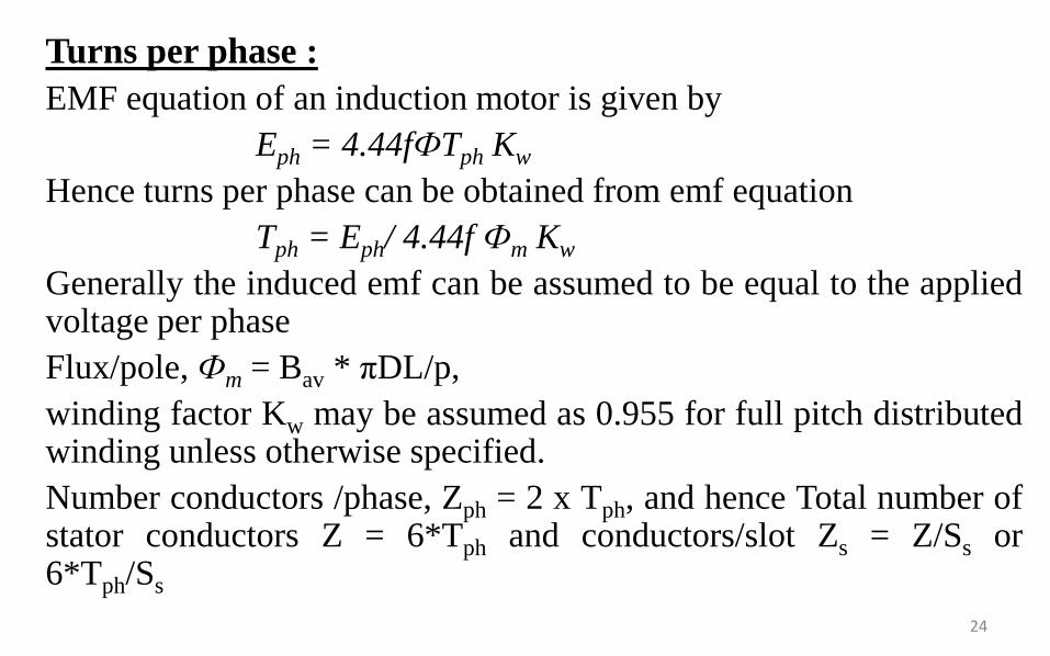
Turns per phase :
EMF equation of an induction motor is given by
Eph = 4.44fФTph Kw
Hence turns per phase can be obtained from emf equation
Tph = Eph/ 4.44f Фm Kw
Generally the induced emf can be assumed to be equal to the appliedvoltage per phase
Flux/pole, Фm = Bav * πDL/p,
winding factor Kw may be assumed as 0.955 for full pitch distributedwinding unless otherwise specified.
Number conductors /phase, Zph = 2 x Tph, and hence Total number ofstator conductors Z = 6*Tph and conductors/slot Zs = Z/Ss or6*Tph/Ss
24

Conductor cross section:
Area of cross section of stator conductors can be estimated from thestator current per phase and suitably assumed value of current densityfor the stator windings.
Sectional area of the stator conductor as = Is /δs where δs is thecurrent density in stator windings
Stator current per phase Is = Q / (3Vph cosυ)
A suitable value of current density has to be assumed considering theadvantages and disadvantages.
Advantages of higher value of current density:
(i) reduction in cross section
(ii) reduction in weight
(iii) reduction in cost
25

Disadvantages of higher value of current density:
(i) increase in resistance
(ii) increase in cu loss
(iii) increase in temperature rise
(iv) reduction in efficiency
Higher value is assumed for low voltage machines and smallmachines. Usual value of current density for stator windings is 3 to 5amps/mm2.
Area of stator slot: Slot area is occupied by the conductors and theinsulation. Out of which almost more than 25 % is the insulation.Once the number of conductors per slot is decided, approximate areaof the slot can be estimated.
Slot space factor = Copper area in the slot /Area of each slot
This slot space factor so obtained will be between 0.25 and 0.4.26
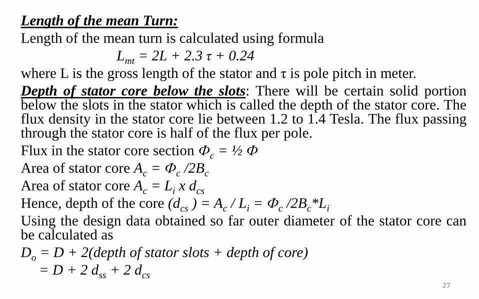
Length of the mean Turn:
Length of the mean turn is calculated using formula
Lmt = 2L + 2.3 τ + 0.24
where L is the gross length of the stator and τ is pole pitch in meter.
Depth of stator core below the slots: There will be certain solid portionbelow the slots in the stator which is called the depth of the stator core. Theflux density in the stator core lie between 1.2 to 1.4 Tesla. The flux passingthrough the stator core is half of the flux per pole.
Flux in the stator core section Фc = ½ Ф
Area of stator core Ac = Фc /2Bc
Area of stator core Ac = Li x dcs
Hence, depth of the core (dcs ) = Ac / Li = Фc /2Bc*Li
Using the design data obtained so far outer diameter of the stator core canbe calculated as
Do = D + 2(depth of stator slots + depth of core)
= D + 2 dss + 2 dcs27

There are two types of rotor construction. One is the squirrel cage rotor and
the other is the slip ring rotor. Most of the induction motor are squirrel cage
type. These are having the advantage of rugged and simple in construction
and comparatively cheaper. However they have the disadvantage of lower
starting torque. In this type, the rotor consists of bars of copper or
aluminium accommodated in rotor slots. In case slip ring induction motors
the rotor complex in construction and costlier with the advantage that they
have the better starting torque. This type of rotor consists of star connected
distributed three phase windings.
Rotor Design
28

Between stator and rotor is the air gap which is a very critical part.The performance parameters of the motor like magnetizing current,power factor, over load capacity, cooling and noise are affected bylength of the air gap.
Power Factor:- the mmf required to send the flux through air gap isproportional to the product of flux density and length of air gap.
fig shows phasor diagrams of an induction motor with two differentair gap lengths. With increase in air gap length, magnetizing mmfincreases and hence greater themagnetizing current. Therefore, thephase angle between applied voltageand stator current will increase whichgives low power factor.
Length of Air-gap
29
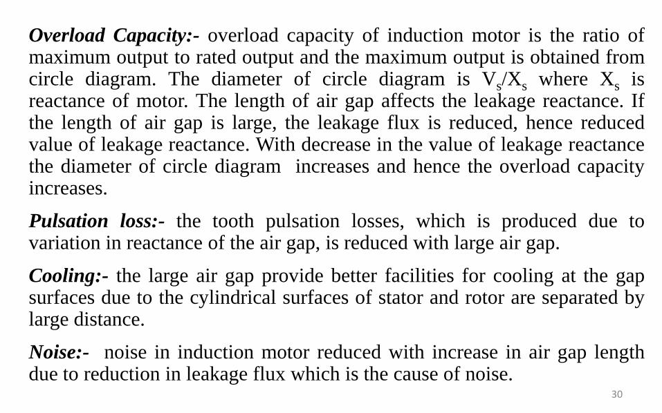
Overload Capacity:- overload capacity of induction motor is the ratio ofmaximum output to rated output and the maximum output is obtained fromcircle diagram. The diameter of circle diagram is Vs/Xs where Xs isreactance of motor. The length of air gap affects the leakage reactance. Ifthe length of air gap is large, the leakage flux is reduced, hence reducedvalue of leakage reactance. With decrease in the value of leakage reactancethe diameter of circle diagram increases and hence the overload capacityincreases.
Pulsation loss:- the tooth pulsation losses, which is produced due tovariation in reactance of the air gap, is reduced with large air gap.
Cooling:- the large air gap provide better facilities for cooling at the gapsurfaces due to the cylindrical surfaces of stator and rotor are separated bylarge distance.
Noise:- noise in induction motor reduced with increase in air gap lengthdue to reduction in leakage flux which is the cause of noise.
30

Hence length of the air gap is selected considering the advantages anddisadvantages of larger air gap length.Advantages:
(i) Increased overload capacity(ii) Increased cooling(iii) Reduced unbalanced magnetic pull(iv) Reduced in tooth pulsation(v) Reduced noise
Disadvantages(i) Increased Magnetising current(ii) Reduced power factor
Magnetising current and power factor being very important parameters indeciding the performance of induction motors, the induction motors aredesigned for optimum value of air gap or minimum air gap possible. Hencein designing the length of the air gap following empirical formula isemployed.Air gap length lg = 0.2 + 2√DL mm
31
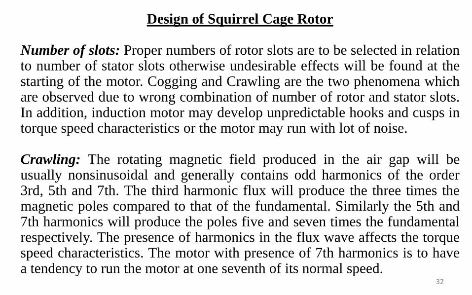
Design of Squirrel Cage Rotor
Number of slots: Proper numbers of rotor slots are to be selected in relationto number of stator slots otherwise undesirable effects will be found at thestarting of the motor. Cogging and Crawling are the two phenomena whichare observed due to wrong combination of number of rotor and stator slots.In addition, induction motor may develop unpredictable hooks and cusps intorque speed characteristics or the motor may run with lot of noise.
Crawling: The rotating magnetic field produced in the air gap will beusually nonsinusoidal and generally contains odd harmonics of the order3rd, 5th and 7th. The third harmonic flux will produce the three times themagnetic poles compared to that of the fundamental. Similarly the 5th and7th harmonics will produce the poles five and seven times the fundamentalrespectively. The presence of harmonics in the flux wave affects the torquespeed characteristics. The motor with presence of 7th harmonics is to havea tendency to run the motor at one seventh of its normal speed.
32

Cogging: In some cases where in the number of rotor slots are notproper in relation to number of stator slots the machine refuses torun and remains stationary. Under such conditions there will be alocking tendency between the rotor and stator. Such a phenomenonis called cogging.Hence in order to avoid such bad effects a proper number of rotorslots are to be selected in relation to number of stator slots. Inaddition rotor slots will be skewed by one slot pitch to minimize thetendency of cogging, torque defects like synchronous hooks andcusps and noisy operation while running. Effect of skewing willslightly increase the rotor resistance and increases the startingtorque. However this will increase the leakage reactance and hencereduces the starting current and power factor.
33

Selection of number of rotor slots: The number of rotor slots may be selected
using the following guide lines.
(i) To avoid cogging and crawling: (a)Ss ≠ Sr (b) Ss - Sr ≠ 3P
(ii) To avoid synchronous hooks and cusps in torque speed characteristics Ss - Sr
≠ P, 2P, 5P.
(iii) To noisy operation Ss - Sr ≠ 1, 2, (P ±1), (P ±2)
Rotor Bar Current: Bar current in the rotor of a squirrel cage induction motor
may be determined by comparing the mmf developed in rotor and stator. The
stator mmf is about 15% higher because of the magnetizing mmf.
Rotor mmf = 0.85 (stator mmf)
Number of rotor bars = Nb = Sr = number of rotor slots
Rotor bar current = Ib
Rotor mmf = Ib. Sr/2
Stator mmf = 3. Is . Ts
Thus Ib.Sr/2 = 0.85 (3. Is . Ts) or Ib = 0.85 * (6*Is*Ts/Sr)34

Cross sectional area of Rotor bar: Sectional area of the rotor conductor can becalculated by rotor bar current and assumed value of current density for rotorbars. As a guide line the rotor bar current density can be assumed between 4 to 7Amp/mm2 .Hence sectional area of the rotor bars can be calculated as
Ab = Ib /δb mm2
Shape and Size of the Rotor slots: Generally semi-closed slots or closed slotswith very small or narrow openings are employed for the rotor slots. In case offully closed slots the rotor bars are force fit into the slots from the sides of therotor.The rotors with closed slots are giving performance to the motor in thefollowing way. (i) As the rotor slot is closed the rotor surface is smooth at the airgap and hence the motor draws lower magnetizing current. (ii) reduced noise asthe air gap characteristics are better (iii) increased leakage reactance and (iv)reduced starting current. (v) Over load capacity is reduced (vi) Undesirable andcomplex air gap characteristics. From the above it can be concluded that semi-closed slots are more suitable and hence are employed in rotors.
35

Copper loss in rotor bars: Knowing the length of the rotor bars andresistance of the rotor bars cu losses in the rotor bars can be calculated.Length of rotor bar lb = L + allowance for skewingRotor bar resistance = 0.021 x lb / Ab
Copper loss in rotor bars = Ib2 x rb x number of rotor bars.
End Ring Current: All the rotor bars are short circuited by connectingthem to the end rings at both the end rings. As the rotor is a shortcircuited, there will be current flow because of induced emf in the rotorbars. The distribution of current and end rings are as shown in Fig.Considering the bars under one pole pitch, half of the number of bars andthe end ring carry the current in one direction and the other half in theopposite direction. Thus the maximum end ring current may be taken asthe sum of the average current in half of the number of bars under onepole.
36
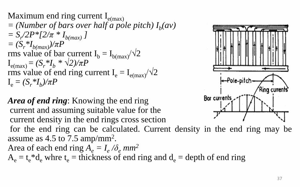
Maximum end ring current Ie(max)
= (Number of bars over half a pole pitch) Ib(av)= Sr/2P*[2/π * Ib(max) ]= (Sr*Ib(max))/πPrms value of bar current Ib = Ib(max)/√2Ie(max) = (Sr*Ib * √2)/πPrms value of end ring current Ie = Ie(max)/√2Ie = (Sr*Ib)/πP
Area of end ring: Knowing the end ringcurrent and assuming suitable value for thecurrent density in the end rings cross sectionfor the end ring can be calculated. Current density in the end ring may beassume as 4.5 to 7.5 amp/mm2.Area of each end ring Ae = Ie /δe mm2
Ae = te*de whre te = thickness of end ring and de = depth of end ring
37
Design of wound Rotor
These are the types of induction motors where in rotor also carriesdistributed star connected 3 phase winding. At one end of the rotorthere are three slip rings mounted on the shaft. Three ends of thewinding are connected to the slip rings. External resistances can beconnected to these slip rings at starting, which will be inserted in serieswith the windings which will help in increasing the torque at starting.Such type of induction motors are employed where high starting torqueis required.
Number of rotor slots: The number of rotor slots should never be equalto number of stator slots. Generally for wound rotor motors a suitablevalue is assumed for number of rotor slots per pole per phase, and thentotal number of rotor slots are calculated. So selected number of slotsshould be such that tooth width must satisfy the flux density limitation.Semi-closed slots are used for rotor slots.
38
Number of rotor Turns: The voltage between the slip rings on open
circuit must be limited to safety values. In general the voltage between
the slip rings for low and medium voltage machines must be limited to
400 volts. For motors with higher voltage ratings and large size motors
this voltage must be limited to 1000 volts. Based on the assumed
voltage between the slip rings comparing the induced voltage ratio in
stator and rotor, the number of turns on rotor winding can be calculated.
Voltage ratio Er/ Es = (Kwr x Tr) / (Kws x Ts )
Hence rotor turns per phase Tr = (Er/Es) (Kws/Kwr)Ts
Er = open circuit rotor voltage/phase
Es = stator voltage /phase
Kws = winding factor for stator
Kwr = winding factor for rotor
Ts = Number of stator turns/phase39
Rotor Current and conductor section
Assuming rotor mmf = 0.85* stator mmf
2x3xIr.Tr = (0.85) 2x3xIs.Ts
Rotor current per phase Ir = (0.85) Is.Ts/T
Rotor conductor area Ar = Ir/δr
The current density could be taken as 3 to 5 A/mm2
40
No load current: The no load current of an induction motor has two
components magnetizing component, Im and iron loss component, Iw.
Thus the no load current I0 = √(Im)2 + (Iw)2 amps
Magnetising current: Magnetising current of an induction motor is
responsible for producing the required amount of flux in the different
parts of the machine. Hence this current can be calculated from all the
magnetic circuit of the machine. The ampere turns for all the magnetic
circuit such as stator core, stator teeth, air gap, rotor core and rotor
teeth gives the total ampere turns required for the magnetic circuit.
Based on the total ampere turns of the magnetic circuit the magnetizing
current can be calculated as
41

Magnetising current Im= P*AT60 / (2.34 kw Tph )
where p – no of pairs of poles, AT30 – Total ampere turns of themagnetic circuit at 600 from the centre of the pole, Tph – Number ofstator turns per phase.
Iron loss component of current: This component of current is responsiblefor supplying the iron losses in the magnetic circuit. Hence thiscomponent can be calculated from no load losses and applied voltage.
Iron loss component of current Iw= Total no load losses / ( 3 xphase voltage)
No load Power Factor: No load power factor of an induction motor isvery poor. As the load on the machine increases the power factorimproves. No load power factor can be calculated knowing thecomponents of no load current.
No load power factor cosυ0 = Iw / I0
42
Dispersion Coefficient:
Power factor is an important factor in designing of induction motor.Power factor depends upon two factors:
i) Magnetizing current :a large value of the magnetizing currentindicates poor power factor
ii) Ideal short circuit current (Isc): it is defined as the current drawnby the motor at standstill neglecting its resistance. A large valueof ideal short circuit current will be drawn for small value ofleakage reactance giving good power factor.
Dispersion coefficient defined as the ratio of magnetizing current toideal short circuit current.
Thus dispersion coefficient, σ = Im/Isci
=Im/(Es/Xs) Isci = Es/Xs
=Im.Xs/Es43

For small values of Im and Xs dispersion coefficient is small and
power factor is good. Thus for a small value of dispersion
coefficient power factor is good, where as for large value of
dispersion coefficient power factor is poor.
Magnetizing current Im = P*AT60 / (2.34 kw Tph )
Where AT60 is the total mmf consumed by flux path, out of which a
large part is consumed by air gap length.
AT air gap = 800000* 1.36* Bav l’g
Im α P * Bav l’g / Kws. Ts
Isci = Es/Xs
44

From equation , machine a given L and D, the dispersion coefficientis large for grater number of poles, consequently making powerfactor poor. Thud slow speed machine have poor power factor.
Effect of dispersion coefficient on induction motor characteristics:
1. Effect on maximum power factor:
As shown in circle diagram
OA=magnetizing current
OB=ideal short circuit current
Dispersion coefficient:
σ = OA/OB
For maximum power factor OD is tangent to the circle and
∟ODC =90o45

For σ = 0.05, maximum p.f. = 0.905
For σ = 0.10, maximum p.f. = 0.818
Hence there is a large decrease in maximum p.f. when the dispersioncoefficient increases.
2. Effect on overload capacity:
Assuming, an induction motor is designed to have maximum pf at full load, its corresponding output will be DE. The maximum output will becorresponding to FC
For σ = 0.05 overload capacity = 2.348
For σ = 0.10 overload capacity = 1.740
Hence overload capacity decreases with increase in dispersion coeff.
46


