46 IEEE TRANSACTIONS ON BROADCASTING, VOL. 36, NO. 1, MARCH 1990 DESIGN OF TUBE POWER AMPLIFIERS FOR OPTIMUM FM TRANSMITTER PERFORMANCE Mukunda B. Shrestha Manager of RF Engineering Broadcast Electronics, Inc. 4100 North 24th Street P.O. Box 3606 Quincy, I L 62305 ABSTRACT Tube amplifiers are extensively used in modern high power FM broadcast transmitters. The power amplifier bandwidth affects not only the modulation performance but also the transmitter's immunity to RF intermodulation. involved are discussed with recommendations on the choice o f bandwidth. The design of tube power ampli- fiers for optimum FM performance requires careful considerations i n the selection (of input matching and output coupling circuit topologies due to their effects on the transmitter amplitude and group delay responses. Results of computer {circuit analysis and measured amplitude and group delay responses are com- pared for different circuit topologies. performance data of a typical 20 kW FM transmitter is also presented to illustrate the effects of tube power amplifier input and output circuits. The trade-offs Modulation INTRODUCTION Tube amplifiers are widely used in freq- uency modulation (FM) broadcast transmitters to in- crease the level of the FM signal at the wideband exciter or Intermediate Power Amplifier (IPA) output to higher power output levels. Tube amplifiers are more efficient and cost effective at high power levels than a combination of several low power solid- state amplifiers in the 88-108 MHz FM broadcast band. The power amplifier (PA) is typically a high gain single-tube type operated as a tuned class "C" radio frequency (RF) amplifier. The PA design goal i s to deliver the authorized power output to the antenna with high efficiency and reliability while providing excellent modulation performance. This paper discusses various topologies of the input and output circuits of a vacuum tube power amplifier and analyzes their effects on the trans- mitter amplitude and group delay responses. Results of computer circuit analysis and actual measured data of a typical transmitter with two different topol- ogies are compared. Design considerations for opti- mum transmitter performance to ac:hieve desired level of transparency to a wideband FM broadcast signal i s also discussed including recommendations for compen- sating the group delay of the transmission system. The contents of the paper are divided into the fol- lowing main headings: Of Bandwidth Limitation On The Transmitter Per- formance. 1. Frequency Modulated Signal And Effects 2. Power Amplifier Design Considerations. - Primary Design Factors. - Input Circuit Configurations And Their Effects On The Transmitter Bandwidth. - Output Circuit Configurations And Their Effects On The Transmitter Bandwidth. - Computed/Measured Amplitude And Group Delay Responses. Modulation Performance Of A Typical 20 kW Single-Tube FM Transmitter. 3. FREQUENCY MODULATED SIGNAL AND EFFECTS OF BANDWIDTH LIMITATION ON THE TRANSMITTER PERFORMANCE Frequency Modulated Signal A Frequency Modulated RF Signal with modu- lation index "m", carrier frequency "fc", and single- tone modulation frequency "fm" can be represented by the following mathematical expression [l-61: E(t) = Ec.Cos[wc-t + m-Sin(wm-t)], Where: Ec = The unmodulated carrier amplitude DC = 2-ir-fc (carrier frequency) wm = 2a-fm (modulating frequency) m =Af/fm = frequency deviation/modulating constant frequency In an FM signal, the deviation 'af" of the instantaneous frequency from the average (or the carrier frequency) is directly proportional to the instantaneous amplitude of the modulating signal. The rate of frequency deviation i s the modulating signal frequency, infinite series of discrete spectral components using trigonometric expansions and series representations of Bessel functions [l-51. E(t) = Ec.3 The above FM Signal can be expressed as an Jn(m).Cos[(uc + n.om)-t], n=-m Where Jn(m) are Bessel functions of the first kind and nth order with argument "m". The numeric values of the Bessel functions Jn(m) for different "n" express the amp1 i tudes of the various frequency components relative to the unmodulated car- rier amplitude. argument "m" and the order "n". These can be found from the mathematical tables. The values of Jn(m) depend on the For example: If n = 0, Jn(m) = Jo(m), which i s the ampli- tude of the carrier component. If n = +1, Jn(m) = Jl(m) and J-l(m), which are the amplitudes of the first order side- band components. If n = ?2, Jn(m) = J2(m) and J-2(m), which are the amplitudes of the second order sideband components. 0018-9316/90/0300-0046$01.00 0 1990 IEEE
Transcript
46 IEEE T R A N S A C T I O N S ON B R O A D C A S T I N G , VOL. 36, NO. 1 , MARCH 1990
DESIGN OF TUBE POWER AMPLIFIERS FOR OPTIMUM FM TRANSMITTER PERFORMANCE
Mukunda B. Shrestha Manager o f RF Eng ineer ing
Broadcast E l e c t r o n i c s , I nc . 4100 Nor th 24 th S t r e e t
P.O. Box 3606 Quincy, I L 62305
ABSTRACT
Tube a m p l i f i e r s a r e e x t e n s i v e l y used i n modern h i g h power FM b roadcas t t r a n s m i t t e r s . The power a m p l i f i e r bandwidth a f f e c t s n o t o n l y t h e modu la t i on performance b u t a l s o t h e t r a n s m i t t e r ' s immunity t o RF i n t e r m o d u l a t i o n . i n v o l v e d a r e d i scussed w i th recommendations on t h e cho ice o f bandwidth. The des ign o f tube power amp l i - f i e r s f o r optimum FM performance r e q u i r e s c a r e f u l c o n s i d e r a t i o n s i n t h e s e l e c t i o n (of i n p u t match ing and o u t p u t c o u p l i n g c i r c u i t t o p o l o g i e s due t o t h e i r e f f e c t s on t h e t r a n s m i t t e r amp l i t ude and group de lay responses. Resu l t s o f computer { c i r c u i t a n a l y s i s and measured amp l i t ude and group de lay responses a re com- pared f o r d i f f e r e n t c i r c u i t t o p o l o g i e s . performance da ta o f a t y p i c a l 20 kW FM t r a n s m i t t e r i s a l s o presented t o i l l u s t r a t e t h e e f f e c t s o f tube power a m p l i f i e r i n p u t and o u t p u t c i r c u i t s .
The t r a d e - o f f s
Modu la t i on
INTRODUCTION
Tube a m p l i f i e r s a r e w i d e l y used i n f r e q - uency modu la t i on (FM) broadcast t r a n s m i t t e r s t o i n - crease t h e l e v e l o f t h e FM s i g n a l a t t h e wideband e x c i t e r o r I n te rmed ia te Power A m p l i f i e r ( IPA) o u t p u t t o h i g h e r power o u t p u t l e v e l s . Tube a m p l i f i e r s a r e more e f f i c i e n t and c o s t e f f e c t i v e a t h i g h power l e v e l s than a combinat ion o f seve ra l low power s o l i d - s t a t e a m p l i f i e r s i n t h e 88-108 MHz FM b roadcas t band.
The power a m p l i f i e r (PA) i s t y p i c a l l y a h i g h g a i n s i n g l e - t u b e t y p e opera ted as a tuned c l a s s " C " r a d i o f requency (RF) a m p l i f i e r . The PA des ign goal i s t o d e l i v e r t h e a u t h o r i z e d power o u t p u t t o t h e antenna w i t h h i g h e f f i c i e n c y and r e l i a b i l i t y w h i l e p r o v i d i n g e x c e l l e n t modu la t i on performance.
Th is paper d iscusses v a r i o u s t o p o l o g i e s o f t h e i n p u t and o u t p u t c i r c u i t s o f a vacuum tube power a m p l i f i e r and analyzes t h e i r e f f e c t s on t h e t r a n s - m i t t e r amp l i t ude and group de lay responses. Resu l t s o f computer c i r c u i t a n a l y s i s and a c t u a l measured da ta o f a t y p i c a l t r a n s m i t t e r w i t h two d i f f e r e n t t o p o l - og ies a r e compared. Design c o n s i d e r a t i o n s f o r o p t i - mum t r a n s m i t t e r performance t o ac:hieve d e s i r e d l e v e l o f t ransparency t o a wideband FM b roadcas t s i g n a l i s a l s o d iscussed i n c l u d i n g recommendations f o r compen- s a t i n g t h e group de lay o f t h e t ransmiss ion system. The con ten ts o f t h e paper a r e d i v i d e d i n t o t h e f o l - l ow ing main headings:
O f Bandwidth L i m i t a t i o n On The T r a n s m i t t e r Per- formance.
1. Frequency Modulated S igna l And E f f e c t s
2. Power A m p l i f i e r Design Considerat ions. - Pr imary Design Fac to rs . - I n p u t C i r c u i t C o n f i g u r a t i o n s And
T h e i r E f f e c t s On The T r a n s m i t t e r Bandwidth.
- Output C i r c u i t Con f igu ra t i ons And T h e i r E f f e c t s On The T r a n s m i t t e r Bandwidth.
- Computed/Measured Ampl i tude And Group Delay Responses.
Modu la t i on Performance O f A T y p i c a l 20 kW Single-Tube FM T r a n s m i t t e r .
3.
FREQUENCY MODULATED SIGNAL AND EFFECTS OF BANDWIDTH LIMITATION ON THE TRANSMITTER PERFORMANCE
Frequency Modulated S igna l
A Frequency Modulated RF S igna l w i t h modu- l a t i o n i ndex "m", c a r r i e r f requency " f c " , and s i n g l e - tone modu la t i on f requency " f m " can be rep resen ted by t h e f o l l o w i n g mathemat ica l exp ress ion [ l - 61 :
E ( t ) = Ec.Cos[wc-t + m-Sin(wm-t ) ] ,
Where:
Ec = The unmodulated c a r r i e r amp l i t ude
DC = 2-ir-fc ( c a r r i e r f requency) w m = 2a - fm (modulat ing f requency)
m =Af/fm = f requency dev ia t i on /modu la t i ng
cons tan t
f requency
I n an FM s i g n a l , t h e d e v i a t i o n 'af" o f t h e instantaneous f requency f rom t h e average ( o r t h e c a r r i e r frequency) i s d i r e c t l y p r o p o r t i o n a l t o t h e instantaneous amp l i t ude o f t he modu la t i ng s i g n a l . The r a t e o f f requency d e v i a t i o n i s t h e modu la t i ng s i g n a l f requency,
i n f i n i t e s e r i e s o f d i s c r e t e s p e c t r a l components u s i n g t r i g o n o m e t r i c expansions and s e r i e s r e p r e s e n t a t i o n s o f Bessel f u n c t i o n s [l-51.
E ( t ) = E c . 3
The above FM Signa l can be expressed as an
Jn(m).Cos[(uc + n .om) - t ] , n = - m
Where Jn(m) a r e Bessel f u n c t i o n s o f t h e f i r s t k i n d and n t h o rde r w i t h argument "m". The numeric va lues o f t h e Bessel f u n c t i o n s Jn(m) f o r d i f f e r e n t "n" express t h e amp1 i tudes o f t h e va r ious frequency components r e l a t i v e t o t h e unmodulated c a r - r i e r ampl i tude. argument "m" and t h e o r d e r "n". These can be found f rom t h e mathemat ica l t a b l e s .
The va lues o f Jn(m) depend on t h e
For example:
If n = 0, Jn(m) = Jo(m), which i s t h e ampl i - t ude o f t h e c a r r i e r component.
If n = +1, Jn(m) = J l (m) and J - l (m) , which a r e t h e ampl i tudes o f t h e f i r s t o rde r s ide - band components.
I f n = ?2, Jn(m) = J2(m) and J-2(m), which a r e t h e ampl i tudes o f t h e second o rde r sideband components.
0018-9316/90/0300-0046$01.00 0 1990 IEEE
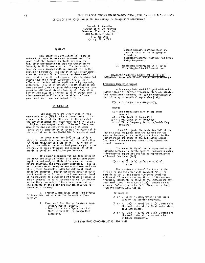
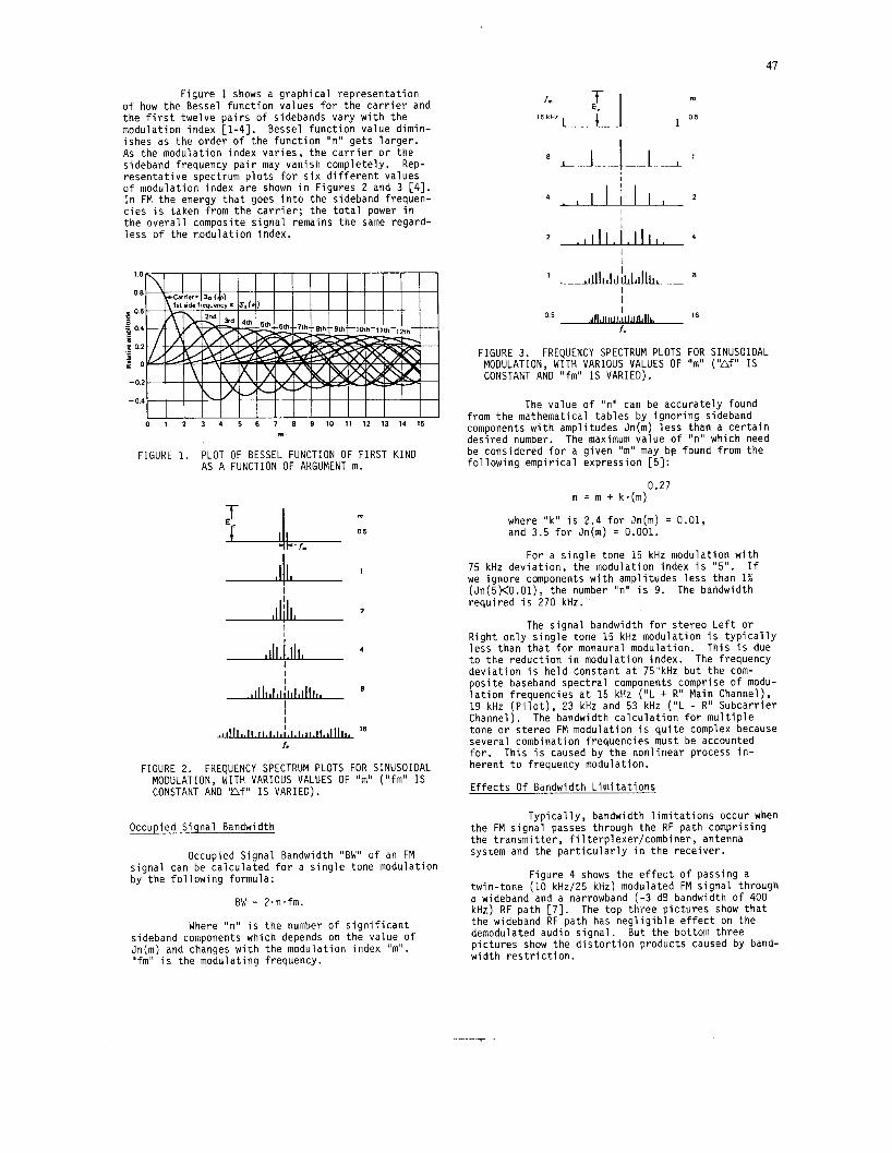
F i g u r e 1 shows a g r a p h i c a l r e p r e s e n t a t i o n o f how t h e Bessel f u n c t i o n va lues f o r t h e c a r r i e r and t h e f i r s t twe lve p a i r s o f sidebands v a r y w i t h t h e modu la t i on i ndex [ l - 41 . Bessel f u n c t i o n va lue d im in - i shes as t h e o r d e r o f t h e f u n c t i o n "n" ge ts l a r g e r . As t h e modu la t i on i ndex v a r i e s , t h e c a r r i e r o r t h e sideband f requency p a i r may van ish complete ly . r e s e n t a t i v e spectrum p l o t s f o r s i x d i f f e r e n t va lues o f modu la t i on i ndex a r e shown i n F igu res 2 and 3 [4]. I n FM t h e energy t h a t goes i n t o t h e sideband f requen- c i e s i s t aken f rom t h e c a r r i e r ; t h e t o t a l power i n t h e o v e r a l l composite s i g n a l remains t h e same regard - l e s s o f t h e modu la t i on index.
Rep-
4 3 1
1 0
0 8
0 6
g o 4
5 5 02
P O -
- 0 2
- 0 4
0 1 2 3 4 5 E 7 8 9 1 0 1 1 1 2 1 3 1 4 1 5
2 I I ,
m
FIGURE 1. PLOT OF BESSEL FUNCTION OF FIRST K I N D AS A FUNCTION OF ARGUMENT m.
I
.llljlll-- I
A4 - I I
I t ,lllllljlllllll 8
I I I
IC
16
FIGURE 2. FREQUENCY SPECTRUM PLOTS FOR SINUSOIDAL MODULATION, WITH VARIOUS VALUES OF "m" ( " fm" I S CONSTANT AND 'Af" I S VARIED).
Occupied S igna l Bandwidth
Occupied S igna l Bandwidth "BW" o f an FM s i g n a l can be c a l c u l a t e d f o r a s i n g l e tone modu la t i on by t h e f o l l o w i n g formula:
BW = 2-n.fm.
Where "n" i s t h e number o f s i g n i f i c a n t sideband components which depends on t h e va lue of Jn(m) and changes w i t h t h e modu la t i on i ndex "m". " f m " i s t h e modu la t i ng f requency.
16 kHz 0 5
. , I ~ I , / , I ~ I , . I I
1 8 I .
I I
fc
0.5 AilA#,,, 16
FIGURE 3. FREQUENCY SPECTRUM PLOTS FOR SINUSOIDAL MODULATIONy WITH VARIOUS VALUES OF I'm" ( "A f ' ' IS CONSTANT AND " f m " I S VARIED).
The va lue o f 'In" can be a c c u r a t e l y found f rom t h e mathemat ica l t a b l e s by i g n o r i n g sideband components w i t h ampl i tudes Jn(m) l e s s than a c e r t a i n d e s i r e d number. The maximum va lue o f "n" which need be considered f o r a g i v e n "m" may bp found f rom t h e f o l l o w i n g e m p i r i c a l exp ress ion [5]:
0.27 n = m + k- (m)
where "k" i s 2.4 f o r Jn(m) = 0.01, and 3.5 f o r Jn(m) = 0.001.
For a s i n g l e tone 15 kHz modu la t i on w i t h 75 kHz d e v i a t i o n , t h e modu la t i on index i s "5" . I f we i g n o r e components w i t h ampl i tudes l e s s than 1% (Jn(5)<0.01), t h e number "n" i s 9. The bandwidth r e q u i r e d i s 270 kHz.
The s i g n a l bandwidth f o r s t e r e o L e f t o r R i g h t o n l y s i n g l e tone 15 kHz modu la t i on i s t y p i c a l l y l e s s than t h a t f o r monaural modu la t i on . T h i s i s due t o t h e r e d u c t i o n i n modu la t i on index. The f requency d e v i a t i o n i s h e l d cons tan t a t 75 ' kHr b u t t h e com- p o s i t e baseband s p e c t r a l components comprise o f modu- l a t i o n f requenc ies a t 15 kHz ( " L + R" Main Channel), 19 kHz ( P i l o t ) , 23 kHz and 53 kHz ( " L - R " S u b c a r r i e r Channel). The bandwidth c a l c u l a t i o n f o r m u l t i p l e tone o r s t e r e o FM modu la t i on i s q u i t e complex because seve ra l combinat ion f requenc ies must be accounted f o r . Th i s i s caused by t h e n o n l i n e a r process i n - he ren t t o f requency modulat ion.
E f f e c t s O f Bandwidth L i m i t a t i o n s
T y p i c a l l y , bandwidth l i m i t a t i o n s occur when t h e FM s i g n a l passes th rough t h e RF p a t h compr i s ing t h e t r a n s m i t t e r , f i l t e r p l e x e r / c o m b i n e r , antenna system and t h e p a r t i c u l a r l y i n t h e r e c e i v e r .
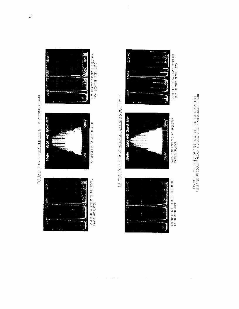
tw in - tone (10 kHz/25 kHz) modulated FM s i g n a l t h rough a wideband and a narrowband ( - 3 dB bandwidth o f 400 kHz) RF p a t h [7]. The t o p thi-ee p i c t u r e s show t h a t t h e wideband RF p a t h has n e g l i g i b l e e f f e c t on t h e demodulated aud io s i g n a l . p i c t u r e s show t h e d i s t o r t i o n p roduc ts caused by band- w i d t h r e s t r i c t i o n .
F i g u r e 4 shows t h e e f f e c t o f pass ing a
But t h e bot tom t h r e e
..* -
48
PI
49
Stereophonic THD+N At 15 kHz Versus Bandwidth
% THD
i
0 4 0 6 0 8 1 1 5 2
O O l L 1- 1- I I I
Bandwidth (MHz)
3
Composi te THD+N A t 15 kHz Versus Bandwid th
Yo THD
Stereophon ic SMPTE IMD (60Hz I7kHz 4:l Ratio) Versus Bandwidth
Yo IMD
O l r i n--- I I
3
O.O5,',! 0.02
3
Composi te SMPTE IMD (60Hz/7kHz 1:l Rat io) Versus Bandwidth
% IMD
S t e r e o Separa t ion Versus Bandwid th
dB 3
?l$EE$= -60
-70 L i - I I 1 0 4 0 6 0 8 1 1 5 2
Bandwidth (MHz)
3
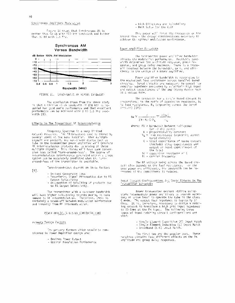
50
Synchronous AM Versus Bandwidth
dB Below 100% AM Modulation
-1: --- -20
:E ;;=, -60 -70
0.4 0.6 0.8 1 1.5 2 3
Bandwidth (MHz)
FIGURE !C. SYhCHPOi.,(!I'C P Y ilEPSLiS CFI?~LJ~YIDTII
The ccnc lus ion drawn froni ti;e above stuc'y i s t h i t a n:inimum -2 cH bandwidth c f 800 k i j ? 1 5 r e - quired f u r jood audic pcrforrr,ance a n d t h a t exce l i i . n t pt>rformancc Lan be ac!iisved with 1 t ? i . 5 Mhz bond- w d t h [S I .
t t f e c t s G n The TransiTi t ter R F interircdu1dt:on
Frequer.cj Spectruii: i z a very l i m i t e d n a t J r d l r e source . The FM bi-oddcds: b j i 16 i c shared tjj, seve ra l userr. 2: t h e saiw i o c a t i o n . b!hen m u l t i p l e s i g n a l s d re p r e s e n t , 21,y tion-lir,ear dev ice :uch d s tube i n t h e t r a n m i t t e r p o k e r dmpl i t i e r wi 1 1 g?r!ei-dte F F interriioc;ulatiot: prcducts dur to n,ixing o f t h e s e m u l t i p l e s i g n a l s . T h j s niixina w i l l hdke s o w conver- s ion l o s s c i l l led " turn-at .ouna-lois" . The degr;t of i r i teraodul i l t ion i n t e r f e r e n c e generated wi th in c given system cdn t e a c c u r a t e l y p red ic t56 i~i-,eti t h e '-urn- zrcund-loss c i f the t r a n x i t t e r i s a v a i l a b l e .
Turn-Arourtd-Loss ciepinds on t h r e e f a c t o r s
- I n - b a n d Conversior L o s s - Ititerferiric, Signal Attet iuat ion due t c PA
- Attenuat ion of Resul t ing iK products due
[9!.
O u t p u t S e l e c t i v i t y
t o P A C u t p u t S e l e c z i v i t y .
The t r a n s m i t t e r with a r,ilrrow?r bandwidth w i l l have higher s e l e c t i v i t y t t e r e b y maki!iQ i t m r e immune t o F t l i n t e rmodu la t ion . T h e w f o r e , t h e r e i s c e r t a i n l y 2 t r i lae-off between modu!dtion performance arid immunity from RF interniodu.ldtion.
'iriinary Desiry F a i i o r s
The prirdary f a c t o r s b(tiich shouib tJr con-
- Crs i r ed Powtr O u t p c t - Optimur: l'oGuiatiorl Performarce
s i d e r e d i n Power Amplif ier c e s i a n d re :
T h i : p a p e r wii ' f ccus i t s d i scus j io r i or, tt-e second i t,t:rl - t h e i e s i l j i i c o n s i d e r c t i o n s nec r s sa ry t o d :. I I i e v e t h i~ o p t i mum no dd 1 3 t I CI n p e I' f o rim nce .
The l.i-;.rcmitt.t>r power. m p l i f i r r handwiclih ( i f f e c t s t h e ii:odulat;r,ii perforiiiai-,cF. Availzt1:t: baiid-
sponsc:, 2nd group d r l a y resy.ottre. There i: ct t r s d e - o f f jiivolved b e t w e n t h e bdqdwidth, (JdiK: apd e f t i - cier.cy i n t h e c ie5 iq t i of a power c inp l i f i e r .
e s t h e amp1 i tudp resp.,ribt., phs5+ ',-c-
P o w r u ~ , p l i f i t : r bardwidth i: r e s t r i c t e c , by the equiva ' ,ent 1oOc r e s i s t a n c e ;icross p a r a l l e l t u n P d c i w u i t s . Tuned c i r c u i t s i ~ r e necess,ir:. t o cancel l o w r e a c t i v e 1i::pt'dance preier i ted by r c l a t ive l .8 hisii - i n p u t i , r d ou tpu t cdpacit;ricej cf t h e amp1:i'yiny device such <:s d vacu~i;i t i ibe.
T h P baiidwi(!ti-l t o r d s - i ; i g l ? tuned c i r c u i t i s :Iroporticni.,i t o t h e r a t i c (;f capaciLiv(2 r e a c t a n r e , Xc t c load r*siLtat ice , R L ( appea r ing ;:cr'oss t h e tutwd c i r c u i t ) [ l o ] :
xc = f c =
bdndiviCl't/! betwepp l 1 t i 1 f-?oweI- ( o r - 3 < : e ) pci t i ts p rcpor t iond i i t y c o n s t a r t lodd res i s t r i l l cc [appeaririy ac ross t:ined circLi1. j t o t a l c a > a r i t a r , c e o f LurieC c i r c u i t ( i n c l u d e s s t r a y cdpac i t ances a n d ou tpu t o r i npu t capaci tdtices of t h e t i1ix ) c a p a c i t i v t r ezc t ance c f C c a r r i e r {'requency
The U vol::;ic8c rwirig d i ro5s t h e t u r d c i r - c u i t a120 depends cn t h e load r c s i s t a i i c e . For t h e same power d n d e f f i c i e n c y , t h e bandwidth can be i n - r r cased i f tilt capaci t a n w i s reducec.
Input C i r L u i t Cor:ficjc.rations A i d The i r iffcicts On-Tkc I r o i l sm i t t e r 6ar)dwidth T .-
Keiwer t rc i r is ini t ter oe:iqns u t i l i z e s o l i d - s t a t t : i n w r s e d i & t e power a rp l i f i e r s LL provide rieces- s a r i R F d r i v e l eve l t o o p e r a t e t h e tube it: t h e c l a s s C rnnde. The output 1026 iii:pedancc: i s t y p i c a l l y 50 0hi;;s. I t i s , t h e r e f o r e , necessary t o design a match- i n s network t o tracs:-orm d high g r i d inpu t ir,'pedance t o 56 Ohms a t t h e Pi\ il.,put. The, i c l l owing t h r e e types o f i npu t matchi ig c i r c u i t con f igu ra t ions a r e used:
- S i n g l e Eleii!ent C d p i c i t i v e (C) Input Fiatcti - Siny ie Element Induc t ive (I.) ! n p u t Match - Broadband ( L - C ; i n p u t Pktch.
The f i r s t two a r c t h e popular oiies. These matck:ing c i r c u i t : have d i f f e r e n t e f f e c t s on t h e PA m p l i tude ?nO group delay responses .
5 1
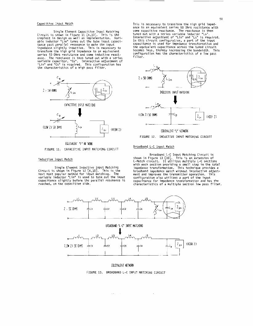
This i s necessary t o t r a n s f o r m t h e h i g h g r i d imped- ance t o an e q u i v a l e n t s e r i e s 50 Ohms r e s i s t a n c e w i t h some c a p a c i t i v e reactance. The reactance i s then tuned o u t w i t h a s e r i e s v a r i a b l e i n d u c t o r "Ls" . I n t e r a c t i v e adjustment o f " L i n " and "Ls" i s requ i red . I n t h i s c i r c u i t c o n f i g u r a t i o n , a p a r t o f t h e i n p u t capaci tance i s used f o r impedance t r a n s f o r m a t i o n and t h e e q u i v a l e n t capaci tance across t h e tuned c i r c u i t becomes l e s s , t he reby i n c r e a s i n g t h e bandwidth. c o n f i g u r a t i o n has t h e c h a r a c t e r i s t i c s o f a low pass f i 1 t e r .
T h i s
Z = 50 OHMS
C a p a c i t i v e I n p u t Match
7YC1 ZYC2 7 x 3 7< c4
S i n g l e Element C a p a c i t i v e I n p u t Match ing Th is i s t h e C i r c u i t i s shown i n F i g u r e 11 [6,10].
s i m p l e s t i n des ign as w e l l as implementat ion. V a r i - a b l e i n d u c t o r " L i n " tunes o u t t h e tube i n p u t capac i - tance p a s t p a r a l l e l resonance t o make t h e i n p u t impedance s l i g h t l y i n d u c t i v e . Th is i s necessary t o t r a n s f o r m t h e h i g h g r i d impedance t o an e q u i v a l e n t s e r i e s 50 Ohms r e s i s t a n c e and some i n d u c t i v e r e a c t - ance. The reactance i s t hen tuned o u t w i t h a s e r i e s v a r i a b l e c a p a c i t o r , 'ICs". I n t e r a c t i v e adjustment o f " L i n " and "Cs" i s r e q u i r e d . T h i s c o n f i g u r a t i o n has t h e c h a r a c t e r i s t i c s o f a h i g h pass f i l t e r .
,
C,
(LOW Z 1 50 OHMS
3
7 x 1 >KC2 7Y c3 7 Y c 4
Z -
(LOW Z 1 50 OHMS
50 OHMS
i c i I C 2 I C 3 Lc4
INDUCTIVE INPUT MATCHING
CAPACITIVE INPUT MATCHING
j L p (LOW Z 1 50 OHMS
(HIGH Z 1
(LOW Z 1 50 OHMS ;f;cP
EQUIVALENT 'L' NETWORK FIGURE 12. INDUCTIVE INPUT MATCHING C I R C U I T
Broadband L-C I n p u t Match EQUIVALENT 'L' NETWORK
FIGURE 11. CAPACITIVE INPUT MATCHING CIRCUIT
Broadband L-C I n p u t Match ing C i r c u i t i s Th is i s an e x t e n s i o n o f shown i n F i g u r e 13 [lo].
L-Match c i r c u i t . w i t h each s e c t i o n p r o v i d i n g a smal l s t e p i n t h e t o t a l impedance t r a n s f o r m a t i o n . broadband impedance match w i t h o u t i n t e r a c t i v e a d j u s t -
c o n f i g u r a t i o n a l s o u t i l i z e s a p a r t of t h e i n p u t capac i tance f o r impedance t r a n s f o r m a t i o n and has t h e c h a r a c t e r i s t i c s o f a m u l t i p l e s e c t i o n low pass f i l t e r .
I t u t i l i z e s m u l t i p l e L-C s e c t i o n s I n d u c t i v e I n p u t Match
S i n g l e Element I n d u c t i v e I n p u t Match ing Th is technique p rov ides a C i r c u i t i s shown i n F i g u r e 12 [6,10]. n e x t most popu la r method f o r i n p u t match ing. The ment and improves t h e t r a n s m i t t e r o p e r a t i o n . Th is v a r i a b l e i n d u c t o r " L i n " i s used t o tune o u t t h e i n p u t capaci tance s l i g h t l y before t h e P a r a l l e l resonance i s reached, on t h e c a p a c i t i v e s i d e .
Th is i s t h e
BROADBAND 'L-C' INPUT MATCHING
(HIGH Z 1
EQUIVALENT NETYORK
FIGURE 13. BROADBAND L-C INPUT MATCHING CIRCUIT
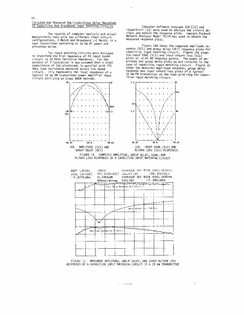
52 Computed And Measured Amplitude,’Group Delay Responses O f C a p a c i t i v e And Broadband I n p u t Match ing C i r c u i t s Computer so f tware programs ECA [ll] and
=Superstar= [12] were used t o analyze t h e c i r c u i t de- s igns and o b t a i n t h e response p l o t s . Hew le t t Packard Network Analyzer Model 3577A was used t o o b t a i n t h e measured response p lo t s *
F i g u r e 14A shows t h e computed amp l i t ude r e - sponse (S21) and group de lay (DLY) response p l o t s f o r c a p a c i t i v e i n p u t match ing c i r c u i t . F i g u r e 148 shows the i n p u t VSWR (V11) and i n p u t r e t u r n l o s s (S11) p l o t s a t -0.05 dB response p o i n t s . The peaks o f am- p l i t u d e and group de lay p l o t s do n o t c o i n c i d e i n t h e case o f c a p a c i t i v e i n p u t match ing c i r c u i t . F i g u r e 15 shows t h e measured amp l i t ude response, group de lay response and i n p u t r e t u r n l o s s p l o t s o f a t y p i c a l 20 kW FM t r a n s m i t t e r a t t h e tube g r i d r i n g f o r capac- i t i v e i n p u t match ing c i r c u i t .
The r e s u l t s o f computer a n a l y s i s and a c t u a l measurements made w i t h two d i f f e r e n t i n p u t c i r c u i t c o n f i g u r a t i o n s , C-Match and Broadband L-C Match, i n a r e a l t r a n s m i t t e r o p e r a t i n g a t 20 kW RF power a r e presented below.
Two i n p u t match ing c i r c u i t s were des igned t o t r a n s f o r m t h e h i g h impedance o f PA i n p u t tuned c i r c u i t t o 50 Ohms r e s i s t i v e impedance. purpose of i l l u s t r a t i o n i t was assumed t h a t a t o t a l capac i tance o f 165 p i c o f a r a d s i n p a r a l l e l w i t h 375 Ohms l o a d r e s i s t a n c e appeared across t h e tuned c i r c u i t . Th i s rep resen ts t h e i n p u t impedance o f a t y p i c a l 20 kW FM t r a n s m i t t e r power a m p l i f i e r i n p u t c i r c u i t u t i l i z i n g an Eimac 8989 t e t r o d e .
-30 1.2 : : : : : : : : : 20
For t h e
.. t t t t t t t t t ’ ’
s11
t t t t t t t
1.1 ..
t t t t t t t t t t t
t t t t t t t t t
t t t t t t t t t
i t t t t t t t t
95.37 95.5 95.63 95.37 95.5 95.63
14A. AMPLITUDE (91) AND 14B. INPUT VSWR (V11) AND GROUP DELAY (DLY)
FIGURE 14. COMPUTED AMPLITUDE, GROUP DELAY, VSWR, AND RETURN LOSS RESPONSES OF A C A P A C I T I V E INPUT MATCHING CIRCUIT
RETURN LOSS (S11) RESPONSES
R E F L E V E L / D I V M A R K E R 95 509 0 O O . O O O H z 202. 50nSEC 50. O O O n S E C D E L A Y (9) -7. 275dBm 0. 050dB MARKER 95 509 000. OOOHz
199. 95nSEC
-7. 28 1 dBm SPAN = 3 0 0 ~ H z MAG <E>
FIGUKt 15. MEASURED AMPLITUDE, GROUP DELAY, AND INPUT RETURN LOSS RESPONSES OF A CAPACITIVE INPUT MATCHING CIRCUIT I N A 20 kW TRANSMITTER
54
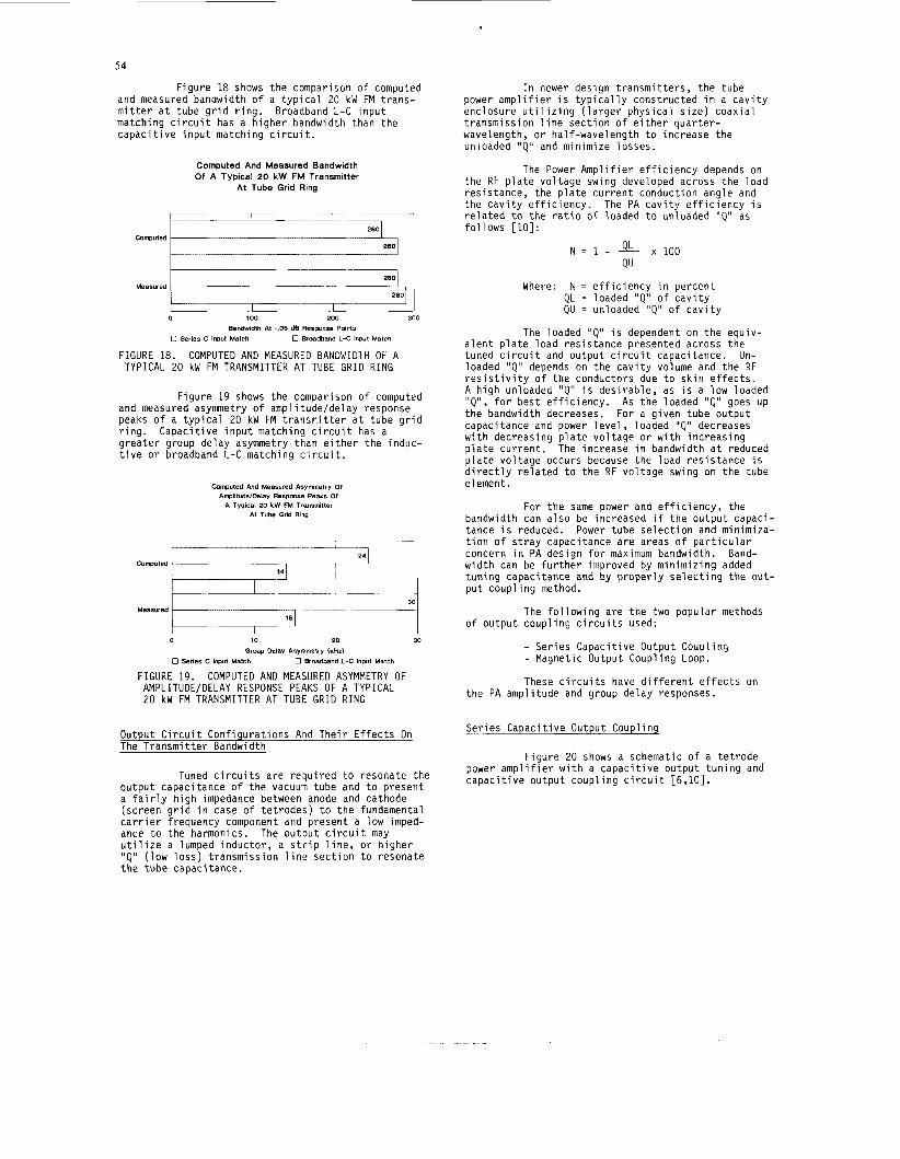
F i g u r e 18 shows t h e comparison o f computed and measured bandwidth o f a t y p i c a l 20 kW FM t r a n s - m i t t e r a t tube g r i d r i n g . Broadband L-C i n p u t match ing c i r c u i t has a h i g h e r bandwidth than t h e c a p a c i t i v e i n p u t match ing c i r c u i t .
Computed
Measured
Computed And Measured Bandwidth Of A Typical 20 kW FM Transmitter
At Tube Grid Ring
I ~- - - .--
-7
I
. 15
Measured
0 100 200 300
Bandwidth At -.OS dB Response Polnts
0 Series C Input Match 0 Broadband L-C Input Match
FIGURE 18. COMPUTED AND MEASURED BANDWIDlH OF A TYPICAL 20 kW FM TRANSMITTER A T TUBE G R I D R I N G
F i g u r e 19 shows t h e comparison o f computed and measured asymmetry o f a m p l i t u d e l d e l a y response peaks o f a t y p i c a l 20 kW FM t r a n s m i t t e r a t t ube g r i d r i n g . C a p a c i t i v e i n p u t match ing c i r c u i t has a g r e a t e r group de lay asymmetry than e i t h e r t h e induc- t i v e o r broadband L-C matching ( c i r c u i t .
Computed And Measured Asymmetry 01 ArnplitudelDehy Resprnsa Peaks of
A Typical 20 kW FM Transmitter At Tube Grid Ring
FIGURE 19. COMPUTED AND MEASURED ASYMMETRY OF AMPLITUDE/DELAY RESPONSE PEAKS OF A TYPICAL 20 kW FM TRANSMITTER AT TUBE G R I D R I N G
Output C i r c u i t C o n f i g u r a t i o n s And T h e i r E f f e c t s On The T r a n s m i t t e r Bandwidth
Tuned c i r c u i t s a r e r e q u i r e d t o resona te t h e o u t p u t capac i tance o f t h e vacuum tube and t o p resen t a f a i r l y h i g h impedance between anode and cathode (sc reen g r i d i n case o f t e t r o d e s ) t o t h e fundamental c a r r i e r f requency component and p resen t a low imped- ance t o t h e harmonics. u t i l i z e a lumped i n d u c t o r , a s t r i p l i n e , o r h i g h e r " Q " ( l o w l o s s ) t ransmiss ion l i n e s e c t i o n t o resonate t h e tube capaci tance.
The o u t p u t c i r c u i t may
I n newer des ign t r a n s m i t t e r s , t h e tube power a m p l i f i e r i s t y p i c a l l y cons t ruc ted i n a c a v i t y enc losu re u t i l i z i n g ( l a r g e r p h y s i c a l s i z e ) c o a x i a l t ransmiss ion l i n e s e c t i o n o f e i t h e r q u a r t e r - wavelength, o r ha l f -wave leng th t o i nc rease t h e unloaded 'IQ" and m in im ize l osses .
The Power A m p l i f i e r e f f i c i e n c y depends on t h e RF p l a t e v o l t a g e swing developed ac ross t h e l o a d r e s i s t a n c e , t h e p l a t e c u r r e n t conduc t ion ang le and t h e c a v i t y e f f i c i e n c y . The PA c a v i t y e f f i c i e n c y i s r e l a t e d t o t h e r a t i o o f loaded t o un loaded " Q " as f o l l o w s [ lo] :
N = 1 - & x 1 0 0 QU
Where: N = e f f i c i e n c y i n p e r c e n t QL = loaded " Q " o f c a v i t y QU = unloaded 'IQ" o f c a v i t y
The loaded 'IQ" i s dependent on t h e equ iv - a l e n t p l a t e l o a d r e s i s t a n c e presented ac ross t h e tuned c i r c u i t and o u t p u t c i r c u i t capaci tance. Un- loaded " Q " depends on t h e c a v i t y volume and t h e RF r e s i s t i v i t y o f t h e conductors due t o s k i n e f f e c t s . A h i g h unloaded " Q " i s d e s i r a b l e , as i s a l ow loaded " Q " , f o r b e s t e f f i c i e n c y . As t h e loaded "Q" goes up t h e bandwidth decreases. For a g i v e n tube o u t p u t capac i tance and power l e v e l , 1 oaded " Q " decreases w i t h decreas ing p l a t e v o l t a g e o r w i t h i n c r e a s i n g p l a t e c u r r e n t . The inc rease i n bandwidth a t reduced p l a t e v o l t a g e occurs because t h e l o a d r e s i s t a n c e i s d i r e c t l y r e l a t e d t o t h e RF v o l t a g e swing on t h e tube e l ement .
For t h e same power and e f f i c i e n c y , t h e bandwidth can a l s o be i nc reased i f t h e o u t p u t capac i - tance i s reduced. Power tube s e l e c t i o n and min imiza- t i o n o f s t r a y capac i tance a r e areas o f p a r t i c u l a r concern i n PA des ign f o r maximum bandwidth. w i d t h can be f u r t h e r improved by m i n i m i z i n g added t u n i n g capac i tance and by p r o p e r l y s e l e c t i n g t h e o u t - p u t c o u p l i n g method.
o f o u t p u t c o u p l i n g c i r c u i t s used:
Band-
The f o l l o w i n g a re t h e two popu la r methods
- Ser ies C a p a c i t i v e Output Coup l i ng - Magnet ic Output Coupl ing Loop.
These c i r c u i t s have d i f f e r e n t e f f e c t s on t h e PA amp l i t ude and group de lay responses.
Se r ies C a p a c i t i v e Output Coup l i ng
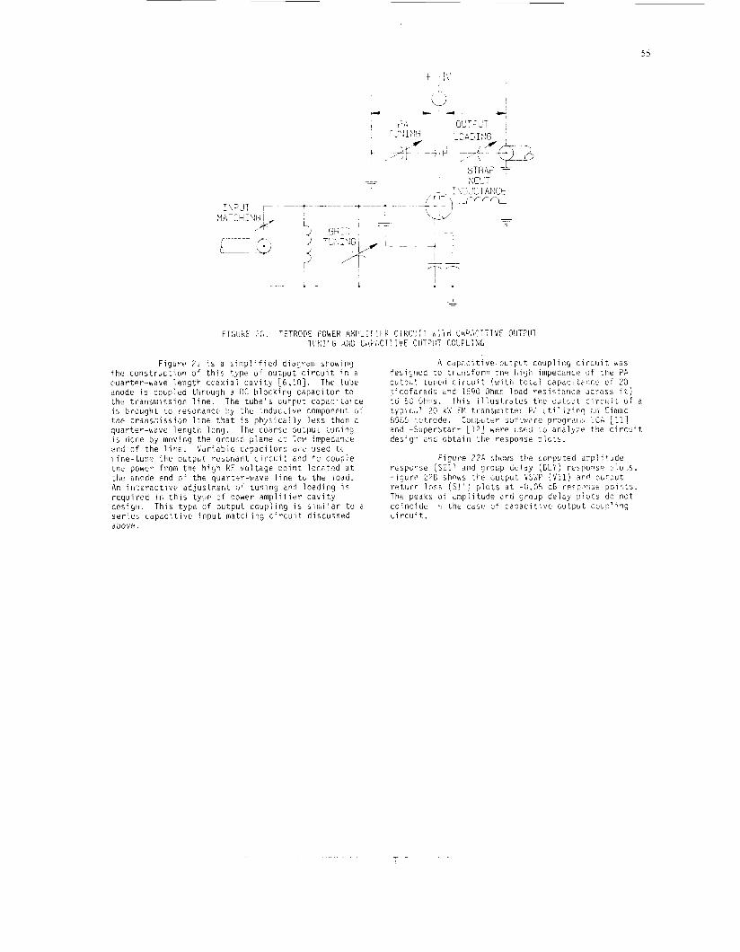
F i g u r e 20 shows a schematic o f a t e t r o d e power a m p l i f i e r w i t h a c a p a c i t i v e o u t p u t t u n i n g and c a p a c i t i v e o u t p u t c o u p l i n g c i r c u i t [6,10].
5 5
t "b'
I i ~~ c
F i g u r e 2: i s a s i m p l i f i e d diacjraii showins ttx c o n s t r u c t i o n o f t h i s t y p e o f o u r p u t c i r c u i t i r : a cuar ter -wave l e n g t h c c a x i a l c3Vit.y [6,1O]. The tube cnode i s , c c b p i e a tl-LrcJuSh 6 DC h l o c k i r g c a p a c i t o r t o the transr,i:csion l i n e . The t u b e ' s c i i t p t i t capa i s S r o u g h i LO resonant? hy t h e induc-Live comporetil. cif t h e t r a n s r i s s i o n l i n t t h a t i s p h 2 s i c a l l y l ess t h a n a q u a r t e r - w v e l e n g t h l o n g . The coarse outpL;t t u n i n g i s i c n e by rnuving t h e Groui-i?, p l a n e d i ',mi iwpedanie e t i d of t h e l i w . V a r i a b i i capac i to r : ti1.e used tc. .I ine- tu r ie t h e o u t p u t rescr,anl; c i r c [ ! i t and t o coirple t h e power f r o m t h e h i g h KF v o l t a g e p o i n t l o c a t x l a t t h e iir;ode end o f t h e quar ter -wave l i n e t c t h e j o d d . An i n t e r a c t i v e ad jus tmer l t C J ~ run ing and l o a d i n g i s r e q u i r e d i n t h i s t y p e o f power a m p l i f i e r c a v i t y des;yti. T h i s t y p e o f o u t p u t c o u p l i n g i s s i m i l a r t o a s e r i c 3 c a p a c i i i v e i n p u t rnatct,it:g c i r c u i t d iscussed above.
A c i i ~ ; i i t i v e . o c ? p l ; t coupl i t :9 c i r c u i t SS d e s i y i i e d t o t r c r l s f o r m til? h i 2 l i iiripebanct: o f t h e ?A o u t p u t tuned c i r c u i t ( w i t h t o t o i capac i t t i i cc . c f 23 ;3 ico far?ds ur?d 15510 Ohn.2 l o a d r e s i s t t r i c e dcros:, i t ) t o 5C Ohms. l h i s i l l u s t . r a t e s t h e ouj.bCt c i r c u i t of 2 t y p . l ~ < ~ ! 20 kW FY t r a i i s i : : i t t e r P;, i i t i l i z i r - 9 ; i t i Einiac b%'1 ye t rode. h i p u t e r softv.i.re prograi:.ii; Lei; 2 n d =SuperStar- 1121 were i : s t d t o s n a l y y e t h e c i r c L i t des ig i i o b t a i n i i i f response p l c t s .
Fi9ut-e 7 2 1 strows t h e c w p o t t d amp1 i tude rc.spc;ril;e ( 5 2 1 ) and group d e l a y (C1.Y: respons? p1oi.s. Figurt: :?E shpws ?he :;utput \:WP ( V l l ) arr! o u t p u t r e t u r r l o s s ( S l l ) p l o t s a t -('i.Ob dB resp,'li:t i j o i r , t s . The peaks o f u r i p l i t u d e and group delGy p l o t s do n o t c o i n c i d e ~ I I t h e cast) U: c z p a c i t i v e w t p b t c o u p l i n g c i r c u i t.
56
EXHAUST A I R 4 tHV A
SHORTING GROUND PLANE COARSE/FINE TUNING
P t I F C
4
F t
SHORTING GROUND PLANE COARSE/FINE TUNING
H I G H RF P O T E N T I A L
RF OUTPUT m jONATING' I I E L E C T R I C
OUTPUT COUPLING (LOADING)
DLY
t + + t + + + + +
t t t t t i i t t
t t t t t t , + t
t + t t + + + + ,
95.33 95.5 95.67
1 . 2
95.33 95.5 95.67
Magnetic Output Coupl ing Loop
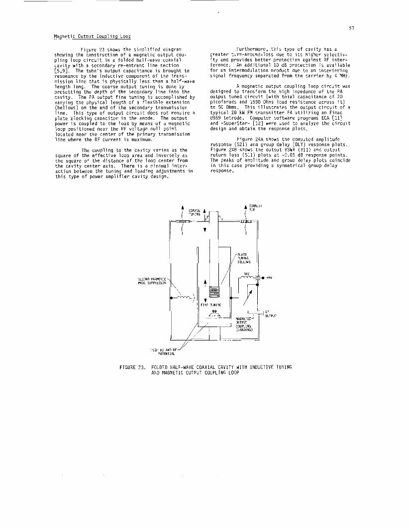
F igu re 23 shows t h e s i m p l i f i e d diagram showing the c o n s t r u c t i o n o f a magnet ic o u t p u t cou- p l i n g l o o p c i r c u i t i n a f o l d e d hal f -wave c o a x i a l c a v i t y w i t h a secondary r e - e n t r a n t l i n e s e c t i o n [5,9]. The t u b e ’ s o u t p u t capac i tance i s b rough t t o resonance by t h e i n d u c t i v e component o f t h e t r a n s - m iss ion l i n e t h a t i s p h y s i c a l l y l e s s than a hal f -wave l e n g t h long. The coarse o u t p u t t u n i n g i s done by p r e s e t t i n g t h e depth o f t h e secondary l i n e i n t o t h e c a v i t y . The PA o u t p u t f i n e t u n i n g i s accomplished by v a r y i n g t h e p h y s i c a l l e n g t h o f a f l e x i b l e ex tens ion ( b e l l o w s ) on t h e end o f t h e secondary t ransmiss ion l i n e . Th is t ype o f o u t p u t c i r c u i t does n o t r e q u i r e a p l a t e b l o c k i n g c a p a c i t o r i n t h e anode. The o u t p u t power i s coupled t o t h e l o a d by means o f a magnetic l oop p o s i t i o n e d near the RF v o l t a g e n u l l p o i n t l o c a t e d near t h e c e n t e r o f t h e p r imary t ransmiss ion l i n e where t h e RF c u r r e n t i s maximum.
The c o u p l i n g t o t h e c a v i t y v a r i e s as t h e square o f t h e e f f e c t i v e l o o p area and i n v e r s e l y as t h e square o f t h e d i s t a n c e o f t h e l o o p c e n t e r f rom t h e c a v i t y c e n t e r a x i s . There i s a min imal i n t e r - a c t i o n between t h e t u n i n g and l o a d i n g adjustments i n t h i s t y p e o f power a m p l i f i e r c a v i t y design.
Furthermore, t h i s t y p e o f c a v i t y has a g r e a t e r turn-around- loss due t o i t s h i g h e r s e l e c t i v - i t y and p rov ides b e t t e r p r o t e c t i o n a g a i n s t RF i n t e r - ference. An a d d i t i o n a l 10 dB p r o t e c t i o n i s a v a i l a b l e f o r an i n t e r m o d u l a t i o n p roduc t due t o an i n t e r f e r i n g s i g n a l f requency separated f rom t h e c a r r i e r by 4 MHz.
A magnet ic o u t p u t c o u p l i n g l oop c i r c u i t was designed t o t r a n s f o r m t h e h i g h impedance o f t he PA o u t p u t tuned c i r c u i t ( w i t h t o t a l capaci tance o f 20 p i c o f a r a d s and 1590 Ohms l o a d r e s i s t a n c e across i t ) t o 50 Ohms. Th is i l l u s t r a t e s t h e o u t p u t c i r c u i t o f a t y p i c a l 20 kW FM t r a n s m i t t e r PA u t i l i z i n g an Eimac 8989 t e t r o d e . Computer so f tware programs ECA [ll] and =Superstar= [ 1 2 ] were used t o analyze t h e c i r c u i t des ign and o b t a i n t h e response p l o t s .
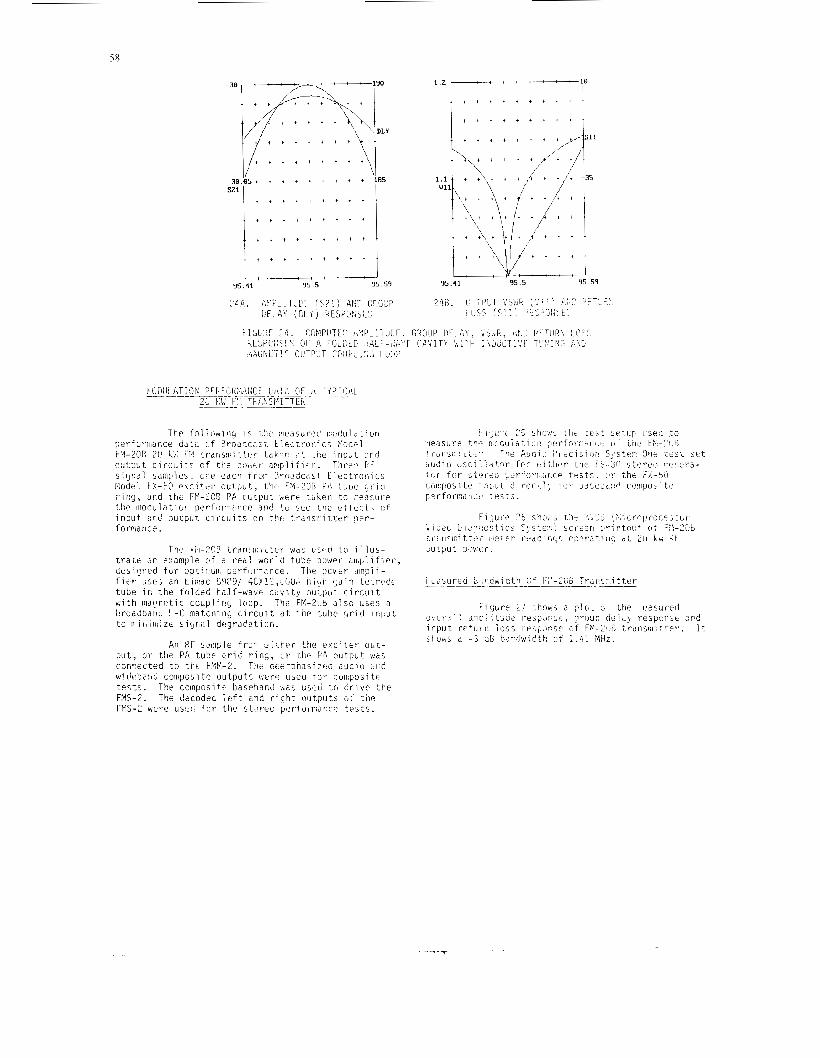
F igu re 24A shows t h e computed amp l i t ude response (S21) and group de lay (DLY) response p l o t s . F igu re 248 shows t h e o u t p u t VSWR (V11) and o u t p u t r e t u r n l o s s (S11) p l o t s a t -0.05 dB response p o i n t s . The peaks o f amp l i t ude and group de lay p l o t s c o i n c i d e i n t h i s case p r o v i d i n g a symmetr ica l group de lay response.
COARSE TUNING
SECOND HARMONIC MODE SUPPRESSOR
~I /
II : ]NE TUNING
A
’rr
I I
rn +Hv +HV
RF
WTPUT COUPLING (LOADING)
RF
WTPUT COUPLING (LOADING)
I // I I IJ
HIGH DC AND RF POTENTIAL
FIGURE 23. FOLDED HALF-WAVE COAXIAL CAVITY WITH I N D U C T I V E TUNING AND MAGNETIC OUTPUT COUPLING LOOP
58
-30
+ + + + +
t t t t i t t
sz1 I , t + + + t + i t ''
.. + + t + + t t i +
.. t + t + + t t t t
.. + + + + + + + t t ''
l , t * + + t + i t l
.. + + t + + t t i +
.. t + t + + t t t t
.. + + + + + + + t t ''
9 5 . 4 1 95.5
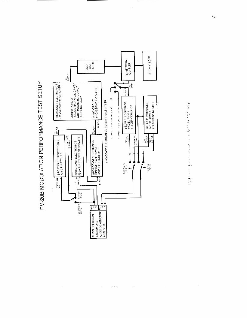
The i h - ? C B t ranr i1 , i i ter wai; uced t n i l l u s - t r a c e i r Pxmplp r l f a redl wor-d t u b e power ; : l ,b l i f ie i . , desigced f o r o p t i r t u i p e r f u i m n c e . The i )wtr dinpi i- f i e r 1 : w 5 an Ein!ac &W3/ 4cXI?,-(J(jA high r,ain t e t r c d t tube ir: t h e tuldecl half-wave ct :vi ty outpiit c i r c u i t with inapnctic coliplir!c, l c rop. -:hi. FY-?(;Lj a l s o uses a Lircddbdili I.-C rnatchiiig c i r c u i t d t t h p t u b e g r i d i n p u t t o p-itliiliizf sicJrial df?grac'atioii.
An RF s w p l e froni c.i:,Per t he exciter o u t - p u t , o r the PA tube c r i d r i n g , cir .cl:? P.4 oiit.put was conr.ected t o t k t F l W 2 . The c wideba:ld composite o u t p u t s \';er+ useo itii- :oinposi t F t e s t i . l h e coinposite baseband 'ha: used t c J < r i v e the FMS-2. The i!?codec - , e f t and r-lcht output5 G : tile FP5-2 were u s e d f r r the s t ' r e o per fomsr , ce t e s t s .
a. 3 t- W cn t- cn W t- W 0 Z 3 [I: 0 LL [I: LLI a, Z 0 i= 4 3 n 0 2 a v 2
a
0
LL
I
&$I-
a W
E I 0 L U a t rn 0 N
._
L
- c
. .. , i.
60
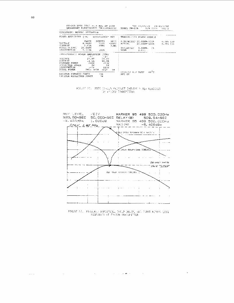
VOLTAGE CURRENT POWER O U T P U T D I S S I P A T I O N
P L A T E S C R E E N G R I D 1 A U T H O R I Z E D 2 0 . 0 0 K W = 1 0 0 $ 0.OKW E R P 8 . 9 4 K V 7 1 0 V - 2 9 8 V 1 A C T U A L 2 0 . O O K W = l O O % O.0KW E R P
2 . 8 1 A 1 4 9 M A 3 1 M A 2 0 . 0 0 K W R E F L E C T E D O.OOKW= 0 %
I N T E R M E D I A T E POWER A M P L I F I E R ( I P A ) -1- - 2 -
VOLTAGE 2 7 . 9 V 2 8 . 0 V CURRENT 1 1 . 4 a 11.3A i FORWARD POWER 2 0 4 W 2 0 3 W I R E F L E C T E D POWER 2W 1 w D I S S I P A T I O N 1 1 4 W 1 1 3 W ~
T O T A L POWER FWD= 3 6 7 W R F L = I W
E X C I T E R FORWARD POWER 3 6 W E X C I T E R R E F L E T E D POWER 1 W I
EXHAUST A I R T E M P = 4 6 . C _---____---________-____________________ 1 A P C ON
R E F LEVEL /D:V M A R K E R 95 499 5 0 0 . O O O H z 520. O O r i S E C 50. O O O n S E C D E L A Y <B> 509. 5 4 n S E C -5. 4 n n d ~ m 1. ocndB MARKER 95 499 5 0 0 . 0 O O H z
M A G < B > -5. 406dBm T - - - --- - - - - r--
D B INPVPU 7 M a i q
XMrR O U T P Y T --- ___-_._
-
61
028 002 r-- ,022
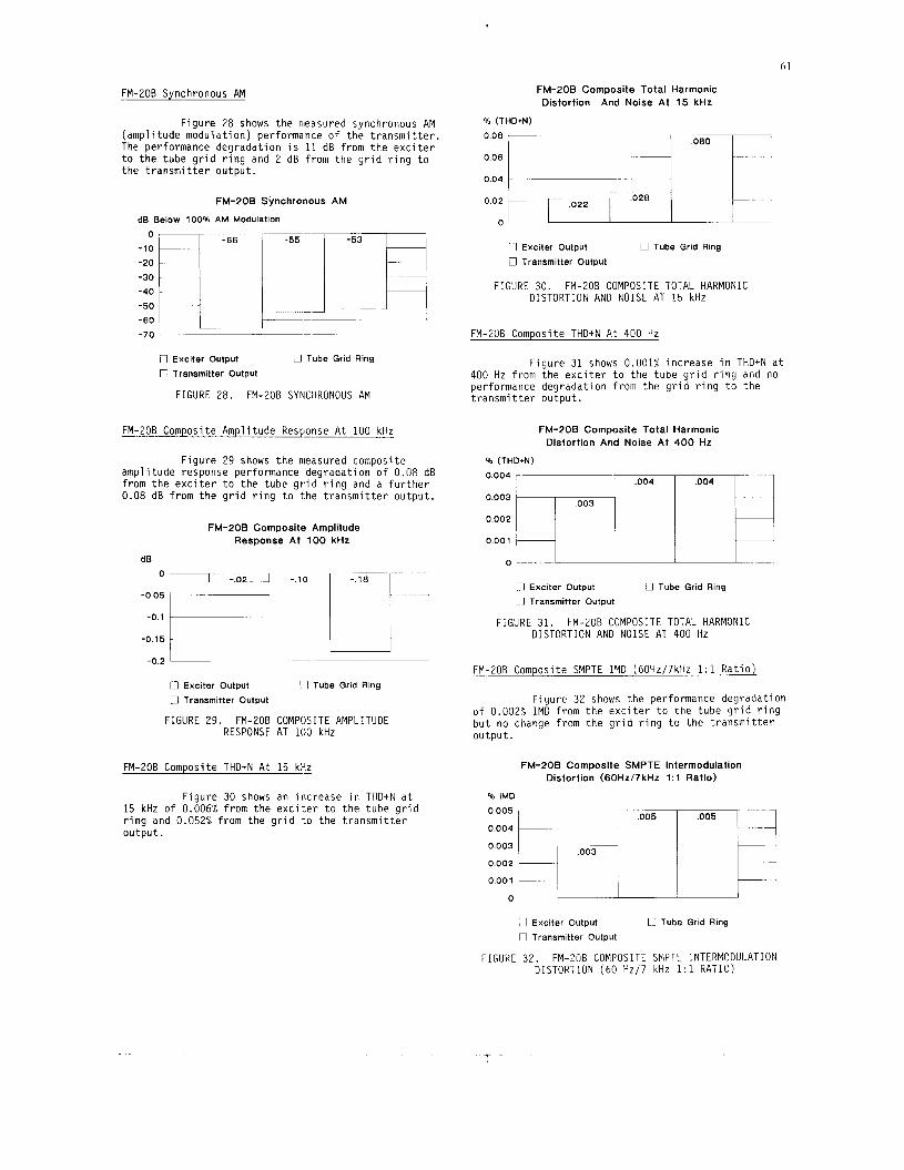
FM-20B Synchronous AM
~
F i gu re 28 shows t h e measured synchronous AM (amp1 i tude modu la t i on ) performance o f t h e t r a n s m i t t e r . The performance degrada t ion i s 11 dB f rom t h e e x c i t e r t o t h e tube g r i d r i n g and 2 dB f rom t h e g r i d r i n g t o t h e t r a n s m i t t e r o u t p u t .
FM-POB Synchronous AM
dB Below 100% AM Modulation
-,:r;..-ril ~~ -20
-30 -40 -50 ~
-60
-70
-,
~~~
I ~ ~ _ _ _ ~ ~
U Exciter Output
0 Transmitter Output
U Tube Grid Ring
FIGURE 28. FM-206 SYNCHRONOUS AM
FM-EOB Composite Ampl i tude Response A t 100 kHz
F i g u r e 29 shows t h e measured composite amp l i t ude response performance degrada t ion o f 0.08 dB f rom t h e e x c i t e r t o t h e tube g r i d r i n g and a f u r t h e r 0.08 dB f rom t h e g r i d r i n g t o t h e t r a n s m i t t e r ou tpu t .
FM-POB Composite Amplitude Response At 100 kHz
dB
-0.15
-0.2
U Exciter Output 0 Transmitter Output
FIGURE 29. FM-2OB RESPONSE
17 Tube Grid Ring
COMPOSITE AMPLITUDE AT 100 kHz
FM-20B Composite THD+N A t 15 kHz
F igu re 30 shows an inc rease i n T H D t N a t 15 kHz o f 0.006% f rom t h e e x c i t e r t o t h e tube g r i d r i n g and 0.052% f rom t h e g r i d t o t h e t r a n s m i t t e r o u t p u t .
FM-POB Composite Total Harmonic Distortion And Noise At 15 kHz
% (THD+N)
008- -
0 04
U Exciter Output
n Transmitter Output
0 Tube Grid Ring
FIGURE 30. FM-206 COMPOSITE TOTAL HARMONIC DISTORTION AND N O I S E AT 15 kHz
FM-20B Composite THDtN A t 400 Hz
F i g u r e 31 shows 0.001% inc rease i n THDtN a t 400 Hz f rom t h e e x c i t e r t o t h e tube g r i d r i n g and no performance degrada t ion f rom t h e g r i d r i n g t o t h e t r a n s m i t t e r ou tpu t .
FM-POB Composite Total Distortion And Noise At
% (THD+N)
0.003
0.002
0001 I
Harmonic 400 Hz
I E rl Exciter Output n Transmitter Output
U Tube Grid Ring
FIGURE 31. FM-206 COMPOSITE TOTAL HARMONIC DISTORTION AND N O I S E AT 400 Hz
FM-206 Composite SMPTE I M D (60Hz/7kHz 1:l R a t i o )
F igu re 32 shows t h e performance degrada t ion o f 0.002% I M D f rom t h e e x c i t e r t o t h e tube g r i d r i n g b u t no change f rom t h e g r i d r i n g t o t h e t r a n s m i t t e r ou tpu t .
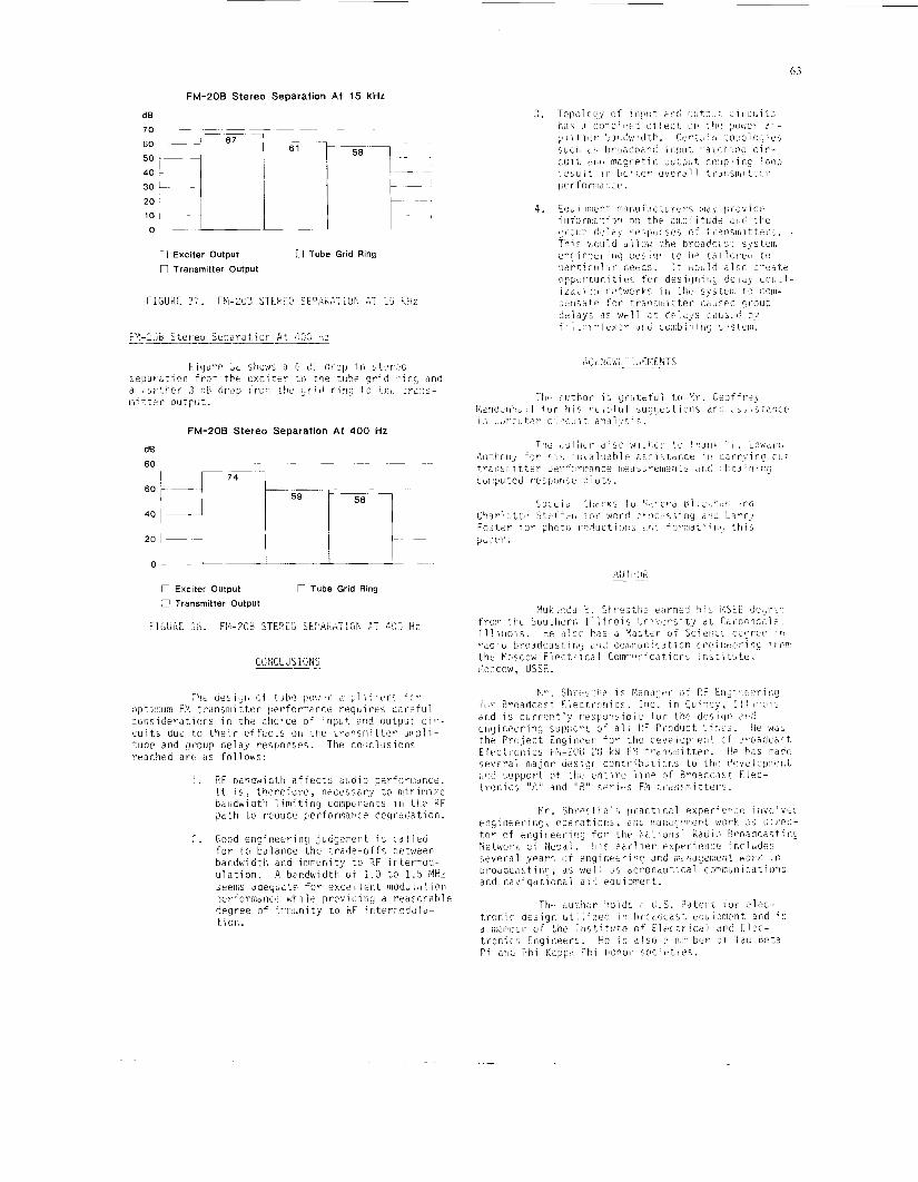
Figurr. L O shows ?I G cT- a rcp in st;>r?:c :epdi.ition f ro r , t b t c x c i t e r L O tbe +ubi. g r i d r inc; uno a t t i r t b e r 3 r!P rirop f r o m t h e g r i d r i n g t,o i k ~ t r a n s - 1-1; b t e r outFtit.
FM-PO0 Stereo Separation At 400 Hz
A ii l h LI k n Exciter Output U Transmitter Output
n Tube Grid Ring
FILbKC 3G. Fi"-?OB STEF.CG Sti'AKAT:TiF* F T 4!10 Hi!
C C N C L U S ION-!
The d e s i g r i Gf tuhe p o w r ;n .pl i f i t?rr f t r :)ptimum FP, t rdnsn i i t t c r p r f o r m r c e r e q u i re5 c s r e f u l cclnsiderat icns i n t h e clicice of i n p L t 3 r d ou tp i i : c i v - c u i t s dut t o t h e i r e f f e c t s on t h e Lrdnsmi t t e r jiiipli- tude and g r o u p delay respon:,es. The cociclusiiitls rrdclied a r c <is fo l lows :
1. P F bandwidtti a f t e c t ; a u d i o perfori.:ancti. I t i s , t h e r e f o r e , neces;ary t o iniririize bdrldwidttl l i m i t i n g coinpLnents i i i t k P F Gath t o reolice F1erforrn;ricr deg radd t ion .
2. Good engi i ieer ing judcjcvent i s c a l l e d f o r t.o tla:aiice t h e t r a d e - o f f s Lictwern bandkidtli and i r imni t y t o RF iriternod- u l a t i o n . A hzndwidth of 1 .0 t o 1 . 5 W z s e e i i , ~ aaequatc. f o r exc;.] lei:t inoduliition :)erformane€ w b i I s prcvidiny a r eascnab le degree o f ir;iiiun.ity t o hF intermoddlc- t i on.
64
REFERENCES
[l] Reference Data f o r Radio Ehgineers, Howard W. Sams & Co., Inc. , S i x t h E d i t i o n 1983.
[ Z ] F r e d e r i c k Terman, E l e c t r o n i c and Radio Engineer ing, McGraw-Hil l Book Company, 1955.
[3] Samuel Seely, E lect ron-Tuhe C i r c u i t s , McGraw-Hil l Book Company, 1950.
r 4 1 Herbe r t L. Krauss. Char les W . Bos t ian . and _ _ F r e d e r i c k H. Raab; S o l i d S t a t e Radio Engineer ing, John W v S o n s , 1980.
[5] K e i t h Henney ( E d i t o r i n C h i e f ) , Radio Eng ineer ing Handbook, McGraw-Hil l Book Company, 1950.
[6] E.B. C r u t c h f i e l d ( E d i t e d By) , NAB Eng ineer ing Handbook, N a t i o n a l A s s o c i a t i o n o f Broadcasters , Seventh E d i t i o n , 1985.
[ 7 ] Geo f f rey N. Mendenhall , "The Composite S igna l - Key t o Q u a l i t y Broadcast ing," Broadcast E l e c t r o n i c s , I nc . , 1981.
[8] Edward J . Anthony, "Optimum Bandwidth f o r FM Transmission," Broadcast E l e c t r o n i c s , Inc. , 1989.
Geof f rey N. Mendenhall , " A Study o f RF I n t e r m o d u l a t i o n Between FM Broadcast T r a n s m i t t e r s Shar ing F i l t e r p l e x e d o r CO-located Antenna Systems," Broadcast E l e c t r o n i c s , I nc .
i.T.M. L y l e s and Mukunda B. Shrestha, T r a n s m i t t e r Performance Requirements f o r
S u b c a r r i e r Operation," Broadcast E l e c t r o n i c s , I nc .
" E l e c t r o n i c C i r c u i t Ana lys i s 2.31 MS-DOS Version," Copy r igh t 1988 by Tatum Labs, I n c .
"=SuperStar= Vers ion 3.2," Copyr igh t 1988 by C i r c u i t Busters , I nc .