41
Design of Vacuum Chambers of SSRF Storage Ring Yonglin. Chen, Dikui. Jiang SSRF Vacuum Group Shanghai Institute of Applied Physics (SINAP) China Academy of Sciences
| Date post: | 13-Dec-2015 |
| Category: |
Documents |
| Upload: | berniece-small |
| View: | 223 times |
| Download: | 3 times |
Design of Vacuum Chambers of SSRF Storage Ring
Yonglin. Chen, Dikui. Jiang
SSRF Vacuum Group
Shanghai Institute of Applied Physics(SINAP)China Academy of Sciences
Key points of chamber design
1, The structure of chambers, material, strength, magnetic permeability
2, Mechanical stability, support, baking in-site
3, Thermal stability, thermal calculation, cooling
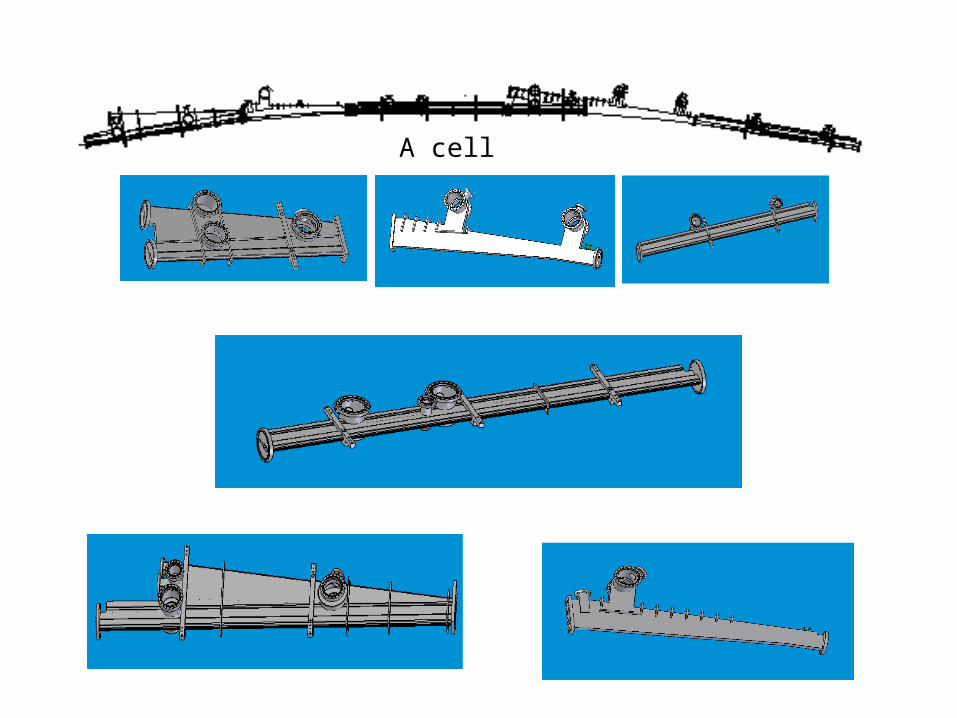
A cell
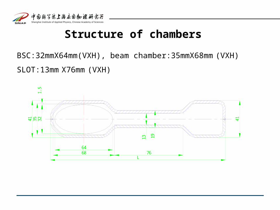
Structure of chambers
BSC:32mmX64mm(VXH), beam chamber:35mmX68mm (VXH)
SLOT:13mm X76mm (VXH)
3541
68 76L
13
41
19
321.
5
64
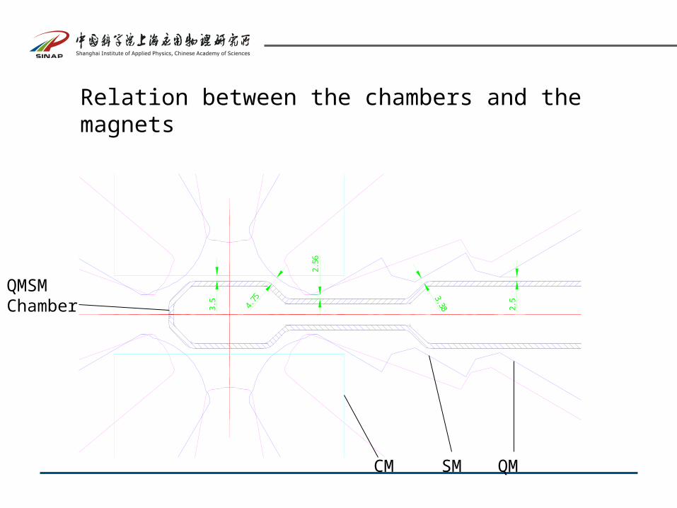
Relation between the chambers and the magnets
3.5
2.5
2.56
4.75
3. 38
QMSM Chamber
QMSMCM
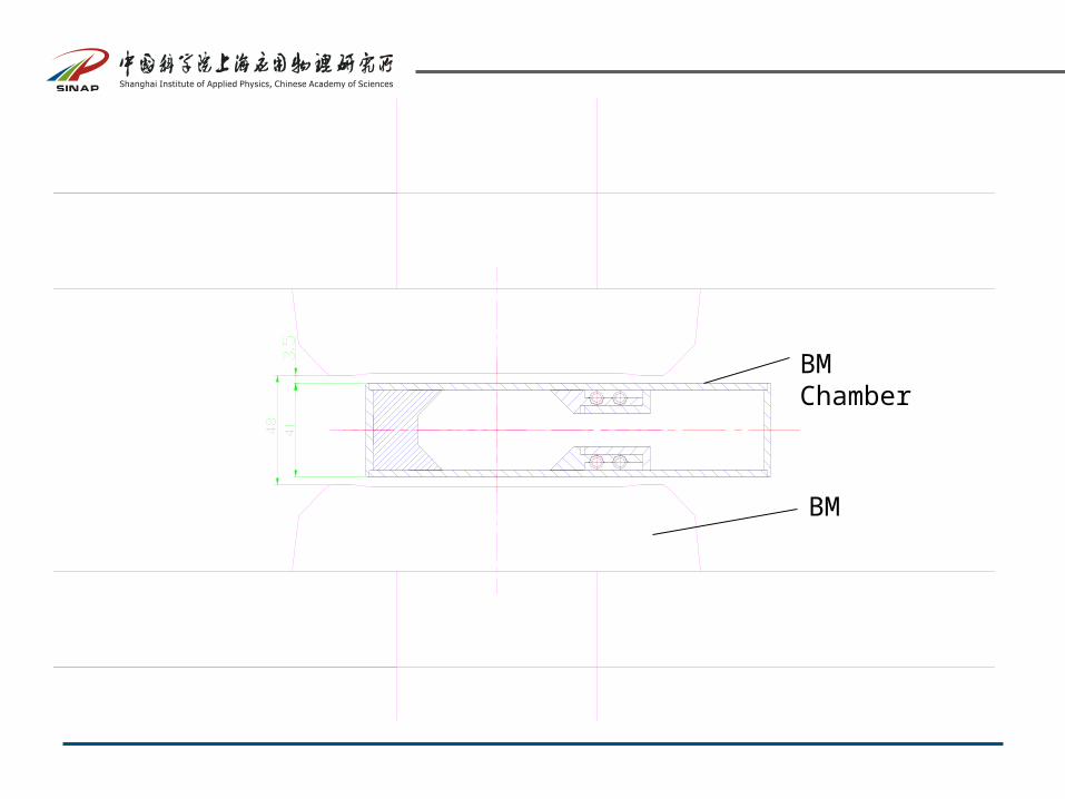
BM Chamber
BM
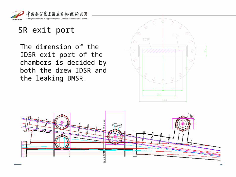
SR exit port
The dimension of the IDSR exit port of the chambers is decided by both the drew IDSR and the leaking BMSR.
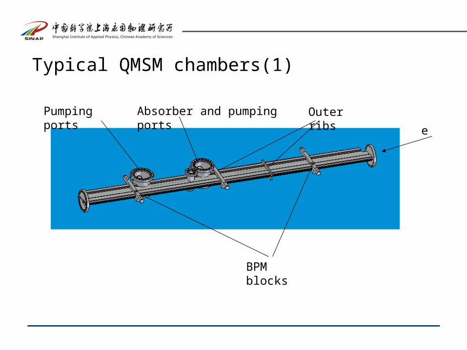
Typical QMSM chambers(1)
e
BPM blocks
Outer ribsAbsorber and pumping portsPumping ports
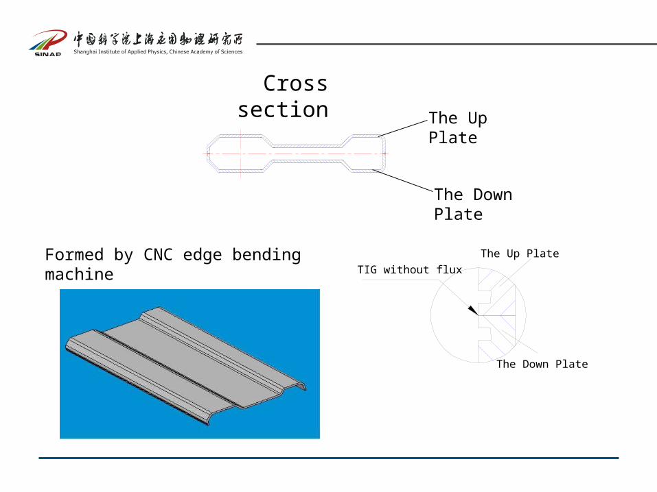
Cross section
The Up Plate
The Down Plate
TIG without flux
The Up Plate
The Down Plate
Formed by CNC edge bending machine
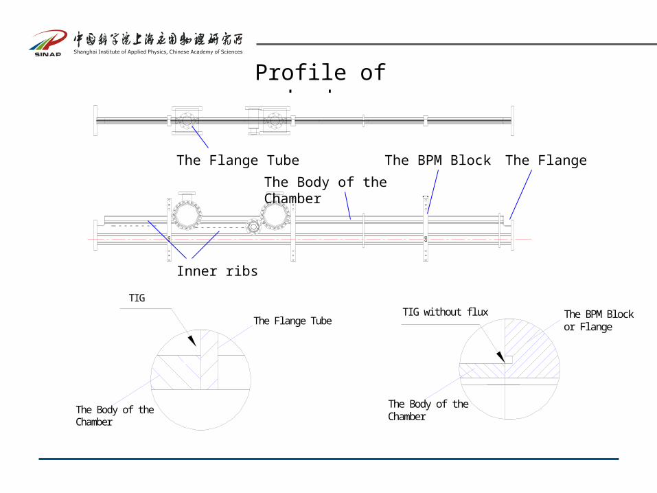
Profile of chamber
TI G wi thout fl ux The BPM Bl ock or Fl ange
The Body of the Chamber
TI G
The Body of the Chamber
The Fl ange Tube
The BPM Block The FlangeThe Flange Tube
The Body of the Chamber
Inner ribs
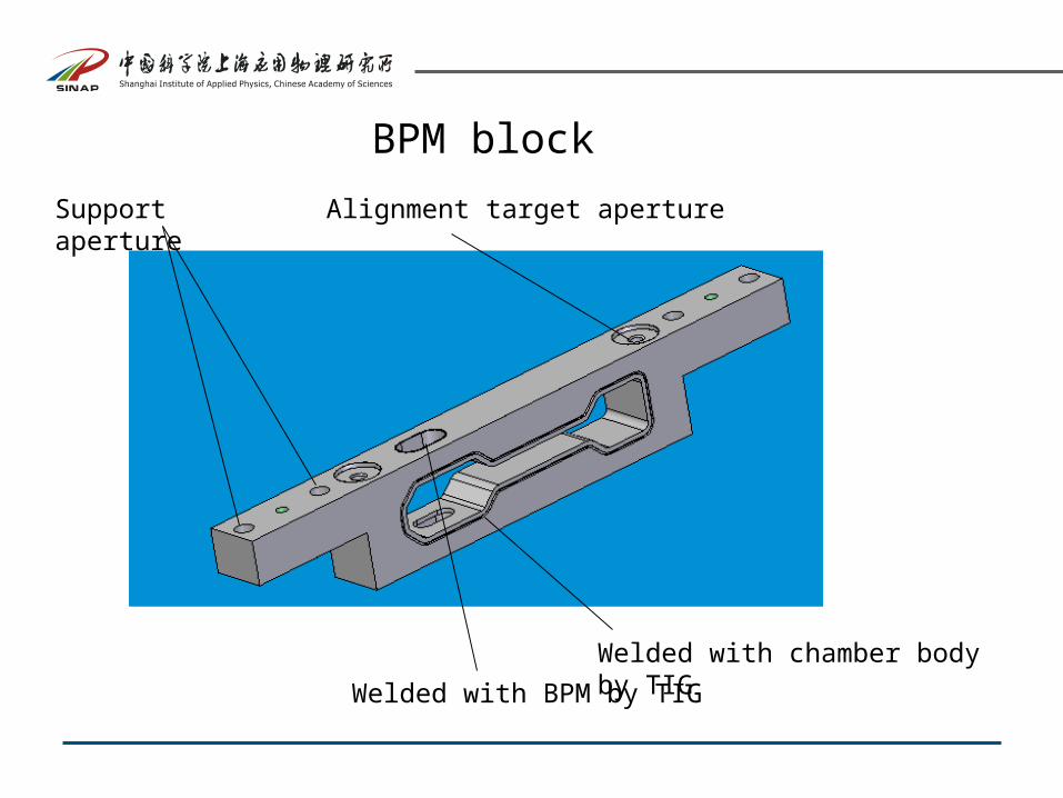
BPM block
Welded with chamber body by TIG
Welded with BPM by TIG
Alignment target apertureSupport aperture
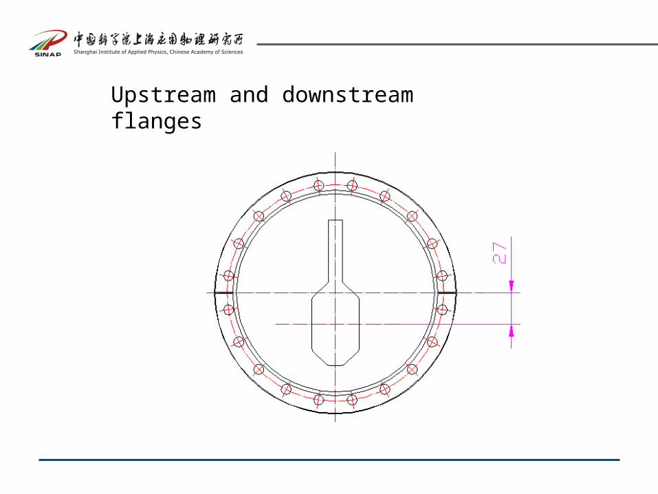
Upstream and downstream flanges
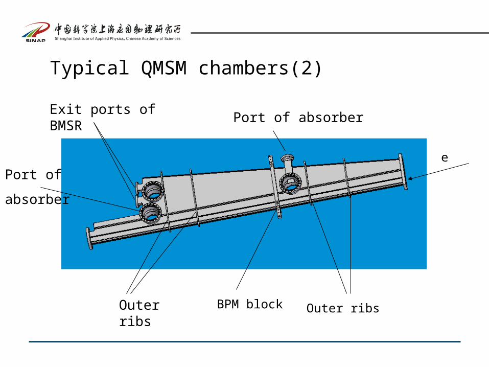
BPM blockOuter ribs Outer ribs
Exit ports of BMSRPort of absorber
Port of
absorber
e
Typical QMSM chambers(2)
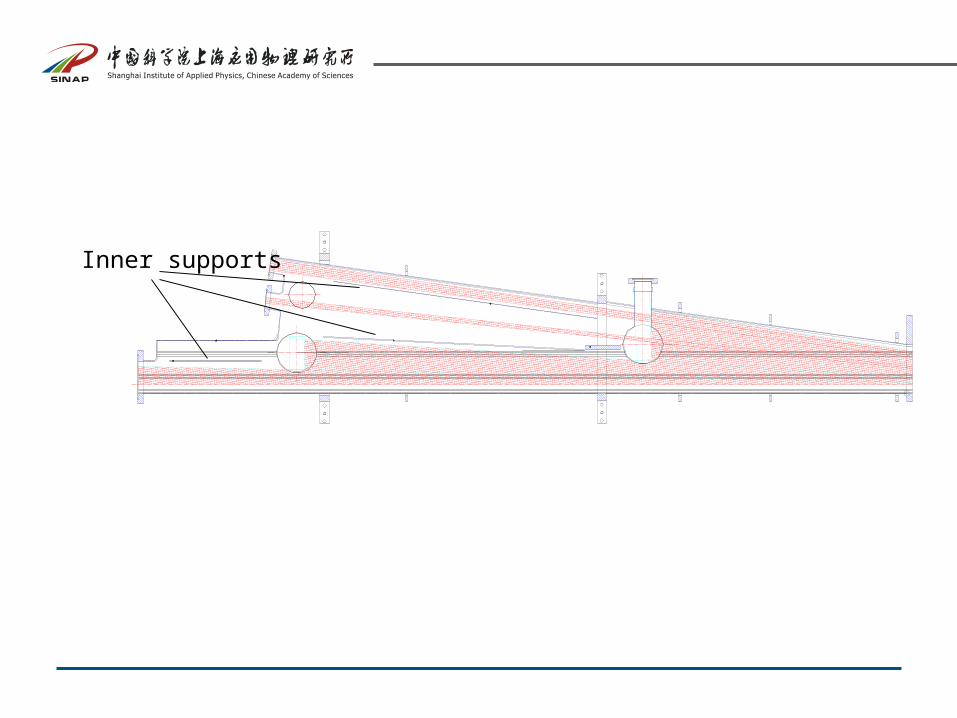
Inner supports
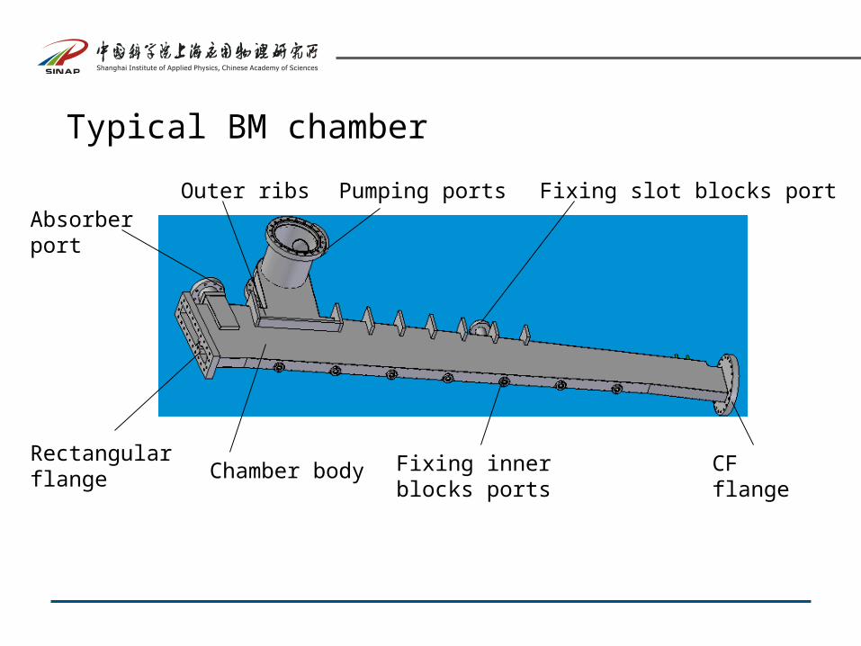
Typical BM chamber
Pumping portsOuter ribs
Chamber bodyRectangular flange
CF flange
Absorber port
Fixing slot blocks port
Fixing inner blocks ports
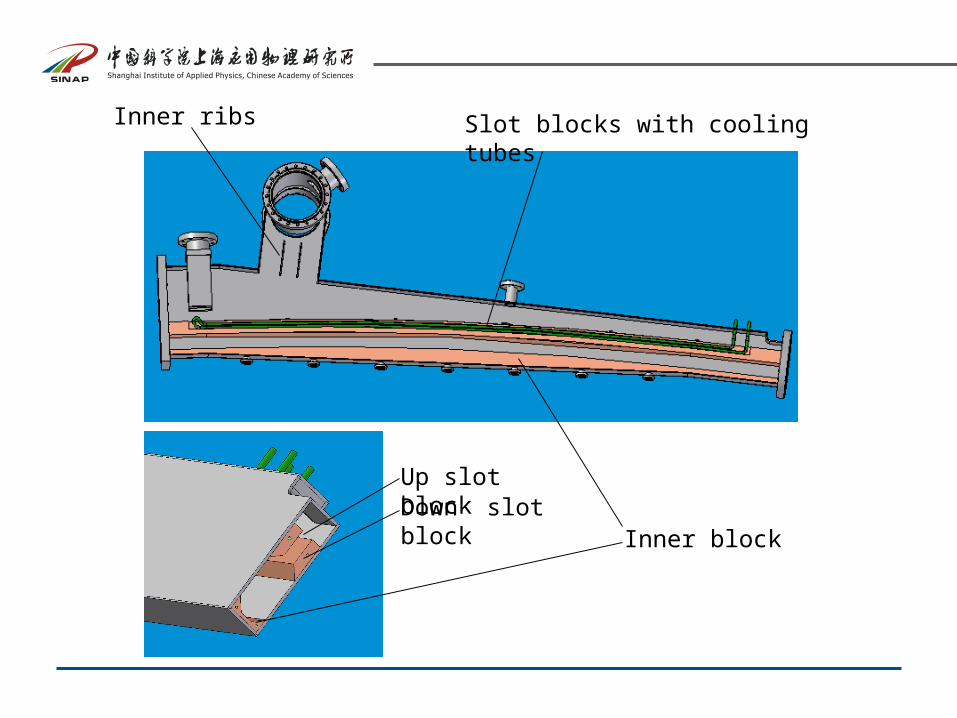
Inner ribs Slot blocks with cooling tubes
Inner block
Up slot blockDown slot block
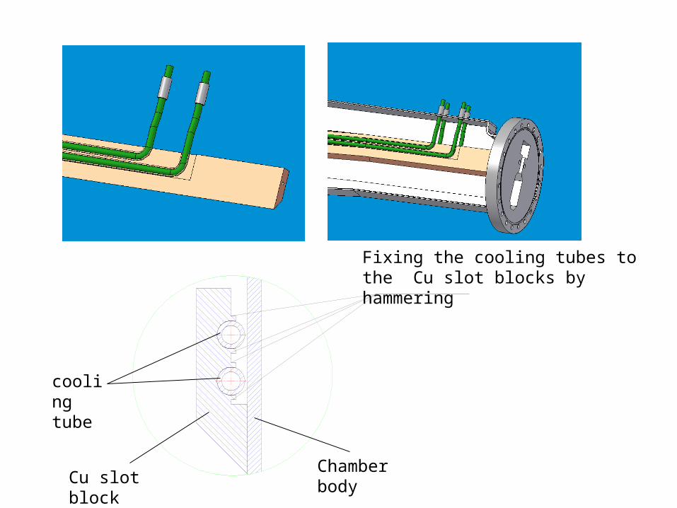
Fixing the cooling tubes to the Cu slot blocks by hammering
cooling tube
Chamber bodyCu slot block
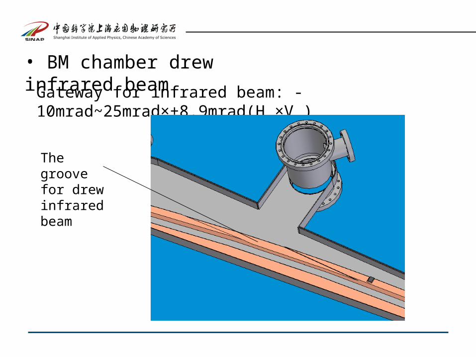
• BM chamber drew infrared beam
Gateway for infrared beam: -10mrad~25mrad×±8.9mrad(H ×V )
The groove for drew infrared beam
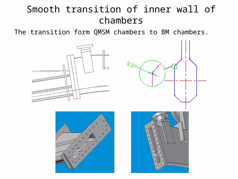
Smooth transition of inner wall of chambers
The transition form QMSM chambers to BM chambers.
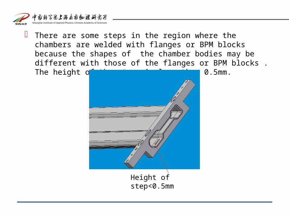
There are some steps in the region where the chambers are welded with flanges or BPM blocks because the shapes of the chamber bodies may be different with those of the flanges or BPM blocks . The height of the steps is less then 0.5mm.
Height of step<0.5mm
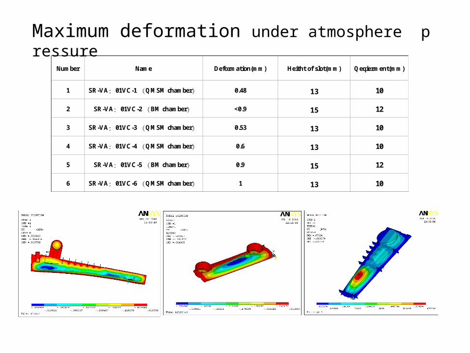
Maximum deformation under atmosphere pressure
Number Name Deformation(mm) Heitht of slot(mm) Qeqierment(mm)
1 SR-VA:01VC-1 (QMSM chamber) 0.48 13 10
2 SR-VA:01VC-2 (BM chamber) <0.9 15 12
3 SR-VA:01VC-3 (QMSM chamber) 0.53 13 10
4 SR-VA:01VC-4 (QMSM chamber) 0.6 13 10
5 SR-VA:01VC-5 (BM chamber) 0.9 15 12
6 SR-VA:01VC-6 (QMSM chamber) 1 13 10
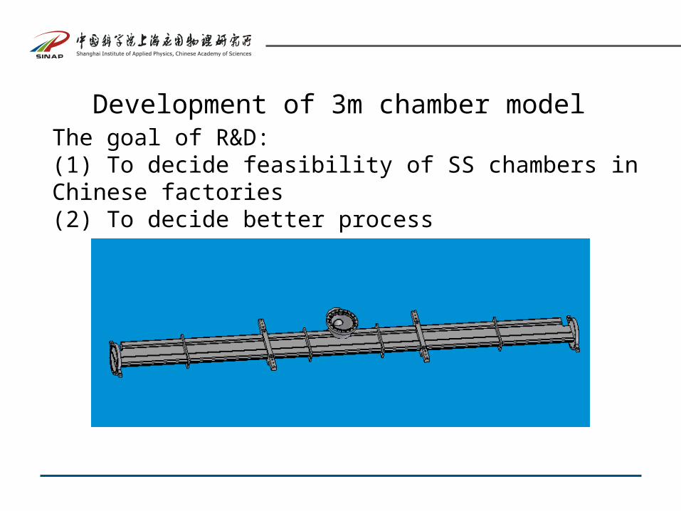
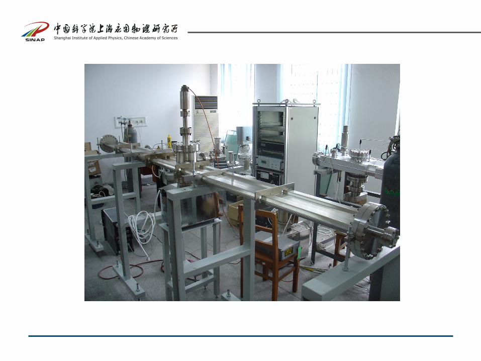
Development of 3m chamber modelThe goal of R&D: (1) To decide feasibility of SS chambers in Chinese factories(2) To decide better process
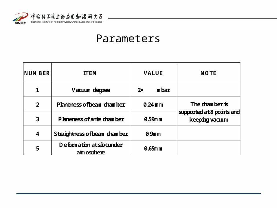
Parameters
NUMBER ITEM VALUE NOTE
1 Vacuum degree 2× mbar
2 Planeness of beam chamber 0.24 mm
3 Planeness of ante chamber 0.59mm
4 Straightness of beam chamber 0.9mm
5Deformation at slot under
atmosphere0.65mm
The chamber issupported at 8 points and
keeping vacuum
1010
Specification of the planenss and straightness of chambers
The specification:
Planenss: less then 0.5mm/each plane for 3m chamber
Straightness : less then 1mm for 6m chamber
Note: The supports in the BPM blocks do great contribution to the Planenss of the c
hambers, but do nothing to the Straightness of the chamber.
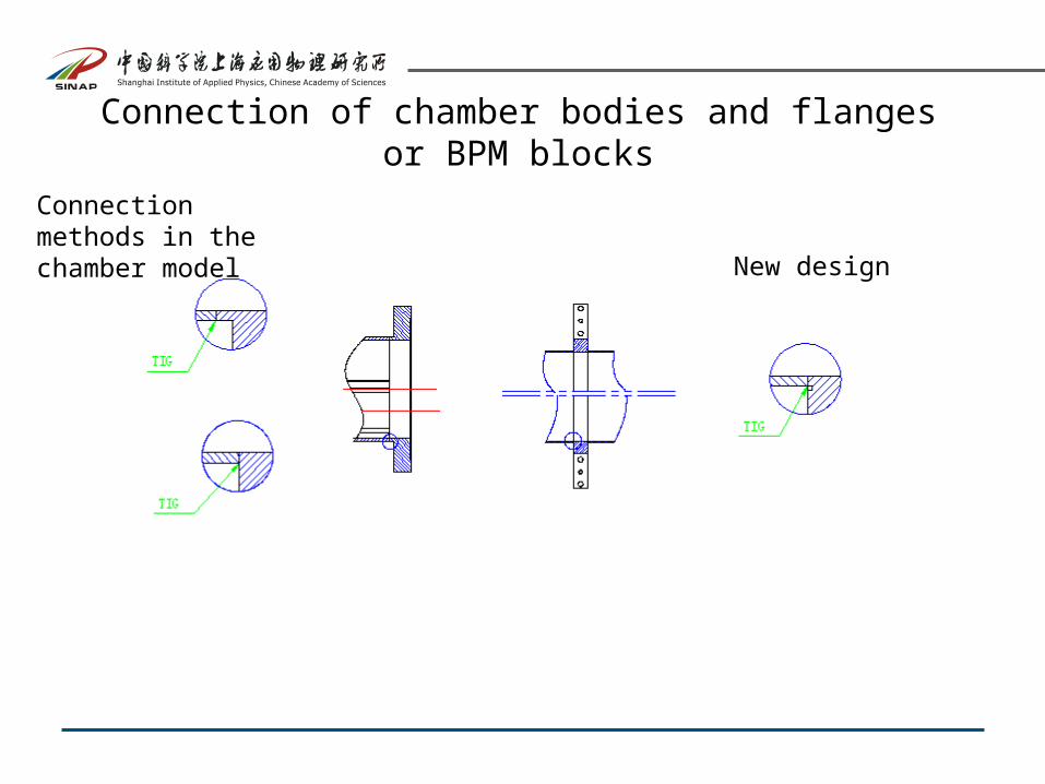
Connection of chamber bodies and flanges or BPM blocks
Connection methods in the chamber model New design
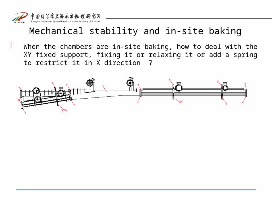
Mechanical stability and in-site baking
When the chambers are in-site baking, how to deal with the XY fixed support, fixing it or relaxing it or add a spring to restrict it in X direction ?
Primary thermal loads on chambers:
(1) Power from BMSR
(2) Power from absorbers because of fluorescence scattering
(3) Thermal load because of HOM lost
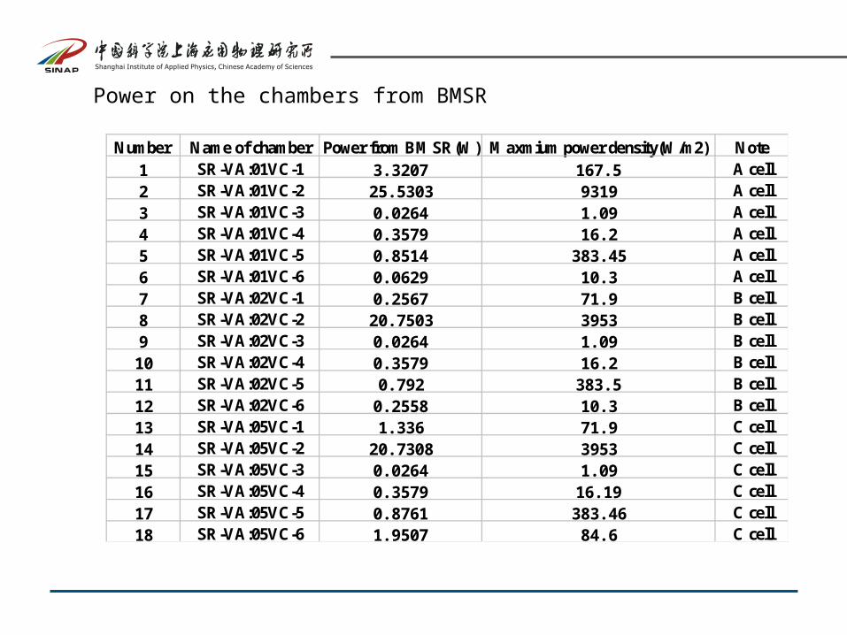
Power on the chambers from BMSR
Number Name of chamber Power from BMSR(W) Maxmium power density(W/m2) Note
1 SR-VA:01VC-1 3.3207 167.5 A cell
2 SR-VA:01VC-2 25.5303 9319 A cell
3 SR-VA:01VC-3 0.0264 1.09 A cell
4 SR-VA:01VC-4 0.3579 16.2 A cell
5 SR-VA:01VC-5 0.8514 383.45 A cell
6 SR-VA:01VC-6 0.0629 10.3 A cell
7 SR-VA:02VC-1 0.2567 71.9 B cell
8 SR-VA:02VC-2 20.7503 3953 B cell
9 SR-VA:02VC-3 0.0264 1.09 B cell
10 SR-VA:02VC-4 0.3579 16.2 B cell
11 SR-VA:02VC-5 0.792 383.5 B cell
12 SR-VA:02VC-6 0.2558 10.3 B cell
13 SR-VA:05VC-1 1.336 71.9 C cell
14 SR-VA:05VC-2 20.7308 3953 C cell
15 SR-VA:05VC-3 0.0264 1.09 C cell
16 SR-VA:05VC-4 0.3579 16.19 C cell
17 SR-VA:05VC-5 0.8761 383.46 C cell
18 SR-VA:05VC-6 1.9507 84.6 C cell
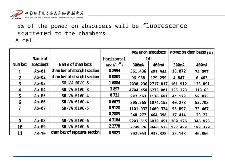
5% of the power on absorbers will be fluorescence scattered to the chambers .
300mA 400mA 300mA 400mA
1 Ab-01 chamber of straight section 0.2994 361. 436 481. 944 18. 072 24. 0972 Ab-02 chamber of straight section 0.0803 96. 938 129. 259 4. 847 6. 4633 Ab-03 SR-VA:01VC-3 1.6884 2038. 236 2717. 817 101. 912 135. 8914 Ab-04 SR-VA:01VC-3 3.897 4704. 458 6273. 001 235. 223 313. 655 Ab-05 SR-VA:01VC-4 0.731 882. 463 1176. 691 44. 123 58. 8356 Ab-06 SR-VA:01VC-4 0.6673 805. 565 1074. 153 40. 278 53. 708
0.9128 1101. 932 1469. 334 55. 097 73. 4670.2885 348. 277 464. 398 17. 414 23. 22
9 Ab-08 SR-VA:01VC-6 4.3104 5203. 515 6938. 451 260. 176 346. 92310 Ab-09 SR-VA:01VC-6 2.2778 2749. 76 3666. 575 137. 488 183. 32911 AB-10 chamber of separate section 0.5823 702. 953 937. 328 35. 148 46. 866
7 SR-VA:01VC-5
Power on chamberss (W)
Name of chambersNumberName of
absorbersHori zontalangel (O)
Power on absorbers
(W)
Ab-07
A cell
Thermal load because of HOM lost:
normal BPM: 4.12W
high precision BPM: 7.11W
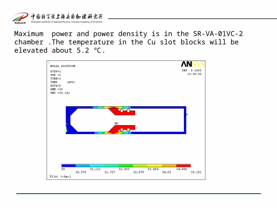
Maximum power and power density is in the SR-VA-01VC-2 chamber .The temperature in the Cu slot blocks will be elevated about 5.2 .℃
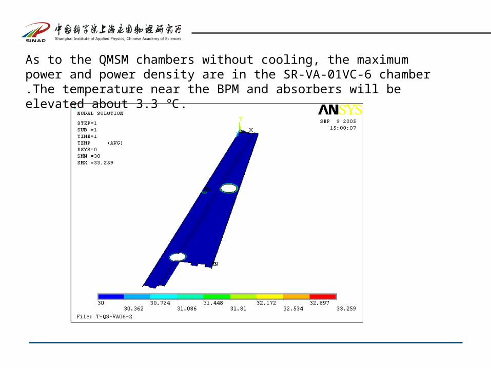
As to the QMSM chambers without cooling, the maximum power and power density are in the SR-VA-01VC-6 chamber .The temperature near the BPM and absorbers will be elevated about 3.3 .℃
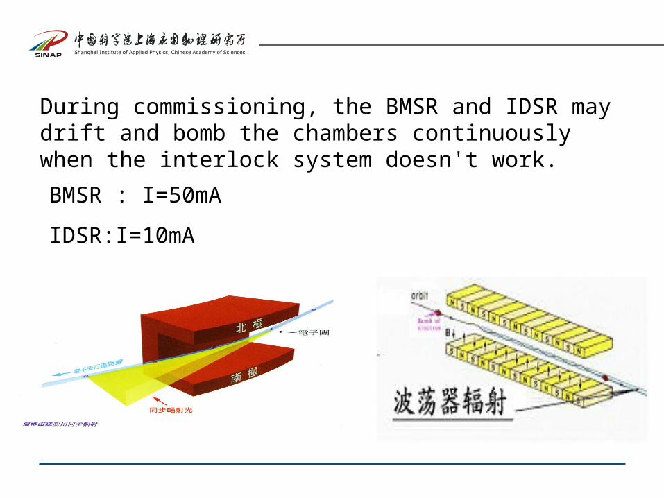
During commissioning, the BMSR and IDSR may drift and bomb the chambers continuously when the interlock system doesn't work.
BMSR : I=50mA
IDSR:I=10mA
(1) I=50mA, QMSM chamber without water cooling.
Chamber body Tmax= 160℃
Upstream flange Tmax= 167℃
(2) I=50mA, BM chamber with water cooling.
Cu slot blocks Tmax= 65.3℃
Cooling Water Tmax= 56.83℃
(3) I=10mA, IDSR+BMSR bomb BM chamber continuously with water cooling.
Cu slot blocks Tmax= 94.2℃
Cooling Water Tmax= 82.4 ℃
During normal running, the interlock system must work in a certain time when the BMSR and IDSR drift and bomb the chambers, otherwise the following accidents may be taken place:
(1) The temperature of the chambers will be elevated rapidly, which will lead to plenty of desorption.
(2) The the cooling water will reach the boiling point ,which will arose the libration of cooling tubes.
(3) The chamber will be melted.
Specification: Tmax=100 ℃
I=400mA, the QMSM chamber without cooling
After 0.4 s,
Chamber body: T= 100℃
! The interlock system must work in 0.4s when the beam drift seriously..
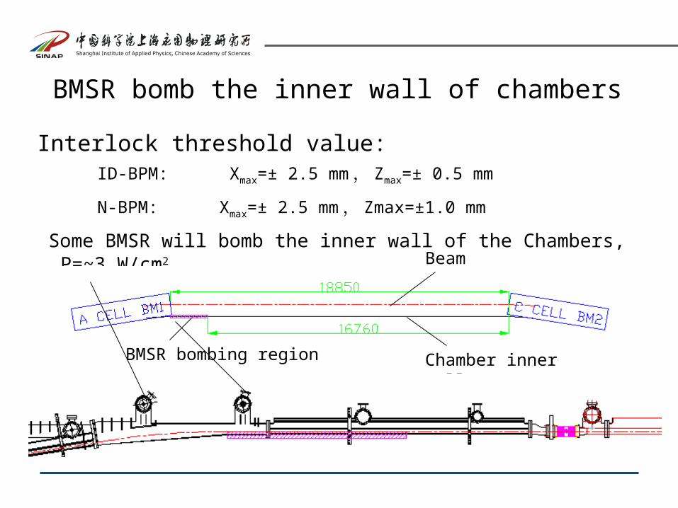
BMSR bomb the inner wall of chambers
Interlock threshold value:ID-BPM: Xmax=± 2.5 mm, Zmax=± 0.5 mm
N-BPM: Xmax=± 2.5 mm, Zmax=±1.0 mm
Some BMSR will bomb the inner wall of the Chambers, P=~3 W/cm2
Chamber inner wall
Beam
BMSR bombing region
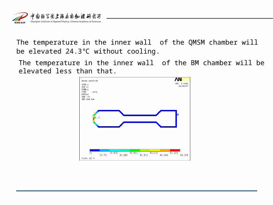
The temperature in the inner wall of the QMSM chamber will be elevated 24.3 ℃without cooling.
The temperature in the inner wall of the BM chamber will be elevated less than that.
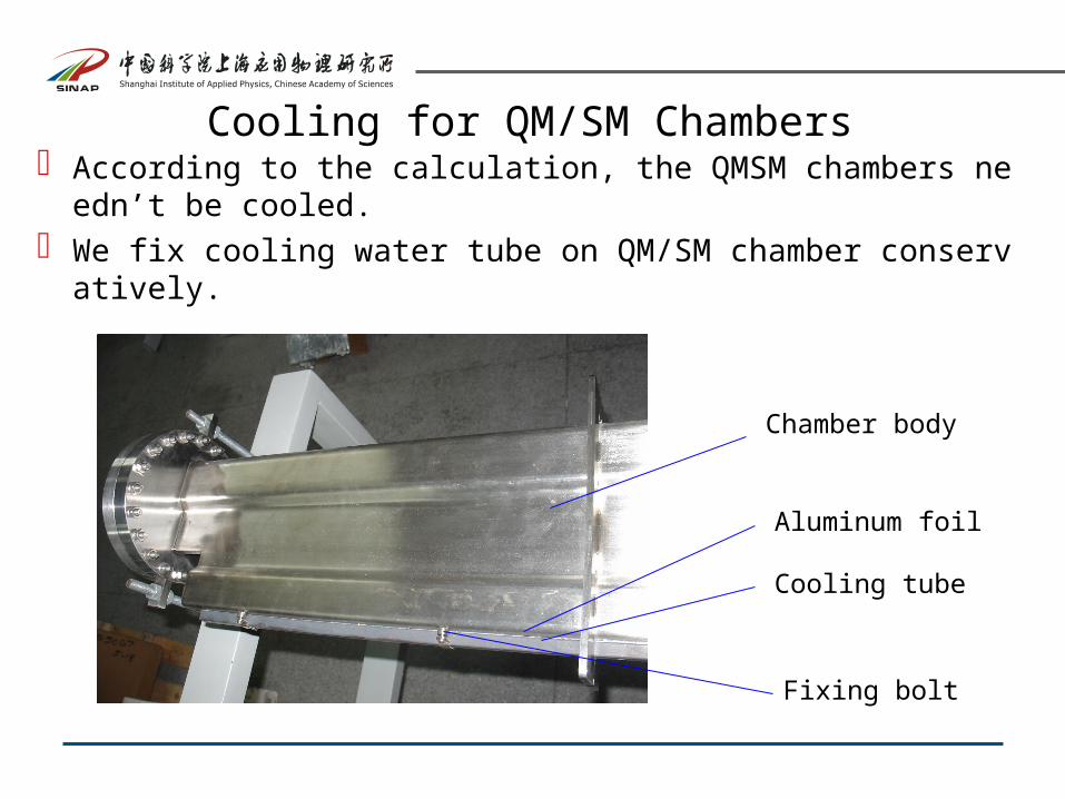
Cooling for QM/SM Chambers According to the calculation, the QMSM chambers needn’t be coo
led. We fix cooling water tube on QM/SM chamber conservatively.
Chamber body
Cooling tube
Aluminum foil
Fixing bolt
THANKS !


