Page 1
Design Of Vertical Pressure Vessel Using Pvelite Software
Binesh P Vyas Student, Mechanical
Department, VJTI,
Maharashtra, India,
R. M. Tayade
Professor, Mechanical
Department, VJTI,
Maharashtra, India,
Ankit D Kumbhani
Student, Mechanical
Department, VJTI,
Maharashtra, India,
Abstract
Pressure vessels are widely used in various industries. A vertical pressure vessel has been designed using graphical
based software named PVElite. For designing of vertical leg supported pressure vessel some input parameters like
volume, inside diameter, design pressure (either inside pressure or external pressure), temperature, material,
processing fluid. Etc. is required. PVElite gives thickness of shell, thickness of head, height of head, thickness of
nozzle, manhole. The high stresses at intersections are caused by discontinuity shear stresses and moments which
exist to maintain compatibility at the junctions. PVElite calculate this local stresses according to welding research
council (WRC) 107.
Key words: Vertical Pressure Vessel, Design using PVElite, Local stress analysis using PVElite.
1. INTRODUCTION
Pressure vessels are the container for fluid and gases
under high pressure. Due to high pressure, stresses
are induced in pressure vessel, if this stresses are
more than the permissible stresses then the failure of
pressure vessel occurs. So it is necessary to
manufacture pressure vessels under standard codes. A
code is a standard that has been adopted by one or
more governmental bodies and has the force of law,
or when it has been incorporated into a business
contract. Codes specify requirements of design,
fabrication, inspection and testing of pressure vessels.
A detailed study of various parts of pressure vessels
like shell, head support, flanges, nozzles etc. is
carried out according to rules of ASME code section
VIII, Division I. Due to mathematical calculation
designing of pressure vessel becomes tedious but by
using software like PVElite designing of pressure
vessel can be done easily. In the case of shell,
opening requiring reinforcement in vessel under
internal pressure the metal removed must be replaced
by the metal of reinforcement. In addition to
providing the area of reinforcement, adequate welds
must be provided to attach the metal of reinforcement
and the induced stresses must be evaluated.
2. ANALYSIS OF PRESSURE VESSEL USING
PVELITE AND DISCUSSION
2.1 Design condition
Design pressure: 0.245 MPa
Design temperature: 150 ċ
Material: SA240 M 316L
Corrosion allowance: Nil
process fluid : D M Water ( Non – Lethal )
Process fluid sp. Gravity: 1.00
Wind load/ snow load: Not applicable
Seismic load: AS per IS-1893, Zone III
2.2 Result and Discussion
In PVElite software we have to enter input data that
is required for pressure vessel element and then we
have to select its components like head, shell, pipe
and legs etc. And its calculate its o/p value like
thickness, shell/head height and all other result as
show in bellow. Pressure vessel contains fluid so
while designing we have to also consider static
pressure due to fluid. Static pressure is equal р * g *
h. Where, р= density of fluid, g= gravity and h=
height up to which vessel contain fluid.
PVElite also show analyzes result as follow:
Inside Corroded Head Depth [h]:
= L – Sqrt ((L - Di / 2) * (L + Di / 2 - 2 * r ) )
International Journal of Engineering Research & Technology (IJERT)
Vol. 2 Issue 3, March - 2013ISSN: 2278-0181
1www.ijert.org
IJERT
IJERT
Page 2
= 1000.00 –Sqrt ((1000.00 -1000.00 /2)*(1000.00
+1000.00 /2-2*100.00))
= 193.774 mm.
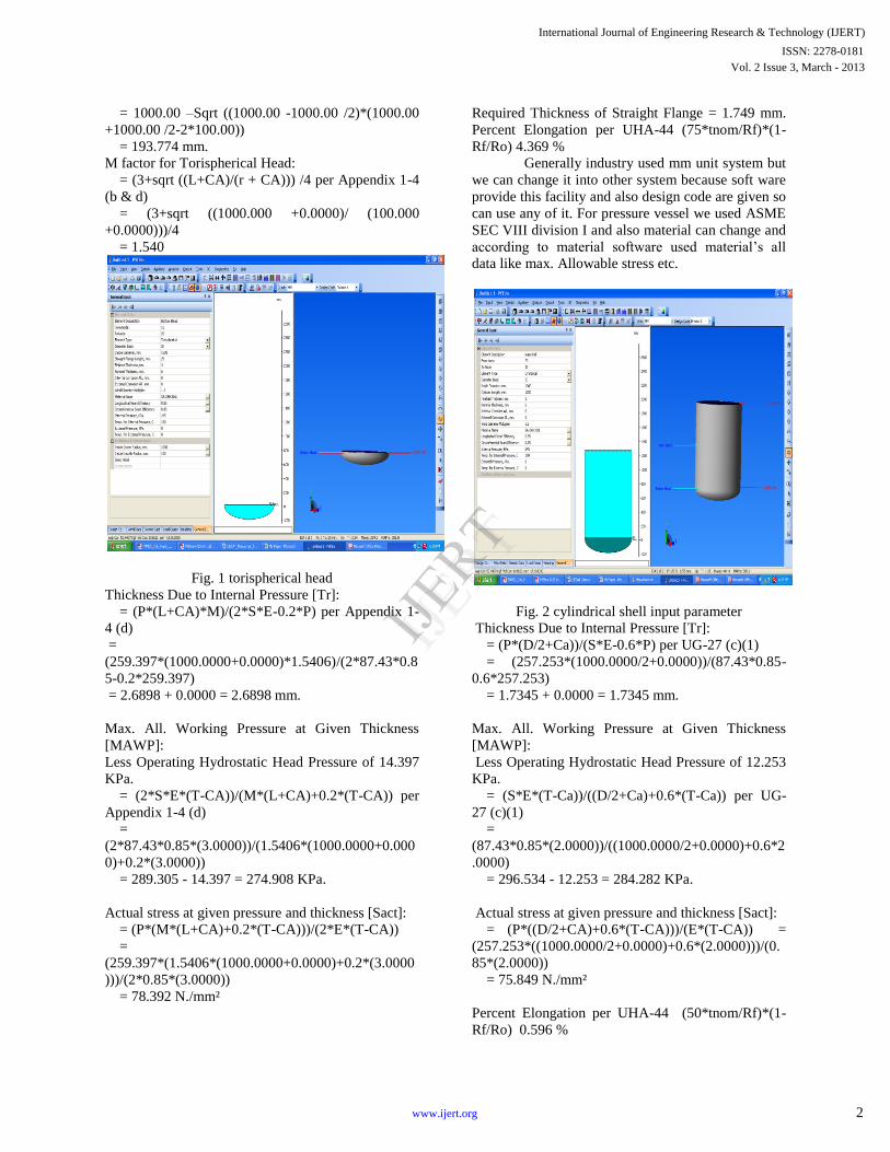
M factor for Torispherical Head:
= (3+sqrt ((L+CA)/(r + CA))) /4 per Appendix 1-4
(b & d)
= (3+sqrt ((1000.000 +0.0000)/ (100.000
+0.0000)))/4
= 1.540
Fig. 1 torispherical head
Thickness Due to Internal Pressure [Tr]:
= (P*(L+CA)*M)/(2*S*E-0.2*P) per Appendix 1-
4 (d)
=
(259.397*(1000.0000+0.0000)*1.5406)/(2*87.43*0.8
5-0.2*259.397)
= 2.6898 + 0.0000 = 2.6898 mm.
Max. All. Working Pressure at Given Thickness
[MAWP]:
Less Operating Hydrostatic Head Pressure of 14.397
KPa.
= (2*S*E*(T-CA))/(M*(L+CA)+0.2*(T-CA)) per
Appendix 1-4 (d)
=
(2*87.43*0.85*(3.0000))/(1.5406*(1000.0000+0.000
0)+0.2*(3.0000))
= 289.305 - 14.397 = 274.908 KPa.
Actual stress at given pressure and thickness [Sact]:
= (P*(M*(L+CA)+0.2*(T-CA)))/(2*E*(T-CA))
=
(259.397*(1.5406*(1000.0000+0.0000)+0.2*(3.0000
)))/(2*0.85*(3.0000))
= 78.392 N./mm²
Required Thickness of Straight Flange = 1.749 mm.
Percent Elongation per UHA-44 (75*tnom/Rf)*(1-
Rf/Ro) 4.369 %
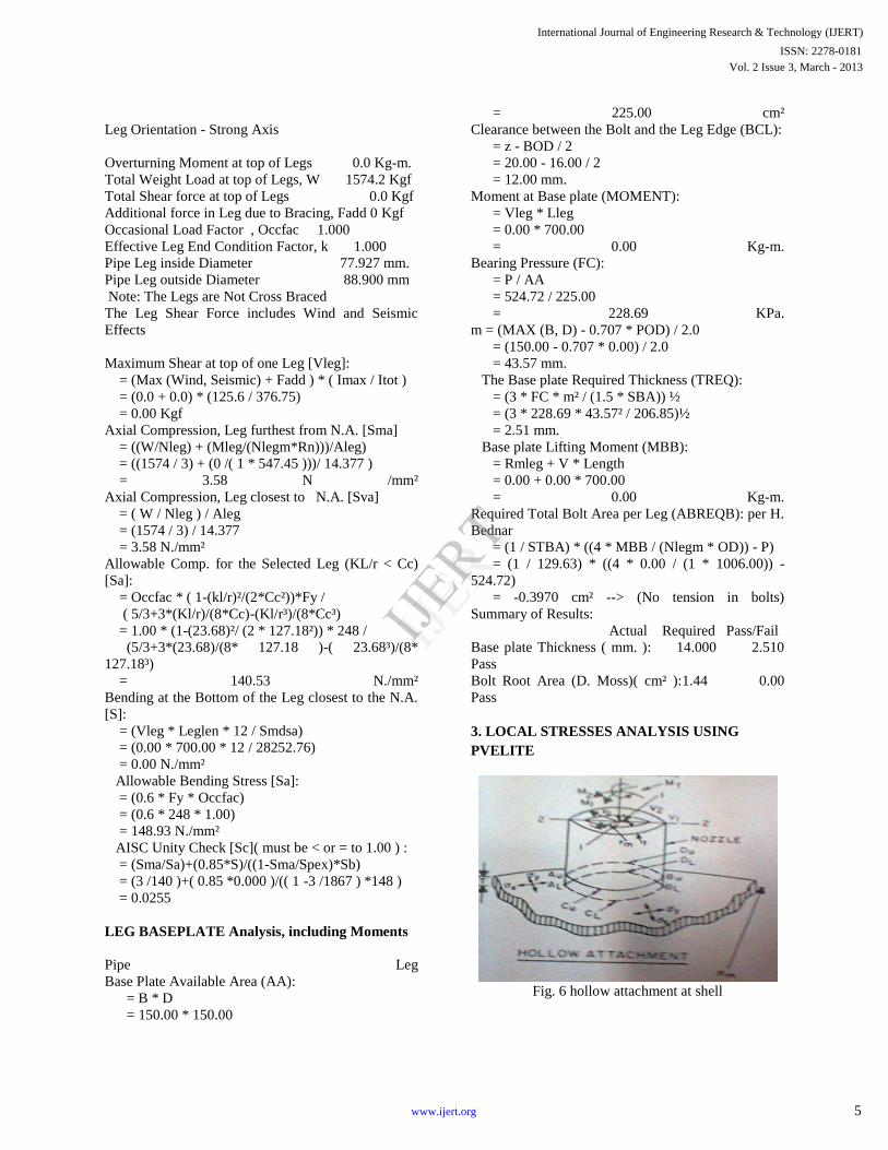
Generally industry used mm unit system but
we can change it into other system because soft ware
provide this facility and also design code are given so
can use any of it. For pressure vessel we used ASME
SEC VIII division I and also material can change and
according to material software used material’s all
data like max. Allowable stress etc.
Fig. 2 cylindrical shell input parameter
Thickness Due to Internal Pressure [Tr]:
= (P*(D/2+Ca))/(S*E-0.6*P) per UG-27 (c)(1)
= (257.253*(1000.0000/2+0.0000))/(87.43*0.85-
0.6*257.253)
= 1.7345 + 0.0000 = 1.7345 mm.
Max. All. Working Pressure at Given Thickness
[MAWP]:
Less Operating Hydrostatic Head Pressure of 12.253
KPa.
= (S*E*(T-Ca))/((D/2+Ca)+0.6*(T-Ca)) per UG-
27 (c)(1)
=
(87.43*0.85*(2.0000))/((1000.0000/2+0.0000)+0.6*2
.0000)
= 296.534 - 12.253 = 284.282 KPa.
Actual stress at given pressure and thickness [Sact]:
= (P*((D/2+CA)+0.6*(T-CA)))/(E*(T-CA)) =
(257.253*((1000.0000/2+0.0000)+0.6*(2.0000)))/(0.
85*(2.0000))
= 75.849 N./mm²
Percent Elongation per UHA-44 (50*tnom/Rf)*(1-
Rf/Ro) 0.596 %
International Journal of Engineering Research & Technology (IJERT)
Vol. 2 Issue 3, March - 2013ISSN: 2278-0181
2www.ijert.org
IJERT
IJERT
Page 3
In this pressure vessel there are four nozzles
including manhole. Here I show only one manhole’s
input parameter and its calculation given by PVElite.
Here I selectee nozzle with RF pad and input all
parameter including nozzle orientation.
Fig. 3 manhole M input parameter
Nozzle Sketch | |
| |
| |
| |
__________/| |
____/|__________\| |
| \ | |
| \ | |
|________________\|__|
Fig. 4 Insert Nozzle with Pad, no inside projection
NOZZLE CALCULATION, Description: man
hole M
ASME Code, Section VIII, Division 1, 2007, UG-37
to UG-45
Actual Nozzle Inside Diameter Used in Calculation
428.650 mm.
Actual Nozzle Thickness Used in Calculation
14.275 mm.
Nozzle input data check completed without errors.
Reqd thickness per UG-37(a)of Torispherical Head,
Tr [Int. Press]
= (P*(L+CA)*M)/(2*S*E-0.2*P) App. 1-4 (d)
= (245.00*(1000.0000+0.0000)*1.00)/(
2*87*1.00-0.2*245.00)
= 1.4016 mm.
Reqd thickness per UG-37(a)of Nozzle Wall, Trn
[Int. Press]
= (P*(D/2+CA))/(S*E-0.6*P) per UG-27 (c)(1)
= (245.00*(428.6504/2+0.0000))/(87*1.00-
0.6*245.00)
= 0.6016 mm.
UG-40, Thickness and Diameter Limit Results :
[Int. Press]
Effective material diameter limit, Dl 857.3008 mm.
Effective material thickness limit, no pad Tlnp
7.5000 mm.
Effective material thickness limit, pad side Tlwp
7.5000 mm.
Results of Nozzle Reinforcement Area
Calculations: AREA AVAILABLE, A1 to A5
Area Required , Ar 6.008 cm²
Area in Shell, A1 6.852 cm²
Area in Nozzle Wall, A2 = 2.051 cm²
Area in Inward Nozzle, A3 = 0.000 cm²
Area in Welds,A4 = 0.407 cm²
Area in Pad , A5 = 8.568 cm²
TOTAL AREA AVAILABLE, Atot = 17.878 cm²
The Internal Pressure Case Governs the Analysis.
Nozzle Angle Used in Area Calculations
90.00 Degs.
The area available without a pad is Sufficient.
The area available with the given pad is Sufficient.
Reinforcement Area Required for Nozzle [Ar]:
= (Dlr*Tr+2*Thk*Tr*(1-fr1)) UG-37(c)
= (428.6504*1.4016+2*(14.2748-
0.0000)*1.4016*(1-1.0000))
= 6.008 cm²
Areas per UG-37.1 but with DL = Diameter Limit,
DLR = Corroded ID:
Area Available in Shell [A1]:
= (DL-Dlr)*(ES*(T-Cas)-Tr)-2*(Thk-
Can)*(ES*(T-Cas)-Tr)*(1-fr1)
= (857.301-428.650)*(1.00*(3.0000-0.000)-
1.402)-2*(14.275-0.000)
*(1.00*(3.0000-0.0000)-1.4016)*(1-1.0000)
= 6.852 cm²
Area Available in Nozzle Wall, no Pad [A2np]:
= ( 2 * min(Tlnp,ho) ) * ( Thk - Can - Trn ) * fr2
= ( 2 * min(7.50 ,63.60 ) ) * ( 14.27 - 0.00 - 0.60 )
* 1.0000 )
= 2.051 cm²
International Journal of Engineering Research & Technology (IJERT)
Vol. 2 Issue 3, March - 2013ISSN: 2278-0181
3www.ijert.org
IJERT
IJERT
Page 4
Area Available in Nozzle Wall, with Pad [A2wp]:
= ( 2 * Tlwp)*( Thk - Can - Trn )* fr2
= ( 2 * 7.5000 ) * ( 14.2748 - 0.0000 - 0.6016 ) *
1.0000
Area Available in Welds, no Pad [A4np]:
= Wo² * fr2 + ( Wi-Can/0.707 )² * fr2
= 6.0000² * 1.0000 + (0.0000)² * 1.0000
= 0.360 cm²
Area Available in Welds, with Pad [A4wp]:
= (Wo² - Ar Lost)*Fr3+((Wi-Can/0.707)² - Ar
Lost)*Fr2 + Wp²*Fr4
= (0.1575) * 1.00 + (0.0000) * 1.00 + 25.0000² *
1.00
= 0.407 cm²
Area Available in Pad [A5]:
= (min (Dp, DL)-(Nozzle OD))*(min (Tp, Tlwp,
Te))*fr4
= (600.0000 - 457.2000) * 6.0000 * 1.00
= 8.568 cm²
UG-45 Minimum Nozzle Neck Thickness
Requirement: [Int. Press.] Wall Thickness per UG45 (a), tra = 0.6016 mm.
Wall Thickness per UG16 (b), tr16b = 1.5875 mm.
Wall Thickness per UG45 (b) (1), trb1 = 2.1592 mm.
Check UG16 (b) Min. Thickness, trb1 = Max (trb1,
tr16b) = 2.1592 mm.
Std. Wall Pipe per UG45 (b)(4), trb4 = 8.3344 mm.
Wall Thickness per UG45 (b),
trb = Min(trb1, trb4) = 2.1592 mm.
Final Required Thickness, tr45 = Max (tra, trb) =
2.1592 mm.
Available Nozzle Neck Thickness = .875 *
14.2748 = 12.4905 mm. --> OK
M.A.W.P. Results for this Nozzle (Based on Areas)
at this Location Approximate M.A.W.P. for given
geometry 289.305 KPa.
Weld Size Calculations, Description: man hole M
Intermediate Calc. for nozzle/shell Welds Tmin
6.0000 mm. Intermediate Calc. for pad/shell Welds
Tmin Pad 6.0000 mm.
Results Per UW-16.1: Required Thickness Actual Thickness
Nozzle Weld4.2000 = 0.7 *TMIN 4.2420 = 0.7 *
WO mm.
Pad Weld 3.0000 = 0.5*Tmin Pad 3.5350 = 0.7 * WP
mm.
The Drop for this Nozzle is: 26.3982 mm.
The Cut Length for this Nozzle is, Drop + Ho + H +
T: 93.0000 mm.
Manhole or hand hole is required for
inspection or cleaning and repair work and which
one is selected is depend on pressure vessel diameter
.As per UG-46 (f) (1) vessel less than 450 mm &
over 300 mm I.D should have at least two hand hole
and I.D more than it should have man hole.
According to UG-46 (g) (1) a circular manhole shall
not be less than 400 mm I.D. Below Figure show
input parameter and analysis of leg support with base
plate.
Fig. 5 Pipe Leg support input parameter
RESULTS FOR LEGS: Hydro Test Case
Description: LEGS
Legs attached to: bottom dishend
Section Properties: Circular Steel Pipe: PIPE
India ISI Structural Steel Data
Leg Length from Attachment to Base
Leglen 700.000 mm.
Number of Legs Nleg 3
Cross Sectional Area for PIPE Aleg 14.377 cm²
Section Inertia (strong axis) 125.583 cm**4
Section Inertia (weak axis) 125.583 cm**4
Section Modulus (strong axis) 28252.760 mm.³
Section Modulus (weak axis) 28252.760 mm.³
Radius of Gyration ( strong axis ) 29.555 mm.
Radius of Gyration (weak axis ) 29.555 mm.
International Journal of Engineering Research & Technology (IJERT)
Vol. 2 Issue 3, March - 2013ISSN: 2278-0181
4www.ijert.org
IJERT
IJERT
Page 5
Leg Orientation - Strong Axis
Overturning Moment at top of Legs 0.0 Kg-m.
Total Weight Load at top of Legs, W 1574.2 Kgf
Total Shear force at top of Legs 0.0 Kgf
Additional force in Leg due to Bracing, Fadd 0 Kgf
Occasional Load Factor , Occfac 1.000
Effective Leg End Condition Factor, k 1.000
Pipe Leg inside Diameter 77.927 mm.
Pipe Leg outside Diameter 88.900 mm
Note: The Legs are Not Cross Braced
The Leg Shear Force includes Wind and Seismic
Effects
Maximum Shear at top of one Leg [Vleg]:
= (Max (Wind, Seismic) + Fadd ) * ( Imax / Itot )
= (0.0 + 0.0) * (125.6 / 376.75)
= 0.00 Kgf
Axial Compression, Leg furthest from N.A. [Sma]
= ((W/Nleg) + (Mleg/(Nlegm*Rn)))/Aleg)
= ((1574 / 3) + (0 /( 1 * 547.45 )))/ 14.377 )
= 3.58 N /mm²
Axial Compression, Leg closest to N.A. [Sva]
= ( W / Nleg ) / Aleg
= (1574 / 3) / 14.377
= 3.58 N./mm²
Allowable Comp. for the Selected Leg (KL/r < Cc)
[Sa]:
= Occfac * ( 1-(kl/r)²/(2*Cc²))*Fy /
( 5/3+3*(Kl/r)/(8*Cc)-(Kl/r³)/(8*Cc³)
= 1.00 * (1-(23.68)²/ (2 * 127.18²)) * 248 /
(5/3+3*(23.68)/(8* 127.18 )-( 23.68³)/(8*
127.18³)
= 140.53 N./mm²
Bending at the Bottom of the Leg closest to the N.A.
[S]:
= (Vleg * Leglen * 12 / Smdsa)
= (0.00 * 700.00 * 12 / 28252.76)
= 0.00 N./mm²
Allowable Bending Stress [Sa]:
= (0.6 * Fy * Occfac)
= (0.6 * 248 * 1.00)
= 148.93 N./mm²
AISC Unity Check [Sc]( must be < or = to 1.00 ) :
= (Sma/Sa)+(0.85*S)/((1-Sma/Spex)*Sb)
= (3 /140 )+( 0.85 *0.000 )/(( 1 -3 /1867 ) *148 )
= 0.0255
LEG BASEPLATE Analysis, including Moments
Pipe Leg
Base Plate Available Area (AA):
= B * D
= 150.00 * 150.00
= 225.00 cm²
Clearance between the Bolt and the Leg Edge (BCL):
= z - BOD / 2
= 20.00 - 16.00 / 2
= 12.00 mm.
Moment at Base plate (MOMENT):
= Vleg * Lleg
= 0.00 * 700.00
= 0.00 Kg-m.
Bearing Pressure (FC):
= P / AA
= 524.72 / 225.00
= 228.69 KPa.
m = (MAX (B, D) - 0.707 * POD) / 2.0
= (150.00 - 0.707 * 0.00) / 2.0
= 43.57 mm.
The Base plate Required Thickness (TREQ):
= (3 * FC * m² / (1.5 * SBA)) ½
= (3 * 228.69 * 43.57² / 206.85)½
= 2.51 mm.
Base plate Lifting Moment (MBB):
= Rmleg + V * Length
= 0.00 + 0.00 * 700.00
= 0.00 Kg-m.
Required Total Bolt Area per Leg (ABREQB): per H.
Bednar
= (1 / STBA) * ((4 * MBB / (Nlegm * OD)) - P)
= (1 / 129.63) * ((4 * 0.00 / (1 * 1006.00)) -
524.72)
= -0.3970 cm² --> (No tension in bolts)
Summary of Results:
Actual Required Pass/Fail
Base plate Thickness ( mm. ): 14.000 2.510
Pass
Bolt Root Area (D. Moss)( cm² ):1.44 0.00
Pass
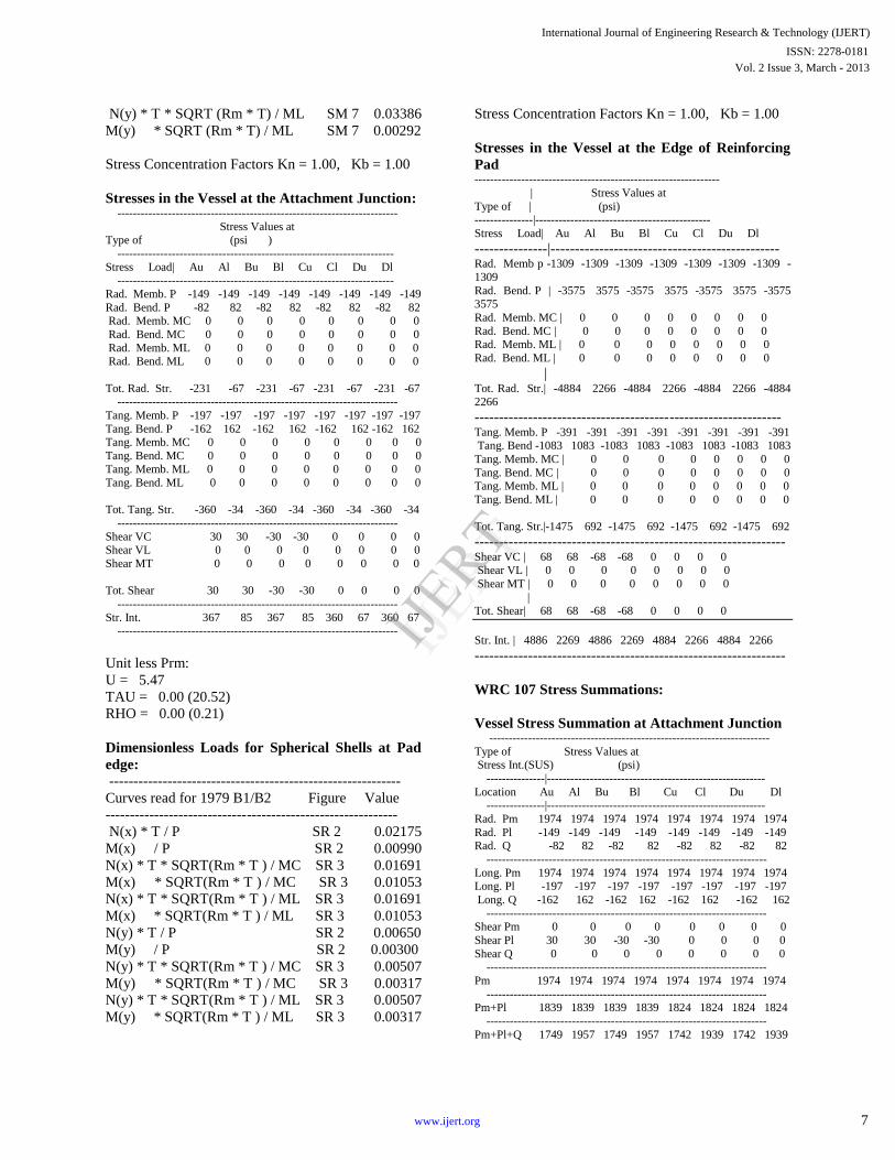
3. LOCAL STRESSES ANALYSIS USING
PVELITE
Fig. 6 hollow attachment at shell
International Journal of Engineering Research & Technology (IJERT)
Vol. 2 Issue 3, March - 2013ISSN: 2278-0181
5www.ijert.org
IJERT
IJERT
Page 6
When pressure vessels have to be connected
to a piping system, the attachment of nozzles to the
crown becomes inevitable. There have been
numerous detailed analyses of torispherical shells
with radial nozzles, being subjected to various
loadings. The nozzle has been singled out as a
potential source of weakness in the sense that high
stresses occur here. If stresses are within the limit
than PVElite shown joint is safe. Here only radial
load and shear force V2 is consider and shear force
V1 is not consider because of unidirectional loading
and moment doe to this force are not excepted in this
example. Local stress analysis of manhole’s input
parameter window is shown below.
Fig.7 Local stress analysis of man hole
Input Echo, WRC107 Item 1,
Description: manhole M
Diameter Basis for Vessel Vbasis ID
Cylindrical or Spherical Vessel Cylsph Spherical
Corrosion Allowance for Vessel Cas 0.0000 in.
Vessel Diameter Dv 78.740 in.
Vessel Thickness Tv 0.118 in.
Design Temperature 301.98 F
Vessel Material SA-240 316L
Vessel Cold S.I. Allowable Smc 16700.00 psi
Vessel Hot S.I. Allowable Smh 12680.24 psi
Attachment Type Type Round
WRC107 Attachment Classification, Holsol Hollow
Diameter Basis for Nozzle Nbasis ID
Corrosion Allowance for Nozzle Can 0.0000 in.
Nozzle Diameter Dn 16.876 in.
Nozzle Thickness Tn 0.562 in.
Nozzle Material SA-312 TP316L
Nozzle Cold S.I. Allowable SNmc 16700.00 psi
Nozzle Hot S.I. Allowable SNmh 12680.24 psi
Thickness of Reinforcing Pad Tpad 0.236 in.
Diameter of Reinforcing Pad Dpad 23.622 in.
Design Internal Pressure Dp 35.535 psig
Include Pressure Thrust No
External Forces and Moments in WRC 107
Convention:
Radial Load (SUS) P 839.7 lb.
Longitudinal Shear (SUS) (Vl) V1 0.0 lb.
Circumferential Shear (SUS) (Vc) V2 301.9 lb.
Circumferential Moment (SUS) (Mc) M1 0.0 ft.lb.
Longitudinal Moment (SUS) (Ml) M2 0.0 ft.lb.
Torsional Moment (SUS) Mt 0.0 ft.lb.
Use Interactive Control No
WRC107 Version Version March
1979 (B1 & B2)
Include Pressure Stress Indices per Div. 2 No
Compute Pressure Stress per WRC-368 No
WRC 107 Stress Calculation for Sustained loads:
Radial Load P 839.7 lb.
Circumferential Shear (VC) V2 301.9 lb.
Longitudinal Shear (VL) V1 0.0 lb.
Circumferential Moment (MC) M1 0.0 ft.lb.
Longitudinal Moment (ML) M2 0.0 ft.lb.
Torsional Moment MT 0.0 ft.lb.
Dimensionless Parameter:
U = 2.40
TAU = 15.51
RHO = 4.00 (0.63)
Below all value taken from respective figure than
given in welding Research council bulletin 107. By
using PVElite software its easy to get its value and
reduce time otherwise we have to do little iteration
and its tedious work.
Dimensionless Loads for Spherical Shells at
Attachment Junction:
------------------------------------------------------------
Curves read for 1979 B1/B2 Figure Value
Location
------------------------------------------------------------
N(x) * T / P SP 7 0.02237
M(x) / P SP 7 0.00205
N(x)*T *SQRT(Rm * T) /MC SM 7 0.02019
M(x) *SQRT(Rm * T ) /MC SM 7 0.00160
N(x) * T *SQRT(Rm * T) /ML SM 7 0.02019
M(x) *SQRT(Rm * T ) /ML SM 7 0.00160
N(y) * T / P SP 7 0.02957
M(y) / P SP 7 0.00406
N(y) * T * SQRT (Rm * T ) / MC SM 7 0.03386
M(y) * SQRT (Rm * T) / MC SM 7 0.00292
International Journal of Engineering Research & Technology (IJERT)
Vol. 2 Issue 3, March - 2013ISSN: 2278-0181
6www.ijert.org
IJERT
IJERT
Page 7
N(y) * T * SQRT (Rm * T) / ML SM 7 0.03386
M(y) * SQRT (Rm * T) / ML SM 7 0.00292
Stress Concentration Factors Kn = 1.00, Kb = 1.00
Stresses in the Vessel at the Attachment Junction: ------------------------------------------------------------------------
Stress Values at Type of (psi )
-----------------------------------------------------------------------
Stress Load| Au Al Bu Bl Cu Cl Du Dl -----------------------------------------------------------------------
Rad. Memb. P -149 -149 -149 -149 -149 -149 -149 -149
Rad. Bend. P -82 82 -82 82 -82 82 -82 82 Rad. Memb. MC 0 0 0 0 0 0 0 0
Rad. Bend. MC 0 0 0 0 0 0 0 0
Rad. Memb. ML 0 0 0 0 0 0 0 0 Rad. Bend. ML 0 0 0 0 0 0 0 0
Tot. Rad. Str. -231 -67 -231 -67 -231 -67 -231 -67 ------------------------------------------------------------------------
Tang. Memb. P -197 -197 -197 -197 -197 -197 -197 -197
Tang. Bend. P -162 162 -162 162 -162 162 -162 162 Tang. Memb. MC 0 0 0 0 0 0 0 0
Tang. Bend. MC 0 0 0 0 0 0 0 0 Tang. Memb. ML 0 0 0 0 0 0 0 0
Tang. Bend. ML 0 0 0 0 0 0 0 0
Tot. Tang. Str. -360 -34 -360 -34 -360 -34 -360 -34
------------------------------------------------------------------------
Shear VC 30 30 -30 -30 0 0 0 0 Shear VL 0 0 0 0 0 0 0 0
Shear MT 0 0 0 0 0 0 0 0
Tot. Shear 30 30 -30 -30 0 0 0 0
------------------------------------------------------------------------
Str. Int. 367 85 367 85 360 67 360 67 ------------------------------------------------------------------------
Unit less Prm:
U = 5.47
TAU = 0.00 (20.52)
RHO = 0.00 (0.21)
Dimensionless Loads for Spherical Shells at Pad
edge:
------------------------------------------------------------
Curves read for 1979 B1/B2 Figure Value
------------------------------------------------------------
N(x) * T / P SR 2 0.02175
M(x) / P SR 2 0.00990
N(x) * T * SQRT(Rm * T ) / MC SR 3 0.01691
M(x) * SQRT(Rm * T ) / MC SR 3 0.01053
N(x) * T * SQRT(Rm * T ) / ML SR 3 0.01691
M(x) * SQRT(Rm * T ) / ML SR 3 0.01053
N(y) * T / P SR 2 0.00650
M(y) / P SR 2 0.00300
N(y) * T * SQRT(Rm * T ) / MC SR 3 0.00507
M(y) * SQRT(Rm * T ) / MC SR 3 0.00317
N(y) * T * SQRT(Rm * T ) / ML SR 3 0.00507
M(y) * SQRT(Rm * T ) / ML SR 3 0.00317
Stress Concentration Factors Kn = 1.00, Kb = 1.00
Stresses in the Vessel at the Edge of Reinforcing
Pad ---------------------------------------------------------------
| Stress Values at
Type of | (psi) ---------------|---------------------------------------------
Stress Load| Au Al Bu Bl Cu Cl Du Dl
---------------|----------------------------------------------- Rad. Memb p -1309 -1309 -1309 -1309 -1309 -1309 -1309 -
1309
Rad. Bend. P | -3575 3575 -3575 3575 -3575 3575 -3575 3575
Rad. Memb. MC | 0 0 0 0 0 0 0 0
Rad. Bend. MC | 0 0 0 0 0 0 0 0 Rad. Memb. ML | 0 0 0 0 0 0 0 0
Rad. Bend. ML | 0 0 0 0 0 0 0 0
| Tot. Rad. Str.| -4884 2266 -4884 2266 -4884 2266 -4884 2266
---------------------------------------------------------------Tang. Memb. P -391 -391 -391 -391 -391 -391 -391 -391 Tang. Bend -1083 1083 -1083 1083 -1083 1083 -1083 1083
Tang. Memb. MC | 0 0 0 0 0 0 0 0
Tang. Bend. MC | 0 0 0 0 0 0 0 0 Tang. Memb. ML | 0 0 0 0 0 0 0 0
Tang. Bend. ML | 0 0 0 0 0 0 0 0
Tot. Tang. Str.|-1475 692 -1475 692 -1475 692 -1475 692
---------------------------------------------------------------- Shear VC | 68 68 -68 -68 0 0 0 0 Shear VL | 0 0 0 0 0 0 0 0
Shear MT | 0 0 0 0 0 0 0 0
|
Tot. Shear| 68 68 -68 -68 0 0 0 0
Str. Int. | 4886 2269 4886 2269 4884 2266 4884 2266
----------------------------------------------------------------
WRC 107 Stress Summations:
Vessel Stress Summation at Attachment Junction ------------------------------------------------------------------------Type of Stress Values at Stress Int.(SUS) (psi)
---------------|--------------------------------------------------------
Location Au Al Bu Bl Cu Cl Du Dl ---------------|--------------------------------------------------------
Rad. Pm 1974 1974 1974 1974 1974 1974 1974 1974
Rad. Pl -149 -149 -149 -149 -149 -149 -149 -149 Rad. Q -82 82 -82 82 -82 82 -82 82
------------------------------------------------------------------------
Long. Pm 1974 1974 1974 1974 1974 1974 1974 1974 Long. Pl -197 -197 -197 -197 -197 -197 -197 -197
Long. Q -162 162 -162 162 -162 162 -162 162
------------------------------------------------------------------------Shear Pm 0 0 0 0 0 0 0 0
Shear Pl 30 30 -30 -30 0 0 0 0
Shear Q 0 0 0 0 0 0 0 0 ------------------------------------------------------------------------
Pm 1974 1974 1974 1974 1974 1974 1974 1974
------------------------------------------------------------------------ Pm+Pl 1839 1839 1839 1839 1824 1824 1824 1824
------------------------------------------------------------------------
Pm+Pl+Q 1749 1957 1749 1957 1742 1939 1742 1939
International Journal of Engineering Research & Technology (IJERT)
Vol. 2 Issue 3, March - 2013ISSN: 2278-0181
7www.ijert.org
IJERT
IJERT
Page 8
------------------------------------------------------------------------
Type of Max. S.I. S.I. Allowable Result Stress Int. psi
------------------------------------------------------------------------
Pm (SUS) 1974 12680 Passed Pm+Pl (SUS) 1839 19020 Passed
Pm+Pl+Q (TOTAL) 1957 44070 Passed
------------------------------------------------------------------------
WRC 107 Stress Summations:
Vessel Stress Summation at Reinforcing Pad Edge ------------------------------------------------------------------------Type of Stress Values at
Stress Int. (psi ) ---------------|--------------------------------------------------------
Location | Au Al Bu Bl Cu Cl Du Dl
---------------|-------------------------------------------------------- Rad. Pm 5922 5922 5922 5922 5922 5922 5922 5922
Rad. Pl -1309 -1309 -1309 -1309 -1309 -1309 -1309 -1309
Rad. Q -3575 3575 -3575 3575 -3575 3575 -3575 3575 ------------------------------------------------------------------------
Long. Pm 5922 5922 5922 5922 5922 5922 5922 5922
Long. Pl -391 -391 -391 -391 -391 -391 -391 -391 Long. Q -1083 1083 -1083 1083 -1083 1083 -1083 1083
------------------------------------------------------------------------
Shear Pm 0 0 0 0 0 0 0 0 Shear Pl 68 68 -68 -68 0 0 0 0
Shear Q | 0 0 0 0 0 0 0 0
------------------------------------------------------------------------ Pm 5922 5922 5922 5922 5922 5922 5922 5922
------------------------------------------------------------Pm+Pl 5536 5536 5536 5536 5531 5531 5531 5531 ------------------------------------------------------------------------
Pm+Pl+Q 4448 8192 4448 8192 4447 8189 4447 8189
------------------------------------------------------------------------ -----------------------------------------------------------------------
Type of Max. S.I. S.I. Allowable Result
Stress Int. psi
---------------|--------------------------------------------------------
Pm (SUS) 5922 12680 Passed
Pm+Pl (SUS) 5536 19020 Passed Pm+Pl+Q (TOTAL) 8192 44070 Passed
------------------------------------------------------------------------
4. Conclusion
Design of pressure vessel by using PVElite gives
accurate analysis result and also reduces time.
Further research need to explore environmental
parameter such as earthquake, thermal load,
fluctuation load and so on. Moreover dynamic
processes in design need to employ for optimization
instead of fixing the input parameter. High stresses
occurred at intersection of head and nozzle Welding
Research council (WRC) bulletin gives formulation
for calculating this stresses.
5. References (1) Stress analysis of torispherical shell with radial
nozzle by Amran Ayob Faculty of Mechanical
engineering, University Teknologi Malaysia,
81310 Skudai, Johor.
(2) F.A. Leckie and R.K. Penny, "Stress
Concentration Factors for the Stresses at Nozzle
Intersections in Pressure Vessels", Welding
Research Council, Bulletin 90, 1963.
(3) R.K.Penny and F.A. Leckie, "Solution for the
Stresses at Nozzles in Pressure Vessels",
Welding Research Council, Bulletin 90, 1963.
(4) ASME Boiler & Pressure Vessel Code: Rules for
Construction of Pressure vessels, (ASME VIII),
Division1, 2007
(5) Moss, Dennis. Pressure Vessel Design Manual.
Third Edition, Gulf Professional Publishing Inc,
Burlington, 2004. (6) Megyesy, Eugene F., Pressure Vessel Handbook.
Eleventh Edition, Pressure Vessel Publishing Inc.
Tulsa., Oklahoma. 2001.
(7) R. Farr, James. And H. Jawad, Maan, Guide Book for
the Design of ASME Section VIII Pressure Vessel,
ASME Press, New York, 2001.
(8) Jimit Vyas and Mahavir Solanski, Design and
Analysis of Pressure Vessel, Dissertation, U.V. Patel
College of Engineering, Gujarat, 2008
(9) PVElite and PV CodeCalc 2008.
International Journal of Engineering Research & Technology (IJERT)
Vol. 2 Issue 3, March - 2013ISSN: 2278-0181
8www.ijert.org
IJERT
IJERT