31
Design of Vessel Supports 215

Design of Vessel Supports 215
2 Types of legs pipe angle tube or beam
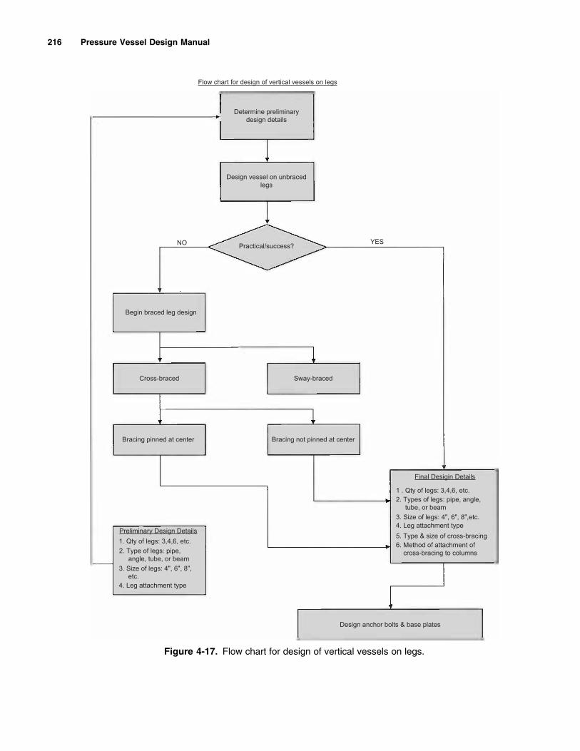
Flow chart for design of vertical vessels on legs
Determine preliminarydesign details
Design vessel on unbracedlegs
Practicalsuccess YESNO
Begin braced leg design
Cross-braced Sway-braced
Bracing not pinned at centerBracing pinned at center
1 Qty of legs 346 etc2 Type of legs pipe angle tube or beam
4 Leg attachment type
Design anchor bolts amp base plates
3 Size of legs 4 6 8 etc
5 Type amp size of cross-bracing6 Method of attachment of cross-bracing to columns
3 Size of legs 4 6 8etc4 Leg attachment type
Preliminary Design Details
Final Desigin Details
1 Qty of legs 346 etc
Figure 4-17 Flow chart for design of vertical vessels on legs
216 Pressure Vessel Design Manual
Procedure 4-5 Seismic Design ndash Vessel on Braced Legs
Notation
Ab frac14 Area brace in2
Ac frac14 Area column in2
Abr frac14 Area brace required in2
Ca frac14 Corrosion allowance inDc frac14 Centerline diameter of columns inE frac14 Modulus of elasticity psif frac14 Maximum force in brace Lbsfa frac14 Axial stress compression psift frac14 Tension stress psiFa frac14 Allowable axial stress psiFb frac14 Allowable stress bending psiFc frac14 Allowable stress compression psiFD frac14 Axial load on column due to dead weight lbsFh frac14 Horizontal seismic force LbsFL frac14 Axial load on column due to seismic or wind lbsFt frac14 Allowable stress tension psiFV frac14 Vertical seismic force LbsFy frac14 Yield strength of material at temperature psig frac14 Acceleration due to gravity 386 insec2
Ib frac14 Moment of inertia bracing in4
Ir frac14 Required moment of inertia in4
Ic frac14 Moment of inertia column in4
k frac14 End connection coefficient columnsMo frac14 Overturning moment in-LbsN frac14 Number of columnsn frac14 Number of active rods per panel use 1 for sway
bracing 2 for cross bracingn0 frac14 Factor for cross bracing use 1 for unpinned and 2
for pinned at centerQ frac14 Maximum axial force in column Lbsrb frac14 Radius of gyration brace inrc frac14 Radius of gyration column inSr frac14 Slenderness ratioT frac14 Period of vibration secondsV frac14 Base shear LbsVn frac14 Horizontal force per column LbsWo frac14 Weight operating Lbsw frac14 Unit weight of liquid pcf
DL frac14 Change in length of brace ind frac14 Lateral deflection of vessel in
Horizontal Load Distribution Vn
The horizontal load on any one leg is dependent on thedirection of the leg bracing The horizontal force V istransmitted to the legs through the bracing Thus thegeneral equation
Vn frac14 Vsin2 an1 thorn sin2an
N
and SVn frac14 V
Vertical Load Distribution Fn
The vertical load distribution on braced and unbracedlegs is identical The force on any one leg is equal to thedead load plus the greater of seismic or wind and the angleof that leg to the direction of force V The general equa-tion for each case is as follows
For Case 1 For Case 2
FD frac14 Fv
NFD frac14 Fv
N
FL frac14 4M
NdFL frac14 4Md1
Nd2
Fn frac14 FD FL cos fn Fn frac14 FD FL cos fn
Design of Columns
bull Base ShearVUse worst case of wind or seismicV frac14 ________
bull Overturning Moment Mo
Mo frac14 L Vbull Maximum Dead load FD
FD frac14 ethTHORNWo=Nbull Maximum EarthquakeWind Load FEW
FL frac14 thorn= 4 Mo=N Dc
bull Maximum Column Load QSelect worst case from Table or use
Q frac14 FD thorn = FL
Q max compression frac14 QC frac14
Q max tension frac14 QT frac14
Table 4-12Dimensions for d1
No of Legs d1
3 750 DC
4 707 DC
6 866 DC
8 924 DC
10 951 DC
12 966 DC
16 981 DC
Design of Vessel Supports 217
Note If there is no uplift then there is no tension force
bull Leg selection
Use frac14 __________
AC frac14 ___________
Compression Casebull Compressive stress fa
fa frac14 QC=AC Fa
bull Slenderness ratio Sr frac14 khrcFafrac14
Tension Casebull Tension stress ft
ft frac14 QT=AC Ft
bull Allowable tension stress Ft
FT frac14 1206
Fy
Cross Bracing
Note Loads in cross bracing are tension andcompression
Compression Casebull Case 1 Pinned at center
Ir frac14 FL12=4p2E
Case 2 Not pinned at center
Ir frac14 FL12=p2E
Figure 4-18 Load diagrams for horizontal load distribution
D
FV
Fh
Fn Fn
FV
cg
ff
L
H
Y
V
Four legs (for illustration only)
218 Pressure Vessel Design Manual
Design of Vessel Supports 219
METHOD 1 METHOD 2 METHOD 3
Vn = Horiz shear per lug
Worst case from Table dependent on number of legs and direction of seismic force (between legs or through legs)
NA Vn =VN
f = Max force in brace
f = Vn n Sin θ f = 2 Wo 2 N Sin θ f = Vn Sin θ
ΔL = Change in length of brace
ΔL = (f L1 ) (E Ab) ΔL = (f L1 ) (E Ab) ΔL = (2 Wo L1 ) (2 N E Ab Sin θ)
δ = Lateral deflection of Vessel
δ = ΔL Sin θ δ = ΔL Sin θ δ = ΔL Sin θ
T = Period of vibration
T = 2 π ( δ g )12 T = 2 π ( δ g )12 T = 2 π ( δ g )12
VESSEL ON BRACED LEGS - SEISMIC DESIGN
NOTES
1 Approx POV per ASCE 7-05 Ta = Ct hnx
220 Pressure Vessel Design Manual
Figure 4-19 Load diagrams for vertical load distribution
Table 4-13Summary of loads forces amp moments at support locations
Qty of
Columns Leg No
Case 1 At Columns Case 2 Between Columns
Horiz ( Vn ) Vertical ( Q ) Horiz ( Vn ) Vertical ( Q )
6 1 thorn 0083 V FD thorn 1000 FL thorn 0125 V FD thorn 0866 FL
2 thorn 0208 V FD thorn 0500 FL thorn 0250 V FD
3 thorn 0208 V FD 0500 FL thorn 0125 V FD 0866 FL
4 thorn 0083 V FD 1000 FL thorn 0125 V FD 0866 FL
5 thorn 0208 V FD 0500 FL thorn 0250 V FD
6 thorn 0208 V FD thorn 0500 FL thorn 0125 V FD thorn 0866 FL
8 1 thorn 0036 V FD thorn 1000 FL thorn 0062 V FD thorn 0923 FL
2 thorn 0125 V FD thorn 0707 FL thorn 0187 V FD thorn 0382 FL
3 thorn 0213 V FD thorn 0187 V FD 0382 FL
4 thorn 0125 V FD 0707 FL thorn 0062 V FD 0923 FL
5 thorn 0036 V FD 1000 FL thorn 0062 V FD 0923 FL
6 thorn 0125 V FD 0707 FL thorn 0187 V FD 0382 FL
7 thorn 0213 V FD thorn 0187 V FD thorn 0382 FL
8 thorn 0125 V FD thorn 0707 FL thorn 0062 V FD thorn 0923 FL
10 1 thorn 0019 V FD thorn 1000 FL thorn 0034 V FD thorn 0951 FL
2 thorn 0075 V FD thorn 0809 FL thorn 0125 V FD thorn 0587 FL
3 thorn 0165 V FD thorn 0309 FL thorn 0180 V FD
4 thorn 0165 V FD 0309 FL thorn 0125 V FD 0587 FL
5 thorn 0075 V FD 0809 FL thorn 0034 V FD 0951 FL
6 thorn 0019 V FD 1000 FL thorn 0034 V FD 0951 FL
7 thorn 0075 V FD 0809 FL thorn 0125 V FD 0587 FL
8 thorn 0165 V FD 0309 FL thorn 0180 V FD
9 thorn 0165 V FD thorn 0309 FL thorn 0125 V FD thorn 0587 FL
10 thorn 0075 V FD thorn 0809 FL thorn 0034 V FD thorn 0951 FL
12 1 thorn 0011 V FD thorn 1000 FL thorn 0020 V FD thorn 0965 FL
2 thorn 0047 V FD thorn 0866 FL thorn 0083 V FD thorn 0707 FL
3 thorn 0119 V FD thorn 0500 FL thorn 0145 V FD thorn 0258 FL
4 thorn 0155 V FD thorn 0145 V FD 0258 FL
5 thorn 0119 V FD 0500 FL thorn 0083 V FD 0707 FL
6 thorn 0047 V FD 0866 FL thorn 0020 V FD 0965 FL
7 thorn 0011 V FD 1000 FL thorn 0020 V FD 0965 FL
8 thorn 0047 V FD 0866 FL thorn 0083 V FD 0707 FL
(Continued )
Design of Vessel Supports 221
Use ___________
Ibfrac14 ___________
rbfrac14 ___________
Abfrac14 ___________
bull Compressive Stress fa
fa frac14 Qc=Ac Fabull Slenderness ratio Srfrac14KL1n0rb n0 frac14 1 for not pinned2 for pinnedFafrac14
Tension Casebull Tension stress ft
ft frac14 f=Ab Ftbull Allowable tension stress Ft
FT frac14 1206
Fy
Sway Bracing
Note Loads in sway bracing are tension only
bull Area of bracing required Abr
Abr frac14 f=Ft
bull Allowable tensile stress Ft
FT frac14 1206
Fy
End Connections
bull Shear per bolt frac14 5 f number of boltsbull Shear per inch of weldfrac14 5 f inch of weld
Table 4-13Summary of loads forces amp moments at support locationsdcontrsquod
Qty of
Columns Leg No
Case 1 At Columns Case 2 Between Columns
Horiz ( Vn ) Vertical ( Q ) Horiz ( Vn ) Vertical ( Q )
9 thorn 0119 V FD 0500 FL thorn 0145 V FD 0258 FL
10 thorn 0155 V FD thorn 0145 V FD thorn 0258 FL
11 thorn 0119 V FD thorn 0500 FL thorn 0083 V FD thorn 0707 FL
12 thorn 0047 V FD thorn 0866 FL thorn 0020 V FD thorn 0965 FL
16 1 thorn 0004 V FD thorn 1000 FL thorn 0009 V FD thorn 0980 FL
2 thorn 0021 V FD thorn 0923 FL thorn 0040 V FD thorn 0831 FL
3 thorn 0062 V FD thorn 0707 FL thorn 0084 V FD thorn 0555 FL
4 thorn 0103 V FD thorn 0382 FL thorn 0115 V FD thorn 0195 FL
5 thorn 0120 V FD thorn 0115 V FD 0195 FL
6 thorn 0103 V FD 0382 FL thorn 0084 V FD 0555 FL
7 thorn 0062 V FD 0707 FL thorn 0040 V FD 0831 FL
8 thorn 0021 V FD 0923 FL thorn 0009 V FD 0980 FL
9 thorn 0004 V FD 1000 FL thorn 0009 V FD 0980 FL
10 thorn 0021 V FD 0923 FL thorn 0040 V FD 0831 FL
11 thorn 0062 V FD 0707 FL thorn 0084 V FD 0555 FL
12 thorn 0103 V FD 0382 FL thorn 0115 V FD 0195 FL
13 thorn 0120 V FD thorn 0115 V FD thorn 0195 FL
14 thorn 0103 V FD thorn 0382 FL thorn 0084 V FD thorn 0555 FL
15 thorn 0062 V FD thorn 0707 FL thorn 0040 V FD thorn 0831 FL
16 thorn 0021 V FD thorn 0923 FL thorn 0009 V FD thorn 0980 FL
Notes
1 Radius Rn in equations will be R1 if a girder is used Rc if no girder is used
Table 4-14Allowable shear load in kips (bolts and welds per AISC steel
construction manual ASD method)
Bolt Size A-307 A-325
625rdquo 368 736
75rdquo 530 106
875rdquo 721 144
1rdquo 942 188
1125rdquo 119 238
WELD SIZE E60XX E70XX
1875 239 278
25 318 371
3125 398 464
375 477 557
4375 556 650
222 Pressure Vessel Design Manual
Post Connection Plate
See ldquoDesign of Ring Girdersrdquo
Notes
1 Cross-bracing the legs will conveniently reducebending in legs due to overturning moments (ldquowindand earthquakerdquo) normally associated with unbracedlegs The lateral bracing of the legs must be sized totake lateral loads induced in the frame that wouldotherwise cause the legs to bend
2 Legs may be made from angles pipes channelsbeam sections or rectangular tubing
3 Legs longer than about 7 ft should be cross-braced4 Check to see if the cross-bracing interferes with
piping from bottom head5 Shell stresses at the leg attachment should be
investigated for local loads For thin shells extendldquoYrdquo Legs should be avoided as a support methodfor vessels with high shock loads or vibrationservice
Procedure 4-6 Seismic Design ndash Vessel on Rings [458]
Notation
Cv Ch frac14 verticalhorizontal seismic factorsAb frac14 bearing area in2
Fv Fh frac14 verticalhorizontal seismic force lbN frac14 number of support pointsn frac14 number of gussets at supports
P Pe frac14 internalexternal pressure psiW frac14 vessel weight under consideration lbsb frac14 bending stress psi
sf frac14 circumferential stress psiKr frac14 internal moment coefficientCr frac14 internal tensioncompression coefficientZ frac14 required section modulus ring in3
I1ndash2 frac14 moment of inertia of rings in4
S frac14 code allowable stress tension psiA1ndash2 frac14 cross-sectional area ring in2
TC TT frac14 compressiontension loads in rings lbM frac14 internal moment in rings in-lb
Table 4-15Suggested sizes of legs and cross-bracing
Vessel OD (in)
Tan to Tan
Length (in)
Support Leg
Angle Sizes (in)
Base Plate
Size (in)
Bracing Angle
Size (in)
Bolt
Size (in) Y (in)
Up to 30 Up to 240 (3) 3 3 frac14 6 6 ⅜ 2 2 frac14 frac34 12
Up to 120 (4) 3 3 frac14 6 6 ⅜ frac34 8
30 to 42 121 to 169 (4) 3 3 frac14 6 6 ⅜ 2 2 frac14 frac34 10
170 to 240 (4) 3 3 ⅜ 6 6 frac12 frac34 12
Up to 120 (4) 3 3 ⅜ 6 6 frac12 2frac12 2frac12 frac14 frac34 8
43 to 54 121 to 169 (4) 3 3 ⅜ 6 6 frac12 frac34 10
170 to 240 (4) 4 4 ⅜ 8 8 ⅜ frac34 12
Up to 120 (4) 4 4 ⅜ 8 8 ⅜ 2frac12 2frac12 frac14 1 8
55 to 56 121 to 169 (4) 4 4 frac12 8 8 frac12 1 10
170 to 240 (4) 4 4 frac12 8 8 frac12 1 12
Up to 120 (4) 5 5 ⅜ 9 9 frac12 3 3 frac14 1⅛ 8
67 to 78 121 to 169 (4) 5 5 ⅜ 9 9 frac12 1⅛ 10
170 to 240 (4) 6 6 frac12 10 10 frac12 1⅛ 12
Up to 120 (4) 6 6 frac12 10 10 frac12 3 3 frac14 1⅛ 10
79 to 80 121 to 169 (4) 6 6 frac12 10 10 frac12 1⅛ 12
170 to 240 (4) 6 6 frac12 10 10 frac12 1⅜ 12
Up to 120 (4) 6 6 frac12 10 10 frac12 3 3 ⅜ 1⅜ 12
91 to 102 121 to 169 (6) 6 6 frac12 10 10 frac12 1⅜ 12
170 to 240 (6) 6 6 ⅝ 10 10 frac34 1⅜ 12
Design of Vessel Supports 223
Mb frac14 bending moment in base ring in-lb greaterof Mx or My
Bp frac14 bearing pressure psiQ frac14 maximum vertical load at supports lbf frac14 radial loads on rings lb
bull Internal moment in rings M1 and M2Upper ring
M1 frac14 krfR1 cos q
Lower ring
M2 frac14 krfR2 cos q
Note cos q is to be used for nonradial loads Disregard ifload f is radial
bull Required section modulus of upper ring Z
Z frac14 M1
S
Note It is assumed the lower ring is always larger or of
equal size to the upper ring
bull Tensioncompression loads in rings Note In generalthe upper ring is in compression at the application ofthe loads and in tension between the loads The lowerring is in tension at the loads and in compressionbetween the loads Since the governing stress isnormally at the loads the governing stresses wouldbe
Upper ring
Tc frac14 Crf cos q
Figure 4-20 Typical dimensional data and forces for a vessel supported on rings
224 Pressure Vessel Design Manual
L3A
A A
A
L3
L4
L4
F2
F2
Mmax = GREATER OF
Vmax = Greater of F1 or F2
MAA = F1 L3
Or F2 L4
LOWER PORTIONGOVERNS
UPPER PORTIONGOVERNS
F1
F1
LOS
LOS
INFLUENCE OF RING SUPPORT POSITIONING
Figure 4-21 Vessel supported on rings (Influence of support positioning)
Design of Vessel Supports 225
Figure 4-22 Coefficients for rings
226 Pressure Vessel Design Manual
Lower ring
TT frac14 Crf cos q
where Cr is the maximum positive value for TT and themaximum negative value for Tcbull Maximum circumferential stress in shell sfCompression in upper ring
sf frac14 ethTHORN PeRm
t Tc
A1
Tension in lower ring
sf frac14 PRm
tthorn TT
A2
bull Maximum bending stress in shell
Upper ring
sb frac14 M1C1
I1Lower ring
sb frac14 M2C2
I2bull Maximum bending stress in ringUpper ring
sb frac14 M1y1I1
Figure 4-23 Coefficients for rings (Signs in the table arefor loads as shown Reverse signs for loads are in theopposite direction)
Figure 4-24 Coefficients for rings (Signs in the table arefor loads as shown Reverse signs for loads are in theopposite direction)
Design of Vessel Supports 227
Figure 4-25 Properties of upper ring
Figure 4-26 Properties of lower ring
Figure 4-27 Determining the thickness of the lower ringto resist bending
Table 4-16Maximum bending moments in a bearing plate with gussets
lsquo
bMx
x[ 05by[ lsquo
Mx
x[ 05by[0
0 0 ()0500 Bpl2
0333 00078 Bp b2 ()0428 Bpl
2
05 00293 Bp b2 ()0319 Bpl
2
0666 00558 Bp b2 ()0227 Bpl
2
10 00972 Bp b2 ()0119 BPl
2
15 01230 Bp b2 ()0124 Bpl
2
20 01310 Bp b2 ()0125 BPl
2
30N 01330 Bp b2 ()0125 BPl
2
Reprinted by permission of John Wiley amp Sons Inc
From Process Equipment Design Table 103 (See Note 2)
228 Pressure Vessel Design Manual
bull Properties of upper ringbull Properties of lower ring
Lower ring
sb frac14 M2y2I2
bull Thickness of lower ring to resist bendingBearing area AbAb frac14
Bearing pressure Bp
Bp frac14 QAb
From Table 4-16 select the equation for the maximumbending moment in the bearing plate Use the greater ofMx or My
lsquo
bfrac14
Mb frac14Minimum thickness of lower ring tb
tb frac14ffiffiffiffiffiffiffiffiffi6Mb
S
r
Notes
1 Rings may induce high localized stresses in shellimmediately adjacent to rings
2 When lb 15 the maximum bending momentoccurs at the junction of the ring and shell Whenlbgt 15 the maximum bending moment occurs atthe middle of the free edge
3 Since the mean radius of the rings may be unknownat the beginning of computations yet is required fordetermining maximum bending moment substituteRm as a satisfactory approximation at that stage
4 The following values may be estimatedbull Ring thickness The thickness of each ring isarbitrary and can be selected by the designer Asuggested value is
tb frac14 03
ffiffiffiffiffiffiffiffiffiffiffiMmax
S3
r
bull Ring spacing Ring spacing is arbitrary and can beselected by the designer A suggested minimumvalue is
h frac14 B D
bull Ring depth The depth of ring cannot be computeddirectly but must be computed by successiveapproximations As a first trial
d frac14 21
ffiffiffiffiffiffiffiffiffiffiffiMmax
trS
r
Procedure 4-7 Seismic Design ndash Vessel on Lugs [58ndash13]
Notation
Rm frac14 center line radius of shell inN frac14 number of equally spaced lugsW frac14 weight of vessel plus contents lbf frac14 radial load lb
Fh frac14 horizontal seismic force lbFv frac14 vertical seismic force lbVh frac14 horizontal shear per lug lbVv frac14 vertical shear per lug lbQ frac14 vertical load on lugs lb
g b frac14 coefficientsMc frac14 external circumferential moment inndashlbML frac14 external longitudinal moment in-lb
Mf frac14 internal bending moment circumferentialin-lbin
Mx frac14 internal bending moment longitudinal in -lbin
Nf frac14 membrane force in shell circumferential lbin
Nx frac14 membrane force in shell longitudinal lbinP frac14 internal pressure psiCh frac14 horizontal seismic factorCv frac14 vertical seismic factor
CcCi frac14 multiplication factors for Nf and Nx forrectangular attachments
KCK1 frac14 coefficients for determining b for momentloads on rectangular areas
Design of Vessel Supports 229
K1K2 frac14 coefficients for determining b for radial loadson rectangular areas
KnKb frac14 stress concentration factors (see Note 5)sf frac14 circumferential stress psisx frac14 longitudinal stress psits frac14 thickness of shell intp frac14 thickness of reinforcing pad ina frac14 coefficient of thermal expansion inindegFz frac14 radial deflection in
Neutralaxis
ML
Rm
bVh
a
Q1 Inner Outer
aQ3
Neutralaxis
bVh
ML = Q3a ndash VhbM1 = Q1a + Vhb
C
Figure 4-28 Dimensions and forces for support lug
OuterIug
Q1Q3
Fv
Fh
Fv
cg L
B
Innerlug
Neutralaxis
Figure 4-29 Case 1 Lugs below the center of gravity
InnerIug
Outerlug
Neutralaxis
B
LQ1
Q3
FvFh
Fv
cg
Figure 4-30 Case 2 Lugs above the center of gravity
00
90deg90deg
180deg
270deg270deg
b
2C12C1
2C2
2C2
b
Figure 4-31 Area of loading
L3
L3
L4
L4
F2
F2
F1
F1
LOSAA
A ALOS
Mmax = GREATER OF
Vmax = Greater of F1 or F2
MAA = F1 L3
Or F2 L4
LOWER PORTION
GOVERNS
UPPER PORTION
GOVERNS
Figure 4-32 Vessel supported on lugs (Influence ofsupport positioning)
230 Pressure Vessel Design Manual
Design of Vessel Supports 231
Table 4-18Coefficients for longitudinal moment ML
b1b2 g CL for Nf CL for Nx KL for Mf KL for Mx
15 075 043 180 124
50 077 033 165 116
025 100 080 024 159 111
200 085 010 158 111
300 090 007 156 111
15 090 076 108 104
50 093 073 107 103
05 100 097 068 106 102
200 099 064 105 102
300 110 060 105 102
15 089 100 101 108
50 089 096 100 107
1 100 089 092 098 105
200 089 099 095 101
300 095 105 092 096
15 087 130 094 112
50 084 123 092 110
2 100 081 115 089 107
200 080 133 084 099
300 080 150 079 091
15 068 120 090 124
50 061 113 086 119
4 100 051 103 081 112
200 050 118 073 098
300 050 133 064 083
Reprinted by permission of the Welding Research Council
Table 4-17Coefficients for circumferential moment Mc
b1b2 g Cc for Nf Cc for Nx Kc for Mf Kc for Mx
15 031 049 131 184
50 021 046 124 162
025 100 015 044 116 145
200 012 045 109 131
300 009 046 102 117
15 064 075 109 136
50 057 075 108 131
05 100 051 076 104 116
200 045 076 102 120
300 039 077 099 113
15 117 108 115 117
50 109 103 112 114
1 100 097 094 107 110
200 091 091 104 106
300 085 089 099 102
15 170 130 120 097
50 159 123 116 096
2 100 143 112 110 095
200 137 106 105 093
300 130 100 100 090
15 175 131 147 108
50 164 111 143 107
4 100 149 081 138 106
200 142 078 133 102
300 136 074 127 098
Reprinted by permission of the Welding Research Council
232 Pressure Vessel Design Manual
Analysis when Reinforcing Pads are Used
Step 1 Compute radial loads f
Step 3 Compute equivalent b values
Step 2 Compute geometric parameters
Figure 4-33 Dimensions of load areas for radial loads
Case 1 Case 2 Case 3
Outer f1 frac14 3ML1
4C2f1 frac14 3ML1
4C2
Sides f2 frac14 3ML2
4C2f2 frac14 3ML2
4C2
Inner f3 frac14 3ML3
4C2f3 frac14 3ML3
4C2
Table 4-19
Four values of b are computed for use in
determining Nf Nx Mf and Mx as follows The values of K1 and K2 are taken from Table 4-19 Values of coefficient K1 and K2
b1b2 Dagger 1 b K1 K2
b frac14 frac121 1
3ethb1b2
1THORNeth1 k1THORNffiffiffiffiffiffiffiffiffiffib1b2
pba for Nf frac14 Nf 091 148
bb for Nxfrac14 Nx 168 12
b1b2 lt 1
b frac14 frac121 4
3eth1 b1
b2THORNeth1 k2THORN
ffiffiffiffiffiffiffiffiffiffiffiffiffib1=b2
pbc for Mf frac14 Mf 176 088
bd for Mx frac14 Mx 12 125
Reprinted by permission of the Welding Research Council
At Edge of Attachment At Edge of Pad
Rm frac14 IDthorn ts thorn tp2
Rm frac14 IDthorn ts2
t frac14ffiffiffiffiffiffiffiffiffiffiffiffiffit2s thorn t2p
qt frac14 ts
g frac14 Rm=t g frac14 Rm=t
b1 frac14 C1=Rm b1 frac14 d1=Rm
b2 frac14 4C2=3Rm b2 frac14 d2=Rm
b1=b2 b1=b2
Design of Vessel Supports 233
Step 4 Compute stresses for a radial load
Radial Load Figure b Values from Figure Forces and Moments Stress
Membrane 7-21A ba frac14 NfRm
ffrac14 eth THORN Nf frac14 eth THORNf
Rmfrac14 sf frac14 KnNf
tfrac14
7-21B bb frac14 NxRm
ffrac14 eth THORN Nx frac14 eth THORNf
Rmfrac14 sx frac14 KnNx
tfrac14
Bending 7-22A bc frac14 Mf
ffrac14 eth THORN Mf frac14 eth THORNf frac14 sf frac14 6KbMf
t2frac14
7-22B bd frac14 Mx
ffrac14 eth THORN Mx frac14 eth THORNf frac14 sx frac14 6KbMx
t2frac14
234 Pressure Vessel Design Manual
Figure 4-34 Radial loads F and f
Design of Vessel Supports 235
7
7
B
Fh
Case 1 Load through lugs
Case 2 Load between lugs
Fh
V7
V7
V8
V8
Φ1 = 0
Φ2 = 45ordm
Φ3 = 90ordm
Φ4 = 135ordm
Φ5 = 180ordm
Φ1 = 225ordm
Φ2 = 675ordm
Φ3 = 1125ordm
Φ4 = 1575ordm
V1
V1
V2
V2
B1
V3
V3
V4
V4
V5
V5
V6
V6
8
8
6
6
5
5
4
4
3
3
2
2
1
1
Φ2
Φ2
Φ1
Φ3
Φ3
Φ4
Φ4
Φ5
Figure 4-35 Vessel supported on (8) lugs
236 Pressure Vessel Design Manual
Design of Vessel Supported on (8) Lugs
Item Formula Calculation
Lateral Force Fh frac14 Ch W
Horizontal ShearLug Vh frac14 Fh N
Vertical Force FV frac14 ( 1 thorn CV ) W
Overturning Moment M frac14 Fh L
Dead LoadLug VV frac14 FV N
Worst Case Vertical Live Load per Lug FL frac14 4 M N B
VERTICAL LIVE LOAD ON EACH LUG FLn
LUG CASE 1 CASE 2
1 FL 924 FL
2 707 FL 383 FL
3 0 thorn 383 FL
4 thorn707 FL thorn 924 FL
5 thorn FL thorn 924 FL
6 707 FL thorn 383 FL
7 0 383 FL
8 thorn 707 FL 924 FL
Formulas in Table are based on the following equations
CASE 1 FL frac14 4 M cosfn N B
CASE 2 FL frac14 4 M cosfn N B1
Vertical Load on any Lug Qn frac14 VV thorn FLn
Worst Case Load per Lug Q frac14 VV thorn FL
Longitudinal Moment for any Given Lug MLn frac14 Qn a thorn- Vh b
Longitudinal Moment for any Worst Case ML frac14 Q a thorn- Vh b
Design of Vessel Supported on (8) Lugs (Example) Data
ITEM FORMULA CALCULATION Ch frac14 1
Lateral Force Fh frac14 Ch W Fh frac14 1 (141K ) frac14 141K CV frac14 2
Horizontal ShearLug Vh frac14 Fh N Vh frac14 141K 8 frac14 176K W frac14 141K
Vertical Force FV frac14 ( 1 thorn CV ) W FV frac14 (1 thorn 2 ) 141K frac14 1692K L frac14 84
Overturning Moment M frac14 Fh L M frac14 141K (84) frac14 1184 In-Kips a frac14 12
Dead LoadLug VV frac14 FV N VV frac14 1692K 8 frac14 2115K b frac14 624
Worst Case Vertical Live Load per Lug FL frac14 4 M N B FL frac14 4(1184K ) (8) 16025 frac14 369K B frac14 16025
B1 frac14 11331
VERTICAL LIVE LOAD ON EACH LUG FLn
LUG CASE 1 CASE 2
1 FL 924 FL
2 707 FL 383 FL
3 0 thorn 383 FL
4 thorn707 FL thorn 924 FL
5 thorn FL thorn 924 FL
6 707 FL thorn 383 FL
7 0 383 FL
8 thorn 707 FL 924 FL
Formulas in Table are based on the following equations
CASE 1 FL frac14 4 M cosfn N B
CASE 2 FL frac14 4 M cosfn N B1
Vertical Load on any Lug Qn frac14 VV thorn FLn
Worst Case Load per Lug Q frac14 VV thorn FL Q frac14 2115 thorn 369 frac14 2484K
Longitudinal Moment for any Given Lug MLn frac14 Qn a thorn- Vh b
Longitudinal Moment for any Worst Case ML frac14 Q a thorn- Vh b ML frac14 2484K (12) thorn 176K (624) frac14 309 in-Kips
Design of Vessel Supports 237
Check lug for radial thermal expansion zr
DT frac14 Design temperature oFR frac14 Radius frac14 B 2a frac14 Coefficient of thermal expansion inin oF
DT frac14 Change in temperature from 70 oF
zr frac14 a DT R frac14
Example
R frac14 80125 in
DT frac14 925Fa frac14 79
106 in=in=F
DT frac14 925 70 frac14 855Fzr frac14 79
106 855 80125 frac14 541 in
Use slotted holes
Size of anchor bolts Required Ar
Due to Overturning Moment
Ar frac14 frac12eth4 M=BTHORN Wfrac121=ethNb SbTHORN
Nb frac14 Number of anchor boltsIf Ar is negative there is no uplift
Due to Shear
Shear lug fSfS frac14 Fh=Nb
Ar frac14 fS=FS
Use minimum size of anchor bolts of 075 in diameter
Notes
1 A change in location of the cg for various oper-ating levels can greatly affect the moment at lugsby increasing or decreasing the ldquoLrdquo dimensionDifferent levels and weights should be investigatedfor determining worst case (ie full half-fullempty etc)
2 This procedure ignores effects of sliding frictionbetween lugs and beams during heatingcoolingcycles These effects will be negligible forsmall-diameter vessels relatively low operating
temperatures or where slide plates are used toreduce friction forces Other cases should beinvestigated
3 Since vessels supported on lugs are commonlylocated in structures the earthquake effects will bedependent on the structure as well as on the vesselThus horizontal and vertical seismic factors mustbe provided
4 If reinforcing pads are used to reduce stresses in theshell or a design that uses them is being checkedthen Bijlaard recommends an analysis that convertsmoment loadings into equivalent radial loads Theattachment area is reduced about two-thirdsStresses at the edge of load area and stresses at theedge of the pad must be checked See ldquoAnalysisWhen Reinforcing Pads are Usedrdquo
5 Stress concentration factors are found in theprocedure on local stresses
6 To determine the area of attachment see ldquoAttach-ment Parametersrdquo Please note that if a top(compression) plate is not used then an equivalentrectangle that is equal to the moment of inertia ofthe attachment and whose width-to-height ratio isthe same must be determined The neutral axis isthe rotating axis of the lug passing through thecentroid
7 Stiffening effects due to proximity to major stiff-ening elements though desirable have beenneglected in this procedure
8 Assume effects of radial loads as additive to thosedue to internal pressure even though the loadingsmay be in the opposite directions Althoughconservative they will account for the highdiscontinuity stresses immediately adjacent to thelugs
9 In general the smaller the diameter of the vesselthe further the distribution of stresses in thecircumferential direction In small diametervessels the longitudinal stresses are confined toa narrow band The opposite becomes true forlarger-diameter vessels or larger Rmt ratios
10 If shell stresses are excessive the followingmethods may be utilized to reduce the stressesa Add more lugsb Add more gussetsc Increase angle q between gussetsd Increase height of lugs he Add reinforcing pads under lugs
238 Pressure Vessel Design Manual
f Increase thickness of shell course to which lugsare attached
g Add top and bottom plates to lugs or increasewidth of plates
h Add circumferential ring stiffeners at top andbottom of lugs
Procedure 4-8 Seismic Design ndash Vessel on Skirt [123]
Notation
T frac14 period of vibration secSI frac14 code allowable stress tension psiH frac14 overall height of vessel from bottom of base
plate fthx frac14 height from base to center of section or eg
of a concentrated load fthi frac14 height from base to plane under consider-
ation fta b g frac14 coefficients from Table 4-20 for given plane
based on hxHWx frac14 total weight of section kipsW frac14 weight of concentrated load or mass kipsWo frac14 total weight of vessel operating kipsWh frac14 total weight of vessel above the plane under
consideration kipswx frac14 uniformly distributed load for each section
kipsftFx frac14 lateral force applied at each section kipsV frac14 base shear kipsVx frac14 shear at plane x kipsMx frac14 moment at plane x ft-kipsMb frac14 overturning moment at base ft-kipsD frac14 mean shell diameter of each section ft or inE frac14 modulus of elasticity at design temperature
106 psiEl frac14 joint efficiencyt frac14 thickness of vessel section inPi frac14 internal design pressure psiPe frac14 external design pressure psi
Da Dg frac14 difference in values of a and g from top tobottom of any given section
lx frac14 length of section ftsxt frac14 longitudinal stress tension psisxc frac14 longitudinal stress compression psiRo frac14 outside radius of vessel at plane under
consideration inA frac14 code factor for determining allowable
compressive stress B
B frac14 code allowable compressive stress psiF frac14 lateral seismic force for uniform vessel kipsCh frac14 horizontal seismic factor
Cases
Case 1 Uniform Vessels For vessels of uniform crosssection without concentrated loads (ie reboilerspacking large liquid sections etc) weight can beassumed to be uniformly distributed over the entireheight
Wo frac14H frac14D frac14t frac14
T frac14 00000265
HD
2ffiffiffiffiffiffiffiffiffiffiWoDHt
r
Note POV may be determined from chart in Figure4-6 H and D are in feet t is in inches
V frac14 ChWo
F frac14 V
Mb frac14 2=3ethFHTHORN
Moment at any height hj
Ma frac14 F
2H3
hi
Case 2 Nonuniform VesselsProcedure for finding period of vibration moments
and forces at various planes for nonuniform vesselsA nonuniform vertical vessel is one that varies in
diameter thickness or weight at different elevations Thisprocedure distributes the seismic forces and thus baseshear along the column in proportion to the weights of
Design of Vessel Supports 239
each section The results are a more accurate and realisticdistribution of forces and accordingly a more accurateperiod of vibration The procedure consists of two mainsteps
Step 1 Determination of period of vibration (POV) TDivide the column into sections of uniform weight anddiameter not to exceed 20 of the overall height Auniform weight is calculated for each section Diameterand thicknesses are taken into account through factorsa and g Concentrated loads are handled as separatesections and not combined with other sections Factor
b will proportion effects of concentrated loads Thecalculation form is completed for each section from leftto right then totaled to the bottom These totals are usedto determine T (POV) and the POV in turn is usedto determine V and Ft
Step 2 Determination of forces shears and momentsAgain the vessel is divided into major sections as inStep 1 however longer sections should be furthersubdivided into even increments For these calcula-tions sections should not exceed 10 of heightRemember the moments and weights at each planewill be used in determining what thicknesses arerequired It is convenient to work in 8 to 10 footincrements to match shell courses Piping traysplatforms insulation fireproofing and liquid weightsshould be added into the weights of each section wherethey occur Overall weights of sections are used indetermining forces not uniform weights Momentsdue to eccentric loads are added to the overall momentof the column
Notes for nonuniform vessels
1 Combine moments with corresponding weights ateach section and use allowable stresses to deter-mine required shell and skirt thicknesses at theelevation
2P
uDa and WbH are separate totals and arecombined in computation of POV
3 (D10)3 is used in this expression if kips are usedUse (D)3 if lb are used
4 For vessels having a lower section several times thediameter of the upper portion and where the lowerportion is short compared to the overall height thePOV can more accurately be determined bvfinding the POV of the upper section alone (seeFigure 438a)
5 For vessels where Rt is large in comparison tothe supporting skirt the POV calculated bythis method may be overly conservative Moreaccurate methods may be employed (seeFigure 438b)
6 Make sure to add moment due to any eccentric loadsto total moment
Figure 4-36 Typical dimensional data forces andloadings on a uniform vessel supported on a skirt (d frac14deflection)
240 Pressure Vessel Design Manual
Figure 4-37 Nonuniform vessel illustrating a) Note 4 andb) Note 5
Figure 4-38 Typical dimensional data forces andloadings on a nonuniform vessel supported on a skirt
Design of Vessel Supports 241
Step 1 PERIOD OF VIBRATION
Partω or W
kft hxH α Δα or βωΔα or WβH γ Δγ
10 2103 10
000Σ =
See Notes 2 and 3
γtΔ310HWβωΔα2
100HT
sumE(D )sum+sum= ⎟
⎠⎞⎜
⎝⎛
E(D10)3tΔγ Note 3
Σ =
242 Pressure Vessel Design Manual
Step 1 PERIOD OF VIBRATION EXAMPLE
INC
LUD
E BO
TTO
M H
EAD
AN
D L
IQU
ID A
S PA
RT
3
H =
112
primendash0Prime
10primendash
0Prime 20primendash
0Prime
40primendash
0Prime16
primendash0Prime
20 T
RAY
S
2primendash
0Prime S
PAC
ING
= 4
2primendash0
Prime
8primendash0Prime 12Prime THK
38PrimeTHK
REB
OIL
ERw
=10
KPS
LIQ
UID
2prime2prime
Design of Vessel Supports 243
Step 2 SHEAR AND MOMENTS
244 Pressure Vessel Design Manual
Step 2 SHEAR AND MOMENTS EXAMPLE
hi (ft) Part Wx (kips) hx (ft)
Wxhx (ft-
kips) Fx (kips)
Vi btm
(kips) Mi (kips)0211211
12 1416 106 1501 732
100 732 4392
11 118 95 1121 54790 1279 14444
10 118 85 1003 48980 1768 29676
9 118 75 885 43270 2199 49511
8 826 65 537 26260 2461 72813
7 59 55 325 15850 2619 98215
6 278 45 1251 61040 3229 127458
5 278 35 973 47430 3704 162125
4 278 25 695 33920 3 10 20 200 098
4140 2008582 278 15 417 203
10 4344 243278
1 875 5 44 02112868256340
= = 194 8951
k = 1 for structures with periods of 05 seconds or lessk = 2 for structures with periods of 25 seconds or morek shall be linearly interpolated with perdiods between 05 and 25 seconds
1iM)ih1i(h1iV)ihx(hxFiM ++minus+++minus=
⎟⎟⎠
⎞⎜⎜⎝
⎛
sum= k
xhxWkxhxW
VxF ⎟⎟⎠
⎞⎜⎜⎝
⎛= kxhxW
8951
4365xF
0 0
12rsquondash
0rdquo10
rsquondash0rdquo
10rsquondash
0rdquo10
rsquondash0rdquo
10rsquondash
0rdquo10
rsquondash0rdquo
10rsquondash
0rdquo10
rsquondash0rdquo
H =
112
rsquondash0rdquo
10rsquondash
0rdquo10
rsquondash0rdquo
10rsquondash
0rdquo
Design of Vessel Supports 245
2 Types of legs pipe angle tube or beam
Flow chart for design of vertical vessels on legs
Determine preliminarydesign details
Design vessel on unbracedlegs
Practicalsuccess YESNO
Begin braced leg design
Cross-braced Sway-braced
Bracing not pinned at centerBracing pinned at center
1 Qty of legs 346 etc2 Type of legs pipe angle tube or beam
4 Leg attachment type
Design anchor bolts amp base plates
3 Size of legs 4 6 8 etc
5 Type amp size of cross-bracing6 Method of attachment of cross-bracing to columns
3 Size of legs 4 6 8etc4 Leg attachment type
Preliminary Design Details
Final Desigin Details
1 Qty of legs 346 etc
Figure 4-17 Flow chart for design of vertical vessels on legs
216 Pressure Vessel Design Manual
Procedure 4-5 Seismic Design ndash Vessel on Braced Legs
Notation
Ab frac14 Area brace in2
Ac frac14 Area column in2
Abr frac14 Area brace required in2
Ca frac14 Corrosion allowance inDc frac14 Centerline diameter of columns inE frac14 Modulus of elasticity psif frac14 Maximum force in brace Lbsfa frac14 Axial stress compression psift frac14 Tension stress psiFa frac14 Allowable axial stress psiFb frac14 Allowable stress bending psiFc frac14 Allowable stress compression psiFD frac14 Axial load on column due to dead weight lbsFh frac14 Horizontal seismic force LbsFL frac14 Axial load on column due to seismic or wind lbsFt frac14 Allowable stress tension psiFV frac14 Vertical seismic force LbsFy frac14 Yield strength of material at temperature psig frac14 Acceleration due to gravity 386 insec2
Ib frac14 Moment of inertia bracing in4
Ir frac14 Required moment of inertia in4
Ic frac14 Moment of inertia column in4
k frac14 End connection coefficient columnsMo frac14 Overturning moment in-LbsN frac14 Number of columnsn frac14 Number of active rods per panel use 1 for sway
bracing 2 for cross bracingn0 frac14 Factor for cross bracing use 1 for unpinned and 2
for pinned at centerQ frac14 Maximum axial force in column Lbsrb frac14 Radius of gyration brace inrc frac14 Radius of gyration column inSr frac14 Slenderness ratioT frac14 Period of vibration secondsV frac14 Base shear LbsVn frac14 Horizontal force per column LbsWo frac14 Weight operating Lbsw frac14 Unit weight of liquid pcf
DL frac14 Change in length of brace ind frac14 Lateral deflection of vessel in
Horizontal Load Distribution Vn
The horizontal load on any one leg is dependent on thedirection of the leg bracing The horizontal force V istransmitted to the legs through the bracing Thus thegeneral equation
Vn frac14 Vsin2 an1 thorn sin2an
N
and SVn frac14 V
Vertical Load Distribution Fn
The vertical load distribution on braced and unbracedlegs is identical The force on any one leg is equal to thedead load plus the greater of seismic or wind and the angleof that leg to the direction of force V The general equa-tion for each case is as follows
For Case 1 For Case 2
FD frac14 Fv
NFD frac14 Fv
N
FL frac14 4M
NdFL frac14 4Md1
Nd2
Fn frac14 FD FL cos fn Fn frac14 FD FL cos fn
Design of Columns
bull Base ShearVUse worst case of wind or seismicV frac14 ________
bull Overturning Moment Mo
Mo frac14 L Vbull Maximum Dead load FD
FD frac14 ethTHORNWo=Nbull Maximum EarthquakeWind Load FEW
FL frac14 thorn= 4 Mo=N Dc
bull Maximum Column Load QSelect worst case from Table or use
Q frac14 FD thorn = FL
Q max compression frac14 QC frac14
Q max tension frac14 QT frac14
Table 4-12Dimensions for d1
No of Legs d1
3 750 DC
4 707 DC
6 866 DC
8 924 DC
10 951 DC
12 966 DC
16 981 DC
Design of Vessel Supports 217
Note If there is no uplift then there is no tension force
bull Leg selection
Use frac14 __________
AC frac14 ___________
Compression Casebull Compressive stress fa
fa frac14 QC=AC Fa
bull Slenderness ratio Sr frac14 khrcFafrac14
Tension Casebull Tension stress ft
ft frac14 QT=AC Ft
bull Allowable tension stress Ft
FT frac14 1206
Fy
Cross Bracing
Note Loads in cross bracing are tension andcompression
Compression Casebull Case 1 Pinned at center
Ir frac14 FL12=4p2E
Case 2 Not pinned at center
Ir frac14 FL12=p2E
Figure 4-18 Load diagrams for horizontal load distribution
D
FV
Fh
Fn Fn
FV
cg
ff
L
H
Y
V
Four legs (for illustration only)
218 Pressure Vessel Design Manual
Design of Vessel Supports 219
METHOD 1 METHOD 2 METHOD 3
Vn = Horiz shear per lug
Worst case from Table dependent on number of legs and direction of seismic force (between legs or through legs)
NA Vn =VN
f = Max force in brace
f = Vn n Sin θ f = 2 Wo 2 N Sin θ f = Vn Sin θ
ΔL = Change in length of brace
ΔL = (f L1 ) (E Ab) ΔL = (f L1 ) (E Ab) ΔL = (2 Wo L1 ) (2 N E Ab Sin θ)
δ = Lateral deflection of Vessel
δ = ΔL Sin θ δ = ΔL Sin θ δ = ΔL Sin θ
T = Period of vibration
T = 2 π ( δ g )12 T = 2 π ( δ g )12 T = 2 π ( δ g )12
VESSEL ON BRACED LEGS - SEISMIC DESIGN
NOTES
1 Approx POV per ASCE 7-05 Ta = Ct hnx
220 Pressure Vessel Design Manual
Figure 4-19 Load diagrams for vertical load distribution
Table 4-13Summary of loads forces amp moments at support locations
Qty of
Columns Leg No
Case 1 At Columns Case 2 Between Columns
Horiz ( Vn ) Vertical ( Q ) Horiz ( Vn ) Vertical ( Q )
6 1 thorn 0083 V FD thorn 1000 FL thorn 0125 V FD thorn 0866 FL
2 thorn 0208 V FD thorn 0500 FL thorn 0250 V FD
3 thorn 0208 V FD 0500 FL thorn 0125 V FD 0866 FL
4 thorn 0083 V FD 1000 FL thorn 0125 V FD 0866 FL
5 thorn 0208 V FD 0500 FL thorn 0250 V FD
6 thorn 0208 V FD thorn 0500 FL thorn 0125 V FD thorn 0866 FL
8 1 thorn 0036 V FD thorn 1000 FL thorn 0062 V FD thorn 0923 FL
2 thorn 0125 V FD thorn 0707 FL thorn 0187 V FD thorn 0382 FL
3 thorn 0213 V FD thorn 0187 V FD 0382 FL
4 thorn 0125 V FD 0707 FL thorn 0062 V FD 0923 FL
5 thorn 0036 V FD 1000 FL thorn 0062 V FD 0923 FL
6 thorn 0125 V FD 0707 FL thorn 0187 V FD 0382 FL
7 thorn 0213 V FD thorn 0187 V FD thorn 0382 FL
8 thorn 0125 V FD thorn 0707 FL thorn 0062 V FD thorn 0923 FL
10 1 thorn 0019 V FD thorn 1000 FL thorn 0034 V FD thorn 0951 FL
2 thorn 0075 V FD thorn 0809 FL thorn 0125 V FD thorn 0587 FL
3 thorn 0165 V FD thorn 0309 FL thorn 0180 V FD
4 thorn 0165 V FD 0309 FL thorn 0125 V FD 0587 FL
5 thorn 0075 V FD 0809 FL thorn 0034 V FD 0951 FL
6 thorn 0019 V FD 1000 FL thorn 0034 V FD 0951 FL
7 thorn 0075 V FD 0809 FL thorn 0125 V FD 0587 FL
8 thorn 0165 V FD 0309 FL thorn 0180 V FD
9 thorn 0165 V FD thorn 0309 FL thorn 0125 V FD thorn 0587 FL
10 thorn 0075 V FD thorn 0809 FL thorn 0034 V FD thorn 0951 FL
12 1 thorn 0011 V FD thorn 1000 FL thorn 0020 V FD thorn 0965 FL
2 thorn 0047 V FD thorn 0866 FL thorn 0083 V FD thorn 0707 FL
3 thorn 0119 V FD thorn 0500 FL thorn 0145 V FD thorn 0258 FL
4 thorn 0155 V FD thorn 0145 V FD 0258 FL
5 thorn 0119 V FD 0500 FL thorn 0083 V FD 0707 FL
6 thorn 0047 V FD 0866 FL thorn 0020 V FD 0965 FL
7 thorn 0011 V FD 1000 FL thorn 0020 V FD 0965 FL
8 thorn 0047 V FD 0866 FL thorn 0083 V FD 0707 FL
(Continued )
Design of Vessel Supports 221
Use ___________
Ibfrac14 ___________
rbfrac14 ___________
Abfrac14 ___________
bull Compressive Stress fa
fa frac14 Qc=Ac Fabull Slenderness ratio Srfrac14KL1n0rb n0 frac14 1 for not pinned2 for pinnedFafrac14
Tension Casebull Tension stress ft
ft frac14 f=Ab Ftbull Allowable tension stress Ft
FT frac14 1206
Fy
Sway Bracing
Note Loads in sway bracing are tension only
bull Area of bracing required Abr
Abr frac14 f=Ft
bull Allowable tensile stress Ft
FT frac14 1206
Fy
End Connections
bull Shear per bolt frac14 5 f number of boltsbull Shear per inch of weldfrac14 5 f inch of weld
Table 4-13Summary of loads forces amp moments at support locationsdcontrsquod
Qty of
Columns Leg No
Case 1 At Columns Case 2 Between Columns
Horiz ( Vn ) Vertical ( Q ) Horiz ( Vn ) Vertical ( Q )
9 thorn 0119 V FD 0500 FL thorn 0145 V FD 0258 FL
10 thorn 0155 V FD thorn 0145 V FD thorn 0258 FL
11 thorn 0119 V FD thorn 0500 FL thorn 0083 V FD thorn 0707 FL
12 thorn 0047 V FD thorn 0866 FL thorn 0020 V FD thorn 0965 FL
16 1 thorn 0004 V FD thorn 1000 FL thorn 0009 V FD thorn 0980 FL
2 thorn 0021 V FD thorn 0923 FL thorn 0040 V FD thorn 0831 FL
3 thorn 0062 V FD thorn 0707 FL thorn 0084 V FD thorn 0555 FL
4 thorn 0103 V FD thorn 0382 FL thorn 0115 V FD thorn 0195 FL
5 thorn 0120 V FD thorn 0115 V FD 0195 FL
6 thorn 0103 V FD 0382 FL thorn 0084 V FD 0555 FL
7 thorn 0062 V FD 0707 FL thorn 0040 V FD 0831 FL
8 thorn 0021 V FD 0923 FL thorn 0009 V FD 0980 FL
9 thorn 0004 V FD 1000 FL thorn 0009 V FD 0980 FL
10 thorn 0021 V FD 0923 FL thorn 0040 V FD 0831 FL
11 thorn 0062 V FD 0707 FL thorn 0084 V FD 0555 FL
12 thorn 0103 V FD 0382 FL thorn 0115 V FD 0195 FL
13 thorn 0120 V FD thorn 0115 V FD thorn 0195 FL
14 thorn 0103 V FD thorn 0382 FL thorn 0084 V FD thorn 0555 FL
15 thorn 0062 V FD thorn 0707 FL thorn 0040 V FD thorn 0831 FL
16 thorn 0021 V FD thorn 0923 FL thorn 0009 V FD thorn 0980 FL
Notes
1 Radius Rn in equations will be R1 if a girder is used Rc if no girder is used
Table 4-14Allowable shear load in kips (bolts and welds per AISC steel
construction manual ASD method)
Bolt Size A-307 A-325
625rdquo 368 736
75rdquo 530 106
875rdquo 721 144
1rdquo 942 188
1125rdquo 119 238
WELD SIZE E60XX E70XX
1875 239 278
25 318 371
3125 398 464
375 477 557
4375 556 650
222 Pressure Vessel Design Manual
Post Connection Plate
See ldquoDesign of Ring Girdersrdquo
Notes
1 Cross-bracing the legs will conveniently reducebending in legs due to overturning moments (ldquowindand earthquakerdquo) normally associated with unbracedlegs The lateral bracing of the legs must be sized totake lateral loads induced in the frame that wouldotherwise cause the legs to bend
2 Legs may be made from angles pipes channelsbeam sections or rectangular tubing
3 Legs longer than about 7 ft should be cross-braced4 Check to see if the cross-bracing interferes with
piping from bottom head5 Shell stresses at the leg attachment should be
investigated for local loads For thin shells extendldquoYrdquo Legs should be avoided as a support methodfor vessels with high shock loads or vibrationservice
Procedure 4-6 Seismic Design ndash Vessel on Rings [458]
Notation
Cv Ch frac14 verticalhorizontal seismic factorsAb frac14 bearing area in2
Fv Fh frac14 verticalhorizontal seismic force lbN frac14 number of support pointsn frac14 number of gussets at supports
P Pe frac14 internalexternal pressure psiW frac14 vessel weight under consideration lbsb frac14 bending stress psi
sf frac14 circumferential stress psiKr frac14 internal moment coefficientCr frac14 internal tensioncompression coefficientZ frac14 required section modulus ring in3
I1ndash2 frac14 moment of inertia of rings in4
S frac14 code allowable stress tension psiA1ndash2 frac14 cross-sectional area ring in2
TC TT frac14 compressiontension loads in rings lbM frac14 internal moment in rings in-lb
Table 4-15Suggested sizes of legs and cross-bracing
Vessel OD (in)
Tan to Tan
Length (in)
Support Leg
Angle Sizes (in)
Base Plate
Size (in)
Bracing Angle
Size (in)
Bolt
Size (in) Y (in)
Up to 30 Up to 240 (3) 3 3 frac14 6 6 ⅜ 2 2 frac14 frac34 12
Up to 120 (4) 3 3 frac14 6 6 ⅜ frac34 8
30 to 42 121 to 169 (4) 3 3 frac14 6 6 ⅜ 2 2 frac14 frac34 10
170 to 240 (4) 3 3 ⅜ 6 6 frac12 frac34 12
Up to 120 (4) 3 3 ⅜ 6 6 frac12 2frac12 2frac12 frac14 frac34 8
43 to 54 121 to 169 (4) 3 3 ⅜ 6 6 frac12 frac34 10
170 to 240 (4) 4 4 ⅜ 8 8 ⅜ frac34 12
Up to 120 (4) 4 4 ⅜ 8 8 ⅜ 2frac12 2frac12 frac14 1 8
55 to 56 121 to 169 (4) 4 4 frac12 8 8 frac12 1 10
170 to 240 (4) 4 4 frac12 8 8 frac12 1 12
Up to 120 (4) 5 5 ⅜ 9 9 frac12 3 3 frac14 1⅛ 8
67 to 78 121 to 169 (4) 5 5 ⅜ 9 9 frac12 1⅛ 10
170 to 240 (4) 6 6 frac12 10 10 frac12 1⅛ 12
Up to 120 (4) 6 6 frac12 10 10 frac12 3 3 frac14 1⅛ 10
79 to 80 121 to 169 (4) 6 6 frac12 10 10 frac12 1⅛ 12
170 to 240 (4) 6 6 frac12 10 10 frac12 1⅜ 12
Up to 120 (4) 6 6 frac12 10 10 frac12 3 3 ⅜ 1⅜ 12
91 to 102 121 to 169 (6) 6 6 frac12 10 10 frac12 1⅜ 12
170 to 240 (6) 6 6 ⅝ 10 10 frac34 1⅜ 12
Design of Vessel Supports 223
Mb frac14 bending moment in base ring in-lb greaterof Mx or My
Bp frac14 bearing pressure psiQ frac14 maximum vertical load at supports lbf frac14 radial loads on rings lb
bull Internal moment in rings M1 and M2Upper ring
M1 frac14 krfR1 cos q
Lower ring
M2 frac14 krfR2 cos q
Note cos q is to be used for nonradial loads Disregard ifload f is radial
bull Required section modulus of upper ring Z
Z frac14 M1
S
Note It is assumed the lower ring is always larger or of
equal size to the upper ring
bull Tensioncompression loads in rings Note In generalthe upper ring is in compression at the application ofthe loads and in tension between the loads The lowerring is in tension at the loads and in compressionbetween the loads Since the governing stress isnormally at the loads the governing stresses wouldbe
Upper ring
Tc frac14 Crf cos q
Figure 4-20 Typical dimensional data and forces for a vessel supported on rings
224 Pressure Vessel Design Manual
L3A
A A
A
L3
L4
L4
F2
F2
Mmax = GREATER OF
Vmax = Greater of F1 or F2
MAA = F1 L3
Or F2 L4
LOWER PORTIONGOVERNS
UPPER PORTIONGOVERNS
F1
F1
LOS
LOS
INFLUENCE OF RING SUPPORT POSITIONING
Figure 4-21 Vessel supported on rings (Influence of support positioning)
Design of Vessel Supports 225
Figure 4-22 Coefficients for rings
226 Pressure Vessel Design Manual
Lower ring
TT frac14 Crf cos q
where Cr is the maximum positive value for TT and themaximum negative value for Tcbull Maximum circumferential stress in shell sfCompression in upper ring
sf frac14 ethTHORN PeRm
t Tc
A1
Tension in lower ring
sf frac14 PRm
tthorn TT
A2
bull Maximum bending stress in shell
Upper ring
sb frac14 M1C1
I1Lower ring
sb frac14 M2C2
I2bull Maximum bending stress in ringUpper ring
sb frac14 M1y1I1
Figure 4-23 Coefficients for rings (Signs in the table arefor loads as shown Reverse signs for loads are in theopposite direction)
Figure 4-24 Coefficients for rings (Signs in the table arefor loads as shown Reverse signs for loads are in theopposite direction)
Design of Vessel Supports 227
Figure 4-25 Properties of upper ring
Figure 4-26 Properties of lower ring
Figure 4-27 Determining the thickness of the lower ringto resist bending
Table 4-16Maximum bending moments in a bearing plate with gussets
lsquo
bMx
x[ 05by[ lsquo
Mx
x[ 05by[0
0 0 ()0500 Bpl2
0333 00078 Bp b2 ()0428 Bpl
2
05 00293 Bp b2 ()0319 Bpl
2
0666 00558 Bp b2 ()0227 Bpl
2
10 00972 Bp b2 ()0119 BPl
2
15 01230 Bp b2 ()0124 Bpl
2
20 01310 Bp b2 ()0125 BPl
2
30N 01330 Bp b2 ()0125 BPl
2
Reprinted by permission of John Wiley amp Sons Inc
From Process Equipment Design Table 103 (See Note 2)
228 Pressure Vessel Design Manual
bull Properties of upper ringbull Properties of lower ring
Lower ring
sb frac14 M2y2I2
bull Thickness of lower ring to resist bendingBearing area AbAb frac14
Bearing pressure Bp
Bp frac14 QAb
From Table 4-16 select the equation for the maximumbending moment in the bearing plate Use the greater ofMx or My
lsquo
bfrac14
Mb frac14Minimum thickness of lower ring tb
tb frac14ffiffiffiffiffiffiffiffiffi6Mb
S
r
Notes
1 Rings may induce high localized stresses in shellimmediately adjacent to rings
2 When lb 15 the maximum bending momentoccurs at the junction of the ring and shell Whenlbgt 15 the maximum bending moment occurs atthe middle of the free edge
3 Since the mean radius of the rings may be unknownat the beginning of computations yet is required fordetermining maximum bending moment substituteRm as a satisfactory approximation at that stage
4 The following values may be estimatedbull Ring thickness The thickness of each ring isarbitrary and can be selected by the designer Asuggested value is
tb frac14 03
ffiffiffiffiffiffiffiffiffiffiffiMmax
S3
r
bull Ring spacing Ring spacing is arbitrary and can beselected by the designer A suggested minimumvalue is
h frac14 B D
bull Ring depth The depth of ring cannot be computeddirectly but must be computed by successiveapproximations As a first trial
d frac14 21
ffiffiffiffiffiffiffiffiffiffiffiMmax
trS
r
Procedure 4-7 Seismic Design ndash Vessel on Lugs [58ndash13]
Notation
Rm frac14 center line radius of shell inN frac14 number of equally spaced lugsW frac14 weight of vessel plus contents lbf frac14 radial load lb
Fh frac14 horizontal seismic force lbFv frac14 vertical seismic force lbVh frac14 horizontal shear per lug lbVv frac14 vertical shear per lug lbQ frac14 vertical load on lugs lb
g b frac14 coefficientsMc frac14 external circumferential moment inndashlbML frac14 external longitudinal moment in-lb
Mf frac14 internal bending moment circumferentialin-lbin
Mx frac14 internal bending moment longitudinal in -lbin
Nf frac14 membrane force in shell circumferential lbin
Nx frac14 membrane force in shell longitudinal lbinP frac14 internal pressure psiCh frac14 horizontal seismic factorCv frac14 vertical seismic factor
CcCi frac14 multiplication factors for Nf and Nx forrectangular attachments
KCK1 frac14 coefficients for determining b for momentloads on rectangular areas
Design of Vessel Supports 229
K1K2 frac14 coefficients for determining b for radial loadson rectangular areas
KnKb frac14 stress concentration factors (see Note 5)sf frac14 circumferential stress psisx frac14 longitudinal stress psits frac14 thickness of shell intp frac14 thickness of reinforcing pad ina frac14 coefficient of thermal expansion inindegFz frac14 radial deflection in
Neutralaxis
ML
Rm
bVh
a
Q1 Inner Outer
aQ3
Neutralaxis
bVh
ML = Q3a ndash VhbM1 = Q1a + Vhb
C
Figure 4-28 Dimensions and forces for support lug
OuterIug
Q1Q3
Fv
Fh
Fv
cg L
B
Innerlug
Neutralaxis
Figure 4-29 Case 1 Lugs below the center of gravity
InnerIug
Outerlug
Neutralaxis
B
LQ1
Q3
FvFh
Fv
cg
Figure 4-30 Case 2 Lugs above the center of gravity
00
90deg90deg
180deg
270deg270deg
b
2C12C1
2C2
2C2
b
Figure 4-31 Area of loading
L3
L3
L4
L4
F2
F2
F1
F1
LOSAA
A ALOS
Mmax = GREATER OF
Vmax = Greater of F1 or F2
MAA = F1 L3
Or F2 L4
LOWER PORTION
GOVERNS
UPPER PORTION
GOVERNS
Figure 4-32 Vessel supported on lugs (Influence ofsupport positioning)
230 Pressure Vessel Design Manual
Design of Vessel Supports 231
Table 4-18Coefficients for longitudinal moment ML
b1b2 g CL for Nf CL for Nx KL for Mf KL for Mx
15 075 043 180 124
50 077 033 165 116
025 100 080 024 159 111
200 085 010 158 111
300 090 007 156 111
15 090 076 108 104
50 093 073 107 103
05 100 097 068 106 102
200 099 064 105 102
300 110 060 105 102
15 089 100 101 108
50 089 096 100 107
1 100 089 092 098 105
200 089 099 095 101
300 095 105 092 096
15 087 130 094 112
50 084 123 092 110
2 100 081 115 089 107
200 080 133 084 099
300 080 150 079 091
15 068 120 090 124
50 061 113 086 119
4 100 051 103 081 112
200 050 118 073 098
300 050 133 064 083
Reprinted by permission of the Welding Research Council
Table 4-17Coefficients for circumferential moment Mc
b1b2 g Cc for Nf Cc for Nx Kc for Mf Kc for Mx
15 031 049 131 184
50 021 046 124 162
025 100 015 044 116 145
200 012 045 109 131
300 009 046 102 117
15 064 075 109 136
50 057 075 108 131
05 100 051 076 104 116
200 045 076 102 120
300 039 077 099 113
15 117 108 115 117
50 109 103 112 114
1 100 097 094 107 110
200 091 091 104 106
300 085 089 099 102
15 170 130 120 097
50 159 123 116 096
2 100 143 112 110 095
200 137 106 105 093
300 130 100 100 090
15 175 131 147 108
50 164 111 143 107
4 100 149 081 138 106
200 142 078 133 102
300 136 074 127 098
Reprinted by permission of the Welding Research Council
232 Pressure Vessel Design Manual
Analysis when Reinforcing Pads are Used
Step 1 Compute radial loads f
Step 3 Compute equivalent b values
Step 2 Compute geometric parameters
Figure 4-33 Dimensions of load areas for radial loads
Case 1 Case 2 Case 3
Outer f1 frac14 3ML1
4C2f1 frac14 3ML1
4C2
Sides f2 frac14 3ML2
4C2f2 frac14 3ML2
4C2
Inner f3 frac14 3ML3
4C2f3 frac14 3ML3
4C2
Table 4-19
Four values of b are computed for use in
determining Nf Nx Mf and Mx as follows The values of K1 and K2 are taken from Table 4-19 Values of coefficient K1 and K2
b1b2 Dagger 1 b K1 K2
b frac14 frac121 1
3ethb1b2
1THORNeth1 k1THORNffiffiffiffiffiffiffiffiffiffib1b2
pba for Nf frac14 Nf 091 148
bb for Nxfrac14 Nx 168 12
b1b2 lt 1
b frac14 frac121 4
3eth1 b1
b2THORNeth1 k2THORN
ffiffiffiffiffiffiffiffiffiffiffiffiffib1=b2
pbc for Mf frac14 Mf 176 088
bd for Mx frac14 Mx 12 125
Reprinted by permission of the Welding Research Council
At Edge of Attachment At Edge of Pad
Rm frac14 IDthorn ts thorn tp2
Rm frac14 IDthorn ts2
t frac14ffiffiffiffiffiffiffiffiffiffiffiffiffit2s thorn t2p
qt frac14 ts
g frac14 Rm=t g frac14 Rm=t
b1 frac14 C1=Rm b1 frac14 d1=Rm
b2 frac14 4C2=3Rm b2 frac14 d2=Rm
b1=b2 b1=b2
Design of Vessel Supports 233
Step 4 Compute stresses for a radial load
Radial Load Figure b Values from Figure Forces and Moments Stress
Membrane 7-21A ba frac14 NfRm
ffrac14 eth THORN Nf frac14 eth THORNf
Rmfrac14 sf frac14 KnNf
tfrac14
7-21B bb frac14 NxRm
ffrac14 eth THORN Nx frac14 eth THORNf
Rmfrac14 sx frac14 KnNx
tfrac14
Bending 7-22A bc frac14 Mf
ffrac14 eth THORN Mf frac14 eth THORNf frac14 sf frac14 6KbMf
t2frac14
7-22B bd frac14 Mx
ffrac14 eth THORN Mx frac14 eth THORNf frac14 sx frac14 6KbMx
t2frac14
234 Pressure Vessel Design Manual
Figure 4-34 Radial loads F and f
Design of Vessel Supports 235
7
7
B
Fh
Case 1 Load through lugs
Case 2 Load between lugs
Fh
V7
V7
V8
V8
Φ1 = 0
Φ2 = 45ordm
Φ3 = 90ordm
Φ4 = 135ordm
Φ5 = 180ordm
Φ1 = 225ordm
Φ2 = 675ordm
Φ3 = 1125ordm
Φ4 = 1575ordm
V1
V1
V2
V2
B1
V3
V3
V4
V4
V5
V5
V6
V6
8
8
6
6
5
5
4
4
3
3
2
2
1
1
Φ2
Φ2
Φ1
Φ3
Φ3
Φ4
Φ4
Φ5
Figure 4-35 Vessel supported on (8) lugs
236 Pressure Vessel Design Manual
Design of Vessel Supported on (8) Lugs
Item Formula Calculation
Lateral Force Fh frac14 Ch W
Horizontal ShearLug Vh frac14 Fh N
Vertical Force FV frac14 ( 1 thorn CV ) W
Overturning Moment M frac14 Fh L
Dead LoadLug VV frac14 FV N
Worst Case Vertical Live Load per Lug FL frac14 4 M N B
VERTICAL LIVE LOAD ON EACH LUG FLn
LUG CASE 1 CASE 2
1 FL 924 FL
2 707 FL 383 FL
3 0 thorn 383 FL
4 thorn707 FL thorn 924 FL
5 thorn FL thorn 924 FL
6 707 FL thorn 383 FL
7 0 383 FL
8 thorn 707 FL 924 FL
Formulas in Table are based on the following equations
CASE 1 FL frac14 4 M cosfn N B
CASE 2 FL frac14 4 M cosfn N B1
Vertical Load on any Lug Qn frac14 VV thorn FLn
Worst Case Load per Lug Q frac14 VV thorn FL
Longitudinal Moment for any Given Lug MLn frac14 Qn a thorn- Vh b
Longitudinal Moment for any Worst Case ML frac14 Q a thorn- Vh b
Design of Vessel Supported on (8) Lugs (Example) Data
ITEM FORMULA CALCULATION Ch frac14 1
Lateral Force Fh frac14 Ch W Fh frac14 1 (141K ) frac14 141K CV frac14 2
Horizontal ShearLug Vh frac14 Fh N Vh frac14 141K 8 frac14 176K W frac14 141K
Vertical Force FV frac14 ( 1 thorn CV ) W FV frac14 (1 thorn 2 ) 141K frac14 1692K L frac14 84
Overturning Moment M frac14 Fh L M frac14 141K (84) frac14 1184 In-Kips a frac14 12
Dead LoadLug VV frac14 FV N VV frac14 1692K 8 frac14 2115K b frac14 624
Worst Case Vertical Live Load per Lug FL frac14 4 M N B FL frac14 4(1184K ) (8) 16025 frac14 369K B frac14 16025
B1 frac14 11331
VERTICAL LIVE LOAD ON EACH LUG FLn
LUG CASE 1 CASE 2
1 FL 924 FL
2 707 FL 383 FL
3 0 thorn 383 FL
4 thorn707 FL thorn 924 FL
5 thorn FL thorn 924 FL
6 707 FL thorn 383 FL
7 0 383 FL
8 thorn 707 FL 924 FL
Formulas in Table are based on the following equations
CASE 1 FL frac14 4 M cosfn N B
CASE 2 FL frac14 4 M cosfn N B1
Vertical Load on any Lug Qn frac14 VV thorn FLn
Worst Case Load per Lug Q frac14 VV thorn FL Q frac14 2115 thorn 369 frac14 2484K
Longitudinal Moment for any Given Lug MLn frac14 Qn a thorn- Vh b
Longitudinal Moment for any Worst Case ML frac14 Q a thorn- Vh b ML frac14 2484K (12) thorn 176K (624) frac14 309 in-Kips
Design of Vessel Supports 237
Check lug for radial thermal expansion zr
DT frac14 Design temperature oFR frac14 Radius frac14 B 2a frac14 Coefficient of thermal expansion inin oF
DT frac14 Change in temperature from 70 oF
zr frac14 a DT R frac14
Example
R frac14 80125 in
DT frac14 925Fa frac14 79
106 in=in=F
DT frac14 925 70 frac14 855Fzr frac14 79
106 855 80125 frac14 541 in
Use slotted holes
Size of anchor bolts Required Ar
Due to Overturning Moment
Ar frac14 frac12eth4 M=BTHORN Wfrac121=ethNb SbTHORN
Nb frac14 Number of anchor boltsIf Ar is negative there is no uplift
Due to Shear
Shear lug fSfS frac14 Fh=Nb
Ar frac14 fS=FS
Use minimum size of anchor bolts of 075 in diameter
Notes
1 A change in location of the cg for various oper-ating levels can greatly affect the moment at lugsby increasing or decreasing the ldquoLrdquo dimensionDifferent levels and weights should be investigatedfor determining worst case (ie full half-fullempty etc)
2 This procedure ignores effects of sliding frictionbetween lugs and beams during heatingcoolingcycles These effects will be negligible forsmall-diameter vessels relatively low operating
temperatures or where slide plates are used toreduce friction forces Other cases should beinvestigated
3 Since vessels supported on lugs are commonlylocated in structures the earthquake effects will bedependent on the structure as well as on the vesselThus horizontal and vertical seismic factors mustbe provided
4 If reinforcing pads are used to reduce stresses in theshell or a design that uses them is being checkedthen Bijlaard recommends an analysis that convertsmoment loadings into equivalent radial loads Theattachment area is reduced about two-thirdsStresses at the edge of load area and stresses at theedge of the pad must be checked See ldquoAnalysisWhen Reinforcing Pads are Usedrdquo
5 Stress concentration factors are found in theprocedure on local stresses
6 To determine the area of attachment see ldquoAttach-ment Parametersrdquo Please note that if a top(compression) plate is not used then an equivalentrectangle that is equal to the moment of inertia ofthe attachment and whose width-to-height ratio isthe same must be determined The neutral axis isthe rotating axis of the lug passing through thecentroid
7 Stiffening effects due to proximity to major stiff-ening elements though desirable have beenneglected in this procedure
8 Assume effects of radial loads as additive to thosedue to internal pressure even though the loadingsmay be in the opposite directions Althoughconservative they will account for the highdiscontinuity stresses immediately adjacent to thelugs
9 In general the smaller the diameter of the vesselthe further the distribution of stresses in thecircumferential direction In small diametervessels the longitudinal stresses are confined toa narrow band The opposite becomes true forlarger-diameter vessels or larger Rmt ratios
10 If shell stresses are excessive the followingmethods may be utilized to reduce the stressesa Add more lugsb Add more gussetsc Increase angle q between gussetsd Increase height of lugs he Add reinforcing pads under lugs
238 Pressure Vessel Design Manual
f Increase thickness of shell course to which lugsare attached
g Add top and bottom plates to lugs or increasewidth of plates
h Add circumferential ring stiffeners at top andbottom of lugs
Procedure 4-8 Seismic Design ndash Vessel on Skirt [123]
Notation
T frac14 period of vibration secSI frac14 code allowable stress tension psiH frac14 overall height of vessel from bottom of base
plate fthx frac14 height from base to center of section or eg
of a concentrated load fthi frac14 height from base to plane under consider-
ation fta b g frac14 coefficients from Table 4-20 for given plane
based on hxHWx frac14 total weight of section kipsW frac14 weight of concentrated load or mass kipsWo frac14 total weight of vessel operating kipsWh frac14 total weight of vessel above the plane under
consideration kipswx frac14 uniformly distributed load for each section
kipsftFx frac14 lateral force applied at each section kipsV frac14 base shear kipsVx frac14 shear at plane x kipsMx frac14 moment at plane x ft-kipsMb frac14 overturning moment at base ft-kipsD frac14 mean shell diameter of each section ft or inE frac14 modulus of elasticity at design temperature
106 psiEl frac14 joint efficiencyt frac14 thickness of vessel section inPi frac14 internal design pressure psiPe frac14 external design pressure psi
Da Dg frac14 difference in values of a and g from top tobottom of any given section
lx frac14 length of section ftsxt frac14 longitudinal stress tension psisxc frac14 longitudinal stress compression psiRo frac14 outside radius of vessel at plane under
consideration inA frac14 code factor for determining allowable
compressive stress B
B frac14 code allowable compressive stress psiF frac14 lateral seismic force for uniform vessel kipsCh frac14 horizontal seismic factor
Cases
Case 1 Uniform Vessels For vessels of uniform crosssection without concentrated loads (ie reboilerspacking large liquid sections etc) weight can beassumed to be uniformly distributed over the entireheight
Wo frac14H frac14D frac14t frac14
T frac14 00000265
HD
2ffiffiffiffiffiffiffiffiffiffiWoDHt
r
Note POV may be determined from chart in Figure4-6 H and D are in feet t is in inches
V frac14 ChWo
F frac14 V
Mb frac14 2=3ethFHTHORN
Moment at any height hj
Ma frac14 F
2H3
hi
Case 2 Nonuniform VesselsProcedure for finding period of vibration moments
and forces at various planes for nonuniform vesselsA nonuniform vertical vessel is one that varies in
diameter thickness or weight at different elevations Thisprocedure distributes the seismic forces and thus baseshear along the column in proportion to the weights of
Design of Vessel Supports 239
each section The results are a more accurate and realisticdistribution of forces and accordingly a more accurateperiod of vibration The procedure consists of two mainsteps
Step 1 Determination of period of vibration (POV) TDivide the column into sections of uniform weight anddiameter not to exceed 20 of the overall height Auniform weight is calculated for each section Diameterand thicknesses are taken into account through factorsa and g Concentrated loads are handled as separatesections and not combined with other sections Factor
b will proportion effects of concentrated loads Thecalculation form is completed for each section from leftto right then totaled to the bottom These totals are usedto determine T (POV) and the POV in turn is usedto determine V and Ft
Step 2 Determination of forces shears and momentsAgain the vessel is divided into major sections as inStep 1 however longer sections should be furthersubdivided into even increments For these calcula-tions sections should not exceed 10 of heightRemember the moments and weights at each planewill be used in determining what thicknesses arerequired It is convenient to work in 8 to 10 footincrements to match shell courses Piping traysplatforms insulation fireproofing and liquid weightsshould be added into the weights of each section wherethey occur Overall weights of sections are used indetermining forces not uniform weights Momentsdue to eccentric loads are added to the overall momentof the column
Notes for nonuniform vessels
1 Combine moments with corresponding weights ateach section and use allowable stresses to deter-mine required shell and skirt thicknesses at theelevation
2P
uDa and WbH are separate totals and arecombined in computation of POV
3 (D10)3 is used in this expression if kips are usedUse (D)3 if lb are used
4 For vessels having a lower section several times thediameter of the upper portion and where the lowerportion is short compared to the overall height thePOV can more accurately be determined bvfinding the POV of the upper section alone (seeFigure 438a)
5 For vessels where Rt is large in comparison tothe supporting skirt the POV calculated bythis method may be overly conservative Moreaccurate methods may be employed (seeFigure 438b)
6 Make sure to add moment due to any eccentric loadsto total moment
Figure 4-36 Typical dimensional data forces andloadings on a uniform vessel supported on a skirt (d frac14deflection)
240 Pressure Vessel Design Manual
Figure 4-37 Nonuniform vessel illustrating a) Note 4 andb) Note 5
Figure 4-38 Typical dimensional data forces andloadings on a nonuniform vessel supported on a skirt
Design of Vessel Supports 241
Step 1 PERIOD OF VIBRATION
Partω or W
kft hxH α Δα or βωΔα or WβH γ Δγ
10 2103 10
000Σ =
See Notes 2 and 3
γtΔ310HWβωΔα2
100HT
sumE(D )sum+sum= ⎟
⎠⎞⎜
⎝⎛
E(D10)3tΔγ Note 3
Σ =
242 Pressure Vessel Design Manual
Step 1 PERIOD OF VIBRATION EXAMPLE
INC
LUD
E BO
TTO
M H
EAD
AN
D L
IQU
ID A
S PA
RT
3
H =
112
primendash0Prime
10primendash
0Prime 20primendash
0Prime
40primendash
0Prime16
primendash0Prime
20 T
RAY
S
2primendash
0Prime S
PAC
ING
= 4
2primendash0
Prime
8primendash0Prime 12Prime THK
38PrimeTHK
REB
OIL
ERw
=10
KPS
LIQ
UID
2prime2prime
Design of Vessel Supports 243
Step 2 SHEAR AND MOMENTS
244 Pressure Vessel Design Manual
Step 2 SHEAR AND MOMENTS EXAMPLE
hi (ft) Part Wx (kips) hx (ft)
Wxhx (ft-
kips) Fx (kips)
Vi btm
(kips) Mi (kips)0211211
12 1416 106 1501 732
100 732 4392
11 118 95 1121 54790 1279 14444
10 118 85 1003 48980 1768 29676
9 118 75 885 43270 2199 49511
8 826 65 537 26260 2461 72813
7 59 55 325 15850 2619 98215
6 278 45 1251 61040 3229 127458
5 278 35 973 47430 3704 162125
4 278 25 695 33920 3 10 20 200 098
4140 2008582 278 15 417 203
10 4344 243278
1 875 5 44 02112868256340
= = 194 8951
k = 1 for structures with periods of 05 seconds or lessk = 2 for structures with periods of 25 seconds or morek shall be linearly interpolated with perdiods between 05 and 25 seconds
1iM)ih1i(h1iV)ihx(hxFiM ++minus+++minus=
⎟⎟⎠
⎞⎜⎜⎝
⎛
sum= k
xhxWkxhxW
VxF ⎟⎟⎠
⎞⎜⎜⎝
⎛= kxhxW
8951
4365xF
0 0
12rsquondash
0rdquo10
rsquondash0rdquo
10rsquondash
0rdquo10
rsquondash0rdquo
10rsquondash
0rdquo10
rsquondash0rdquo
10rsquondash
0rdquo10
rsquondash0rdquo
H =
112
rsquondash0rdquo
10rsquondash
0rdquo10
rsquondash0rdquo
10rsquondash
0rdquo
Design of Vessel Supports 245
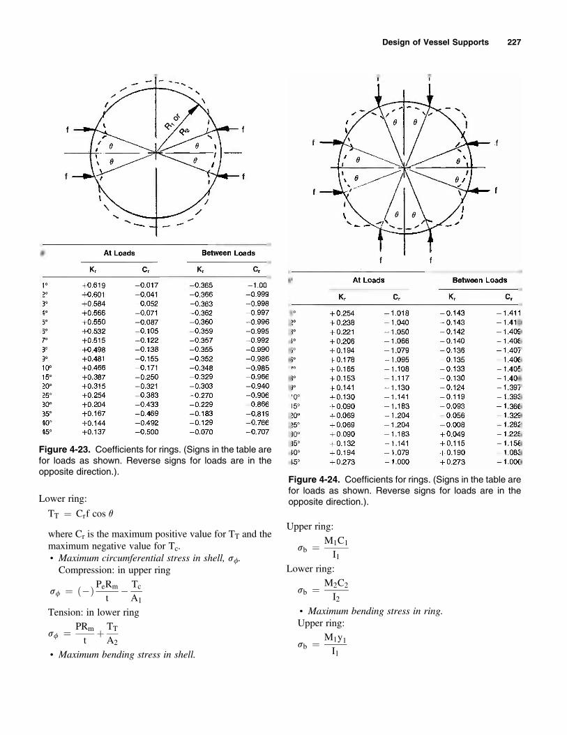
Lower ring
TT frac14 Crf cos q
where Cr is the maximum positive value for TT and themaximum negative value for Tcbull Maximum circumferential stress in shell sfCompression in upper ring
sf frac14 ethTHORN PeRm
t Tc
A1
Tension in lower ring
sf frac14 PRm
tthorn TT
A2
bull Maximum bending stress in shell
Upper ring
sb frac14 M1C1
I1Lower ring
sb frac14 M2C2
I2bull Maximum bending stress in ringUpper ring
sb frac14 M1y1I1
Figure 4-23 Coefficients for rings (Signs in the table arefor loads as shown Reverse signs for loads are in theopposite direction)
Figure 4-24 Coefficients for rings (Signs in the table arefor loads as shown Reverse signs for loads are in theopposite direction)
Design of Vessel Supports 227
Figure 4-25 Properties of upper ring
Figure 4-26 Properties of lower ring
Figure 4-27 Determining the thickness of the lower ringto resist bending
Table 4-16Maximum bending moments in a bearing plate with gussets
lsquo
bMx
x[ 05by[ lsquo
Mx
x[ 05by[0
0 0 ()0500 Bpl2
0333 00078 Bp b2 ()0428 Bpl
2
05 00293 Bp b2 ()0319 Bpl
2
0666 00558 Bp b2 ()0227 Bpl
2
10 00972 Bp b2 ()0119 BPl
2
15 01230 Bp b2 ()0124 Bpl
2
20 01310 Bp b2 ()0125 BPl
2
30N 01330 Bp b2 ()0125 BPl
2
Reprinted by permission of John Wiley amp Sons Inc
From Process Equipment Design Table 103 (See Note 2)
228 Pressure Vessel Design Manual
bull Properties of upper ringbull Properties of lower ring
Lower ring
sb frac14 M2y2I2
bull Thickness of lower ring to resist bendingBearing area AbAb frac14
Bearing pressure Bp
Bp frac14 QAb
From Table 4-16 select the equation for the maximumbending moment in the bearing plate Use the greater ofMx or My
lsquo
bfrac14
Mb frac14Minimum thickness of lower ring tb
tb frac14ffiffiffiffiffiffiffiffiffi6Mb
S
r
Notes
1 Rings may induce high localized stresses in shellimmediately adjacent to rings
2 When lb 15 the maximum bending momentoccurs at the junction of the ring and shell Whenlbgt 15 the maximum bending moment occurs atthe middle of the free edge
3 Since the mean radius of the rings may be unknownat the beginning of computations yet is required fordetermining maximum bending moment substituteRm as a satisfactory approximation at that stage
4 The following values may be estimatedbull Ring thickness The thickness of each ring isarbitrary and can be selected by the designer Asuggested value is
tb frac14 03
ffiffiffiffiffiffiffiffiffiffiffiMmax
S3
r
bull Ring spacing Ring spacing is arbitrary and can beselected by the designer A suggested minimumvalue is
h frac14 B D
bull Ring depth The depth of ring cannot be computeddirectly but must be computed by successiveapproximations As a first trial
d frac14 21
ffiffiffiffiffiffiffiffiffiffiffiMmax
trS
r
Procedure 4-7 Seismic Design ndash Vessel on Lugs [58ndash13]
Notation
Rm frac14 center line radius of shell inN frac14 number of equally spaced lugsW frac14 weight of vessel plus contents lbf frac14 radial load lb
Fh frac14 horizontal seismic force lbFv frac14 vertical seismic force lbVh frac14 horizontal shear per lug lbVv frac14 vertical shear per lug lbQ frac14 vertical load on lugs lb
g b frac14 coefficientsMc frac14 external circumferential moment inndashlbML frac14 external longitudinal moment in-lb
Mf frac14 internal bending moment circumferentialin-lbin
Mx frac14 internal bending moment longitudinal in -lbin
Nf frac14 membrane force in shell circumferential lbin
Nx frac14 membrane force in shell longitudinal lbinP frac14 internal pressure psiCh frac14 horizontal seismic factorCv frac14 vertical seismic factor
CcCi frac14 multiplication factors for Nf and Nx forrectangular attachments
KCK1 frac14 coefficients for determining b for momentloads on rectangular areas
Design of Vessel Supports 229
K1K2 frac14 coefficients for determining b for radial loadson rectangular areas
KnKb frac14 stress concentration factors (see Note 5)sf frac14 circumferential stress psisx frac14 longitudinal stress psits frac14 thickness of shell intp frac14 thickness of reinforcing pad ina frac14 coefficient of thermal expansion inindegFz frac14 radial deflection in
Neutralaxis
ML
Rm
bVh
a
Q1 Inner Outer
aQ3
Neutralaxis
bVh
ML = Q3a ndash VhbM1 = Q1a + Vhb
C
Figure 4-28 Dimensions and forces for support lug
OuterIug
Q1Q3
Fv
Fh
Fv
cg L
B
Innerlug
Neutralaxis
Figure 4-29 Case 1 Lugs below the center of gravity
InnerIug
Outerlug
Neutralaxis
B
LQ1
Q3
FvFh
Fv
cg
Figure 4-30 Case 2 Lugs above the center of gravity
00
90deg90deg
180deg
270deg270deg
b
2C12C1
2C2
2C2
b
Figure 4-31 Area of loading
L3
L3
L4
L4
F2
F2
F1
F1
LOSAA
A ALOS
Mmax = GREATER OF
Vmax = Greater of F1 or F2
MAA = F1 L3
Or F2 L4
LOWER PORTION
GOVERNS
UPPER PORTION
GOVERNS
Figure 4-32 Vessel supported on lugs (Influence ofsupport positioning)
230 Pressure Vessel Design Manual
Design of Vessel Supports 231
Table 4-18Coefficients for longitudinal moment ML
b1b2 g CL for Nf CL for Nx KL for Mf KL for Mx
15 075 043 180 124
50 077 033 165 116
025 100 080 024 159 111
200 085 010 158 111
300 090 007 156 111
15 090 076 108 104
50 093 073 107 103
05 100 097 068 106 102
200 099 064 105 102
300 110 060 105 102
15 089 100 101 108
50 089 096 100 107
1 100 089 092 098 105
200 089 099 095 101
300 095 105 092 096
15 087 130 094 112
50 084 123 092 110
2 100 081 115 089 107
200 080 133 084 099
300 080 150 079 091
15 068 120 090 124
50 061 113 086 119
4 100 051 103 081 112
200 050 118 073 098
300 050 133 064 083
Reprinted by permission of the Welding Research Council
Table 4-17Coefficients for circumferential moment Mc
b1b2 g Cc for Nf Cc for Nx Kc for Mf Kc for Mx
15 031 049 131 184
50 021 046 124 162
025 100 015 044 116 145
200 012 045 109 131
300 009 046 102 117
15 064 075 109 136
50 057 075 108 131
05 100 051 076 104 116
200 045 076 102 120
300 039 077 099 113
15 117 108 115 117
50 109 103 112 114
1 100 097 094 107 110
200 091 091 104 106
300 085 089 099 102
15 170 130 120 097
50 159 123 116 096
2 100 143 112 110 095
200 137 106 105 093
300 130 100 100 090
15 175 131 147 108
50 164 111 143 107
4 100 149 081 138 106
200 142 078 133 102
300 136 074 127 098
Reprinted by permission of the Welding Research Council
232 Pressure Vessel Design Manual
Analysis when Reinforcing Pads are Used
Step 1 Compute radial loads f
Step 3 Compute equivalent b values
Step 2 Compute geometric parameters
Figure 4-33 Dimensions of load areas for radial loads
Case 1 Case 2 Case 3
Outer f1 frac14 3ML1
4C2f1 frac14 3ML1
4C2
Sides f2 frac14 3ML2
4C2f2 frac14 3ML2
4C2
Inner f3 frac14 3ML3
4C2f3 frac14 3ML3
4C2
Table 4-19
Four values of b are computed for use in
determining Nf Nx Mf and Mx as follows The values of K1 and K2 are taken from Table 4-19 Values of coefficient K1 and K2
b1b2 Dagger 1 b K1 K2
b frac14 frac121 1
3ethb1b2
1THORNeth1 k1THORNffiffiffiffiffiffiffiffiffiffib1b2
pba for Nf frac14 Nf 091 148
bb for Nxfrac14 Nx 168 12
b1b2 lt 1
b frac14 frac121 4
3eth1 b1
b2THORNeth1 k2THORN
ffiffiffiffiffiffiffiffiffiffiffiffiffib1=b2
pbc for Mf frac14 Mf 176 088
bd for Mx frac14 Mx 12 125
Reprinted by permission of the Welding Research Council
At Edge of Attachment At Edge of Pad
Rm frac14 IDthorn ts thorn tp2
Rm frac14 IDthorn ts2
t frac14ffiffiffiffiffiffiffiffiffiffiffiffiffit2s thorn t2p
qt frac14 ts
g frac14 Rm=t g frac14 Rm=t
b1 frac14 C1=Rm b1 frac14 d1=Rm
b2 frac14 4C2=3Rm b2 frac14 d2=Rm
b1=b2 b1=b2
Design of Vessel Supports 233
Step 4 Compute stresses for a radial load
Radial Load Figure b Values from Figure Forces and Moments Stress
Membrane 7-21A ba frac14 NfRm
ffrac14 eth THORN Nf frac14 eth THORNf
Rmfrac14 sf frac14 KnNf
tfrac14
7-21B bb frac14 NxRm
ffrac14 eth THORN Nx frac14 eth THORNf
Rmfrac14 sx frac14 KnNx
tfrac14
Bending 7-22A bc frac14 Mf
ffrac14 eth THORN Mf frac14 eth THORNf frac14 sf frac14 6KbMf
t2frac14
7-22B bd frac14 Mx
ffrac14 eth THORN Mx frac14 eth THORNf frac14 sx frac14 6KbMx
t2frac14
234 Pressure Vessel Design Manual
Figure 4-34 Radial loads F and f
Design of Vessel Supports 235
7
7
B
Fh
Case 1 Load through lugs
Case 2 Load between lugs
Fh
V7
V7
V8
V8
Φ1 = 0
Φ2 = 45ordm
Φ3 = 90ordm
Φ4 = 135ordm
Φ5 = 180ordm
Φ1 = 225ordm
Φ2 = 675ordm
Φ3 = 1125ordm
Φ4 = 1575ordm
V1
V1
V2
V2
B1
V3
V3
V4
V4
V5
V5
V6
V6
8
8
6
6
5
5
4
4
3
3
2
2
1
1
Φ2
Φ2
Φ1
Φ3
Φ3
Φ4
Φ4
Φ5
Figure 4-35 Vessel supported on (8) lugs
236 Pressure Vessel Design Manual
Design of Vessel Supported on (8) Lugs
Item Formula Calculation
Lateral Force Fh frac14 Ch W
Horizontal ShearLug Vh frac14 Fh N
Vertical Force FV frac14 ( 1 thorn CV ) W
Overturning Moment M frac14 Fh L
Dead LoadLug VV frac14 FV N
Worst Case Vertical Live Load per Lug FL frac14 4 M N B
VERTICAL LIVE LOAD ON EACH LUG FLn
LUG CASE 1 CASE 2
1 FL 924 FL
2 707 FL 383 FL
3 0 thorn 383 FL
4 thorn707 FL thorn 924 FL
5 thorn FL thorn 924 FL
6 707 FL thorn 383 FL
7 0 383 FL
8 thorn 707 FL 924 FL
Formulas in Table are based on the following equations
CASE 1 FL frac14 4 M cosfn N B
CASE 2 FL frac14 4 M cosfn N B1
Vertical Load on any Lug Qn frac14 VV thorn FLn
Worst Case Load per Lug Q frac14 VV thorn FL
Longitudinal Moment for any Given Lug MLn frac14 Qn a thorn- Vh b
Longitudinal Moment for any Worst Case ML frac14 Q a thorn- Vh b
Design of Vessel Supported on (8) Lugs (Example) Data
ITEM FORMULA CALCULATION Ch frac14 1
Lateral Force Fh frac14 Ch W Fh frac14 1 (141K ) frac14 141K CV frac14 2
Horizontal ShearLug Vh frac14 Fh N Vh frac14 141K 8 frac14 176K W frac14 141K
Vertical Force FV frac14 ( 1 thorn CV ) W FV frac14 (1 thorn 2 ) 141K frac14 1692K L frac14 84
Overturning Moment M frac14 Fh L M frac14 141K (84) frac14 1184 In-Kips a frac14 12
Dead LoadLug VV frac14 FV N VV frac14 1692K 8 frac14 2115K b frac14 624
Worst Case Vertical Live Load per Lug FL frac14 4 M N B FL frac14 4(1184K ) (8) 16025 frac14 369K B frac14 16025
B1 frac14 11331
VERTICAL LIVE LOAD ON EACH LUG FLn
LUG CASE 1 CASE 2
1 FL 924 FL
2 707 FL 383 FL
3 0 thorn 383 FL
4 thorn707 FL thorn 924 FL
5 thorn FL thorn 924 FL
6 707 FL thorn 383 FL
7 0 383 FL
8 thorn 707 FL 924 FL
Formulas in Table are based on the following equations
CASE 1 FL frac14 4 M cosfn N B
CASE 2 FL frac14 4 M cosfn N B1
Vertical Load on any Lug Qn frac14 VV thorn FLn
Worst Case Load per Lug Q frac14 VV thorn FL Q frac14 2115 thorn 369 frac14 2484K
Longitudinal Moment for any Given Lug MLn frac14 Qn a thorn- Vh b
Longitudinal Moment for any Worst Case ML frac14 Q a thorn- Vh b ML frac14 2484K (12) thorn 176K (624) frac14 309 in-Kips
Design of Vessel Supports 237
Check lug for radial thermal expansion zr
DT frac14 Design temperature oFR frac14 Radius frac14 B 2a frac14 Coefficient of thermal expansion inin oF
DT frac14 Change in temperature from 70 oF
zr frac14 a DT R frac14
Example
R frac14 80125 in
DT frac14 925Fa frac14 79
106 in=in=F
DT frac14 925 70 frac14 855Fzr frac14 79
106 855 80125 frac14 541 in
Use slotted holes
Size of anchor bolts Required Ar
Due to Overturning Moment
Ar frac14 frac12eth4 M=BTHORN Wfrac121=ethNb SbTHORN
Nb frac14 Number of anchor boltsIf Ar is negative there is no uplift
Due to Shear
Shear lug fSfS frac14 Fh=Nb
Ar frac14 fS=FS
Use minimum size of anchor bolts of 075 in diameter
Notes
1 A change in location of the cg for various oper-ating levels can greatly affect the moment at lugsby increasing or decreasing the ldquoLrdquo dimensionDifferent levels and weights should be investigatedfor determining worst case (ie full half-fullempty etc)
2 This procedure ignores effects of sliding frictionbetween lugs and beams during heatingcoolingcycles These effects will be negligible forsmall-diameter vessels relatively low operating
temperatures or where slide plates are used toreduce friction forces Other cases should beinvestigated
3 Since vessels supported on lugs are commonlylocated in structures the earthquake effects will bedependent on the structure as well as on the vesselThus horizontal and vertical seismic factors mustbe provided
4 If reinforcing pads are used to reduce stresses in theshell or a design that uses them is being checkedthen Bijlaard recommends an analysis that convertsmoment loadings into equivalent radial loads Theattachment area is reduced about two-thirdsStresses at the edge of load area and stresses at theedge of the pad must be checked See ldquoAnalysisWhen Reinforcing Pads are Usedrdquo
5 Stress concentration factors are found in theprocedure on local stresses
6 To determine the area of attachment see ldquoAttach-ment Parametersrdquo Please note that if a top(compression) plate is not used then an equivalentrectangle that is equal to the moment of inertia ofthe attachment and whose width-to-height ratio isthe same must be determined The neutral axis isthe rotating axis of the lug passing through thecentroid
7 Stiffening effects due to proximity to major stiff-ening elements though desirable have beenneglected in this procedure
8 Assume effects of radial loads as additive to thosedue to internal pressure even though the loadingsmay be in the opposite directions Althoughconservative they will account for the highdiscontinuity stresses immediately adjacent to thelugs
9 In general the smaller the diameter of the vesselthe further the distribution of stresses in thecircumferential direction In small diametervessels the longitudinal stresses are confined toa narrow band The opposite becomes true forlarger-diameter vessels or larger Rmt ratios
10 If shell stresses are excessive the followingmethods may be utilized to reduce the stressesa Add more lugsb Add more gussetsc Increase angle q between gussetsd Increase height of lugs he Add reinforcing pads under lugs
238 Pressure Vessel Design Manual
f Increase thickness of shell course to which lugsare attached
g Add top and bottom plates to lugs or increasewidth of plates
h Add circumferential ring stiffeners at top andbottom of lugs
Procedure 4-8 Seismic Design ndash Vessel on Skirt [123]
Notation
T frac14 period of vibration secSI frac14 code allowable stress tension psiH frac14 overall height of vessel from bottom of base
plate fthx frac14 height from base to center of section or eg
of a concentrated load fthi frac14 height from base to plane under consider-
ation fta b g frac14 coefficients from Table 4-20 for given plane
based on hxHWx frac14 total weight of section kipsW frac14 weight of concentrated load or mass kipsWo frac14 total weight of vessel operating kipsWh frac14 total weight of vessel above the plane under
consideration kipswx frac14 uniformly distributed load for each section
kipsftFx frac14 lateral force applied at each section kipsV frac14 base shear kipsVx frac14 shear at plane x kipsMx frac14 moment at plane x ft-kipsMb frac14 overturning moment at base ft-kipsD frac14 mean shell diameter of each section ft or inE frac14 modulus of elasticity at design temperature
106 psiEl frac14 joint efficiencyt frac14 thickness of vessel section inPi frac14 internal design pressure psiPe frac14 external design pressure psi
Da Dg frac14 difference in values of a and g from top tobottom of any given section
lx frac14 length of section ftsxt frac14 longitudinal stress tension psisxc frac14 longitudinal stress compression psiRo frac14 outside radius of vessel at plane under
consideration inA frac14 code factor for determining allowable
compressive stress B
B frac14 code allowable compressive stress psiF frac14 lateral seismic force for uniform vessel kipsCh frac14 horizontal seismic factor
Cases
Case 1 Uniform Vessels For vessels of uniform crosssection without concentrated loads (ie reboilerspacking large liquid sections etc) weight can beassumed to be uniformly distributed over the entireheight
Wo frac14H frac14D frac14t frac14
T frac14 00000265
HD
2ffiffiffiffiffiffiffiffiffiffiWoDHt
r
Note POV may be determined from chart in Figure4-6 H and D are in feet t is in inches
V frac14 ChWo
F frac14 V
Mb frac14 2=3ethFHTHORN
Moment at any height hj
Ma frac14 F
2H3
hi
Case 2 Nonuniform VesselsProcedure for finding period of vibration moments
and forces at various planes for nonuniform vesselsA nonuniform vertical vessel is one that varies in
diameter thickness or weight at different elevations Thisprocedure distributes the seismic forces and thus baseshear along the column in proportion to the weights of
Design of Vessel Supports 239
each section The results are a more accurate and realisticdistribution of forces and accordingly a more accurateperiod of vibration The procedure consists of two mainsteps
Step 1 Determination of period of vibration (POV) TDivide the column into sections of uniform weight anddiameter not to exceed 20 of the overall height Auniform weight is calculated for each section Diameterand thicknesses are taken into account through factorsa and g Concentrated loads are handled as separatesections and not combined with other sections Factor
b will proportion effects of concentrated loads Thecalculation form is completed for each section from leftto right then totaled to the bottom These totals are usedto determine T (POV) and the POV in turn is usedto determine V and Ft
Step 2 Determination of forces shears and momentsAgain the vessel is divided into major sections as inStep 1 however longer sections should be furthersubdivided into even increments For these calcula-tions sections should not exceed 10 of heightRemember the moments and weights at each planewill be used in determining what thicknesses arerequired It is convenient to work in 8 to 10 footincrements to match shell courses Piping traysplatforms insulation fireproofing and liquid weightsshould be added into the weights of each section wherethey occur Overall weights of sections are used indetermining forces not uniform weights Momentsdue to eccentric loads are added to the overall momentof the column
Notes for nonuniform vessels
1 Combine moments with corresponding weights ateach section and use allowable stresses to deter-mine required shell and skirt thicknesses at theelevation
2P
uDa and WbH are separate totals and arecombined in computation of POV
3 (D10)3 is used in this expression if kips are usedUse (D)3 if lb are used
4 For vessels having a lower section several times thediameter of the upper portion and where the lowerportion is short compared to the overall height thePOV can more accurately be determined bvfinding the POV of the upper section alone (seeFigure 438a)
5 For vessels where Rt is large in comparison tothe supporting skirt the POV calculated bythis method may be overly conservative Moreaccurate methods may be employed (seeFigure 438b)
6 Make sure to add moment due to any eccentric loadsto total moment
Figure 4-36 Typical dimensional data forces andloadings on a uniform vessel supported on a skirt (d frac14deflection)
240 Pressure Vessel Design Manual
Figure 4-37 Nonuniform vessel illustrating a) Note 4 andb) Note 5
Figure 4-38 Typical dimensional data forces andloadings on a nonuniform vessel supported on a skirt
Design of Vessel Supports 241
Step 1 PERIOD OF VIBRATION
Partω or W
kft hxH α Δα or βωΔα or WβH γ Δγ
10 2103 10
000Σ =
See Notes 2 and 3
γtΔ310HWβωΔα2
100HT
sumE(D )sum+sum= ⎟
⎠⎞⎜
⎝⎛
E(D10)3tΔγ Note 3
Σ =
242 Pressure Vessel Design Manual
Step 1 PERIOD OF VIBRATION EXAMPLE
INC
LUD
E BO
TTO
M H
EAD
AN
D L
IQU
ID A
S PA
RT
3
H =
112
primendash0Prime
10primendash
0Prime 20primendash
0Prime
40primendash
0Prime16
primendash0Prime
20 T
RAY
S
2primendash
0Prime S
PAC
ING
= 4
2primendash0
Prime
8primendash0Prime 12Prime THK
38PrimeTHK
REB
OIL
ERw
=10
KPS
LIQ
UID
2prime2prime
Design of Vessel Supports 243
Step 2 SHEAR AND MOMENTS
244 Pressure Vessel Design Manual
Step 2 SHEAR AND MOMENTS EXAMPLE
hi (ft) Part Wx (kips) hx (ft)
Wxhx (ft-
kips) Fx (kips)
Vi btm
(kips) Mi (kips)0211211
12 1416 106 1501 732
100 732 4392
11 118 95 1121 54790 1279 14444
10 118 85 1003 48980 1768 29676
9 118 75 885 43270 2199 49511
8 826 65 537 26260 2461 72813
7 59 55 325 15850 2619 98215
6 278 45 1251 61040 3229 127458
5 278 35 973 47430 3704 162125
4 278 25 695 33920 3 10 20 200 098
4140 2008582 278 15 417 203
10 4344 243278
1 875 5 44 02112868256340
= = 194 8951
k = 1 for structures with periods of 05 seconds or lessk = 2 for structures with periods of 25 seconds or morek shall be linearly interpolated with perdiods between 05 and 25 seconds
1iM)ih1i(h1iV)ihx(hxFiM ++minus+++minus=
⎟⎟⎠
⎞⎜⎜⎝
⎛
sum= k
xhxWkxhxW
VxF ⎟⎟⎠
⎞⎜⎜⎝
⎛= kxhxW
8951
4365xF
0 0
12rsquondash
0rdquo10
rsquondash0rdquo
10rsquondash
0rdquo10
rsquondash0rdquo
10rsquondash
0rdquo10
rsquondash0rdquo
10rsquondash
0rdquo10
rsquondash0rdquo
H =
112
rsquondash0rdquo
10rsquondash
0rdquo10
rsquondash0rdquo
10rsquondash
0rdquo
Design of Vessel Supports 245

7
7
B
Fh
Case 1 Load through lugs
Case 2 Load between lugs
Fh
V7
V7
V8
V8
Φ1 = 0
Φ2 = 45ordm
Φ3 = 90ordm
Φ4 = 135ordm
Φ5 = 180ordm
Φ1 = 225ordm
Φ2 = 675ordm
Φ3 = 1125ordm
Φ4 = 1575ordm
V1
V1
V2
V2
B1
V3
V3
V4
V4
V5
V5
V6
V6
8
8
6
6
5
5
4
4
3
3
2
2
1
1
Φ2
Φ2
Φ1
Φ3
Φ3
Φ4
Φ4
Φ5
Figure 4-35 Vessel supported on (8) lugs
236 Pressure Vessel Design Manual
Design of Vessel Supported on (8) Lugs
Item Formula Calculation
Lateral Force Fh frac14 Ch W
Horizontal ShearLug Vh frac14 Fh N
Vertical Force FV frac14 ( 1 thorn CV ) W
Overturning Moment M frac14 Fh L
Dead LoadLug VV frac14 FV N
Worst Case Vertical Live Load per Lug FL frac14 4 M N B
VERTICAL LIVE LOAD ON EACH LUG FLn
LUG CASE 1 CASE 2
1 FL 924 FL
2 707 FL 383 FL
3 0 thorn 383 FL
4 thorn707 FL thorn 924 FL
5 thorn FL thorn 924 FL
6 707 FL thorn 383 FL
7 0 383 FL
8 thorn 707 FL 924 FL
Formulas in Table are based on the following equations
CASE 1 FL frac14 4 M cosfn N B
CASE 2 FL frac14 4 M cosfn N B1
Vertical Load on any Lug Qn frac14 VV thorn FLn
Worst Case Load per Lug Q frac14 VV thorn FL
Longitudinal Moment for any Given Lug MLn frac14 Qn a thorn- Vh b
Longitudinal Moment for any Worst Case ML frac14 Q a thorn- Vh b
Design of Vessel Supported on (8) Lugs (Example) Data
ITEM FORMULA CALCULATION Ch frac14 1
Lateral Force Fh frac14 Ch W Fh frac14 1 (141K ) frac14 141K CV frac14 2
Horizontal ShearLug Vh frac14 Fh N Vh frac14 141K 8 frac14 176K W frac14 141K
Vertical Force FV frac14 ( 1 thorn CV ) W FV frac14 (1 thorn 2 ) 141K frac14 1692K L frac14 84
Overturning Moment M frac14 Fh L M frac14 141K (84) frac14 1184 In-Kips a frac14 12
Dead LoadLug VV frac14 FV N VV frac14 1692K 8 frac14 2115K b frac14 624
Worst Case Vertical Live Load per Lug FL frac14 4 M N B FL frac14 4(1184K ) (8) 16025 frac14 369K B frac14 16025
B1 frac14 11331
VERTICAL LIVE LOAD ON EACH LUG FLn
LUG CASE 1 CASE 2
1 FL 924 FL
2 707 FL 383 FL
3 0 thorn 383 FL
4 thorn707 FL thorn 924 FL
5 thorn FL thorn 924 FL
6 707 FL thorn 383 FL
7 0 383 FL
8 thorn 707 FL 924 FL
Formulas in Table are based on the following equations
CASE 1 FL frac14 4 M cosfn N B
CASE 2 FL frac14 4 M cosfn N B1
Vertical Load on any Lug Qn frac14 VV thorn FLn
Worst Case Load per Lug Q frac14 VV thorn FL Q frac14 2115 thorn 369 frac14 2484K
Longitudinal Moment for any Given Lug MLn frac14 Qn a thorn- Vh b
Longitudinal Moment for any Worst Case ML frac14 Q a thorn- Vh b ML frac14 2484K (12) thorn 176K (624) frac14 309 in-Kips
Design of Vessel Supports 237
Check lug for radial thermal expansion zr
DT frac14 Design temperature oFR frac14 Radius frac14 B 2a frac14 Coefficient of thermal expansion inin oF
DT frac14 Change in temperature from 70 oF
zr frac14 a DT R frac14
Example
R frac14 80125 in
DT frac14 925Fa frac14 79
106 in=in=F
DT frac14 925 70 frac14 855Fzr frac14 79
106 855 80125 frac14 541 in
Use slotted holes
Size of anchor bolts Required Ar
Due to Overturning Moment
Ar frac14 frac12eth4 M=BTHORN Wfrac121=ethNb SbTHORN
Nb frac14 Number of anchor boltsIf Ar is negative there is no uplift
Due to Shear
Shear lug fSfS frac14 Fh=Nb
Ar frac14 fS=FS
Use minimum size of anchor bolts of 075 in diameter
Notes
1 A change in location of the cg for various oper-ating levels can greatly affect the moment at lugsby increasing or decreasing the ldquoLrdquo dimensionDifferent levels and weights should be investigatedfor determining worst case (ie full half-fullempty etc)
2 This procedure ignores effects of sliding frictionbetween lugs and beams during heatingcoolingcycles These effects will be negligible forsmall-diameter vessels relatively low operating
temperatures or where slide plates are used toreduce friction forces Other cases should beinvestigated
3 Since vessels supported on lugs are commonlylocated in structures the earthquake effects will bedependent on the structure as well as on the vesselThus horizontal and vertical seismic factors mustbe provided
4 If reinforcing pads are used to reduce stresses in theshell or a design that uses them is being checkedthen Bijlaard recommends an analysis that convertsmoment loadings into equivalent radial loads Theattachment area is reduced about two-thirdsStresses at the edge of load area and stresses at theedge of the pad must be checked See ldquoAnalysisWhen Reinforcing Pads are Usedrdquo
5 Stress concentration factors are found in theprocedure on local stresses
6 To determine the area of attachment see ldquoAttach-ment Parametersrdquo Please note that if a top(compression) plate is not used then an equivalentrectangle that is equal to the moment of inertia ofthe attachment and whose width-to-height ratio isthe same must be determined The neutral axis isthe rotating axis of the lug passing through thecentroid
7 Stiffening effects due to proximity to major stiff-ening elements though desirable have beenneglected in this procedure
8 Assume effects of radial loads as additive to thosedue to internal pressure even though the loadingsmay be in the opposite directions Althoughconservative they will account for the highdiscontinuity stresses immediately adjacent to thelugs
9 In general the smaller the diameter of the vesselthe further the distribution of stresses in thecircumferential direction In small diametervessels the longitudinal stresses are confined toa narrow band The opposite becomes true forlarger-diameter vessels or larger Rmt ratios
10 If shell stresses are excessive the followingmethods may be utilized to reduce the stressesa Add more lugsb Add more gussetsc Increase angle q between gussetsd Increase height of lugs he Add reinforcing pads under lugs
238 Pressure Vessel Design Manual
f Increase thickness of shell course to which lugsare attached
g Add top and bottom plates to lugs or increasewidth of plates
h Add circumferential ring stiffeners at top andbottom of lugs
Procedure 4-8 Seismic Design ndash Vessel on Skirt [123]
Notation
T frac14 period of vibration secSI frac14 code allowable stress tension psiH frac14 overall height of vessel from bottom of base
plate fthx frac14 height from base to center of section or eg
of a concentrated load fthi frac14 height from base to plane under consider-
ation fta b g frac14 coefficients from Table 4-20 for given plane
based on hxHWx frac14 total weight of section kipsW frac14 weight of concentrated load or mass kipsWo frac14 total weight of vessel operating kipsWh frac14 total weight of vessel above the plane under
consideration kipswx frac14 uniformly distributed load for each section
kipsftFx frac14 lateral force applied at each section kipsV frac14 base shear kipsVx frac14 shear at plane x kipsMx frac14 moment at plane x ft-kipsMb frac14 overturning moment at base ft-kipsD frac14 mean shell diameter of each section ft or inE frac14 modulus of elasticity at design temperature
106 psiEl frac14 joint efficiencyt frac14 thickness of vessel section inPi frac14 internal design pressure psiPe frac14 external design pressure psi
Da Dg frac14 difference in values of a and g from top tobottom of any given section
lx frac14 length of section ftsxt frac14 longitudinal stress tension psisxc frac14 longitudinal stress compression psiRo frac14 outside radius of vessel at plane under
consideration inA frac14 code factor for determining allowable
compressive stress B
B frac14 code allowable compressive stress psiF frac14 lateral seismic force for uniform vessel kipsCh frac14 horizontal seismic factor
Cases
Case 1 Uniform Vessels For vessels of uniform crosssection without concentrated loads (ie reboilerspacking large liquid sections etc) weight can beassumed to be uniformly distributed over the entireheight
Wo frac14H frac14D frac14t frac14
T frac14 00000265
HD
2ffiffiffiffiffiffiffiffiffiffiWoDHt
r
Note POV may be determined from chart in Figure4-6 H and D are in feet t is in inches
V frac14 ChWo
F frac14 V
Mb frac14 2=3ethFHTHORN
Moment at any height hj
Ma frac14 F
2H3
hi
Case 2 Nonuniform VesselsProcedure for finding period of vibration moments
and forces at various planes for nonuniform vesselsA nonuniform vertical vessel is one that varies in
diameter thickness or weight at different elevations Thisprocedure distributes the seismic forces and thus baseshear along the column in proportion to the weights of
Design of Vessel Supports 239
each section The results are a more accurate and realisticdistribution of forces and accordingly a more accurateperiod of vibration The procedure consists of two mainsteps
Step 1 Determination of period of vibration (POV) TDivide the column into sections of uniform weight anddiameter not to exceed 20 of the overall height Auniform weight is calculated for each section Diameterand thicknesses are taken into account through factorsa and g Concentrated loads are handled as separatesections and not combined with other sections Factor
b will proportion effects of concentrated loads Thecalculation form is completed for each section from leftto right then totaled to the bottom These totals are usedto determine T (POV) and the POV in turn is usedto determine V and Ft
Step 2 Determination of forces shears and momentsAgain the vessel is divided into major sections as inStep 1 however longer sections should be furthersubdivided into even increments For these calcula-tions sections should not exceed 10 of heightRemember the moments and weights at each planewill be used in determining what thicknesses arerequired It is convenient to work in 8 to 10 footincrements to match shell courses Piping traysplatforms insulation fireproofing and liquid weightsshould be added into the weights of each section wherethey occur Overall weights of sections are used indetermining forces not uniform weights Momentsdue to eccentric loads are added to the overall momentof the column
Notes for nonuniform vessels
1 Combine moments with corresponding weights ateach section and use allowable stresses to deter-mine required shell and skirt thicknesses at theelevation
2P
uDa and WbH are separate totals and arecombined in computation of POV
3 (D10)3 is used in this expression if kips are usedUse (D)3 if lb are used
4 For vessels having a lower section several times thediameter of the upper portion and where the lowerportion is short compared to the overall height thePOV can more accurately be determined bvfinding the POV of the upper section alone (seeFigure 438a)
5 For vessels where Rt is large in comparison tothe supporting skirt the POV calculated bythis method may be overly conservative Moreaccurate methods may be employed (seeFigure 438b)
6 Make sure to add moment due to any eccentric loadsto total moment
Figure 4-36 Typical dimensional data forces andloadings on a uniform vessel supported on a skirt (d frac14deflection)
240 Pressure Vessel Design Manual
Figure 4-37 Nonuniform vessel illustrating a) Note 4 andb) Note 5
Figure 4-38 Typical dimensional data forces andloadings on a nonuniform vessel supported on a skirt
Design of Vessel Supports 241
Step 1 PERIOD OF VIBRATION
Partω or W
kft hxH α Δα or βωΔα or WβH γ Δγ
10 2103 10
000Σ =
See Notes 2 and 3
γtΔ310HWβωΔα2
100HT
sumE(D )sum+sum= ⎟
⎠⎞⎜
⎝⎛
E(D10)3tΔγ Note 3
Σ =
242 Pressure Vessel Design Manual
Step 1 PERIOD OF VIBRATION EXAMPLE
INC
LUD
E BO
TTO
M H
EAD
AN
D L
IQU
ID A
S PA
RT
3
H =
112
primendash0Prime
10primendash
0Prime 20primendash
0Prime
40primendash
0Prime16
primendash0Prime
20 T
RAY
S
2primendash
0Prime S
PAC
ING
= 4
2primendash0
Prime
8primendash0Prime 12Prime THK
38PrimeTHK
REB
OIL
ERw
=10
KPS
LIQ
UID
2prime2prime
Design of Vessel Supports 243
Step 2 SHEAR AND MOMENTS
244 Pressure Vessel Design Manual
Step 2 SHEAR AND MOMENTS EXAMPLE
hi (ft) Part Wx (kips) hx (ft)
Wxhx (ft-
kips) Fx (kips)
Vi btm
(kips) Mi (kips)0211211
12 1416 106 1501 732
100 732 4392
11 118 95 1121 54790 1279 14444
10 118 85 1003 48980 1768 29676
9 118 75 885 43270 2199 49511
8 826 65 537 26260 2461 72813
7 59 55 325 15850 2619 98215
6 278 45 1251 61040 3229 127458
5 278 35 973 47430 3704 162125
4 278 25 695 33920 3 10 20 200 098
4140 2008582 278 15 417 203
10 4344 243278
1 875 5 44 02112868256340
= = 194 8951
k = 1 for structures with periods of 05 seconds or lessk = 2 for structures with periods of 25 seconds or morek shall be linearly interpolated with perdiods between 05 and 25 seconds
1iM)ih1i(h1iV)ihx(hxFiM ++minus+++minus=
⎟⎟⎠
⎞⎜⎜⎝
⎛
sum= k
xhxWkxhxW
VxF ⎟⎟⎠
⎞⎜⎜⎝
⎛= kxhxW
8951
4365xF
0 0
12rsquondash
0rdquo10
rsquondash0rdquo
10rsquondash
0rdquo10
rsquondash0rdquo
10rsquondash
0rdquo10
rsquondash0rdquo
10rsquondash
0rdquo10
rsquondash0rdquo
H =
112
rsquondash0rdquo
10rsquondash
0rdquo10
rsquondash0rdquo
10rsquondash
0rdquo
Design of Vessel Supports 245
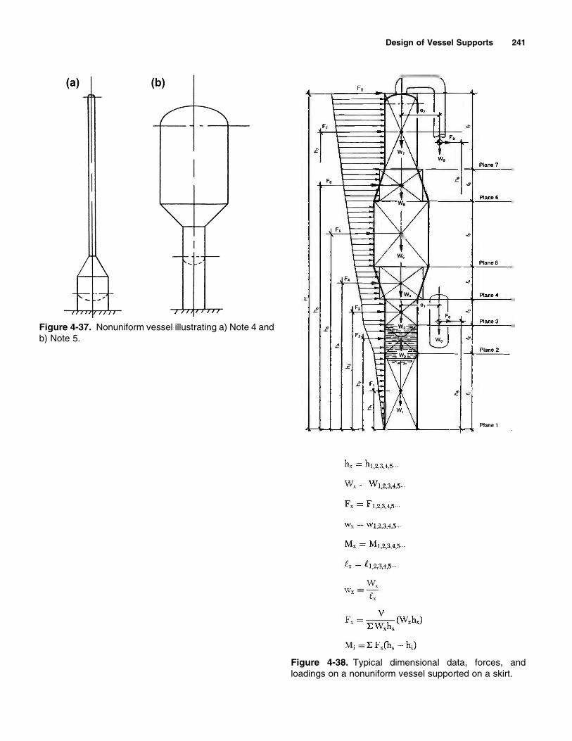


