University of Pennsylvania University of Pennsylvania ScholarlyCommons ScholarlyCommons Departmental Papers (ESE) Department of Electrical & Systems Engineering 2016 Design Principles for a Family of Direct-Drive Legged Robots Design Principles for a Family of Direct-Drive Legged Robots Gavin Kenneally University of Pennsylvania, [email protected]Avik De University of Pennsylvania Daniel E. Koditschek University of Pennsylvania, [email protected]Follow this and additional works at: https://repository.upenn.edu/ese_papers Part of the Applied Mechanics Commons, Electrical and Computer Engineering Commons, Electro- Mechanical Systems Commons, and the Systems Engineering Commons Recommended Citation Recommended Citation Gavin Kenneally, Avik De, and Daniel E. Koditschek, "Design Principles for a Family of Direct-Drive Legged Robots", IEEE Robotics and Automation Letters 1(2), 900-907. January 2016. http://dx.doi.org/10.1109/ LRA.2016.2528294 G. Kenneally, A. De and D. E. Koditschek, "Design Principles for a Family of Direct-Drive Legged Robots," in IEEE Robotics and Automation Letters, vol. 1, no. 2, pp. 900-907, July 2016. This paper is posted at ScholarlyCommons. https://repository.upenn.edu/ese_papers/705 For more information, please contact [email protected].
Transcript
University of Pennsylvania University of Pennsylvania
ScholarlyCommons ScholarlyCommons
Departmental Papers (ESE) Department of Electrical & Systems Engineering
2016
Design Principles for a Family of Direct-Drive Legged Robots Design Principles for a Family of Direct-Drive Legged Robots
Follow this and additional works at: https://repository.upenn.edu/ese_papers
Part of the Applied Mechanics Commons, Electrical and Computer Engineering Commons, Electro-
Mechanical Systems Commons, and the Systems Engineering Commons
Recommended Citation Recommended Citation Gavin Kenneally, Avik De, and Daniel E. Koditschek, "Design Principles for a Family of Direct-Drive Legged Robots", IEEE Robotics and Automation Letters 1(2), 900-907. January 2016. http://dx.doi.org/10.1109/LRA.2016.2528294
G. Kenneally, A. De and D. E. Koditschek, "Design Principles for a Family of Direct-Drive Legged Robots," in IEEE Robotics and Automation Letters, vol. 1, no. 2, pp. 900-907, July 2016.
This paper is posted at ScholarlyCommons. https://repository.upenn.edu/ese_papers/705 For more information, please contact [email protected].
Design Principles for a Family of Direct-Drive Legged Robots Design Principles for a Family of Direct-Drive Legged Robots
Abstract Abstract This letter introduces Minitaur, a dynamically running and leaping quadruped, which represents a novel class of direct-drive (DD) legged robots. We present a methodology that achieves the well-known benefits of DD robot design (transparency, mechanical robustness/efficiency, high-actuation bandwidth, and increased specific power), affording highly energetic behaviors across our family of machines despite severe limitations in specific force. We quantify DD drivetrain benefits using a variety of metrics, compare our machines' performance to previously reported legged platforms, and speculate on the potential broad-reaching value of “transparency” for legged locomotion.
Disciplines Disciplines Applied Mechanics | Electrical and Computer Engineering | Electro-Mechanical Systems | Engineering | Systems Engineering
Comments Comments G. Kenneally, A. De and D. E. Koditschek, "Design Principles for a Family of Direct-Drive Legged Robots," in IEEE Robotics and Automation Letters, vol. 1, no. 2, pp. 900-907, July 2016.
This journal article is available at ScholarlyCommons: https://repository.upenn.edu/ese_papers/705
IEEE ROBOTICS AND AUTOMATION LETTERS. PREPRINT VERSION. JANUARY, 2016 1
Design Principles for a Family of Direct-DriveLegged Robots
Gavin Kenneally1, Avik De2, and D. E. Koditschek2
Abstract—This paper introduces Minitaur, a dynamically run-ning and leaping quadruped, which represents a novel classof direct-drive (DD) legged robots. We present a methodologythat achieves the well known benefits of DD robot design(transparency, mechanical robustness / efficiency, high actuationbandwidth, increased specific power), affording highly energeticbehaviors across our family of machines despite severe limitationsin specific force. We quantify DD drivetrain benefits using a vari-ety of metrics, compare our machines’ performance to previouslyreported legged platforms, and speculate on the potential broad-reaching value of “transparency” for legged locomotion.
Index Terms—Multilegged Robots, Mechanism Design of Mo-bile Robots, Novel Actuators for Natural Machine Motion
I. INTRODUCTION
A direct-drive (DD) robot [1] forgoes the use of a gear,belt, chain, or other reduction to amplify its motors’
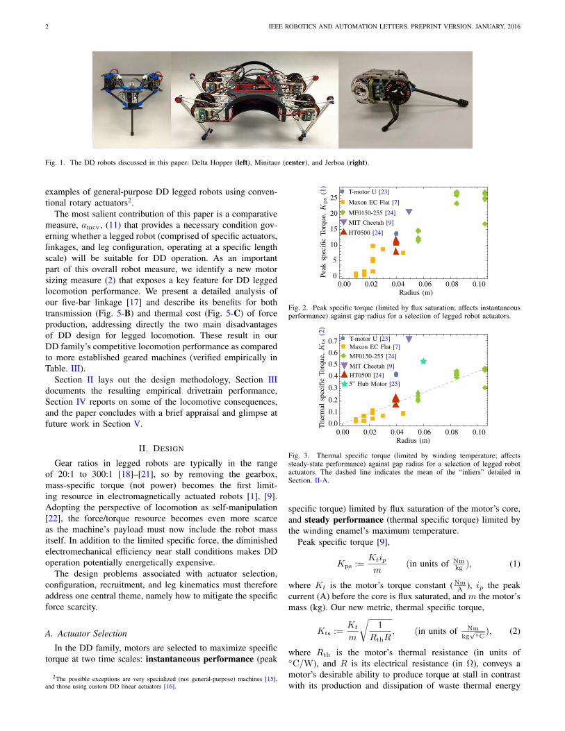
effective torque production. This is in contrast to other ac-tuation approaches used with electromagnetic motors such ashigh stiffness, large reduction geartrains typically found inhumanoid machines [2], and highly compliant series elasticactuators (SEA) [3]. In this paper we introduce a new classof DD legged platforms and present new design principlesthat underpin their effective operation1. This class includesMinitaur, a quadruped with two active DOF per leg (Fig. 1,center); Delta Hopper, a monoped with three active DOF perleg (Fig. 1, left); and Penn Jerboa, a tailed biped with oneactive DOF/leg, and compliant C-shaped legs (Fig. 1, right)[5]. These three robots share a common electromechanicalinfrastructure, demonstrating that the design principles detailedbelow can be successfully instantiated in very different mor-phologies.
A. Motivation
Our interest in DD architecture is motivated by a number ofspecific benefits first understood in the context of manipulation[1]. We review how the DD paradigm presents advantages (anddisadvantages) in the context of legged locomotion.
This paper was recommended for publication by Antonio Bicchi uponevaluation of the Associate Editor and Reviewers’ comments. This workwas supported by NSERC 326008481 and ARL/GDRS RCTA project, Coop.Agreement W911NF-1020016.
1Department of Mechanical Engineering and Applied Mechanics, Univer-sity of Pennsylvania, Philadelphia, PA, USA [email protected]
2Department of Electrical and Systems Engineering, University of Penn-sylvania, Philadelphia, PA, USA avik,[email protected]
Digital Object Identifier (DOI): see top of this page.1This paper adds substantially new analysis and experimental results to a preliminary
announcement originally presented in workshop form [4].
1) DD Advantages for Legged Locomotion:
a) Transparency: DD actuation benefits robotics appli-cations by avoiding backlash, achieving high mechanical stiff-ness, and mitigating reflected inertia of the motor and coulomband viscous friction in the gearbox so that motor dynamics canbe more quickly and easily influenced by external forces actingon the leg [1].
b) Mechanical performance: Eliminating the gearboxresults in improvements in: mechanical robustness, sincethere are no gears to protect from impulses [3], [6]; dynamicisolation of the body, since it is only coupled to the legsthrough the motor’s air gap and inertially through the motor’sbearing; mechanical efficiency, since DD machines expe-rience no mechanical losses due to gear reduction whereasstandard planetary gearboxes have a maximum efficiency of60–90% [7], and exhibit directional dependency [8]; andcontrol methodology since decreased mechanical complexityexposes Lagrangian dynamics, promoting behavioral strategiesrelying on torque [1], [9], impedance [10], [11], and other“natural” (physically robust and mathematically well-founded)control methods [12].
c) High-bandwidth signal flow: Removing the gearboxenables advantages in: sensing, mitigating low-pass springdynamics arising in SEA [3], as well as filter dynamics infeeding back distal force/torque readings [13] (slowing a 3kHzcontrol loop down to 600Hz in the latter case); actuation,since avoiding SEA also removes the low-pass filtering ofactuation signals [3]; hence tunable compliance can be im-plemented at kHz timescales, the sort of reactivity known toplay an important role in animal negotiation of complex terrain[14].
d) Specific power: Since a gearbox both increases massand decreases power (because of its associated losses), thepeak specific power of DD actuators will be significantlyhigher than their geared counterparts.
2) DD Disadvantages for Legged Locomotion: Without agearbox to amplify the output torque and decrease the outputspeed, DD motors must operate in high-torque, low-speedregimes where Joule heating is significant. This means thatthe actuators must mostly operate far from both their peakpower and peak efficiency, which both occur much closer tono-load speed [7].
B. Contributions and Organization
This paper documents the methodology underlying thedesign and construction of the first (to our best knowledge)
2 IEEE ROBOTICS AND AUTOMATION LETTERS. PREPRINT VERSION. JANUARY, 2016
Fig. 1. The DD robots discussed in this paper: Delta Hopper (left), Minitaur (center), and Jerboa (right).
examples of general-purpose DD legged robots using conven-tional rotary actuators2.
The most salient contribution of this paper is a comparativemeasure, amcv, (11) that provides a necessary condition gov-erning whether a legged robot (comprised of specific actuators,linkages, and leg configuration, operating at a specific lengthscale) will be suitable for DD operation. As an importantpart of this overall robot measure, we identify a new motorsizing measure (2) that exposes a key feature for DD leggedlocomotion performance. We present a detailed analysis ofour five-bar linkage [17] and describe its benefits for bothtransmission (Fig. 5-B) and thermal cost (Fig. 5-C) of forceproduction, addressing directly the two main disadvantagesof DD design for legged locomotion. These result in ourDD family’s competitive locomotion performance as comparedto more established geared machines (verified empirically inTable. III).
Section II lays out the design methodology, Section IIIdocuments the resulting empirical drivetrain performance,Section IV reports on some of the locomotive consequences,and the paper concludes with a brief appraisal and glimpse atfuture work in Section V.
II. DESIGN
Gear ratios in legged robots are typically in the rangeof 20:1 to 300:1 [18]–[21], so by removing the gearbox,mass-specific torque (not power) becomes the first limit-ing resource in electromagnetically actuated robots [1], [9].Adopting the perspective of locomotion as self-manipulation[22], the force/torque resource becomes even more scarceas the machine’s payload must now include the robot massitself. In addition to the limited specific force, the diminishedelectromechanical efficiency near stall conditions makes DDoperation potentially energetically expensive.
The design problems associated with actuator selection,configuration, recruitment, and leg kinematics must thereforeaddress one central theme, namely how to mitigate the specificforce scarcity.
A. Actuator Selection
In the DD family, motors are selected to maximize specifictorque at two time scales: instantaneous performance (peak
2The possible exceptions are very specialized (not general-purpose) machines [15],and those using custom DD linear actuators [16].
T-motor U [23]
Maxon EC Flat [7]
MF0150-255 [24]
HT0500 [24]
MIT Cheetah [9]
0.00 0.02 0.04 0.06 0.08 0.100
5
10
15
20
25
Radius (m)
Pea
ksp
ecifi
cT
orq
ue,
Kps
(1)
Fig. 2. Peak specific torque (limited by flux saturation; affects instantaneousperformance) against gap radius for a selection of legged robot actuators.
Th
erm
alsp
ecifi
cT
orq
ue,
Kts
(2)
Radius (m)
5” Hub Motor [25]
T-motor U [23]
Maxon EC Flat [7]
MF0150-255 [24]
HT0500 [24]
MIT Cheetah [9]
0.00 0.02 0.04 0.06 0.08 0.10
0.7
0.6
0.5
0.4
0.3
0.2
0.1
0.0
Fig. 3. Thermal specific torque (limited by winding temperature; affectssteady-state performance) against gap radius for a selection of legged robotactuators. The dashed line indicates the mean of the “inliers” detailed inSection. II-A.
specific torque) limited by flux saturation of the motor’s core,and steady performance (thermal specific torque) limited bythe winding enamel’s maximum temperature.
Peak specific torque [9],
Kps :=Ktipm
(in units of Nmkg
), (1)
where Kt is the motor’s torque constant (NmA
), ip the peakcurrent (A) before the core is flux saturated, and m the motor’smass (kg). Our new metric, thermal specific torque,
Kts :=Kt
m
√1
RthR, (in units of Nm
kg√
C), (2)
where Rth is the motor’s thermal resistance (in units ofC/W), and R is its electrical resistance (in Ω), conveys amotor’s desirable ability to produce torque at stall in contrastwith its production and dissipation of waste thermal energy
KENNEALLY et al.: DESIGN PRINCIPLES FOR A FAMILY OF DIRECT-DRIVE LEGGED ROBOTS 3
caused by Joule heating. Thermal specific torque is similarto the dimensionless motor constant Km (in units of Nmp
W)
[1] and is also winding invariant [17] but takes mass andthermal dissipation into account. Generally, this measure istied favorably to the motor’s gap radius [9] resulting in betterperformance for outrunners (rotor on the outside) compared toinrunners (rotor on the inside), and motors with a large radiusto depth ratio [1].
Figs. 2 and 3 show plots of Kps and Kts (respectively)against gap radius for a variety of motors, many of which areused in the state of the art machines listed in Table II, whosemotors are specified in Footnote 9.
The plot of peak specific force against gap radius, r,in Fig. 2 demonstrates a very strong linear trend (up todifferences in framing mass and magnetic permeability of thecore). Thermal specific force (Fig. 3) is also quite linear in gapradius, but three important outliers become apparent: the 5”hub motor, T-Motor U series (used in this family of machines)and the custom motors made for the MIT Cheetah [26].
The new Kts metric (2) reveals that electromechanical DDdesign for legged locomotion entails a degree of “inversemotor sizing,” whereby the robot’s length scale is constrainedby the availability of COTS motors with adequately good Kts
(such as the outliers noted in Fig. 3) at that scale. That isto say that this is a technological, as opposed to fundamentallimitation. Here, the term “adequately good” is governed bythe effect of Kts on the continuous thermally sustainabletorque in the amcv measure detailed in (11), which mustbe positive for the machine to stand indefinitely in the leastfavorable posture that keeps the toes directly below the hips.Ignoring the three outliers in the K
ts
plot, a linear fit overthe rest of the data gives K
ts
= 4.39 r, with a coefficient ofdetermination of 0.895. Using the standard thermal model [7],[27], actuators can incur a core rise of 100C3, and the robot’sdesign is assumed to achieve an optimistic (Table II) actuatormass fraction of 40%. Measuring the length of the first link inunits of r (gap radius) to cancel the r in the K
ts
plot, resultsin min(v) =
1
r (7). For the linear fit of most of the motors,amcv 0 implies the first link must be 1.79 r, whereasthe 5” hub motor can be 3.60 r, for the U8 4.34 r ispossible, and for the MIT Cheetah motors, 6.02 r can beachieved. In other words, for all these “inliers” (the actuatorswith aggregate 4.39 slope in Fig. 3), a DD legged platformwould be uselessly “stubby” as the majority of the first linklength would be consumed by the motor’s radius, resultingin minimal usable toe workspace (see Section II-B for moredetailed explanation of the workspace of these mechanisms).The MIT Cheetah motors would be very suitable for DD use,but the length scale of the machine would have to decreasesignificantly compared to the existing Cheetah robot.
B. Actuator Recruitment via Leg Design
The legs of our DD robot family vary in the number ofactuated DOF from one to three, and the legs of the two
3This somewhat arbitrary criterion reflects our working practice safety margin with ourlab’s various electromagnetic actuators since the windings typically melt around 140
C
l1
1
2
l2
Open-chain
l2
1
2
l1
Parallel five-bar
l1
l2
1
2
l2
Symmetric five-bar
l1
l2
l1
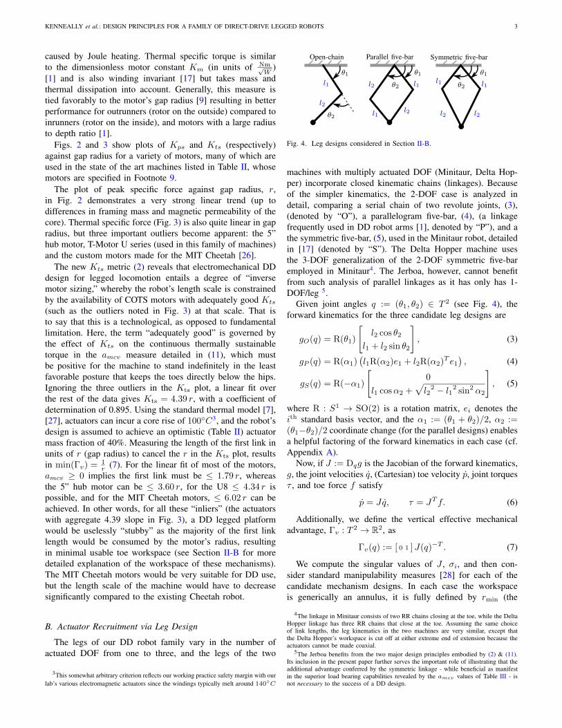
Fig. 4. Leg designs considered in Section II-B.
machines with multiply actuated DOF (Minitaur, Delta Hop-per) incorporate closed kinematic chains (linkages). Becauseof the simpler kinematics, the 2-DOF case is analyzed indetail, comparing a serial chain of two revolute joints, (3),(denoted by “O”), a parallelogram five-bar, (4), (a linkagefrequently used in DD robot arms [1], denoted by “P”), and athe symmetric five-bar, (5), used in the Minitaur robot, detailedin [17] (denoted by “S”). The Delta Hopper machine usesthe 3-DOF generalization of the 2-DOF symmetric five-baremployed in Minitaur4. The Jerboa, however, cannot benefitfrom such analysis of parallel linkages as it has only has 1-DOF/leg 5.
Given joint angles q := (1
,
2
) 2 T
2 (see Fig. 4), theforward kinematics for the three candidate leg designs are
gO(q) = R(1
)
"l
2
cos 2
l
1
+ l
2
sin 2
#, (3)
gP (q) = R(↵1
)l
1
R(↵2
)e1
+ l
2
R(↵2
)T e1
, (4)
gS(q) = R(↵
1
)
"0
l
1
cos↵2
+pl
2
2 l
1
2 sin2 ↵2
#, (5)
where R : S1 ! SO(2) is a rotation matrix, ei denotes thei
th standard basis vector, and the ↵
1
:= (1
+
2
)/2, ↵2
:=(
1
2
)/2 coordinate change (for the parallel designs) enablesa helpful factoring of the forward kinematics in each case (cf.Appendix A).
Now, if J := Dqg is the Jacobian of the forward kinematics,g, the joint velocities q, (Cartesian) toe velocity p, joint torques , and toe force f satisfy
p = Jq, = J
Tf. (6)
Additionally, we define the vertical effective mechanicaladvantage, v : T 2 ! R2, as
v(q) := [ 0 1 ] J(q)T. (7)
We compute the singular values of J , i, and then con-sider standard manipulability measures [28] for each of thecandidate mechanism designs. In each case the workspaceis generically an annulus, it is fully defined by r
min
(the
4The linkage in Minitaur consists of two RR chains closing at the toe, while the DeltaHopper linkage has three RR chains that close at the toe. Assuming the same choiceof link lengths, the leg kinematics in the two machines are very similar, except thatthe Delta Hopper’s workspace is cut off at either extreme end of extension because theactuators cannot be made coaxial.
5The Jerboa benefits from the two major design principles embodied by (2) & (11).Its inclusion in the present paper further serves the important role of illustrating that theadditional advantage conferred by the symmetric linkage - while beneficial as manifestin the superior load bearing capabilities revealed by the amcv values of Table III - isnot necessary to the success of a DD design.
4 IEEE ROBOTICS AND AUTOMATION LETTERS. PREPRINT VERSION. JANUARY, 2016
minimum radius) and r
max
(the maximum radius). In eachof the following subsections, we have fixed a constant r
max
,and plotted a relevant measure over two axes:a) the design space, := r
min
rmax
, where r
min
= |l1
l
2
|,r
max
= l
1
+ l
2
andb) the workspace variable, y representing the radial extension
of the leg.6
1)
min
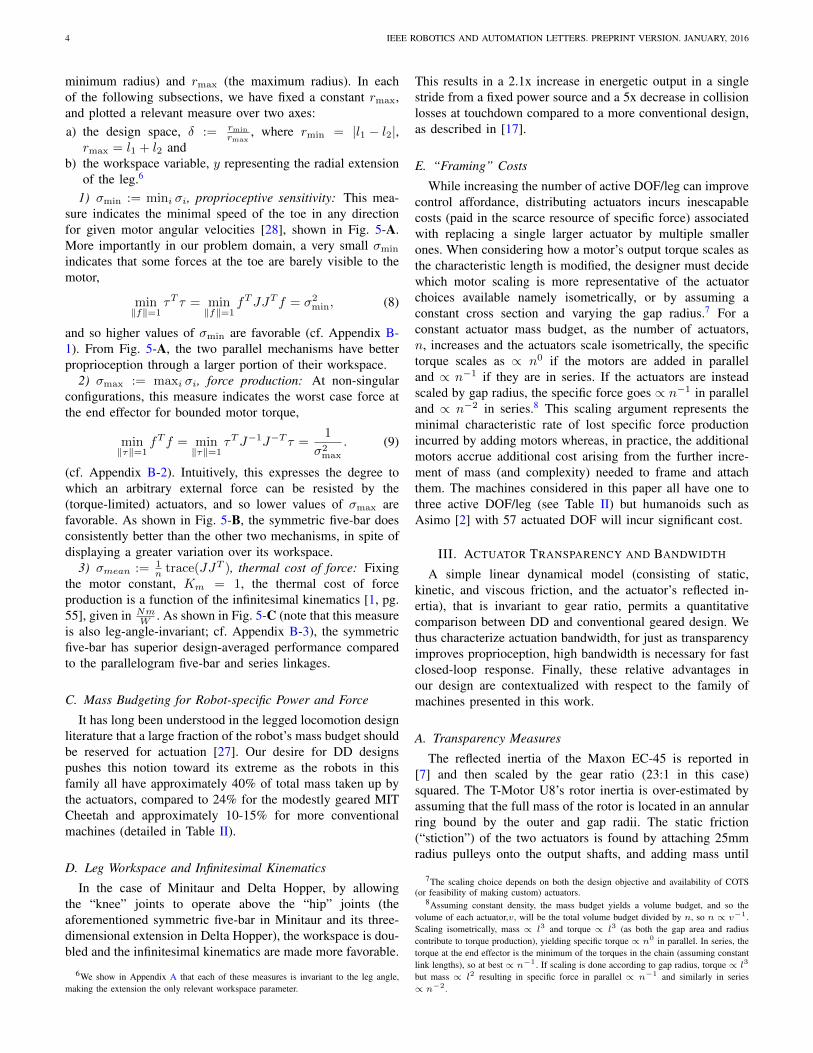
:= mini i, proprioceptive sensitivity: This mea-sure indicates the minimal speed of the toe in any directionfor given motor angular velocities [28], shown in Fig. 5-A.More importantly in our problem domain, a very small
min
indicates that some forces at the toe are barely visible to themotor,
minkfk=1
T = min
kfk=1
f
TJJ
Tf =
2
min
, (8)
and so higher values of
min
are favorable (cf. Appendix B-1). From Fig. 5-A, the two parallel mechanisms have betterproprioception through a larger portion of their workspace.
2)
max
:= maxi i, force production: At non-singularconfigurations, this measure indicates the worst case force atthe end effector for bounded motor torque,
minkk=1
f
Tf = min
kk=1
TJ
1
J
T =
1
2
max
. (9)
(cf. Appendix B-2). Intuitively, this expresses the degree towhich an arbitrary external force can be resisted by the(torque-limited) actuators, and so lower values of
max
arefavorable. As shown in Fig. 5-B, the symmetric five-bar doesconsistently better than the other two mechanisms, in spite ofdisplaying a greater variation over its workspace.
3) mean := 1
n trace(JJT ), thermal cost of force: Fixingthe motor constant, Km = 1, the thermal cost of forceproduction is a function of the infinitesimal kinematics [1, pg.55], given in Nm
W . As shown in Fig. 5-C (note that this measureis also leg-angle-invariant; cf. Appendix B-3), the symmetricfive-bar has superior design-averaged performance comparedto the parallelogram five-bar and series linkages.
C. Mass Budgeting for Robot-specific Power and ForceIt has long been understood in the legged locomotion design
literature that a large fraction of the robot’s mass budget shouldbe reserved for actuation [27]. Our desire for DD designspushes this notion toward its extreme as the robots in thisfamily all have approximately 40% of total mass taken up bythe actuators, compared to 24% for the modestly geared MITCheetah and approximately 10-15% for more conventionalmachines (detailed in Table II).
D. Leg Workspace and Infinitesimal KinematicsIn the case of Minitaur and Delta Hopper, by allowing
the “knee” joints to operate above the “hip” joints (theaforementioned symmetric five-bar in Minitaur and its three-dimensional extension in Delta Hopper), the workspace is dou-bled and the infinitesimal kinematics are made more favorable.
6We show in Appendix A that each of these measures is invariant to the leg angle,making the extension the only relevant workspace parameter.
This results in a 2.1x increase in energetic output in a singlestride from a fixed power source and a 5x decrease in collisionlosses at touchdown compared to a more conventional design,as described in [17].
E. “Framing” CostsWhile increasing the number of active DOF/leg can improve
control affordance, distributing actuators incurs inescapablecosts (paid in the scarce resource of specific force) associatedwith replacing a single larger actuator by multiple smallerones. When considering how a motor’s output torque scales asthe characteristic length is modified, the designer must decidewhich motor scaling is more representative of the actuatorchoices available namely isometrically, or by assuming aconstant cross section and varying the gap radius.7 For aconstant actuator mass budget, as the number of actuators,n, increases and the actuators scale isometrically, the specifictorque scales as / n
0 if the motors are added in paralleland / n
1 if they are in series. If the actuators are insteadscaled by gap radius, the specific force goes / n
1 in paralleland / n
2 in series.8 This scaling argument represents theminimal characteristic rate of lost specific force productionincurred by adding motors whereas, in practice, the additionalmotors accrue additional cost arising from the further incre-ment of mass (and complexity) needed to frame and attachthem. The machines considered in this paper all have one tothree active DOF/leg (see Table II) but humanoids such asAsimo [2] with 57 actuated DOF will incur significant cost.
III. ACTUATOR TRANSPARENCY AND BANDWIDTH
A simple linear dynamical model (consisting of static,kinetic, and viscous friction, and the actuator’s reflected in-ertia), that is invariant to gear ratio, permits a quantitativecomparison between DD and conventional geared design. Wethus characterize actuation bandwidth, for just as transparencyimproves proprioception, high bandwidth is necessary for fastclosed-loop response. Finally, these relative advantages inour design are contextualized with respect to the family ofmachines presented in this work.
A. Transparency MeasuresThe reflected inertia of the Maxon EC-45 is reported in
[7] and then scaled by the gear ratio (23:1 in this case)squared. The T-Motor U8’s rotor inertia is over-estimated byassuming that the full mass of the rotor is located in an annularring bound by the outer and gap radii. The static friction(“stiction”) of the two actuators is found by attaching 25mmradius pulleys onto the output shafts, and adding mass until
7The scaling choice depends on both the design objective and availability of COTS(or feasibility of making custom) actuators.
8Assuming constant density, the mass budget yields a volume budget, and so thevolume of each actuator,v, will be the total volume budget divided by n, so n / v1.Scaling isometrically, mass / l3 and torque / l3 (as both the gap area and radiuscontribute to torque production), yielding specific torque / n0 in parallel. In series, thetorque at the end effector is the minimum of the torques in the chain (assuming constantlink lengths), so at best / n1. If scaling is done according to gap radius, torque / l3
but mass / l2 resulting in specific force in parallel / n1 and similarly in series/ n2.
KENNEALLY et al.: DESIGN PRINCIPLES FOR A FAMILY OF DIRECT-DRIVE LEGGED ROBOTS 5
Open-chainParallel 5barSymmetric 5bar0.00
0.02
0.04
0.06
0.08
A:min
Workspace Average
0.000.050.100.150.200.250.30
Exte
nsio
n
Open-chain (O) Parallel five-bar (P) Symmetric five-bar (S)
Fig. 5. In each of the subfigures (rows) the first column shows the workspace averaged measure of the particular function of singular values, , plottedagainst the ratio of minimal to maximal leg radius, . The remaining three columns provide a more detailed view of the particular as a function of both and leg extension. A: Leg Jacobian minimum singular values (Section II-B1): higher values yield greater proprioceptive sensitivity. B: Leg Jacobian maximumsingular values (Section II-B2): lower values indicate better minimum force production. C: Leg Jacobian mean singular values (Section II-B3): lower valuesindicate smaller thermal cost of producing force. In each figure, the vertical dashed line indicates the linkage used in the Minitaur leg.
there is movement. Using the same pulleys, varying masses areattached and allowed to fall for 2m, accelerating the motors.This time series data is fit to a first-order system and the steadyspeed is extracted in each trial. This experiment is performedat five different steady speeds for each motor (10-200 rad
s forthe U8 and 5-20 rad
s for the EC45) resulting in a strong affinefit (coefficient of determination > 0.995), where the verticalaxis intercept and slope are the kinetic (“Coulomb” or “dry”)and viscous (“Rayleigh” or “damping”) friction coefficients,respectively.
In each of the three measures shown in Table I, the DDactuator (U8) fared significantly better than the conventionalgeared alternative (EC-45, 23:1), representing a 96x decreasein reflected inertia, 3.89x decrease in static friction, 3.83xdecrease in kinetic friction, and 54.6x decrease in viscousdrag. This comes at the price of a 2.5x decrease in continuousand a 5.39x decrease in peak specific torque. We leavethe larger issues of this tradeoff to the existing analysis inthe prior DD robotics literature [1] because we believe thecost/benefit relationships are general to the field whereas weare specifically focused here, simply on the achievability ofDD design for legged locomotion.
B. Reflected Inertia Invariance
If motors are scaled by varying gap radius, r, then torque/ r
2 and inertia / r
3, and so torque/inertia / 1
r . If the motorsare scaled isometrically, inertia goes / r
4, and torque / r
3, soonce again torque/inertia is / 1
r . Considering a gearbox with
TABLE ICOMPARISON OF SPECIFIC CONVENTIONAL AND DD ACTUATORS.
EC45-70W, 23:1 U8
Mass (kg) 0.35 0.25Kv ( rev
V sec
) 0.188 1.67
Continuous Torque (Nm) 2.95 0.855
Peak Torque (Nm) 18.86 3.5
Max Continuous Power @15V (W) 12.18 35.63
Reflected Inertia (kg-m2) 0.0096 0.0001
Static Friction (Nm) 0.218 0.056
Kinetic Friction (Nm) 0.088 0.023
Viscous Friction ( Nmrad/s ) 0.0071 0.00013
Backlash (deg) 0.8 0
gear ratio G, torque goes / G, reflected inertia / G
2, and sotorque/inertia / 1
G . In both cases, to increase torque (eitherby choosing a motor with a larger gap radius, or by increasingthe gear ratio) the price in terms of increased reflected inertiais the same, giving no advantage to minimal gear ratio or evenDD.
C. Actuation BandwidthActuation bandwidth between the two motors of interest
(EC45 23:1, and U8) was explored by connecting the motors toa power supply at 12V, and limited to their thermally sustain-able currents representing a 100C rise in steady state (3.25Aand 9A respectively). The motors were then commanded
6 IEEE ROBOTICS AND AUTOMATION LETTERS. PREPRINT VERSION. JANUARY, 2016
0.5 1 5 10 20
0.1
1
10
50
Frequency (Hz)
Am
plitu
de(r
ev)
T-motor U8Maxon EC-45, 23:1
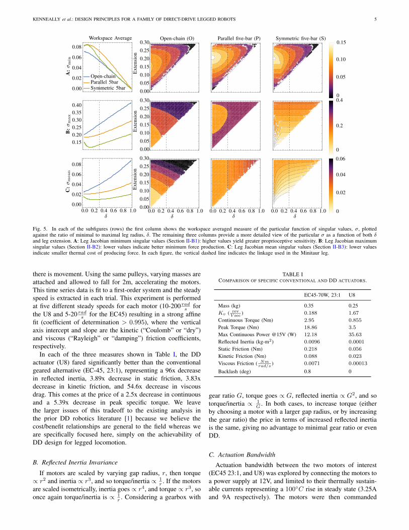
Fig. 6. Bode plot of amplitude response (in revolutions) to sinusoidal voltageinput at various frequencies.
TABLE IIPHYSICAL PROPERTIES OF THE MACHINES OF INTEREST (II-C).
open-loop sinusoidal voltages at various frequencies, and theamplitude of the output shaft of the motor (in revolutions)was recorded. The U8s performed significantly better at thisbandwidth measure, rotating on average 17.4x more than thegeared EC45’s, as shown in Fig. 6.
D. Relevance to Behaviors
For the 2–5 kg machines in this family, the duration ofstance phase is on the order of 0.1 seconds, corresponding(roughly) to a spring-mass time constant of > 5 Hz for eachstance leg. This illustrates the importance of having goodactuation performance at the time scales depicted in Figure 6.
IV. IMPLEMENTATION AND PERFORMANCE
The basic motor control electrical subsystem of the DDfamily is described in [5, Section V-A.3], stemming fromwork reported in [4]. Of additional relevance to this paperis the closed-loop control architecture, which, building onthe brushless servo approach of [29] is implemented using
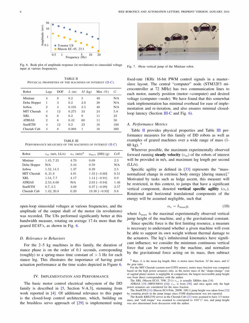
Fig. 7. 48cm vertical jump of the Minitaur robot.
fixed-rate 1KHz 16-bit PWM control signals in a master–slave layout. The central “computer” node (STM32F3 mi-crocontroller at 72 MHz) has two communication lines toeach motor, namely position (motor!computer) and desiredvoltage (computer!node). We have found that this somewhatstark implementation has minimal overhead for ease of imple-mentation and re-iteration, and also ensures minimal closed-loop latency (Section III-C and Fig. 6).
A. Performance MetricsTable II provides physical properties and Table III per-
formance measures for this family of DD robots as well asexamples of geared machines over a wide range of mass (1-60 kg). 9
Wherever possible, the maximum experimentally observedforward running steady velocity (v
ss
) of the robots of interestwill be provided in m/s, and maximum leg length per second(LL/s).
Specific agility as defined in [33] represents the “mass-normalized change in extrinsic body energy [during stance].”Motivated by tasks such as ledge ascent, this measure willbe restricted, in this context, to jumps that have a significantvertical component, denoted vertical specific agility (↵v).Rotational and horizontal translational components of theenergy will be assumed negligible, such that
↵v = h
max
g, (10)
where h
max
is the maximal experimentally observed verticaljump height of the machine, and g the gravitational constant.
Since specific force is the first limiting resource, a measureis necessary to understand whether a given machine will evenbe able to support its own weight without thermal damage tothe actuators. The leg’s infinitesimal kinematics have signifi-cant influence; we consider the minimum continuous verticalforce that can be exerted by the machine, and normalizeby the gravitational force acting on its mass, then subtract
9 Here, L is the mean leg length, Mot. is motor mass fraction, M the mass, and Gthe gear ratio.
For the MIT Cheetah (custom non-COTS motors), motor mass fraction was computedbased on the high power actuators only, as the motor mass of the “shape-change” (outof sagittal plane) motors is negligible in comparison, the largest recoverable jump heightwas from direct correspondence with the author.
The XRL (Maxon EC45, 70W, 23:1) vss is actually XRHex data [18].ATRIAS [19] (MF0150010 [24]) vss is from [30], and once again only the high
power actuators are considered for the mass fraction.The StarlETH [31] (Maxon EC4-Pole, 200W, 100:1) jump height was taken from [32]
by counting pixels in the jump image since COM displacement was not reported.The Kondo KRS2350 servos in the Cheetah Cub [21] were assumed to have 1/3 motor
mass, and “stall torque” was assumed to correspond to 100
C rise, and jump heightwas also determined from discussion with the author.
KENNEALLY et al.: DESIGN PRINCIPLES FOR A FAMILY OF DIRECT-DRIVE LEGGED ROBOTS 7
one, yielding an estimate of the minimal continuous vertical
acceleration (amcv
):
a
mcv
:=cnl
mg
minq
v(q)
1 (11)
whereby we assume that all legs have sufficient workspace forthe links to be parallel. c denotes the thermally sustainablecontinuous torque (assumed to be a 100C rise), and nl thenumber of legs that can push vertically. This dimensionlessnumber will indicate if the machine will be able to supportits own weight at any point in the leg’s workspace ( 0), andrepresents the instantaneous vertical acceleration of the bodyin units of gravitational constant. For comparisons with othermachines, the measure is listed both as designed and also asif the machine’s gearbox were removed.
The cost of transport (specific resistance [34], [35]) iscomputed using mean voltage (V ) and current (i):
CoT :=V i
Mgv
ss
(12)
B. Performance of the DD machinesThe family of DD machines in this paper performs sim-
ilarly or better in conventional measures compared to moreestablished, geared, machines. The Minitaur robot has forwardrunning speed (vss) of 1.45m
s for a bound, and 0.8ms for a
pronk, competitive for machines around its length scale, andits vertical jump height (represented by ↵v , and shown inFig. 7) is the second best of all the machines considered. Thespecific resistance of the DD robots is no worse than that ofother machines of a similar scale (StarlETH and Cheetah Cub),though the larger machines perform better (as expected). Ourmachines have proven to be quite robust both mechanicallyand thermally and have each been run for tens of hours asthe gaits were developed. We believe that the true benefits ofour DD machines will be realized in tasks that fully exploitthe increased proprioception, such as rapid transitions betweensubstrates or locomotion modalities, a topic we leave to futurework.
V. CONCLUSION
This paper outlines a design methodology that brings thewell known benefits of DD robotics to legged locomotion.These benefits include significant improvements (3.8x–96x)in the constituent components (reflected inertia, and static,kinetic, and viscous friction) of a simple actuator “trans-parency” model, as well as a 17.4x improvement in rotationalbandwidth as compared to a representative geared motor(Maxon EC45 flat, 23:1). The family of machines built withthese actuators in accordance with the design principles listedabove has proven very competitive with state of the art leggedmachines, according to a variety of metrics. The diversity ofmorphologies and similarly competitive running and leapinggaits exhibited by the family of machines we describe suggeststhat DD legged locomotion may be more readily achievablethan its very sparse literature hitherto might suggest.
Work currently in progress addresses a number of importantquestions concerning the role of form and function that lies
beyond the scope of the present design-focused paper. Carefulstudy will be required to tease out the relative contributionsto overall energetic efficiency due to DD–both advantages anddisadvantages–as distinct from the control policies they enable.In addition to the convincing and tunable compliance thatDD affords, these machines do not preclude integration ofpassive, purely mechanical, compliance elements. From themorphological perspective, the analysis of framing cost, inSection II-E suggests an approach to actuator granularity thatmight help rationalize decisions as to how many appendages ofa number of DOF a robot might requires to achieve a specifieddomain of tasks.
We believe we have merely scratched the surface in extract-ing the benefits of “transparency” that DD actuation offerslegged robotics. The high sensorimotor bandwidth enjoyed bythese machines greatly facilitates simple reactive strategies,affording, for example, reliable observer-free proprioceptivetouchdown detection (cf. [36]). In turn, bringing such highsensing and control authority to bear upon platforms whosedynamics are so well described by simple hybrid Lagrangianmechanics [22] facilitates the application and reuse of simple,robust behavioral “modules” whose parallel [37] and sequen-tial [38] compositions can now be extended across multiplebodies as well as flexibly recombined within a single one.Work in progress further exploits these machines’ ability to“feel” their environment in bringing the perspective of “self-manipulation” [22] to bear on legged mobility, especially asit relates to transitional behavior.
VI. ACKNOWLEDGEMENTS
This work was supported by US Army Research Laboratoryunder Cooperative Agreement Number W911NF-10-2-0016and National Science and Engineering Research Council ofCanada 352093. The authors would also like to thank JeffDuperret for the Bode plot code.
APPENDIX
A. Invariance of Leg Design Measures to Leg AngleFor each of the leg designs, there is a linear change of
coordinates L : T 2 ! T
2 from the original joint angles suchthat if ↵ = Lq, then ↵
1
is the “leg angle,” i.e.
g(q) = eg(Lq), eg(↵) = R(↵1
)h(↵2
). (13)
For the serial design (3), LS
= I , and for each of the paralleldesigns (4)–(5), L
P
:= 1
2
1 1
1 1
.
Proposition 1. The singular values of the Jacobian of (13),Dg, are invariant to the leg angle, ↵
1
.
Proof. At first, we show that if L = I , the proposition holds:Using the chain rule on (13),
Dg = SRheT1
+RDh, (14)
where we drop the dependencies R(↵1
), h(↵2
) and Dh(↵2
)for brevity, S :=
0 1
1 0
, and e
1
:= [ 10
]. Now, multiplying andsimplifying (14),
Dg
TDg = Dh
TDh+ e
1
h
The
1
+Dh
TShe
T1
+ e
1
h
TS
TDh,
8 IEEE ROBOTICS AND AUTOMATION LETTERS. PREPRINT VERSION. JANUARY, 2016
and observe that all dependence on ↵
1
(in the form of R in(14)) disappears. Thus, Dg
TDg is invariant to ↵
1
.Lastly, since DL = L is constant, and
Dg
TDg = L
TDegTDegL, (15)
the linear coordinate change L does not affect this proposition,and the argument above for L = I carries over directly.
B. Relation of Measures to Jacobian Singular ValuesLet the (ordered) singular values of the square matrix J be
max
,
min
. Observe that1) The expression on the left hand side of (8) is the Rayleigh
quotient for the matrix JJ
T , which is minimized by itssmallest eigenvalue [39]. Additionally, J
T and J havethe same singular values, and so any measure dependingon the singular values of J or of J
T is invariant to legangle (Appendix A).
2) Since the eigenvalues of (JTJ)1 are the reciprocals of
eigenvalues of J
TJ , the singular values of J appear in
the denominator of (9).3) Since trace(JJT ) = trace(JT
J), the Asada metric ofII-B3 is also independent of leg angle.
REFERENCES
[1] H. Asada and K. Youcef-Toumi, Direct-drive robots: theory and prac-tice. MIT press, 1987.
[2] Y. Sakagami, R. Watanabe, C. Aoyama, S. Matsunaga, N. Higaki, andK. Fujimura, “The intelligent asimo: System overview and integration,”in Intelligent Robots and Systems, 2002. IEEE/RSJ International Con-ference on, vol. 3. IEEE, 2002, pp. 2478–2483.
[3] G. A. Pratt and M. M. Williamson, “Series elastic actuators,” IEEEInternational Conference on Intelligent Robots and Systems, vol. 1, pp.399–406, 1995.
[4] G. Kenneally, A. De, and D. E. Koditschek, “Design principles for afamily of direct-drive legged robots,” in Robotics: Science and Systems,Workshop, 2015. [Online]. Available: kodlab.seas.upenn.edu/uploads/Main/gake dddesign.pdf
[5] A. De and D. E. Koditschek, “The penn jerboa: A platform for exploringparallel composition of templates,” arXiv preprint arXiv:1502.05347,2015.
[6] J. W. Hurst, “The role and implementation of compliance in leggedlocomotion,” Ph.D. dissertation, Robotics Institute, Carnegie MellonUniversity, Pittsburgh, PA, August 2008.
[8] A. Wang and S. Kim, “Directional efficiency in geared transmissions:Characterization of backdrivability towards improved proprioceptivecontrol,” in Robotics and Automation (ICRA), 2015 IEEE InternationalConference on, may 2015, pp. 1055–1062.
[9] S. Seok, A. Wang, D. Otten, and S. Kim, “Actuator design for high forceproprioceptive control in fast legged locomotion,” IEEE InternationalConference on Intelligent Robots and Systems, pp. 1970–1975, 2012.
[10] N. Hogan, “Impedance control: An approach to manipulation: part1 - theory.” Journal of Dynamic Systems, Measurement and Control,Transactions of the ASME, vol. 107, no. 1, pp. 1–7, 1985.
[11] M. H. Raibert and Others, Legged robots that balance. MIT pressCambridge, MA, 1986, vol. 3.
[12] D. E. Koditschek, “Some applications of natural motion control,” Jour-nal of Dynamic Systems, Measurement, and Control, vol. 113, p. 552,1991.
[13] C. Loughlin, A. Albu-Schaffer, S. Haddadin, C. Ott, A. Stemmer,T. Wimbock, and G. Hirzinger, “The dlr lightweight robot: design andcontrol concepts for robots in human environments,” Industrial Robot:an international journal, vol. 34, no. 5, pp. 376–385, 2007.
[14] A. J. Spence, S. Revzen, J. Seipel, C. Mullens, and R. J. Full, “Insectsrunning on elastic surfaces,” The Journal of experimental biology, vol.213, no. 11, pp. 1907–1920, 2010.
[15] R. S. Wallace, “Miniature direct drive rotary actuators ii: Eye, fingerand leg,” Proceedings - IEEE International Conference on Robotics andAutomation, no. pt 2, pp. 1496–1501, 1994.
[16] B. Na, H. Choi, and K. Kong, “Design of a direct-driven linearactuator for a high-speed quadruped robot, cheetaroid-i,” IEEE/ASMETransactions on Mechatronics, vol. 20, no. 2, pp. 924–933, 2015.
[17] G. Kenneally and D. E. Koditschek, “Leg Design for Energy Manage-ment in an Electromechanical Robot,” IEEE/RSJ International Confer-ence on Intelligent Robots and Systems (In Press), 2015.
[18] K. C. Galloway, G. C. Haynes, B. D. Ilhan, A. M. Johnson, R. Knopf,G. Lynch, B. Plotnick, M. White, and D. E. Koditschek, “X-rhex: Ahighly mobile hexapedal robot for sensorimotor tasks,” University ofPennsylvania, Tech. Rep., 2010.
[19] J. Grimes and J. Hurst, “The design of atrias 1.0 a unique monopod,hopping robot,” Adaptive Mobile Robotics - Proceedings of the 15thInternational Conference on Climbing and Walking Robots and theSupport Technologies for Mobile Machines, CLAWAR 2012, pp. 548–554, 2012.
[20] M. Hutter, C. Remy, M. Hoepflinger, and R. Siegwart, “Efficient andversatile locomotion with highly compliant legs,” IEEE/ASME Transac-tions on Mechatronics, vol. 18, no. 2, pp. 449–458, 2013.
[21] A. Sprowitz, A. Tuleu, M. Vespignani, M. Ajallooeian, E. Badri, andA. J. Ijspeert, “Towards dynamic trot gait locomotion: Design, control,and experiments with Cheetah-cub, a compliant quadruped robot,” TheInternational Journal of Robotics Research, vol. 32, pp. 932–950, 2013.
[22] A. Johnson and D. Koditschek, “Legged self-manipulation,” IEEE Ac-cess, vol. 1, pp. 310–334, 2013.
[23] T-motor u8 datasheet. [Online]. Available: www.rctigermotor.com/[24] Allied motion datasheet. [Online]. Available: www.alliedmotion.com/[25] Uu motor datasheet. [Online]. Available: www.uumotor.com/[26] S. Seok, A. Wang, M. Chuah, D. Otten, J. Lang, and S. Kim, “Design
principles for highly efficient quadrupeds and implementation on themit cheetah robot,” Proceedings - IEEE International Conference onRobotics and Automation, pp. 3307–3312, 2013.
[27] H. Rad, P. Gregori, and M. Buehler, “Design, modeling and control ofa hopping robot,” International Conference on Intelligent Robots andSystems, pp. 1778–1785, 1993.
[28] R. M. Murray, Z. Li, S. S. Sastry, and S. S. Sastry, A mathematicalintroduction to robotic manipulation. CRC press, 1994.
[29] M. Piccoli and M. Yim, “Anticogging: Torque ripple suppression,modeling, and parameter selection,” International Journal of RoboticsResearch, vol. 35, no. 1-3, pp. 148–160, 2016.
[31] M. Hutter, C. Gehring, M. Bloesch, M. Hoepflinger, C. Remy, andR. Siegwart, “Starleth: A compliant quadrupedal robot for fast, efficient,and versatile locomotion,” Adaptive Mobile Robotics - Proceedings ofthe 15th International Conference on Climbing and Walking Robots andthe Support Technologies for Mobile Machines, CLAWAR 2012, pp. 483–490, 2012.
[32] C. Gehring, S. Coros, M. Hutter, and R. Siegwart, “An optimizationapproach to controlling jump maneuvers for a quadruped robot,” inConference on Dynamic Walking, 2015.
[33] J. M. Duperret, G. D. Kenneally, J. L. Pusey, and D. E. Koditschek,“Towards a comparative measure of legged agility,” in InternationalSymposium on Experimental Robotics, June 2014, pp. 3–16.
[34] M. Ahmadi and M. Buehler, “The arl monopod ii running robot: Controland energetics,” in Robotics and Automation, 1999. Proceedings. 1999IEEE International Conference on, vol. 3. IEEE, 1999, pp. 1689–1694.
[35] G. Gabrielli and T. von Karman, “What price speed?” in MechanicalEngineering, vol. 72, 1950, pp. 775–781.
[36] A. Johnson, G. Haynes, and D. Koditschek, “Disturbance detec-tion, identification, and recovery by gait transition in legged robots,”IEEE/RSJ 2010 International Conference on Intelligent Robots andSystems, IROS 2010 - Conference Proceedings, pp. 5347–5353, 2010.
[37] A. De and D. Koditschek, “Parallel composition of templates for tail-energized planar hopping,” Proceedings - IEEE International Conferenceon Robotics and Automation, pp. 4562–4569, 2015.
[38] A. L. Brill, A. De, A. M. Johnson, and D. E. Koditschek, “Tail-assistedrigid and compliant legged leaping,” IEEE/RSJ International Conferenceon Intelligent Robots and Systems, p. (in press).
[39] R. Horn and C. Johnson, Matrix Analysis. Cambridge University Press,1990.