KLM Technology Group Practical Engineering Guidelines for Processing Plant Solutions SOLUTIONS, STANDARDS AND SOFTWARE www.klmtechgroup.com Page : 1 of 90 Rev: 01 Rev 1 April 2017 KLM Technology Group #03-12 Block Aronia, Jalan Sri Perkasa 2 Taman Tampoi Utama 81200 Johor Bahru Kolmetz Handbook of Process Equipment Design REFINERY CATALYTIC REFORMING DESIGN, SIZING AND TROUBLESHOOTING (ENGINEERING DESIGN GUIDELINE) Co Authors Rev 1 Apriliana Editor / Author Karl Kolmetz KLM Technology Group has developed; 1) Process Engineering Equipment Design Guidelines, 2) Equipment Design Software, 3) Project Engineering Standards and Specifications, 4) Unit Operations Manuals and 5) Petrochemical Manufacturing Reports. Each has many hours of engineering development. KLM Technology Group believes that if you have a design, consulting, or troubleshooting project you should consider our senior consultants. KLM is providing the introduction to this guideline for free on the internet. Please go to our website to order the complete document. www.klmtechgroup.com
Transcript
KLM Technology
Group
Practical Engineering Guidelines for Processing
Plant Solutions
SOLUTIONS, STANDARDS AND SOFTWARE
www.klmtechgroup.com
Page : 1 of 90
Rev: 01
Rev 1 April 2017
KLM Technology Group #03-12 Block Aronia, Jalan Sri Perkasa 2 Taman Tampoi Utama 81200 Johor Bahru
Kolmetz Handbook
of Process Equipment Design
REFINERY CATALYTIC REFORMING DESIGN, SIZING
AND TROUBLESHOOTING
(ENGINEERING DESIGN GUIDELINE)
Co Authors Rev 1 Apriliana
Editor / Author Karl Kolmetz
KLM Technology Group has developed; 1) Process Engineering Equipment Design Guidelines, 2) Equipment Design Software, 3) Project Engineering Standards and Specifications, 4) Unit Operations Manuals and 5) Petrochemical Manufacturing Reports. Each has many hours of engineering development. KLM Technology Group believes that if you have a design, consulting, or troubleshooting project you should consider our senior consultants. KLM is providing the introduction to this guideline for free on the internet. Please go to our website to order the complete document.
www.klmtechgroup.com
KLM Technology Group
Practical Engineering
Guidelines for Processing Plant Solutions
Kolmetz Handbook of Process Equipment Design
REFINERY CATALYTIC REFORMING DESIGN, SIZING
AND TROUBLESHOOTING
(ENGINEERING DESIGN GUIDELINES)
Page 2 of 90
Rev: 01
April 2017
These design guidelines are believed to be as accurate as possible, but are very general and not for specific design cases. They were designed for engineers to do preliminary designs and process specification sheets. The final design must always be guaranteed for the service selected by the manufacturing vendor, but these guidelines will greatly reduce the amount of up front engineering hours that are required to develop the final design. The guidelines are a training tool for young engineers or a resource for engineers with experience. This document is entrusted to the recipient personally, but the copyright remains with us. It must not be copied, reproduced or in any way communicated or made accessible to third parties without our written consent.
TABLE OF CONTENT INTRODUCTION 5 Scope 5 General Design Consideration 9 DEFINITION 23 NOMENCLATURE 25 THEORY OF THE DESIGN 26
Catalytic Reforming Techniques 26 CCR Platforming 35 Common Problems 53 Reactor 54 Catalysts 56 Process Variables 64 Troubleshooting 71
KLM Technology Group
Practical Engineering
Guidelines for Processing Plant Solutions
Kolmetz Handbook of Process Equipment Design
REFINERY CATALYTIC REFORMING DESIGN, SIZING
AND TROUBLESHOOTING
(ENGINEERING DESIGN GUIDELINES)
Page 3 of 90
Rev: 01
April 2017
These design guidelines are believed to be as accurate as possible, but are very general and not for specific design cases. They were designed for engineers to do preliminary designs and process specification sheets. The final design must always be guaranteed for the service selected by the manufacturing vendor, but these guidelines will greatly reduce the amount of up front engineering hours that are required to develop the final design. The guidelines are a training tool for young engineers or a resource for engineers with experience. This document is entrusted to the recipient personally, but the copyright remains with us. It must not be copied, reproduced or in any way communicated or made accessible to third parties without our written consent.
APPLICATION Application 1: Material Balance 79 Application 2: Reactor Design 81 Application 3: Furnace Design 83 REFEREENCE 84 LIST OF TABLE Table 1: Various Catalytic Reforming Processes 5 Table 2: The composition of two typical feeds 7 Table 3: Examples of research and motor octane of pure hydrocarbons 9 Table 4: Catalytic reaction with catalyst chemistry 18 Table 5: The difference of Reforming processes 34 Table 6: Platforming catalysts CCR operation 41 Table 7: Relative severities of CCR versus SR platforming units 51 Table 8: Yield comparison of CCR versus SR platforming units 52 Table 9: Economic summary 53 Table 10: Optional response for bad performance 71 Table 11: Operational response for water, sulphur and nitrogen upset 74
KLM Technology Group
Practical Engineering
Guidelines for Processing Plant Solutions
Kolmetz Handbook of Process Equipment Design
REFINERY CATALYTIC REFORMING DESIGN, SIZING
AND TROUBLESHOOTING
(ENGINEERING DESIGN GUIDELINES)
Page 4 of 90
Rev: 01
April 2017
These design guidelines are believed to be as accurate as possible, but are very general and not for specific design cases. They were designed for engineers to do preliminary designs and process specification sheets. The final design must always be guaranteed for the service selected by the manufacturing vendor, but these guidelines will greatly reduce the amount of up front engineering hours that are required to develop the final design. The guidelines are a training tool for young engineers or a resource for engineers with experience. This document is entrusted to the recipient personally, but the copyright remains with us. It must not be copied, reproduced or in any way communicated or made accessible to third parties without our written consent.
LIST OF FIGURE Figure 1: ASTM D-86 distillation curve for naphtha 7 Figure 2: Sulfur types 8 Figure 3: the decreases octane in some hydrocarbon 10 Figure 4: Generalized catalytic reforming reaction scheme 12 Figure5: Total changes to produce iso-Paraffins and Aromatics 18 Figure 6: Catalytic reforming process flow 20 Figure 7: Semi - regenerative unit 29 Figure 8. Semi-regenerative reforming process 30 Figure 9: Semi - regenerative reactor (Spherical Design) 31 Figure 10: Semi - regenerative reactor 31 Figure 11: Continuous - regenerative unit 33 Figure 12: Basic Platforming Process Flow 35 Figure 13: CCR Platforming process 39 Figure 14: Catalytic reforming reactions 40 Figure 15: Continuous Platforming Stacked Radial Flow Reactors 42 Figure 16: CCR Platforming Reactor-Intermediate Reactor Cone Area 43 Figure 17: Platforming Unit Heater Radiant Section 45
KLM Technology Group
Practical Engineering
Guidelines for Processing Plant Solutions
Kolmetz Handbook of Process Equipment Design
REFINERY CATALYTIC REFORMING DESIGN, SIZING
AND TROUBLESHOOTING
(ENGINEERING DESIGN GUIDELINES)
Page 5 of 90
Rev: 01
April 2017
These design guidelines are believed to be as accurate as possible, but are very general and not for specific design cases. They were designed for engineers to do preliminary designs and process specification sheets. The final design must always be guaranteed for the service selected by the manufacturing vendor, but these guidelines will greatly reduce the amount of up front engineering hours that are required to develop the final design. The guidelines are a training tool for young engineers or a resource for engineers with experience. This document is entrusted to the recipient personally, but the copyright remains with us. It must not be copied, reproduced or in any way communicated or made accessible to third parties without our written consent.
Figure 18: Vertical Combined Feed Exchanger 46 Figure 19: Recycle Gas Compressor 5 Stage Centrifugal Compressor 47 Figure 20: Separator 49 Figure 21: Debutanizer Overhead Receiver (with Water Boot) 50 Figure 22: Furnace (F1, F2, F3) and reactor (R1, R2, R3) layout. 55 Figure 23: Moving bed reactor 56 Figure 24: Catalyst Components Representation 58 Figure 25: Catalyst Preparation 25 Figure 26: Catalyst regeneration section 64 Figure 27: Influence of P and the feed on C5+ yield 66 Figure 28: Variation in octane number versus TSOR 68 Figure 29: Water-chloride balance 74
KLM Technology Group
Practical Engineering
Guidelines for Processing Plant Solutions
Kolmetz Handbook of Process Equipment Design
REFINERY CATALYTIC REFORMING DESIGN, SIZING
AND TROUBLESHOOTING
(ENGINEERING DESIGN GUIDELINES)
Page 6 of 90
Rev: 01
April 2017
These design guidelines are believed to be as accurate as possible, but are very general and not for specific design cases. They were designed for engineers to do preliminary designs and process specification sheets. The final design must always be guaranteed for the service selected by the manufacturing vendor, but these guidelines will greatly reduce the amount of up front engineering hours that are required to develop the final design. The guidelines are a training tool for young engineers or a resource for engineers with experience. This document is entrusted to the recipient personally, but the copyright remains with us. It must not be copied, reproduced or in any way communicated or made accessible to third parties without our written consent.
INTRODUCTION Scope This guideline provides knowledge on how to design a refining catalytic reforming unit. This design guideline can assist to understand the basic design of catalytic reforming with suitable size, material and heat of combustion. Catalytic reforming is a major conversion process in a petroleum refinery and petrochemical industries. The problem of low octane ratings of naphtha is solved by increasing the contents of isomers and aromatics in its composition. In the catalytic reforming unit of a refinery, the objective is to convert lower octane value naphtha into higher octane reformate that can be used for gasoline blending. The function of the reformer is to efficiently convert paraffins and naphthenes to aromatics with as little ring opening or cracking as possible. Catalytic reforming is a process whereby light petroleum distillates (naphtha) are contacted with a platinum-containing catalyst at elevated temperatures and hydrogen. Reforming involves some reactions such as Isomerization, Dehydrogenation, and Dehydrocyclization which convert the low octane number components in naphtha into very high octane number components, consequently enhancing the antiknock quality of gasoline. Catalytic reforming processes are commonly classified into three types based on the regeneration systems of the catalyst, namely (i) semi-regenerative catalytic reformer process, (ii) cyclic regenerative catalytic reformer process and (iii) continuous catalytic regeneration reformer process. The mechanism for the regeneration steps could be classified into fixed-bed catalyst system; fixed-bed catalyst combined a swing reactor and a moving bed catalyst with special regenerator The theory section explains the selection of the catalytic reforming type, calculation of sizing, trouble shooting, catalyst, and process variable that effect in catalytic reforming. The application of the catalytic reforming theory with the examples assists the user to study the catalytic reforming concepts and be prepared to perform the actual design of the catalytic reforming.
KLM Technology Group
Practical Engineering
Guidelines for Processing Plant Solutions
Kolmetz Handbook of Process Equipment Design
REFINERY CATALYTIC REFORMING DESIGN, SIZING
AND TROUBLESHOOTING
(ENGINEERING DESIGN GUIDELINES)
Page 7 of 90
Rev: 01
April 2017
These design guidelines are believed to be as accurate as possible, but are very general and not for specific design cases. They were designed for engineers to do preliminary designs and process specification sheets. The final design must always be guaranteed for the service selected by the manufacturing vendor, but these guidelines will greatly reduce the amount of up front engineering hours that are required to develop the final design. The guidelines are a training tool for young engineers or a resource for engineers with experience. This document is entrusted to the recipient personally, but the copyright remains with us. It must not be copied, reproduced or in any way communicated or made accessible to third parties without our written consent.
General Design Consideration Catalytic reforming is a major conversion process in petroleum refinery and petrochemical industries. Catalytic reforming is a process whereby light petroleum distillates (naphtha) are contacted with a platinum-containing catalyst at elevated temperatures and hydrogen pressures ranging from 345 to 3,450 kPa (50–500 psig) for the purpose of raising the octane number of the hydrocarbon feed stream. The low octane, paraffin-rich naphtha feed is converted to a high-octane liquid product that is rich in aromatic compounds. catalytic reforming produces reformate with octane numbers of the order of 90 to 95. Hydrogen and other light hydrocarbons are also produced as reaction by-products. In addition to the use of reformate as a blending component of motor fuels, it is also a primary source of aromatics used in the petrochemical industry. The first catalytic reforming units were designed as semi regenerative (SR), or fixed-bed units, using Pt/alumina catalysts. Semi regenerative reforming units are periodically shut down for catalyst regeneration. This involves burning off coke and reconditioning the catalyst’s active metals. To minimize catalyst deactivation, these units were operated at high pressures in the range of 2,760 to 3,450 kPa (400–500 psig). High hydrogen pressure decreases coking and deactivation rates. Catalytic reforming processes were improved by introducing bimetallic catalysts. These catalysts allowed lower pressure, higher severity operation: ∼1,380–2,070 kPa (200–300 psig), at 95–98 octane with typical cycle lengths of one year. Cyclic reforming was developed to allow operation at increased severity. Cyclic reforming still employs fixed-bed reforming, but each reactor in a series of reactors can be removed from the process flow, regenerated, and put back into service without shutting down the unit and losing production. With cyclic reforming, reactor pressures are approximately 200 psig, producing reformates with octanes near 100. Catalytic reforming is conducted in the presence of hydrogen over hydrogenation-dehydrogenation catalysts, which may be supported on alumina or silica–alumina. Depending on the catalyst, a definite sequence of reactions takes place, involving structural changes in the charge stock. The catalytic reforming process was commercially nonexistent in the United States before 1940. The process is really a process of the 1950s and showed phenomenal growth in the 1953–1959 period. As a result, thermal reforming is now somewhat obsolete.
KLM Technology Group
Practical Engineering
Guidelines for Processing Plant Solutions
Kolmetz Handbook of Process Equipment Design
REFINERY CATALYTIC REFORMING DESIGN, SIZING
AND TROUBLESHOOTING
(ENGINEERING DESIGN GUIDELINES)
Page 8 of 90
Rev: 01
April 2017
These design guidelines are believed to be as accurate as possible, but are very general and not for specific design cases. They were designed for engineers to do preliminary designs and process specification sheets. The final design must always be guaranteed for the service selected by the manufacturing vendor, but these guidelines will greatly reduce the amount of up front engineering hours that are required to develop the final design. The guidelines are a training tool for young engineers or a resource for engineers with experience. This document is entrusted to the recipient personally, but the copyright remains with us. It must not be copied, reproduced or in any way communicated or made accessible to third parties without our written consent.
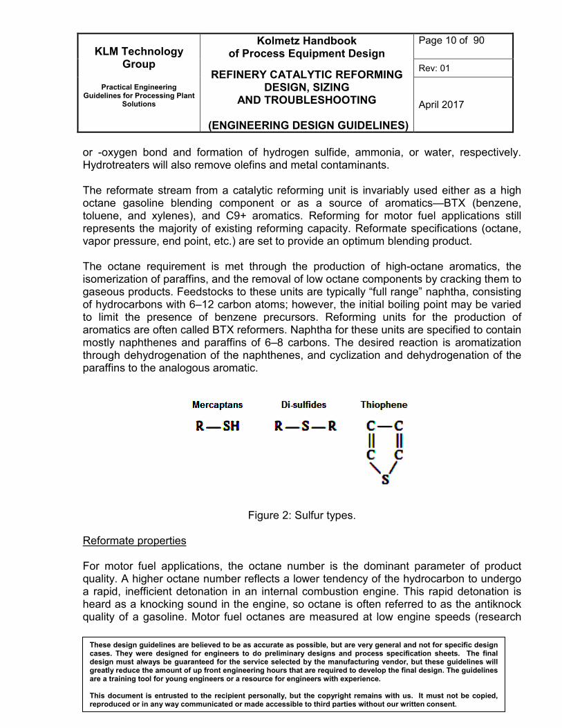
Feedstocks The yield of gasoline of a given octane number and at given operating conditions depends on the hydrocarbon types in the feed. Naphtha feedstocks to reformers typically contain paraffins, naphthenes, and aromatics with 6–12 carbon atoms. In the majority of cases the feed may be a straight-run naphtha, but other byproduct low-octane naphtha (e.g., coker naphtha) can be processed after treatment to remove olefins and other contaminants. Hydrocarbon naphtha that contains substantial quantities of naphthenes is also a suitable feed. high-naphthene stocks, which readily give aromatic gasoline, are the easiest to reform and give the highest gasoline yields. Most feed naphtha have to be hydrotreated to remove metals, olefins, sulfur, and nitrogen, prior to being fed to a reforming unit. A typical straight run naphtha from crude distillation may have a boiling range of 150–400◦F (65–200◦C). In addition to naphtha from crude distillation, naphtha can be derived from a variety of other processes that crack heavier hydrocarbons to hydrocarbons in the naphtha range. Cracked feedstocks may be derived from catalytic cracking, hydrocracking, cokers, thermal cracking, as well as visbreaking, fluid catalytic cracking, and synthetic naphtha obtained, for example, from a Fischer–Tropsch process. Light paraffinic naphtha are more difficult to reform than heavier naphthenic hydrocarbons. Distillation values for the initial boiling point, the mid-point at which 50% of the naphtha is distilled over, and the end point are often used to characterize a naphtha (Figure 1). Paraffinic stocks, however, which depend on the more difficult isomerization, dehydrocyclization, and hydrocracking reactions, require more severe conditions and give lower gasoline yields than the naphthenic stocks. The end point of the feed is usually limited to about 190 °C (375 °F), partially because of increased coke deposition on the catalyst as the end point during processing at about 158 °C (278 °F). Limiting the feed end point avoids re-distillation of the product to meet the gasoline end-point specification of 205 °C (400 °F), maximum.
KLM Technology Group
Practical Engineering
Guidelines for Processing Plant Solutions
Kolmetz Handbook of Process Equipment Design
REFINERY CATALYTIC REFORMING DESIGN, SIZING
AND TROUBLESHOOTING
(ENGINEERING DESIGN GUIDELINES)
Page 9 of 90
Rev: 01
April 2017
These design guidelines are believed to be as accurate as possible, but are very general and not for specific design cases. They were designed for engineers to do preliminary designs and process specification sheets. The final design must always be guaranteed for the service selected by the manufacturing vendor, but these guidelines will greatly reduce the amount of up front engineering hours that are required to develop the final design. The guidelines are a training tool for young engineers or a resource for engineers with experience. This document is entrusted to the recipient personally, but the copyright remains with us. It must not be copied, reproduced or in any way communicated or made accessible to third parties without our written consent.
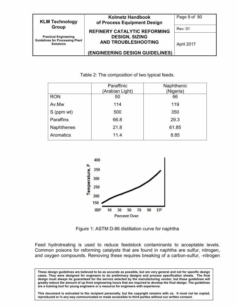
Table 2: The composition of two typical feeds.
Paraffinic (Arabian Light)
Naphthenic (Nigeria)
RON
Av.Mw
S (ppm wt)
Paraffins
Naphthenes
Aromatics
50
114
500
66.8
21.8
11.4
66
119
350
29.3
61.85
8.85
Figure 1: ASTM D-86 distillation curve for naphtha
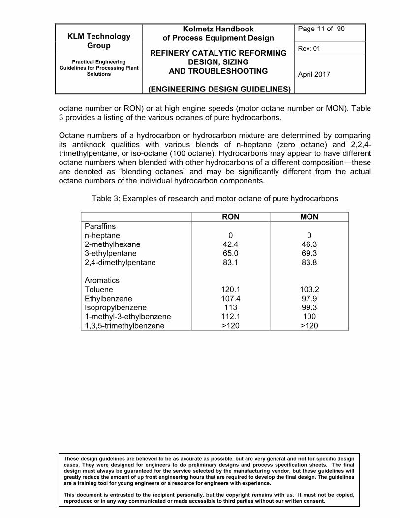
Feed hydrotreating is used to reduce feedstock contaminants to acceptable levels. Common poisons for reforming catalysts that are found in naphtha are sulfur, nitrogen, and oxygen compounds. Removing these requires breaking of a carbon-sulfur, -nitrogen
KLM Technology Group
Practical Engineering
Guidelines for Processing Plant Solutions
Kolmetz Handbook of Process Equipment Design
REFINERY CATALYTIC REFORMING DESIGN, SIZING
AND TROUBLESHOOTING
(ENGINEERING DESIGN GUIDELINES)
Page 10 of 90
Rev: 01
April 2017
These design guidelines are believed to be as accurate as possible, but are very general and not for specific design cases. They were designed for engineers to do preliminary designs and process specification sheets. The final design must always be guaranteed for the service selected by the manufacturing vendor, but these guidelines will greatly reduce the amount of up front engineering hours that are required to develop the final design. The guidelines are a training tool for young engineers or a resource for engineers with experience. This document is entrusted to the recipient personally, but the copyright remains with us. It must not be copied, reproduced or in any way communicated or made accessible to third parties without our written consent.
or -oxygen bond and formation of hydrogen sulfide, ammonia, or water, respectively. Hydrotreaters will also remove olefins and metal contaminants. The reformate stream from a catalytic reforming unit is invariably used either as a high octane gasoline blending component or as a source of aromatics—BTX (benzene, toluene, and xylenes), and C9+ aromatics. Reforming for motor fuel applications still represents the majority of existing reforming capacity. Reformate specifications (octane, vapor pressure, end point, etc.) are set to provide an optimum blending product. The octane requirement is met through the production of high-octane aromatics, the isomerization of paraffins, and the removal of low octane components by cracking them to gaseous products. Feedstocks to these units are typically “full range” naphtha, consisting of hydrocarbons with 6–12 carbon atoms; however, the initial boiling point may be varied to limit the presence of benzene precursors. Reforming units for the production of aromatics are often called BTX reformers. Naphtha for these units are specified to contain mostly naphthenes and paraffins of 6–8 carbons. The desired reaction is aromatization through dehydrogenation of the naphthenes, and cyclization and dehydrogenation of the paraffins to the analogous aromatic.
Figure 2: Sulfur types. Reformate properties For motor fuel applications, the octane number is the dominant parameter of product quality. A higher octane number reflects a lower tendency of the hydrocarbon to undergo a rapid, inefficient detonation in an internal combustion engine. This rapid detonation is heard as a knocking sound in the engine, so octane is often referred to as the antiknock quality of a gasoline. Motor fuel octanes are measured at low engine speeds (research
KLM Technology Group
Practical Engineering
Guidelines for Processing Plant Solutions
Kolmetz Handbook of Process Equipment Design
REFINERY CATALYTIC REFORMING DESIGN, SIZING
AND TROUBLESHOOTING
(ENGINEERING DESIGN GUIDELINES)
Page 11 of 90
Rev: 01
April 2017
These design guidelines are believed to be as accurate as possible, but are very general and not for specific design cases. They were designed for engineers to do preliminary designs and process specification sheets. The final design must always be guaranteed for the service selected by the manufacturing vendor, but these guidelines will greatly reduce the amount of up front engineering hours that are required to develop the final design. The guidelines are a training tool for young engineers or a resource for engineers with experience. This document is entrusted to the recipient personally, but the copyright remains with us. It must not be copied, reproduced or in any way communicated or made accessible to third parties without our written consent.
octane number or RON) or at high engine speeds (motor octane number or MON). Table 3 provides a listing of the various octanes of pure hydrocarbons. Octane numbers of a hydrocarbon or hydrocarbon mixture are determined by comparing its antiknock qualities with various blends of n-heptane (zero octane) and 2,2,4-trimethylpentane, or iso-octane (100 octane). Hydrocarbons may appear to have different octane numbers when blended with other hydrocarbons of a different composition—these are denoted as “blending octanes” and may be significantly different from the actual octane numbers of the individual hydrocarbon components.
Table 3: Examples of research and motor octane of pure hydrocarbons
These design guidelines are believed to be as accurate as possible, but are very general and not for specific design cases. They were designed for engineers to do preliminary designs and process specification sheets. The final design must always be guaranteed for the service selected by the manufacturing vendor, but these guidelines will greatly reduce the amount of up front engineering hours that are required to develop the final design. The guidelines are a training tool for young engineers or a resource for engineers with experience. This document is entrusted to the recipient personally, but the copyright remains with us. It must not be copied, reproduced or in any way communicated or made accessible to third parties without our written consent.
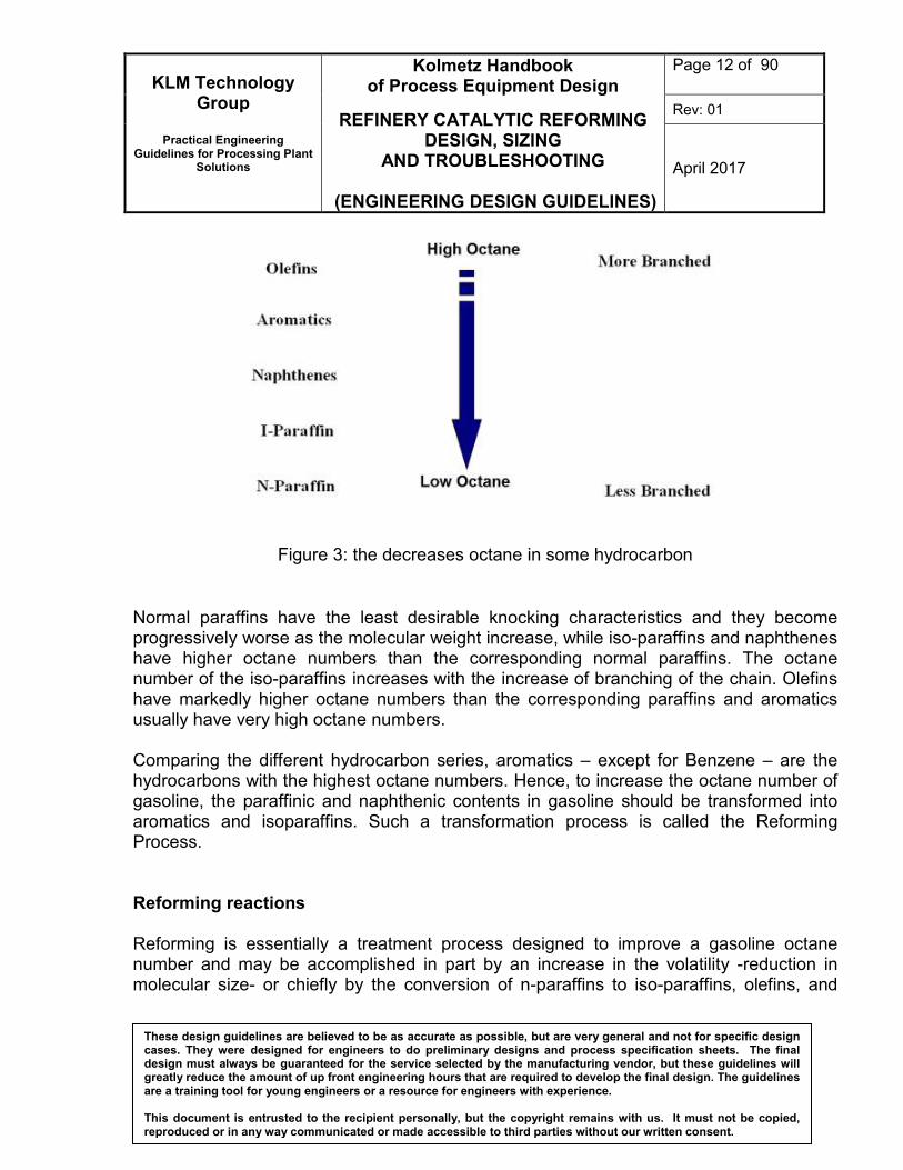
Figure 3: the decreases octane in some hydrocarbon
Normal paraffins have the least desirable knocking characteristics and they become progressively worse as the molecular weight increase, while iso-paraffins and naphthenes have higher octane numbers than the corresponding normal paraffins. The octane number of the iso-paraffins increases with the increase of branching of the chain. Olefins have markedly higher octane numbers than the corresponding paraffins and aromatics usually have very high octane numbers. Comparing the different hydrocarbon series, aromatics – except for Benzene – are the hydrocarbons with the highest octane numbers. Hence, to increase the octane number of gasoline, the paraffinic and naphthenic contents in gasoline should be transformed into aromatics and isoparaffins. Such a transformation process is called the Reforming Process. Reforming reactions Reforming is essentially a treatment process designed to improve a gasoline octane number and may be accomplished in part by an increase in the volatility -reduction in molecular size- or chiefly by the conversion of n-paraffins to iso-paraffins, olefins, and
KLM Technology Group
Practical Engineering
Guidelines for Processing Plant Solutions
Kolmetz Handbook of Process Equipment Design
REFINERY CATALYTIC REFORMING DESIGN, SIZING
AND TROUBLESHOOTING
(ENGINEERING DESIGN GUIDELINES)
Page 13 of 90
Rev: 01
April 2017
These design guidelines are believed to be as accurate as possible, but are very general and not for specific design cases. They were designed for engineers to do preliminary designs and process specification sheets. The final design must always be guaranteed for the service selected by the manufacturing vendor, but these guidelines will greatly reduce the amount of up front engineering hours that are required to develop the final design. The guidelines are a training tool for young engineers or a resource for engineers with experience. This document is entrusted to the recipient personally, but the copyright remains with us. It must not be copied, reproduced or in any way communicated or made accessible to third parties without our written consent.
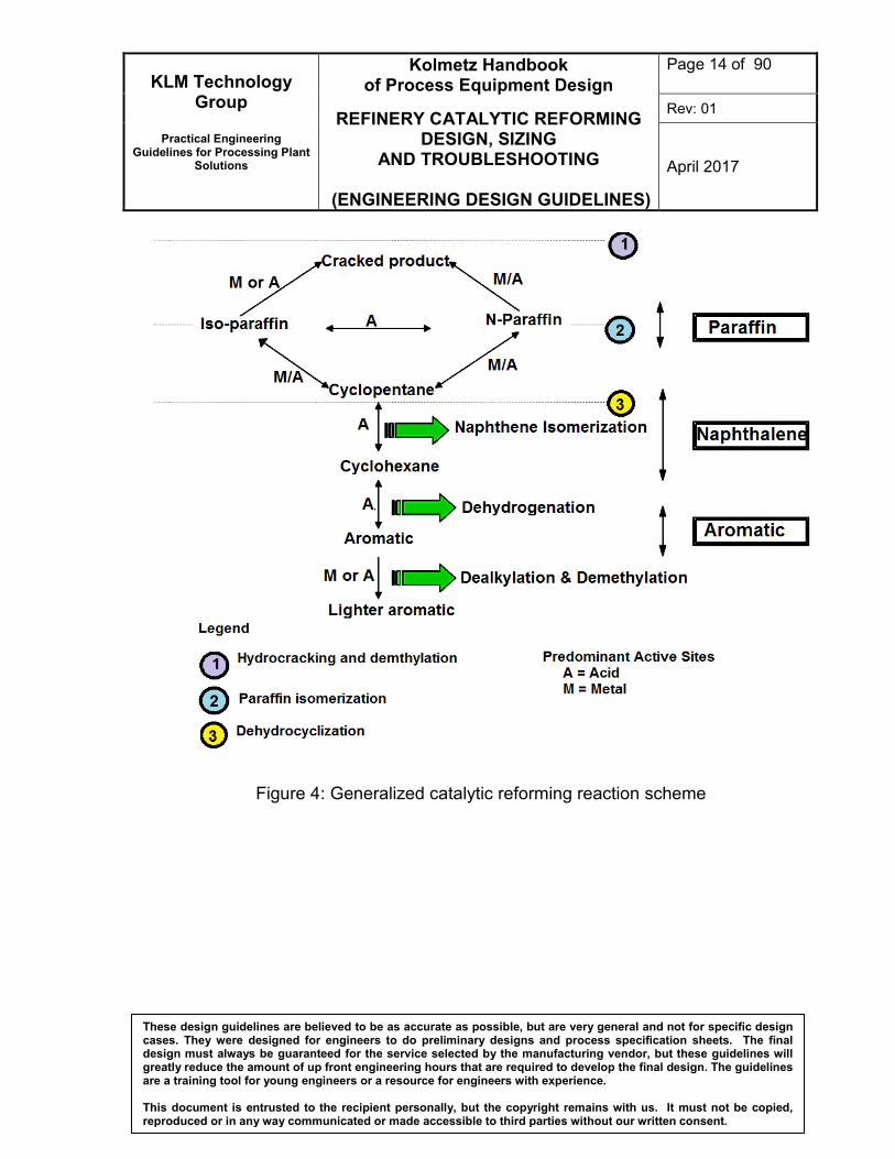
aromatics and the conversion of naphthenes to aromatics. Overall, the reforming reactions are endothermic. The resulting product stream (reformate) from catalytic reforming has a RON from 96 to 102 depending on the reactor severity and feedstock quality. The principal reforming reactions are the cracking of paraffins, paraffins isomerisation, dehydrocyclisation of paraffins to naphthenes and the dehydrogenation of naphthenes. The cyclisation and dehydrogenation reactions produce valuable aromatics. In BTX production, the objective is to transform paraffins and naphthenes into benzene, toluene, and xylenes with minimal cracking to light gases. The yield of desired product is the percentage of feed converted to these aromatics. In motor fuel applications, octane values of the feed may be raised via aromatization or through isomerization of the paraffins into higher octane branched species without sacrificing yield. Yield is typically defined as liquid product with five or more carbons. A generalized reaction scheme that identifies these key reactions, as well as the reaction pathways that are required to achieve high product yields, is depicted below. As shown, two key catalyst functions are served by acid and metal sites. The performance of the catalyst system, as measured by its activity and selectivity to the desired reactions, is a function of the balance achieved between these acid and metal sites.
KLM Technology Group
Practical Engineering
Guidelines for Processing Plant Solutions
Kolmetz Handbook of Process Equipment Design
REFINERY CATALYTIC REFORMING DESIGN, SIZING
AND TROUBLESHOOTING
(ENGINEERING DESIGN GUIDELINES)
Page 14 of 90
Rev: 01
April 2017
These design guidelines are believed to be as accurate as possible, but are very general and not for specific design cases. They were designed for engineers to do preliminary designs and process specification sheets. The final design must always be guaranteed for the service selected by the manufacturing vendor, but these guidelines will greatly reduce the amount of up front engineering hours that are required to develop the final design. The guidelines are a training tool for young engineers or a resource for engineers with experience. This document is entrusted to the recipient personally, but the copyright remains with us. It must not be copied, reproduced or in any way communicated or made accessible to third parties without our written consent.
These design guidelines are believed to be as accurate as possible, but are very general and not for specific design cases. They were designed for engineers to do preliminary designs and process specification sheets. The final design must always be guaranteed for the service selected by the manufacturing vendor, but these guidelines will greatly reduce the amount of up front engineering hours that are required to develop the final design. The guidelines are a training tool for young engineers or a resource for engineers with experience. This document is entrusted to the recipient personally, but the copyright remains with us. It must not be copied, reproduced or in any way communicated or made accessible to third parties without our written consent.
The reforming reactions are classified into eight general classes that include the following reversible reactions:
• Isomerisation of paraffins and naphthenes to form branched paraffins and naphthenes.
• Dehydrocyclisation or ring closure of paraffins to naphthenes and the ring opening of naphthenes.
• Ring expansion and ring contraction of naphthenes.
• Dehydrogenation of naphthenes to aromatics and hydrogenation of aromatics.
The kinetic model also includes the following irreversible reactions:
• Hydrogenolysis of paraffins to lighter paraffins and hydrogenolysis with hydrodealkylation of naphthenes to lighter naphthenes and paraffins.
• Hydrocracking of paraffins to lighter paraffins.
• Hydrodealkylation of aromatics to lighter aromatics and paraffins.
• Condensation of olefins and aromatics to coke.
Typical catalysts that consist of platinum supported on alumina (with or without other metals or modifiers) are bifunctional in that separate and distinct reactions occur on the platinum site and on the alumina. The platinum typically performs dehydrogenation and hydrogenolysis, while the acidic alumina isomerizes, cyclizes, and cracks. The dehydrogenation of naphthenes to aromatics is probably the most important reaction. Feeds contain cyclopentanes and substituted cyclopentanes, as well as cyclohexanes and their homologues. Six carbon ring cyclohexanes, for example, can be directly dehydrogenated to produce aromatics and hydrogen. Naphthene De-hydrogenation
Dehydrogenation is a main chemical reaction in catalytic reforming, and hydrogen gas is consequently produced in large quantities. The hydrogen is recycled through the reactors
KLM Technology Group
Practical Engineering
Guidelines for Processing Plant Solutions
Kolmetz Handbook of Process Equipment Design
REFINERY CATALYTIC REFORMING DESIGN, SIZING
AND TROUBLESHOOTING
(ENGINEERING DESIGN GUIDELINES)
Page 16 of 90
Rev: 01
April 2017
These design guidelines are believed to be as accurate as possible, but are very general and not for specific design cases. They were designed for engineers to do preliminary designs and process specification sheets. The final design must always be guaranteed for the service selected by the manufacturing vendor, but these guidelines will greatly reduce the amount of up front engineering hours that are required to develop the final design. The guidelines are a training tool for young engineers or a resource for engineers with experience. This document is entrusted to the recipient personally, but the copyright remains with us. It must not be copied, reproduced or in any way communicated or made accessible to third parties without our written consent.
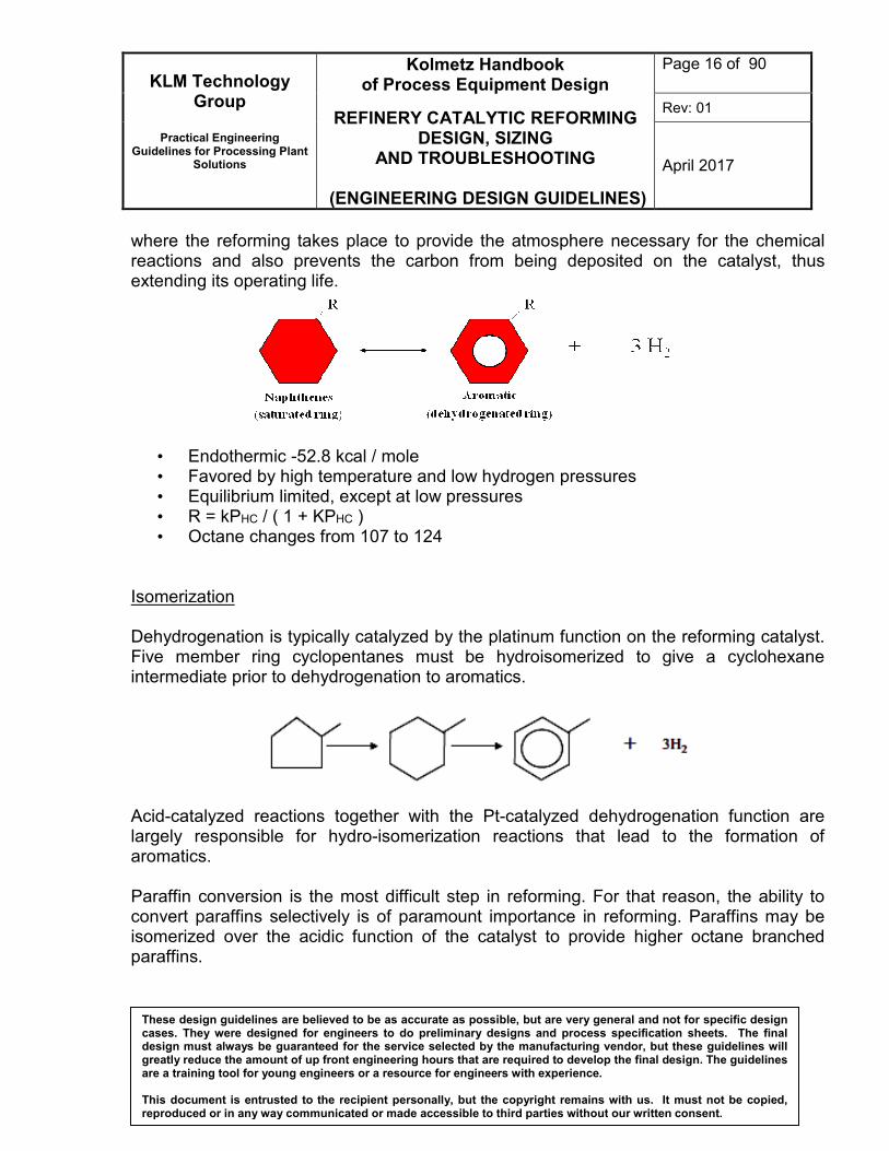
where the reforming takes place to provide the atmosphere necessary for the chemical reactions and also prevents the carbon from being deposited on the catalyst, thus extending its operating life.
• Endothermic -52.8 kcal / mole • Favored by high temperature and low hydrogen pressures • Equilibrium limited, except at low pressures • R = kPHC / ( 1 + KPHC ) • Octane changes from 107 to 124
Isomerization Dehydrogenation is typically catalyzed by the platinum function on the reforming catalyst. Five member ring cyclopentanes must be hydroisomerized to give a cyclohexane intermediate prior to dehydrogenation to aromatics.
Acid-catalyzed reactions together with the Pt-catalyzed dehydrogenation function are largely responsible for hydro-isomerization reactions that lead to the formation of aromatics. Paraffin conversion is the most difficult step in reforming. For that reason, the ability to convert paraffins selectively is of paramount importance in reforming. Paraffins may be isomerized over the acidic function of the catalyst to provide higher octane branched paraffins.
KLM Technology Group
Practical Engineering
Guidelines for Processing Plant Solutions
Kolmetz Handbook of Process Equipment Design
REFINERY CATALYTIC REFORMING DESIGN, SIZING
AND TROUBLESHOOTING
(ENGINEERING DESIGN GUIDELINES)
Page 17 of 90
Rev: 01
April 2017
These design guidelines are believed to be as accurate as possible, but are very general and not for specific design cases. They were designed for engineers to do preliminary designs and process specification sheets. The final design must always be guaranteed for the service selected by the manufacturing vendor, but these guidelines will greatly reduce the amount of up front engineering hours that are required to develop the final design. The guidelines are a training tool for young engineers or a resource for engineers with experience. This document is entrusted to the recipient personally, but the copyright remains with us. It must not be copied, reproduced or in any way communicated or made accessible to third parties without our written consent.
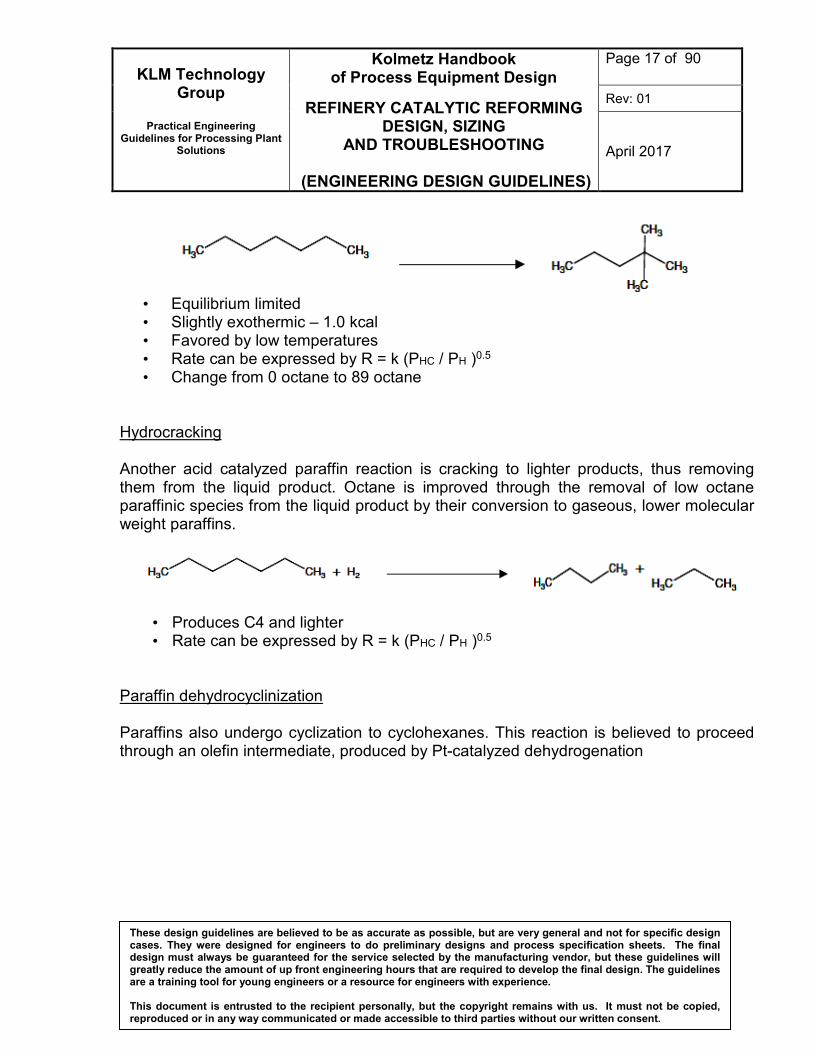
• Equilibrium limited • Slightly exothermic – 1.0 kcal • Favored by low temperatures • Rate can be expressed by R = k (PHC / PH )0.5 • Change from 0 octane to 89 octane
Hydrocracking Another acid catalyzed paraffin reaction is cracking to lighter products, thus removing them from the liquid product. Octane is improved through the removal of low octane paraffinic species from the liquid product by their conversion to gaseous, lower molecular weight paraffins.
• Produces C4 and lighter • Rate can be expressed by R = k (PHC / PH )0.5
Paraffin dehydrocyclinization Paraffins also undergo cyclization to cyclohexanes. This reaction is believed to proceed through an olefin intermediate, produced by Pt-catalyzed dehydrogenation
KLM Technology Group
Practical Engineering
Guidelines for Processing Plant Solutions
Kolmetz Handbook of Process Equipment Design
REFINERY CATALYTIC REFORMING DESIGN, SIZING
AND TROUBLESHOOTING
(ENGINEERING DESIGN GUIDELINES)
Page 18 of 90
Rev: 01
April 2017
These design guidelines are believed to be as accurate as possible, but are very general and not for specific design cases. They were designed for engineers to do preliminary designs and process specification sheets. The final design must always be guaranteed for the service selected by the manufacturing vendor, but these guidelines will greatly reduce the amount of up front engineering hours that are required to develop the final design. The guidelines are a training tool for young engineers or a resource for engineers with experience. This document is entrusted to the recipient personally, but the copyright remains with us. It must not be copied, reproduced or in any way communicated or made accessible to third parties without our written consent.
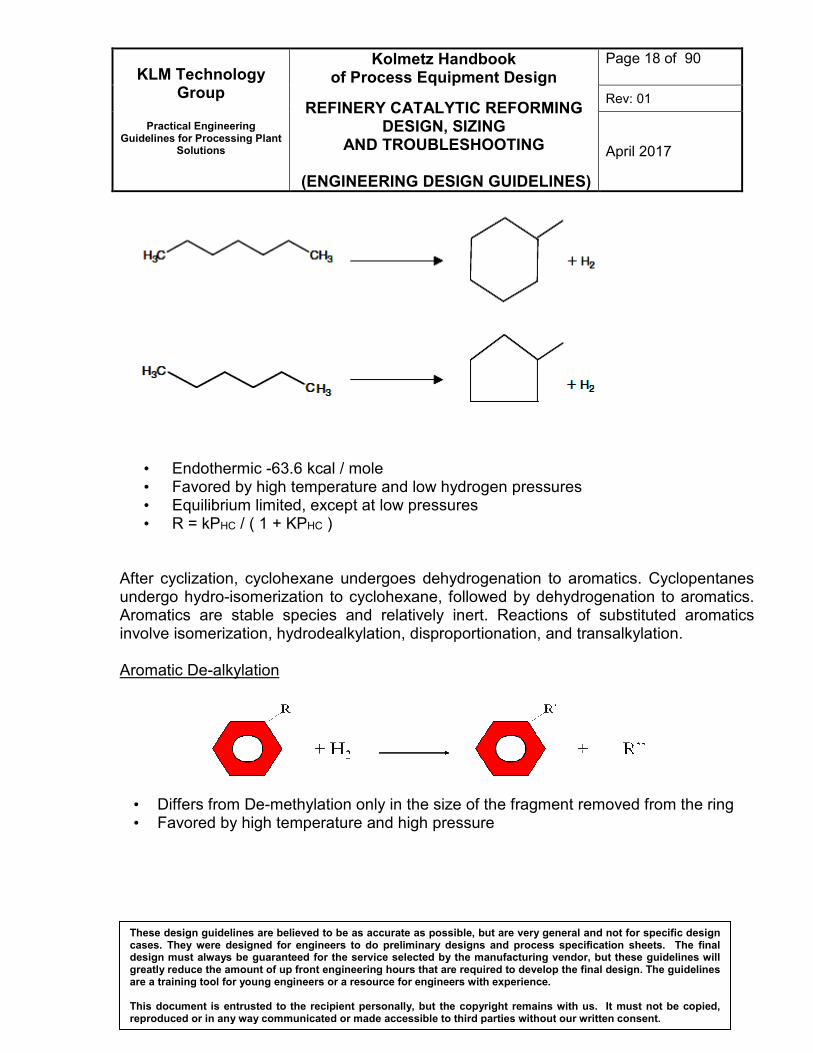
• Endothermic -63.6 kcal / mole • Favored by high temperature and low hydrogen pressures • Equilibrium limited, except at low pressures • R = kPHC / ( 1 + KPHC )
After cyclization, cyclohexane undergoes dehydrogenation to aromatics. Cyclopentanes undergo hydro-isomerization to cyclohexane, followed by dehydrogenation to aromatics. Aromatics are stable species and relatively inert. Reactions of substituted aromatics involve isomerization, hydrodealkylation, disproportionation, and transalkylation. Aromatic De-alkylation
• Differs from De-methylation only in the size of the fragment removed from the ring • Favored by high temperature and high pressure
KLM Technology Group
Practical Engineering
Guidelines for Processing Plant Solutions
Kolmetz Handbook of Process Equipment Design
REFINERY CATALYTIC REFORMING DESIGN, SIZING
AND TROUBLESHOOTING
(ENGINEERING DESIGN GUIDELINES)
Page 19 of 90
Rev: 01
April 2017
These design guidelines are believed to be as accurate as possible, but are very general and not for specific design cases. They were designed for engineers to do preliminary designs and process specification sheets. The final design must always be guaranteed for the service selected by the manufacturing vendor, but these guidelines will greatly reduce the amount of up front engineering hours that are required to develop the final design. The guidelines are a training tool for young engineers or a resource for engineers with experience. This document is entrusted to the recipient personally, but the copyright remains with us. It must not be copied, reproduced or in any way communicated or made accessible to third parties without our written consent.
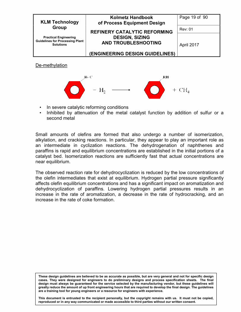
De-methylation
• In severe catalytic reforming conditions • Inhibited by attenuation of the metal catalyst function by addition of sulfur or a
second metal Small amounts of olefins are formed that also undergo a number of isomerization, alkylation, and cracking reactions. In particular, they appear to play an important role as an intermediate in cyclization reactions. The dehydrogenation of naphthenes and paraffins is rapid and equilibrium concentrations are established in the initial portions of a catalyst bed. Isomerization reactions are sufficiently fast that actual concentrations are near equilibrium. The observed reaction rate for dehydrocyclization is reduced by the low concentrations of the olefin intermediates that exist at equilibrium. Hydrogen partial pressure significantly affects olefin equilibrium concentrations and has a significant impact on aromatization and dehydrocyclization of paraffins. Lowering hydrogen partial pressures results in an increase in the rate of aromatization, a decrease in the rate of hydrocracking, and an increase in the rate of coke formation.
KLM Technology Group
Practical Engineering
Guidelines for Processing Plant Solutions
Kolmetz Handbook of Process Equipment Design
REFINERY CATALYTIC REFORMING DESIGN, SIZING
AND TROUBLESHOOTING
(ENGINEERING DESIGN GUIDELINES)
Page 20 of 90
Rev: 01
April 2017
These design guidelines are believed to be as accurate as possible, but are very general and not for specific design cases. They were designed for engineers to do preliminary designs and process specification sheets. The final design must always be guaranteed for the service selected by the manufacturing vendor, but these guidelines will greatly reduce the amount of up front engineering hours that are required to develop the final design. The guidelines are a training tool for young engineers or a resource for engineers with experience. This document is entrusted to the recipient personally, but the copyright remains with us. It must not be copied, reproduced or in any way communicated or made accessible to third parties without our written consent.
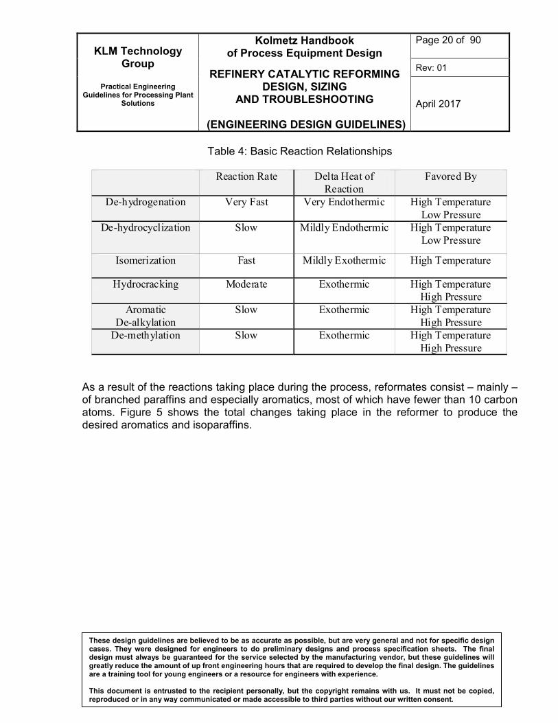
Table 4: Basic Reaction Relationships
Reaction Rate Delta Heat of
Reaction
Favored By
De-hydrogenation Very Fast Very Endothermic High Temperature
Low Pressure
De-hydrocyclization Slow Mildly Endothermic High Temperature
Low Pressure
Isomerization Fast Mildly Exothermic High Temperature
Hydrocracking Moderate Exothermic High Temperature
High Pressure
Aromatic
De-alkylation
Slow Exothermic High Temperature
High Pressure
De-methylation Slow Exothermic High Temperature
High Pressure
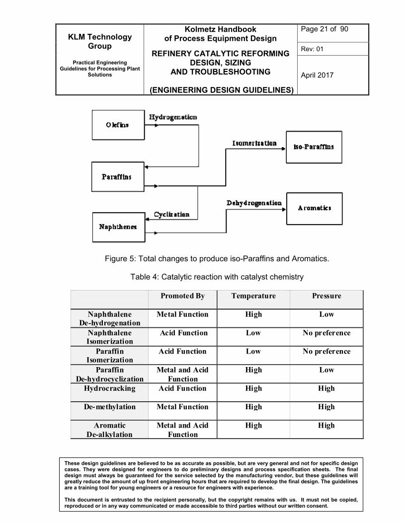
As a result of the reactions taking place during the process, reformates consist – mainly – of branched paraffins and especially aromatics, most of which have fewer than 10 carbon atoms. Figure 5 shows the total changes taking place in the reformer to produce the desired aromatics and isoparaffins.
KLM Technology Group
Practical Engineering
Guidelines for Processing Plant Solutions
Kolmetz Handbook of Process Equipment Design
REFINERY CATALYTIC REFORMING DESIGN, SIZING
AND TROUBLESHOOTING
(ENGINEERING DESIGN GUIDELINES)
Page 21 of 90
Rev: 01
April 2017
These design guidelines are believed to be as accurate as possible, but are very general and not for specific design cases. They were designed for engineers to do preliminary designs and process specification sheets. The final design must always be guaranteed for the service selected by the manufacturing vendor, but these guidelines will greatly reduce the amount of up front engineering hours that are required to develop the final design. The guidelines are a training tool for young engineers or a resource for engineers with experience. This document is entrusted to the recipient personally, but the copyright remains with us. It must not be copied, reproduced or in any way communicated or made accessible to third parties without our written consent.
Figure 5: Total changes to produce iso-Paraffins and Aromatics.
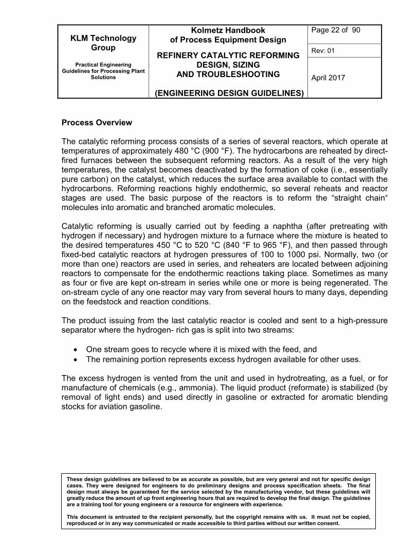
Table 4: Catalytic reaction with catalyst chemistry
Promoted By Temperature Pressure
Naphthalene De-hydrogenation
Metal Function High Low
Naphthalene Isomerization
Acid Function Low No preference
Paraffin Isomerization
Acid Function Low No preference
Paraffin
De-hydrocyclization
Metal and Acid
Function
High Low
Hydrocracking
Acid Function High High
De-methylation
Metal Function High High
Aromatic
De-alkylation
Metal and Acid
Function
High
High
KLM Technology Group
Practical Engineering
Guidelines for Processing Plant Solutions
Kolmetz Handbook of Process Equipment Design
REFINERY CATALYTIC REFORMING DESIGN, SIZING
AND TROUBLESHOOTING
(ENGINEERING DESIGN GUIDELINES)
Page 22 of 90
Rev: 01
April 2017
These design guidelines are believed to be as accurate as possible, but are very general and not for specific design cases. They were designed for engineers to do preliminary designs and process specification sheets. The final design must always be guaranteed for the service selected by the manufacturing vendor, but these guidelines will greatly reduce the amount of up front engineering hours that are required to develop the final design. The guidelines are a training tool for young engineers or a resource for engineers with experience. This document is entrusted to the recipient personally, but the copyright remains with us. It must not be copied, reproduced or in any way communicated or made accessible to third parties without our written consent.
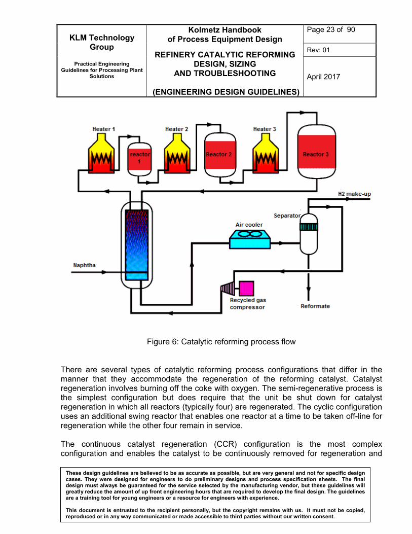
Process Overview The catalytic reforming process consists of a series of several reactors, which operate at temperatures of approximately 480 °C (900 °F). The hydrocarbons are reheated by direct-fired furnaces between the subsequent reforming reactors. As a result of the very high temperatures, the catalyst becomes deactivated by the formation of coke (i.e., essentially pure carbon) on the catalyst, which reduces the surface area available to contact with the hydrocarbons. Reforming reactions highly endothermic, so several reheats and reactor stages are used. The basic purpose of the reactors is to reform the “straight chain“ molecules into aromatic and branched aromatic molecules. Catalytic reforming is usually carried out by feeding a naphtha (after pretreating with hydrogen if necessary) and hydrogen mixture to a furnace where the mixture is heated to the desired temperatures 450 °C to 520 °C (840 °F to 965 °F), and then passed through fixed-bed catalytic reactors at hydrogen pressures of 100 to 1000 psi. Normally, two (or more than one) reactors are used in series, and reheaters are located between adjoining reactors to compensate for the endothermic reactions taking place. Sometimes as many as four or five are kept on-stream in series while one or more is being regenerated. The on-stream cycle of any one reactor may vary from several hours to many days, depending on the feedstock and reaction conditions. The product issuing from the last catalytic reactor is cooled and sent to a high-pressure separator where the hydrogen- rich gas is split into two streams:
• One stream goes to recycle where it is mixed with the feed, and
• The remaining portion represents excess hydrogen available for other uses. The excess hydrogen is vented from the unit and used in hydrotreating, as a fuel, or for manufacture of chemicals (e.g., ammonia). The liquid product (reformate) is stabilized (by removal of light ends) and used directly in gasoline or extracted for aromatic blending stocks for aviation gasoline.
KLM Technology Group
Practical Engineering
Guidelines for Processing Plant Solutions
Kolmetz Handbook of Process Equipment Design
REFINERY CATALYTIC REFORMING DESIGN, SIZING
AND TROUBLESHOOTING
(ENGINEERING DESIGN GUIDELINES)
Page 23 of 90
Rev: 01
April 2017
These design guidelines are believed to be as accurate as possible, but are very general and not for specific design cases. They were designed for engineers to do preliminary designs and process specification sheets. The final design must always be guaranteed for the service selected by the manufacturing vendor, but these guidelines will greatly reduce the amount of up front engineering hours that are required to develop the final design. The guidelines are a training tool for young engineers or a resource for engineers with experience. This document is entrusted to the recipient personally, but the copyright remains with us. It must not be copied, reproduced or in any way communicated or made accessible to third parties without our written consent.
Figure 6: Catalytic reforming process flow
There are several types of catalytic reforming process configurations that differ in the manner that they accommodate the regeneration of the reforming catalyst. Catalyst regeneration involves burning off the coke with oxygen. The semi-regenerative process is the simplest configuration but does require that the unit be shut down for catalyst regeneration in which all reactors (typically four) are regenerated. The cyclic configuration uses an additional swing reactor that enables one reactor at a time to be taken off-line for regeneration while the other four remain in service. The continuous catalyst regeneration (CCR) configuration is the most complex configuration and enables the catalyst to be continuously removed for regeneration and
KLM Technology Group
Practical Engineering
Guidelines for Processing Plant Solutions
Kolmetz Handbook of Process Equipment Design
REFINERY CATALYTIC REFORMING DESIGN, SIZING
AND TROUBLESHOOTING
(ENGINEERING DESIGN GUIDELINES)
Page 24 of 90
Rev: 01
April 2017
These design guidelines are believed to be as accurate as possible, but are very general and not for specific design cases. They were designed for engineers to do preliminary designs and process specification sheets. The final design must always be guaranteed for the service selected by the manufacturing vendor, but these guidelines will greatly reduce the amount of up front engineering hours that are required to develop the final design. The guidelines are a training tool for young engineers or a resource for engineers with experience. This document is entrusted to the recipient personally, but the copyright remains with us. It must not be copied, reproduced or in any way communicated or made accessible to third parties without our written consent.
replaced after regeneration. The benefits of more complex configurations are that operating severity may be increased as a result of higher catalyst activity but this does come at an increased capital cost for the process. Below are general design consideration of catalytic reformer
• Reactor inlet pressure typically 4 to 24 barg.
• Reactor inlet temperature typically 500 to 525˚C
• Hydrogen to feed ratio 5:1
• Coke formation decreases catalytic activity and catalyst needs to be regenerated
• Three types of operation, depending on catalyst regeneration:
• Semi regenerative: requires plant to be shut down for regeneration (every 3 to 24 months)
• Cyclic: - swing reactor in addition to ones on stream - swing reactor regenerated
- reactors switched when catalyst activity drops (without shutdown of plant)
• Continuous : continuous removal and regeneration of catalyst
• Modern designs use moving beds with continuous regeneration
KLM Technology Group
Practical Engineering
Guidelines for Processing Plant Solutions
Kolmetz Handbook of Process Equipment Design
REFINERY CATALYTIC REFORMING DESIGN, SIZING
AND TROUBLESHOOTING
(ENGINEERING DESIGN GUIDELINES)
Page 25 of 90
Rev: 01
April 2017
These design guidelines are believed to be as accurate as possible, but are very general and not for specific design cases. They were designed for engineers to do preliminary designs and process specification sheets. The final design must always be guaranteed for the service selected by the manufacturing vendor, but these guidelines will greatly reduce the amount of up front engineering hours that are required to develop the final design. The guidelines are a training tool for young engineers or a resource for engineers with experience. This document is entrusted to the recipient personally, but the copyright remains with us. It must not be copied, reproduced or in any way communicated or made accessible to third parties without our written consent.
DEFINITIONS Catalytic reforming - a process for improving the octane quality of straight-run naphtha and of mixed naphtha containing cracked naphtha Coke - formed in the processes to convert the residuum fuels to the more desirable distillate products of naphtha and lighter through to the middle distillates Crude oil - a mixture of hydrocarbon compounds. These compounds range in boiling points and molecular weights from methane as the lightest compound to those whose molecular weight will be in excess of 500. De-butanizers - A fractionator designed to separate butane (and more volatile components if present) from a hydrocarbon mixture De-butanizers are used in refineries to remove butanes and lighter compounds from product streams The material balance - the process represented by the process flow diagram is either shown in table form on the bottom of the flow sheet or on an attached but separate table Octane numbers - a measure of a gasoline’ s resistance to knock or detonation in a cylinder of a gasoline engine. The higher this resistance is the higher will be the efficiency of the fuel to produce work. Regenerator - A unit including reboiler, still column and other related facilities to regenerate (or re-concentrate) Heat duty - The rate of heat absorption by the process. Excess Air - The percentage of air in the heater in excess of the stoichiometric amount required for combustion Exothermic - A process or reaction that release heat, i.e. a process or reaction for which the change in enthalpy, ΔH, isnegative at constant pressure and temperature Lower Heating Value (LHV) - The theoretical heat of combustion of a fuel, when no credit is taken for the heat of condensation of water in the flue gas.
KLM Technology Group
Practical Engineering
Guidelines for Processing Plant Solutions
Kolmetz Handbook of Process Equipment Design
REFINERY CATALYTIC REFORMING DESIGN, SIZING
AND TROUBLESHOOTING
(ENGINEERING DESIGN GUIDELINES)
Page 26 of 90
Rev: 01
April 2017
These design guidelines are believed to be as accurate as possible, but are very general and not for specific design cases. They were designed for engineers to do preliminary designs and process specification sheets. The final design must always be guaranteed for the service selected by the manufacturing vendor, but these guidelines will greatly reduce the amount of up front engineering hours that are required to develop the final design. The guidelines are a training tool for young engineers or a resource for engineers with experience. This document is entrusted to the recipient personally, but the copyright remains with us. It must not be copied, reproduced or in any way communicated or made accessible to third parties without our written consent.
Naphtha - Any of several highly volatile, flammable liquid mixtures of hydrocarbons distilled from petroleum, coal tar, and natural gas and used as fuel, as solvents, and in making various chemicals. Olefin - Any of a class of unsaturated open-chain hydrocarbons such as ethylene, having the general formula CnH2n; an alkene with only one carbon-carbon double bond. Pressure drops - the difference in pressure between two points of a fluid carrying network. Pressure drop occurs when frictional forces, caused by the resistance to flow Catalyst - A substance, usually used in small amounts relative to the reactants, that modifies and increases the rate of a reaction without being consumed in the process. Catalytic - Causing a chemical reaction to happen more quickly Aromatic molecules - Any of a large class of organic compounds whose molecular structure includes one or more planar rings of atoms, usually but not always six carbon atoms. The ring's carbon-carbon bonds (bonding) are neither single nor double but a type characteristic of these compounds, in which electrons are shared equally with all the atoms around the ring in an electron cloud. Space velocity - The relationship between feed rate and reactor volume in a flow process; defined as the volume or weight of feed (measured at standard conditions) per unit time per unit volume of reactor (or per unit weight of catalyst).
KLM Technology Group
Practical Engineering
Guidelines for Processing Plant Solutions
Kolmetz Handbook of Process Equipment Design
REFINERY CATALYTIC REFORMING DESIGN, SIZING
AND TROUBLESHOOTING
(ENGINEERING DESIGN GUIDELINES)
Page 27 of 90
Rev: 01
April 2017
These design guidelines are believed to be as accurate as possible, but are very general and not for specific design cases. They were designed for engineers to do preliminary designs and process specification sheets. The final design must always be guaranteed for the service selected by the manufacturing vendor, but these guidelines will greatly reduce the amount of up front engineering hours that are required to develop the final design. The guidelines are a training tool for young engineers or a resource for engineers with experience. This document is entrusted to the recipient personally, but the copyright remains with us. It must not be copied, reproduced or in any way communicated or made accessible to third parties without our written consent.
NOMENCLATURE % H2 % H2 in Naphtha (w/w), %
%(C1+C2) % (C1 + C2) in Naphtha (w/w), %
%C3 % C3 in Naphtha (w/w), %
%C4 % C4 in Naphtha (v/v), %
%C5+ % C5+ in Naphtha (v/v), %
%excess Excess air, %
%naphtha % naphtha in crude, %
Cao concentration at XA=0, lbmol/ft3
D Diameter of reactor, ft
FAo molar flow rate in, lbmol/h
GC5+ Volume flowrate of C5+, ft3/h
Gnaphtha Volume flowrate of naphtha, ft3/h
HFG enthalpy flue gas, btu/lb
L Length of reactor, ft
LHV LHV fuel gas, btu/lb
Mr Mass molecule naphtha
nXA=0 order of reaction at XA=0, lbmol
nXA=1 order of reaction at XA=1, lbmol
P Pressure, psia
Qduty Duty, btu/h
Qfired Heat fired, btu/h
rec.H2 H2 recycle, lbmol H2/lb naphtha
SGC5+ Specific gravity of C5+
SGn Specific gravity of naphtha
T Temperature, F
TFG Flue gas temperature, F
Tm Mean temperature, F
V Volume of reactor, ft3
KLM Technology Group
Practical Engineering
Guidelines for Processing Plant Solutions
Kolmetz Handbook of Process Equipment Design
REFINERY CATALYTIC REFORMING DESIGN, SIZING
AND TROUBLESHOOTING
(ENGINEERING DESIGN GUIDELINES)
Page 28 of 90
Rev: 01
April 2017
These design guidelines are believed to be as accurate as possible, but are very general and not for specific design cases. They were designed for engineers to do preliminary designs and process specification sheets. The final design must always be guaranteed for the service selected by the manufacturing vendor, but these guidelines will greatly reduce the amount of up front engineering hours that are required to develop the final design. The guidelines are a training tool for young engineers or a resource for engineers with experience. This document is entrusted to the recipient personally, but the copyright remains with us. It must not be copied, reproduced or in any way communicated or made accessible to third parties without our written consent.