65
Property Services Design Standard Brief Section 10 – Communications Issue 7.1 March 2017 Doc ID Version: 7.1 Status: Final Author: Andres Machado Updated By: BTP University Operations
| Date post: | 05-Sep-2018 |
| Category: |
Documents |
| Upload: | truongtuong |
| View: | 216 times |
| Download: | 0 times |

Property Services
Design Standard Brief
Section 10 – Communications
Issue 7.1
March 2017
Doc ID Version: 7.1 Status: Final Author: Andres Machado Updated By: BTP University
Operations

Section 10 – Communications
Design Standard Brief Section 10 Page 2 Issue No. 7.1, 2017
©Copyright | RMIT University, Melbourne, Australia 1997 | ALL RIGHTS RESERVED
Document Control
Document Author(s)
Name Role Contact Details
BTP team Architecture [email protected]
Revision History
Version Date Comment Editor
2003 Category 6 option included Network Architect
2006 Minor updates – UTP standards Network Architect
2007 New racking standards added Network Architect
2009 Revised Optical Fiber cabling options and augmented category 6a cabling
Network Architect
7.0 05/2014 Major Release – Revised for Optical Fiber, larger racks, and including patch by exception pilot
Glen Smith
7.1 21/03/2017 Updated communication rack standards and patterns, removal of Patch by exemption pilot, general structure updates across whole document
Andres Machado
Section 10 – Communications
Design Standard Brief Section 10 Page 3 Issue No. 7.1, 2017
©Copyright | RMIT University, Melbourne, Australia 1997 | ALL RIGHTS RESERVED
Contents10.1 INTRODUCTION .................................................................................................................................................... 7
10.1.1 PURPOSE ..................................................................................................................................................... 7
10.1.2 EXCLUSIONS ................................................................................................................................................ 7
10.1.3 CLARIFICATION, OMISSIONS, CONFLICT OF INFORMATION ........................................................................... 7
10.1.4 NO SUBSTITUTION OF PARTS ....................................................................................................................... 7
10.2 CONTENT STRUCTURE ..................................................................................................................................... 8
10.3 STANDARDS & REGULATIONS .......................................................................................................................... 9
10.3.1 AUSTRALIAN STANDARDS ........................................................................................................................... 10
10.3.2 AS/CA TECHNICAL STANDARDS & CODES .................................................................................................... 10
10.3.3 INTERNATIONAL STANDARDS ..................................................................................................................... 11
10.3.4 AUTHORITIES ............................................................................................................................................. 11
10.4 COMMUNICATION ROOMS ............................................................................................................................. 12
10.4.1 BUILDING COMMUNICATIONS ROOM ........................................................................................................ 12
10.4.1.2 Building Room Standards ......................................................................................................................................... 12 10.4.1.3 Cabling pathway standards ...................................................................................................................................... 13 10.4.1.4 Rack Requirements .................................................................................................................................................. 13 10.4.1.5 Cooling requirements ............................................................................................................................................... 14 10.4.1.6 Mains Power & Earthing Requirements ................................................................................................................... 14 10.4.1.7 Central Building UPS ................................................................................................................................................ 14 10.4.1.8 Building Communication Room UPS ........................................................................................................................ 15 10.4.1.9 Telephony Cabling Requirements ............................................................................................................................ 15 10.4.1.10 Optical Fiber Cabling Requirements .................................................................................................................... 15 10.4.1.11 Building Communication Room UPS ................................................................................................................... 16 10.4.1.12 Labelling Requirements ....................................................................................................................................... 16 10.4.1.13 Documentation ................................................................................................................................................... 17 10.4.1.14 Handover & Acceptance Testing ......................................................................................................................... 17 10.4.1.15 Additional Relevant Sections ............................................................................................................................... 17
10.4.2 FLOOR COMMUNICATIONS ROOM ............................................................................................................. 18
10.4.2.1 General Requirements ............................................................................................................................................. 18 10.4.2.2 Floor Room Standards .............................................................................................................................................. 19 10.4.2.3 Cable Pathway Standards (Floor rooms) .................................................................................................................. 20 10.4.2.4 Rack Requirements .................................................................................................................................................. 20 10.4.2.5 Patching Pattern – Rack Front .................................................................................................................................. 21 10.4.2.6 Patching Pattern – Rack Back ................................................................................................................................... 23 10.4.2.7 Cooling ..................................................................................................................................................................... 23 10.4.2.8 Mains Power & Earthing Requirements ................................................................................................................... 24 10.4.2.9 Central Building UPS ................................................................................................................................................ 24 10.4.2.10 Floor Communication Room UPS ........................................................................................................................ 24 10.4.2.11 Telephony Cabling Requirements – Floor Room ................................................................................................. 25 10.4.2.12 Optical Fiber Cabling ........................................................................................................................................... 25 10.4.2.13 Horizontal Cabling ............................................................................................................................................... 26 10.4.2.14 Labelling .............................................................................................................................................................. 26 10.4.2.15 Documentation ................................................................................................................................................... 26 10.4.2.16 Handover & Acceptance Testing .......................................................................................................................... 26 10.4.2.17 Additional Relevant Sections ............................................................................................................................... 28
10.4.3 COMMUNICATION/VERTICAL RISERS .......................................................................................................... 28
10.4.3.1 Labelling ................................................................................................................................................................... 28

Section 10 – Communications
Design Standard Brief Section 10 Page 4 Issue No. 7.1, 2017
©Copyright | RMIT University, Melbourne, Australia 1997 | ALL RIGHTS RESERVED
10.4.3.2 Handover and Acceptance Testing ........................................................................................................................... 28
10.5 OPTICAL FIBRE CABLING ................................................................................................................................. 29
10.5.1 OPTICAL FIBRE CABLE SPECIFICATIONS ....................................................................................................... 29
10.5.2 OPTICAL CABLING INSTALLATION STANDARDS............................................................................................ 29
10.5.3 PRE‐TERMINATED OPTICAL FIBERS ............................................................................................................. 30
10.5.4 COLOURS FOR OPTICAL FIBRE ADAPTORS, CONNECTORS AND CABLES ........................................................ 30
10.5.5 OPTICAL FIBRE LINK TESTING ...................................................................................................................... 30
10.5.6 TEST RESULTS OF OPTICAL FIBRE TESTING ................................................................................................... 31
10.5.7 FIBER OPTIC BREAK OUT TRAYS (FOBOT) .................................................................................................... 31
10.5.8 BUILDING COMMUNICATION ROOM FOBOT ............................................................................................... 31
10.5.9 FLOOR COMMUNICATION ROOM FOBOT .................................................................................................... 31
10.5.10 FIBER SPLICING ........................................................................................................................................... 31
10.5.11 OPTICAL FIBRE PATCH CORDS ..................................................................................................................... 32
10.5.12 LABELLING OF FOBOT ................................................................................................................................. 32
10.5.13 AS BUILT DOCUMENTATION & ACCEPTANCE TESTING ................................................................................. 33
10.6 UNSHIELDED TWISTED PAIR (UTP) CABLING .................................................................................................... 33
10.6.1 UTP CABLE SPECIFICATIONS ........................................................................................................................ 33
10.6.2 UTP CABLE TERMINATIONS ........................................................................................................................ 33
10.6.3 COPPER SYSTEM TAILS / PATCH/ FLY LEADS ................................................................................................ 33
10.6.4 OUTLET TYPE .............................................................................................................................................. 33
10.6.5 MOUNTING ................................................................................................................................................ 34
10.6.6 UTP CABLE INSTALLATIONS ........................................................................................................................ 34
10.6.7 TESTING OF UTP CABLING ........................................................................................................................... 34
10.6.8 INSTALLER .................................................................................................................................................. 35
10.6.9 LABELLING .................................................................................................................................................. 35
10.6.10 ACCEPTANCE TESTING AND HANDOVER ..................................................................................................... 35
10.6.11 DOCUMENTATION ...................................................................................................................................... 35
10.6.12 TELECOMMUNICATION OUTLETS REQUIREMENTS ...................................................................................... 35
10.7 TELEPHONY SYSTEMS ..................................................................................................................................... 36
10.7.1 TELEPHONE HANDSETS ............................................................................................................................... 36
10.8 ANALOGUE TELEPHONE DISTRIBUTION CABLING ............................................................................................. 36
10.8.1 ANALOGUE TELEPHONE CABLING ............................................................................................................... 36
10.8.2 INTER BUILDING AND INTERNAL MDF CABLING .......................................................................................... 37
10.8.3 INTRA BUILDING CABLING .......................................................................................................................... 37
10.8.4 RETAIL TENANCY ........................................................................................................................................ 37
10.8.5 TESTING OF TELEPHONY CABLES ................................................................................................................. 37
10.8.6 TELEPHONE DISTRIBUTION FRAME RECORDS .............................................................................................. 38
10.8.7 LABELLING .................................................................................................................................................. 38
10.8.8 DOCUMENTATION FOR RETAIL TENANCY .................................................................................................... 38

Section 10 – Communications
Design Standard Brief Section 10 Page 5 Issue No. 7.1, 2017
©Copyright | RMIT University, Melbourne, Australia 1997 | ALL RIGHTS RESERVED
10.8.9 PERMITTED ATTACHMENTS ........................................................................................................................ 38
10.8.10 HANDOVER ................................................................................................................................................ 38
10.9 BUILDING DISTRIBUTION FRAME (BD)............................................................................................................. 38
10.10 BUILDING LEAD IN, PITS, PIPES ................................................................................................................... 40
10.11 POWER AT DESKS. ...................................................................................................................................... 42
10.12 WIRELESS ACCESS POINTS ........................................................................................................................... 42
10.13 PHYSICAL SERVER APPLICATIONS ................................................................................................................ 42
10.14 IP ADDRESS ALLOCATION FOR DEVICES ....................................................................................................... 42
10.15 TENANT LOCATIONS ................................................................................................................................... 43
10.16 HAND OVER AT PROJECT COMPLETION ....................................................................................................... 43
10.17 MINOR AUGMENTATION OR PARTIAL RENOVATION < 20% OF EXISTING FLOOR AREA ................................ 44
10.17.1 OVERVIEW ................................................................................................................................................. 44
10.17.2 FLOOR COMMUNICATION ROOM ............................................................................................................... 44
10.17.2.1 Power .................................................................................................................................................................. 45 10.17.2.2 Cooling ................................................................................................................................................................ 45 10.17.4.1 Telephony Systems .............................................................................................................................................. 46 10.17.4.2 Analogue Telephone Cabling ............................................................................................................................... 46 10.17.4.3 Permitted Attachments ....................................................................................................................................... 46 10.17.4.4 Testing ................................................................................................................................................................. 46 10.17.4.5 Documentation ................................................................................................................................................... 46
10.17.5 CATEGORY 6 UNSHIELDED TWISTED PAIR (UTP) CABLING ............................................................................ 46
10.17.5.1 UTP Installations .................................................................................................................................................. 46 10.17.5.2 Installation Constraints ....................................................................................................................................... 47 10.17.5.3 Connector Specification ...................................................................................................................................... 48 10.17.5.4 Testing Category 6 ............................................................................................................................................... 48 10.17.5.5 Documentation ................................................................................................................................................... 49 10.17.5.6 Handover/Acceptance Testing ............................................................................................................................ 49
10.17.6 OPTICAL FIBER CABLING ............................................................................................................................. 49
10.17.6.1 Trunk Cables (Building Interconnections) ............................................................................................................ 49 10.17.6.2 Network Interconnection .................................................................................................................................... 49 10.17.6.3 Fibre Termination Points ...................................................................................................................................... 49 10.17.6.4 Fibre Splicing ....................................................................................................................................................... 49 10.17.6.5 Fibre Cable Labelling ........................................................................................................................................... 49 10.17.6.6 Optic Fibre Cabling Testing .................................................................................................................................. 49 10.17.6.7 Installation Documentation and Hand Over ........................................................................................................ 49 10.17.6.8 As Built Drawings and Manuals ........................................................................................................................... 49 10.17.6.9 Certification and Guarantee ................................................................................................................................ 49
10.18 DECOMMISSIONING ................................................................................................................................... 50
APPENDIX 10.A.1 BUILDING COMMUNICATION ROOM LAYOUT .................................................................................. 51
APPENDIX 10.A.2 FLOOR COMMUNICATION ROOM (FLOOR <600 GROSS M2) ............................................................. 52
APPENDIX 10.A.3 FLOOR COMMUNICATION ROOM (GROSS 600 M2 TO 2000 M2)....................................................... 53
APPENDIX 10.A.4 LEGACY COMMUNICATION ROOM RACK LAYOUT ............................................................................ 54
APPENDIX 10.A.5 FLOOR COMMUNICATION ROOM RACK LAYOUT (<600M2 FLOORS) ................................................. 55
APPENDIX 10.A.6 FLOOR COMMUNICATION ROOM RACK LAYOUT (>600M2 TO 2000M2 FLOORS) .............................. 56
APPENDIX 10.A.7 BUILDING COMMUNICATION ROOM RACK LAYOUT ......................................................................... 57
APPENDIX 10.A.8 BUILDING COMMUNICATIONS ROOM – TELEPHONE DISTRIBUTION FRAME LAYOUT ........................ 58

Section 10 – Communications
Design Standard Brief Section 10 Page 6 Issue No. 7.1, 2017
©Copyright | RMIT University, Melbourne, Australia 1997 | ALL RIGHTS RESERVED
APPENDIX 10.A.9 FLOOR COMMUNICATIONS ROOM UPS AND POWER ....................................................................... 59
APPENDIX 10.A.10 TELEPHONE DISTRIBUTION CABLE SCHEMATIC ............................................................................... 60
APPENDIX 10.A.11 FIBRE OPTIC CABLE SCHEMATIC ..................................................................................................... 61
APPENDIX 10.A.12 FOBOT BUILDING COMMUNICATIONS ROOM ................................................................................ 62
APPENDIX 10.A.13 FOBOT FLOOR COMMUNICATIONS ROOM ..................................................................................... 63
10.1 INTRODUCTION .................................................................................................................................................... 9
10.1.1 PURPOSE ..................................................................................................................................................... 9
10.1.2 EXCLUSIONS ................................................................................................................................................ 9
10.1.3 CLARIFICATION, OMISSIONS, CONFLICT OF INFORMATION ........................................................................... 9
10.1.4 NO SUBSTITUTION OF PARTS ....................................................................................................................... 9
10.2 CONTENT STRUCTURE .................................................................................................................................... 10
10.3 STANDARDS & REGULATIONS ......................................................................................................................... 11
10.3.1 AUSTRALIAN STANDARDS ........................................................................................................................... 12
10.3.2 AS/CA TECHNICAL STANDARDS & CODES .................................................................................................... 12
10.3.3 INTERNATIONAL STANDARDS ..................................................................................................................... 13
10.3.4 AUTHORITIES ............................................................................................................................................. 13
10.4 COMMUNICATION ROOMS ............................................................................................................................. 14
10.4.1 BUILDING COMMUNICATIONS ROOM ........................................................................................................ 14
10.4.2 FLOOR COMMUNICATIONS ROOM ............................................................................................................. 20
10.3.2 ......................................................................................................................................................................... 20
10.4.3 COMMUNICATION/VERTICAL RISERS .......................................................................................................... 30
10.5 OPTICAL FIBRE CABLING ................................................................................................................................. 31
10.5.1 OPTICAL FIBRE CABLE SPECIFICATIONS ....................................................................................................... 31
10.5.2 OPTICAL CABLING INSTALLATION STANDARDS............................................................................................ 31
10.5.3 PRE‐TERMINATED OPTICAL FIBERS ............................................................................................................. 32
10.5.4 COLOURS FOR OPTICAL FIBRE ADAPTORS, CONNECTORS AND CABLES ........................................................ 32
10.5.5 OPTICAL FIBRE LINK TESTING ...................................................................................................................... 32
10.5.6 TEST RESULTS OF OPTICAL FIBRE TESTING ................................................................................................... 33
10.5.7 FIBER OPTIC BREAK OUT TRAYS (FOBOT) .................................................................................................... 33
10.5.8 BUILDING COMMUNICATION ROOM FOBOT ............................................................................................... 33
10.5.9 FLOOR COMMUNICATION ROOM FOBOT .................................................................................................... 33
10.5.10 FIBER SPLICING ........................................................................................................................................... 33
10.5.11 OPTICAL FIBRE PATCH CORDS ..................................................................................................................... 34
10.5.12 LABELLING OF FOBOT ................................................................................................................................. 34
10.5.13 AS BUILT DOCUMENTATION & ACCEPTANCE TESTING ................................................................................. 35
10.6 UNSHIELDED TWISTED PAIR (UTP) CABLING .................................................................................................... 35
10.6.1 UTP CABLE SPECIFICATIONS ........................................................................................................................ 35

Section 10 – Communications
Design Standard Brief Section 10 Page 7 Issue No. 7.1, 2017
©Copyright | RMIT University, Melbourne, Australia 1997 | ALL RIGHTS RESERVED
10.6.2 UTP CABLE TERMINATIONS ........................................................................................................................ 35
10.6.3 COPPER SYSTEM TAILS / PATCH/ FLY LEADS ................................................................................................ 35
10.6.4 OUTLET TYPE .............................................................................................................................................. 35
10.6.5 MOUNTING ................................................................................................................................................ 36
10.6.6 UTP CABLE INSTALLATIONS ........................................................................................................................ 36
10.6.7 TESTING OF UTP CABLING ........................................................................................................................... 36
10.6.8 INSTALLER .................................................................................................................................................. 37
10.6.9 LABELLING .................................................................................................................................................. 37
10.6.10 ACCEPTANCE TESTING AND HANDOVER ..................................................................................................... 37
10.6.11 DOCUMENTATION ...................................................................................................................................... 37
10.6.12 TELECOMMUNICATION OUTLETS REQUIREMENTS ...................................................................................... 37
10.7 TELEPHONY SYSTEMS ..................................................................................................................................... 38
10.7.1 TELEPHONE HANDSETS ............................................................................................................................... 38
10.8 ANALOGUE TELEPHONE DISTRIBUTION CABLING ............................................................................................. 38
10.8.1 ANALOGUE TELEPHONE CABLING ............................................................................................................... 38
10.8.2 INTER BUILDING AND INTERNAL MDF CABLING .......................................................................................... 39
10.8.3 INTRA BUILDING CABLING .......................................................................................................................... 39
10.8.4 RETAIL TENANCY ........................................................................................................................................ 39
10.8.5 TESTING OF TELEPHONY CABLES ................................................................................................................. 39
10.8.6 TELEPHONE DISTRIBUTION FRAME RECORDS .............................................................................................. 40
10.8.7 LABELLING .................................................................................................................................................. 40
10.8.8 DOCUMENTATION FOR RETAIL TENANCY .................................................................................................... 40
10.8.9 PERMITTED ATTACHMENTS ........................................................................................................................ 40
10.8.10 HANDOVER ................................................................................................................................................ 40
10.9 BUILDING DISTRIBUTION FRAME (BD)............................................................................................................. 40
10.10 BUILDING LEAD IN, PITS, PIPES ................................................................................................................... 42
10.11 POWER AT DESKS. ...................................................................................................................................... 44
10.12 WIRELESS ACCESS POINTS ........................................................................................................................... 44
10.13 PHYSICAL SERVER APPLICATIONS ................................................................................................................ 44
10.14 IP ADDRESS ALLOCATION FOR DEVICES ....................................................................................................... 44
10.15 TENANT LOCATIONS ................................................................................................................................... 45
10.16 HAND OVER AT PROJECT COMPLETION ....................................................................................................... 45
10.17 MINOR AUGMENTATION OR PARTIAL RENOVATION < 20% OF EXISTING FLOOR AREA ................................ 46
10.17.1 OVERVIEW ................................................................................................................................................. 46
10.17.2 FLOOR COMMUNICATION ROOM ............................................................................................................... 46
10.17.5 CATEGORY 6 UNSHIELDED TWISTED PAIR (UTP) CABLING ............................................................................ 48
10.17.6 OPTICAL FIBER CABLING ............................................................................................................................. 51
10.18 DECOMMISSIONING ................................................................................................................................... 52

Section 10 – Communications
Design Standard Brief Section 10 Page 8 Issue No. 7.1, 2017
©Copyright | RMIT University, Melbourne, Australia 1997 | ALL RIGHTS RESERVED
APPENDIX 10.A.1 BUILDING COMMUNICATION ROOM LAYOUT .................................................................................. 53
APPENDIX 10.A.2 FLOOR COMMUNICATION ROOM (FLOOR <600 GROSS M2) ............................................................. 54
APPENDIX 10.A.3 FLOOR COMMUNICATION ROOM (GROSS 600 M2 TO 2000 M2)....................................................... 55
APPENDIX 10.A.4 LEGACY COMMUNICATION ROOM RACK LAYOUT ............................................................................ 56
APPENDIX 10.A.5 FLOOR COMMUNICATION ROOM RACK LAYOUT (<600M2 FLOORS) ................................................. 57
APPENDIX 10.A.6 FLOOR COMMUNICATION ROOM RACK LAYOUT (>600M2 TO 2000M2 FLOORS) .............................. 58
APPENDIX 10.A.7 BUILDING COMMUNICATION ROOM RACK LAYOUT ......................................................................... 59
APPENDIX 10.A.8 BUILDING COMMUNICATIONS ROOM – TELEPHONE DISTRIBUTION FRAME LAYOUT ........................ 60
APPENDIX 10.A.9 FLOOR COMMUNICATIONS ROOM UPS AND POWER ....................................................................... 61
APPENDIX 10.A.10 TELEPHONE DISTRIBUTION CABLE SCHEMATIC ............................................................................... 62
APPENDIX 10.A.11 FIBRE OPTIC CABLE SCHEMATIC ..................................................................................................... 63
APPENDIX 10.A.12 FOBOT BUILDING COMMUNICATIONS ROOM ................................................................................ 64
APPENDIX 10.A.13 FOBOT FLOOR COMMUNICATIONS ROOM ..................................................................................... 65

Section 10 – Communications
Design Standard Brief Section 10 Page 9 Issue No. 7.1, 2017
©Copyright | RMIT University, Melbourne, Australia 1997 | ALL RIGHTS RESERVED
10.1 Introduction
The University's Information Technology Services (ITS) is responsible for all University network capabilities such as video, voice, data, and traditional analogue connections such as phone, fax. , and any key IT hardware that requires connectivity to RMIT enterprise network.
To deliver communications systems required by the university, ITS provides this document to apply reusable, scalable, and operationally efficient standards known for all parties involved in network moves, adds, or changes across the university.
10.1.1 Purpose
This document outlines RMIT University ITS communication standards and is to be leveraged when new RMIT buildings are being commissioned, undergoing floor refurbishments, repurposing rooms, floors, or open areas.
Compliance with these standards is enforced through operational readiness handover checklists that are inspected by RMIT ITS stakeholders. s result in non-acceptance of the works and realignment to the standards detailed in the document are to be assessed.
All Vendors are responsible to refer to the latest published version when conducting network moves, adds, changes across the university.
10.1.2 Exclusions
Data centers are purpose-built facilities of individual design and are not covered by this document.
10.1.3 Clarification, Omissions, Conflict of Information
All omissions, conflict of information or clarification if required, shall be confirmed in writing by ITS Property Services Project Manager. It is the responsibility of the consultant and contractor to raise any omissions. No decisions are to be made on behalf of RMIT ITS.
10.1.4 No Substitution of Parts
Only new parts from the specified manufacturer are to be supplied. RMIT specified part number are only to be used, substitution is not permitted without written approval by the ITS Property Services Project Manager.
Samples are to be submitted for approval prior to proceeding for FOBOT, outlets, all labelling, all termination modules, fly leads.

Section 10 – Communications
Design Standard Brief Section 10 Page 10 Issue No. 7.1, 2017
©Copyright | RMIT University, Melbourne, Australia 1997 | ALL RIGHTS RESERVED
10.2 Content Structure
The following are sections found within the contents of this document and will provide the standards and expectations of design for each:
o Standards reference
o RMIT Standards compliance
o AS/CA Technical Standards
o Australian standards
o International Standards
o Building Communications room
o Main distribution Frame
o Rack Standards and patching patterns
o Labelling
o Optical Fiber Cabling
o Unshielded twisted pair (UTP) cabling
o Traditional Telephony
o Uninterrupted power supply standards
o Implementation of Additional IT Systems – Such as:
Building management systems, Security systems including CCTV and access Control, utility monitoring, Lighting control, IP clocks, Audio Visual systems and Emergency lighting
o External cabling to site
o Floor Communications rooms
o Rack standards and patching patterns
o Labelling
o Wireless access points
o Floor fit outs
o Communication Risers
o Uninterrupted power supply standards
o Detailed Standards/requirements
o Optical Fibre Cabling
o Unshielded Twisted Pair (UTP)Cabling
o Telephony Systems
o Analogue Telephone Distribution
o Building Distribution Frame
o Building Lead in, Pits, Pipes
o Power at Desks
o Wireless Access Points
o Physical Server Applications
o IP Address Allocation
o Tenant Locations
o Minor works / Augmentations / Renovations
o Relevant sections for Minor works

Section 10 – Communications
Design Standard Brief Section 10 Page 11 Issue No. 7.1, 2017
©Copyright | RMIT University, Melbourne, Australia 1997 | ALL RIGHTS RESERVED
10.3 Standards & Regulations
All work shall be implemented and completed in strict compliance with regulations of statutory bodies, and the applicable standards and codes. Cabling infrastructure must meet certification requirements, and as implied must conform to all accepted design and installation guidelines set forth by the cabling infrastructure manufacturer/s as part of a certified site.
Additional infrastructure works undertaken as expansion or modification shall be compliant with the cabling infrastructure as outlined in this document and shall therefore be required to form part of the certified system.
The following standards apply; in all cases the latest version is applicable. If there is a conflict between any of these documents and this specification the order of application shall be AS/ACIF standards, Australian Standards, manufacturers recommendations, ITS Client Standards, International Standards:

Section 10 – Communications
Design Standard Brief Section 10 Page 12 Issue No. 7.1, 2017
©Copyright | RMIT University, Melbourne, Australia 1997 | ALL RIGHTS RESERVED
10.3.1 Australian Standards
Standard/ Specification or
Technical Bulletin Number
Description
AS 1049 Telecommunication Cables Insulation and Sheath Polyethylene AS 1882 Earth and Bonding Clamps AS 2834 Computer Accommodation AS/NZS 3000 Wiring Rules AS/NZS 3080 Telecommunications Installation – Generic cabling for commercial premises. AS/NZS 3084 Telecommunication Installations – Telecommunication Pathways and Spaces for
Commercial Buildings AS/NZS 3085.1 Telecommunications Installations – Administration of Communications Cabling
Systems AS/NZS 4117 Surge Protective Devices for Telecommunications Applications AS/NZS IOS/IEC 14763.3 Implementation and Operation of Customer Premises Cabling – Part 3: Acceptance
for Optical Fibre Cabling AS 60950.1 Information technology equipment – Safety – General Requirements. AS 3594 Information processing systems interface connector and contact assignments for
ISDN basic interface located at reference points S and T AS/NZS CISPR 15 Information technology equipment – Radio Disturbance characteristics – limits and
methods of measurement AS 4251.1 Electromagnetic Compatibility – Generic Emission Standard – Residential,
Commercial & Light Industry AS 4251.2 Electromagnetic Compatibility – Generic Emission Standard – Industrial
Environments AS 2053 Conduits and fittings for electrical installations AS/NZS 61935-1 Telecommunications installations – Generic cabling systems – Specification for the
testing of balanced communication cabling ISO/IEC 14763-3 Telecommunications installations – Generic cabling systems – Specification for the
testing of optical fibre communication cabling ISO/IEC TR 24704 Information Technology – Customer premises cabling for wireless access points
10.3.2 AS/CA Technical Standards & Codes
Standard/ Specification or
Technical Bulletin Number
Description
Telecommunications Act (1997) CCM ACMA Communications Cabling Manual (Volume 1 and 2). AS/CA S008 Requirements for authorised cabling products AS/CA S009 Installation requirements for customer cabling (wiring rules) ACMA TCPR 2000 Communications Cabling Provider Rules 2000 ACMA CRCPR 2000 Competency Requirements for Cabling Provider Rules 2000

Section 10 – Communications
Design Standard Brief Section 10 Page 13 Issue No. 7.1, 2017
©Copyright | RMIT University, Melbourne, Australia 1997 | ALL RIGHTS RESERVED
10.3.3 International Standards
Standard/ Specification or
Technical Bulletin Number
Description
IEC 297 Dimensions of mechanical structures of the 482.6 mm (19 inch) series ISO/IEC 11801 Information Technology – Generic Cabling for Customer Premises
ISO TR 24750 IT - Assessment and mitigation of installed balanced cabling channels to support of 10GBASE-T
IEEE 802.3 Carrier Sense Multiple Access with Collision Detection (CSMA/CD) Access Method and Physical Layer Specifications
IEEE 802.3an Standard for Information technology— Telecommunications and information exchange between systems—Local and metropolitan area networks— Specific requirements Part 3: Carrier Sense Multiple Access with Collision Detection (CSMA/CD) Access Method and Physical Layer Specifications Amendment: Physical Layer and Management Parameters for 10 Gb/s Operation, Type 10GBASE-T
IEEE 802.3af Power over Ethernet IEEE 802.3at Power over Ethernet enhancements IEEE 802.5 Token Ring Access Method and Physical Layer Specification IEEE 802.11a/b/g/n/ac Wireless Ethernet TIA/EIA 758 Customer owned Outside Plant Telecommunications Infrastructure Standard
10.3.4 Authorities
RMIT University shall comply with ACMA regulatory requirements1 for all installed systems and hardware that is related against the provided guides.
1 ACMA regulatory guides are found in the following link: http://www.acma.gov.au/theACMA/About/The-ACMA-story/Regulating/regulatory-guides-guidelines-limitations-on-control-acma

Section 10 – Communications
Design Standard Brief Section 10 Page 14 Issue No. 7.1, 2017
©Copyright | RMIT University, Melbourne, Australia 1997 | ALL RIGHTS RESERVED
10.4 Communication Rooms
This document looks at providing standards across two defined room types that is used across all new and existing buildings.
Building Communications Room
This is where you will find your layer 3 and 2 capable switching or router equipment. It will contain incoming utility provider services, and all diverse fiber to all other floors of a building. It is considered a distribution level architecturally.
Floor Communications Room
This is where all access level switching equipment will be deployed and configured for a floor of a building and traditional telephony lines will be connected through to a Building communication room.
10.4.1 Building Communications Room
Building Communication rooms can be considered a core capability for a building or site as it connects to the core RMIT enterprise network and distributes all network connectivity to all floors through the Floor Communication rooms. This is to be a dedicated room per building to accommodate the ITS network routing switching and supporting IT cabling infrastructure.
The Building Communications room will typically service one building but in a select number of locations it will also aggregate the infrastructure for several smaller surrounding sites.
10.4.1.1 General Requirements
The Building Communications room will accommodate the following infrastructure:
o Redundant routers provided by RMIT University
o Optical fibre cabling to each of the Floor Communication room(s) in the
building
o Copper distribution cabling to each Floor Communication room(s) for
analogue telephony
o Inter building optical fibre cabling to the RMIT ITS router cores I
o Inter building copper telephony cabling to the Distribution MDF or campus MDF
o Spare capacity on racks of 30% always for future ITS network equipment and infrastructure required for IT services.
o All Building Communications rooms are to be monitored by the Building Management system
An Uninterruptable Power Supply (UPS) is required for all Building Communications racks to ensure that Security systems including alarms, door access systems, CCTV cameras and Building systems communications are not interrupted by power outages that interrupt IT systems.
10.4.1.2 Building Room Standards
o The Building Communications room shall be located at least one level above ground level but it is preferable to be vertically in the middle of the building.
o The room is dedicated to housing IT infrastructure and ITS equipment only.
o No other services e.g. electrical, water, mechanical are to travel through the room.
o Other examples: Security systems including CCTV, BMS, electrical control including mod bus, lighting interfaces etc.
o The room is to be separate secure dedicated space2 and not shared with office, plant or other rooms.
2 Refer to Floor layout plan for more details – Appendix 10.A.1

Section 10 – Communications
Design Standard Brief Section 10 Page 15 Issue No. 7.1, 2017
©Copyright | RMIT University, Melbourne, Australia 1997 | ALL RIGHTS RESERVED
o Access to the room is to be via a corridor and not through other spaces.
o Floor telecommunication outlets are not to be terminated in this room.
o Lighting intensity on the front and back of installed terminations, patch panels, frames and equipment should be 500 lux at 1m above floor to meet AS/NZS 3084 requirements. The lights should be situated to minimise shadows on the patching and termination fields.
o The room will be accessible to authorised ITS staff only and will have the RMIT Security Door Access Standards applied.
o The Consultant shall specify the installation fire protection and the avoidance of sprinklers if possible.
o Two dedicated cable pathways entering the room from separate ends shall radiate out from the Building Communications room to access all sections of the building via two dedicated risers3.
o A suitable holder is to be affixed to the wall to house an A1 schematic diagram of the telephony and fibre cabling infrastructure
The Building Communication room shall follow the minimum internal dimensions which is 6.5m by 3.5m as per the floor layout plans 4
10.4.1.3 Cabling pathway standards
Each of the two cable pathways will provide two cable trays the pathways will consist of dedicated Cable trays each for copper and fibre cables. The dedicated trays will each allow for expansion capacity of 30% for future additions. The minimum width of each cable trays shall be shall not be less than 300mm.
o Cabling is to be overhead and no under rack entry is allowed.
o Cable waterfalls and dropper trays are to be used from the overhead tray to each rack.
o No cabling is to pass through one rack to another.
o The communication room shall have a flat and level floor. Uneven or slopping floors are not
acceptable.
o The floor is to be sealed with either appropriate paint or antistatic vinyl.
o All walls and ceiling are to be to have all gaps sealed to prevent dust entry and are to
be painted. Access to ceiling space is required for future works.
o All edges of all doors are to have suitable dust seals of all doors (sides, top and bottom), such as but not limited to Raven commercial door seals.
o Vents for air extraction require removable dust filters need to be installed.
o All room cable entry points will be sealed to prevent dust entry
o Fire sealing of any penetrations will be as per RMIT and as for fire ceiling
o The minimum height of all doors shall be not less than 2250mm and 1000 mm opening to allow equipment and racks to pass through.
o The rear door will be rebated and overlap and sealed with raven type seals to prevent dust entry
10.4.1.4 Rack Requirements
The room shall accommodate five (5) 45RU(H) X 800mm(W) x 1200mm(D) racks. The racks to be supplied are MFB Part number R3810. This is a custom P/N for RMIT
The outer sides for the two end racks will need to be supplied and fitted along with the right-hand side of rack 2. The required sides are MFB Part number and quantity 6 X MFB P/N 06006-31
o All racks are to be earthed as per Australian Standards.
o Al racks are to be levelled using the adjustable feet built into the rack
3 Refer to Vertical/Communications Risers section 10.4.3 for more information 4 Refer to Appendix 10.A.1 for floor plan details

Section 10 – Communications
Design Standard Brief Section 10 Page 16 Issue No. 7.1, 2017
©Copyright | RMIT University, Melbourne, Australia 1997 | ALL RIGHTS RESERVED
o All racks are to be labelled using Trefolyte label as per RMIT rack labelling standard. 5
10.4.1.5 Cooling requirements
The room shall be air conditioned to maintain optimum operating equipment temperature. This will ensure longevity of products and allow for equipment to be under full load.
o Temperatures must not exceed 24 degrees Celsius o Air conditioning units shall operate 24x7x365.
o The cooling capacity is to be 10KW
o The air conditioning is to auto start following a power outage.
o The air conditioning system is to be monitored centralised Building management system
o alarms generated and escalated as per property services processes.
o Urgent alarm for temperatures above 26°C low temperature alarm for under 15°C High-low humidity, and reduction in air flow due to dirty filters
o The room design and cooling is to create positive pressure to assist with the prevention of dust
ingress.
o Ongoing maintenance is to ensure air filters are cleaned and no reduction of airflow.
o A maximum internal equipment temperature of 24C is required where room and rack UPS are used in place of a central UPS system. This is required as specified by APC to ensure UPS battery life.
o All pipes in the room as part of the room air conditioning are to be lagged to prevent condensation and no pipe joints or valves are to be above the racks or wall frames.
10.4.1.6 Mains Power & Earthing Requirements
The installation of a dedicated electrical switchboard is to be determined through consultation
o All power circuits are to dedicated circuits.
o All power circuits and outlets are to be surge protected
o Each rack requires 2X 240V 15Amp captive outlets, (like Clipsal type 56) above the rear of each rack.
o Each circuit to be protected by a 20Amp circuit breaker of suitable curve to prevent tripping due to start up load.
o The racks power rails are to be plugged into two of these outlets and made captive by the contractor.
o Racks 2 and 3 require an additional 2 X 15Amp outlets each. To these will be plugged directly into the Router PSU using the C20 plugs to be supplied
o Other GPO’s as specified on the room layout.6
o Earthing shall align to Australian Standards and include the supply and install of Communications Earthing System (CES) conductors, the CET blocks
o All earthing conductors connect to the protective earthing point of all rack and frames.
o Supply, installation and connection to overhead outlets of 4 x C20 IEC to Clipsal 15Amp captive plug of approximately.
o 3.5 metres length for connecting of Router PSU to mains overhead power
10.4.1.7 Central Building UPS
A central UPS system providing power to all Floor Communication rooms is preferable monitoring requirements are to be confirmed by RMIT Property services
If a central UPS is provided for the building and the UPS power is distributed to all Floor Communications rooms
5 Refer to Labelling standards section 10.4.1.12 for more information 6 Refer to Appendix 10.A.1 for room layout plans

Section 10 – Communications
Design Standard Brief Section 10 Page 17 Issue No. 7.1, 2017
©Copyright | RMIT University, Melbourne, Australia 1997 | ALL RIGHTS RESERVED
in the building, requirements are as follows:
o The 32Amp isolator circuits specified in the power requirements are replaced with 2X 15Amp UPS feed captive outlets at each rack in addition and alongside the 2 X15amp mains outlets per rack.
o The central UPS is to be monitored by the RMIT building management system (BMS)
10.4.1.8 Building Communication Room UPS
In Lieu of a central UPS system being provided for the building IT systems, then the following is required:
o Racks N0.2,3 also and require 1 X 32Amp isolators (such as Clipsal) each for the connection of hard wired APC 5000XLI and two battery pack in each of these racks.
The Consultant shall specify the following:
o Supply, installation and commissioning (Commission by APC representative) of a 2 X APC 5000XLI and 2 battery packs per UPS in Racks 2,3, and 4
o The UPS are to be supplied and fitted with a network monitoring interface card and all rack mounting rails.
o Consultant to include installation by contractor into Rack RU location as specified by ITS. Refer to respective Rack layouts in Appendix 10.A.5 and 6
o Connection of the UPS by hard wiring to the 32amp isolator is to be specified by the consultant UPS
commissioning is to be by the manufacturer.
o Supply, installation of 4 x C19-C20, each approximately 3 metres in length to connect two power supplies on each router supply to each of the two UPS (15amp outlet the UPS rear outlet), and include labelling of power lead with the words UPS 1 or 2 supplied. Refer Appendix 10.A.4
10.4.1.9 Telephony Cabling Requirements
The telephony cabling will be used for faxes, emergency phones and direct lines and any for any analogue services required by RMIT or its tenants.
o The Building Communications room will include a wall mounted TE building telephony distribution for the building and the intra tie cabling from the building /site MDF.
o The building telephony distribution frame will be a minimum of 2 X 500way Krone wall mount profile frames and include any jumper bars and 10 pair disconnect modules and all records
o To each floor communication room a 20-pair category 3 telephony tie cabling is to be installed and terminated on the floor patch panel frame for category 3 telephony cabling.
o Wherever possible it is required that 2 X 10 pair Category 3 cables are run using diverse cable pathways and diverse risers to increase the survivability in the unlikely event that a riser is damaged.
o Records are to be as per 10.8, Telephony frame records.
o All cables are to be tested as per section 10.8, Analogue cabling testing. Refer to Appendix 10.A.10 for
Schematic of cable requirements
o Refer to Appendix 10.A.8 for the Room Cable termination
10.4.1.10 Optical Fiber Cabling Requirements
The Building Communication room will terminate all intra and inter building optical fibre cabling. Refer to Optical Fibre schematic in Appendix 10. A.12.
o 48 cores of OS-2 (2X 24Core) via diverse path will originate from the Building Communications room to each Floor Communications rooms within the building.
o An allowance of 16 cores of OS-2 single mode fibre is required per Access Communications rack. This will allow for 2 uplinks per switch stack each up to 40GBps and support the future standard of 100GBps over 4 pairs 25Gbps each.
o An additional 48 cores of OS-2 (2X 24Core) via diverse path will originate from the Building Communications room to the RMIT access core. This will allow for connection of the two building routers
Section 10 – Communications
Design Standard Brief Section 10 Page 18 Issue No. 7.1, 2017
©Copyright | RMIT University, Melbourne, Australia 1997 | ALL RIGHTS RESERVED
to each of the RMIT cores.
o Rack mountable Optic Fibre sliding enclosures are required for the termination of the optical fibres.
o Enclosures shall be capable of supporting LCA Duplex optical fibre terminations and be sized to suit core termination count for all the potential communications rooms in the building.
o See Section 10.4 for full Optical Fibre details.
o The termination of the single mode cables will be undertaken via a direct splicing onto colour coded LCA pigtails to assist with identification and fault finding.
o The single mode connectors shall be installed into the required patch panel via an LC duplex
adaptor. The number of fibre patch leads and length required will be confirmed during the project.
See section 10.4 for full Optical Fibre details including fibre cabling specifications, Fiber optic break out tray (FOBOT), labelling, testing and associated items. 10.4.1.11 Building Communication Room UPS
In Lieu of a central UPS system being provided for the building IT systems, then the following is required:
o Racks N0.2,3 also and require 1 X 32Amp isolators (such as Clipsal) each for the connection of hard wired APC 5000XLI and two battery pack in each of these racks.
The Consultant shall specify the following:
o Supply, installation and commissioning (Commission by APC representative) of a 2 X APC 5000XLI and 2 battery packs per UPS in Racks 2,3, and 4
o The UPS are to be supplied and fitted with a network monitoring interface card and all rack mounting rails.
o Consultant to include installation by contractor into Rack RU location as specified by ITS. Refer to respective Rack layouts in Appendix 10.A.4 and 5
o Connection of the UPS by hard wiring to the 32amp isolator is to be specified by the consultant UPS
commissioning is to be by the manufacturer.
o Supply, installation of 4 x C19-C20, each approximately 3 metres in length to connect two power supplies on each router supply to each of the two UPS (15amp outlet the UPS rear outlet), and include labelling of power lead with the words UPS 1 or 2 supplied. Refer Appendix 10.A.15
The overhead UPS outlet is to be connected to one of the two rack power rails and labelled UPS and its respective circuit number.
10.4.1.12 Labelling Requirements
Building Communication room labelling is as follows:
o The Building Communication room will be labelled Building Communication Room and include the RMIT assigned numbering format as detailed below
o Labelling for rooms are Building(Bxxx).level(yy).room(zzz)
o Labels are to be Trefolyte labels black characters on white background in the font and size to suit
the uses
o Rack labels, it is suggested font of Arial Narrow, 10mm Black character on White background o E.g. 100.07.001-Rack 1
o Room Door to be labelled: “Communication Room- Building N0. –LevelN0. - Room N0”
o Racks front and rear are to be labelled: “Building –Level- Room –Rack N0”
o All FOBOT at the front for each fibre to be labelled: “fibre type, fibre cores and destination Building-level –Room and Rack N0.”
o E.g. 24 Core OS-2 80-03-409-02 TO 80-01-404-01
o Fibre cables at the rear are to be labelled : “destination Building-level –Room and Rack N0.-rack N0.”

Section 10 – Communications
Design Standard Brief Section 10 Page 19 Issue No. 7.1, 2017
©Copyright | RMIT University, Melbourne, Australia 1997 | ALL RIGHTS RESERVED
o UPS are to be labelled :1 and 2
o All power outlets are to be labelled as per electrical standards of DB and CCB
o All system tails are to be labelled
o Switches are to be labelled by RMIT installer with the switch naming standard The details of the label and room number needs to be confirmed with the property services project manager as it may differ from the architectural plans and allocation. All labelling is to be submitted to the ITS Stakeholder for approval.
10.4.1.13 Documentation
The following documentation is to be provided upon the completion of the works.
o An updated schematic diagram is to be provided of the fibre and copper cabling including cable type and size and destination.
o Certification of cabling results as per standards.
o Photo evidence is to be provided of the works and room condition.
o Documentation and Test results of all cabling as outlined in Sections 10.5 and 10.8
10.4.1.14 Handover & Acceptance Testing
Upon completion, and prior to hand over to the university, the following is required to acceptance
o the room and equipment racks are to be fully cleaned and free from construction dust and debris associated with installation and any unused cables or labels.
o Expected documentation is to be handed over for review o Photo evidence of racks and room condition is to be provided and forwarded for review.
The following checklists shall be completed to supplement a handover and acceptance:
o The room is to be initially checked using the ITS Communications Pre-Occupancy Checklist o Once the Preoccupancy check list is met, a comprehensive check using the RMIT Communications Room
Checklist is completed.
Additional outcomes are required as a minimum for handover consideration: o A complete copy of the fibre test results will need to be available for review.
o The room will not be accepted by RMIT until all works is completed and all outstanding items are resolved.
o The room will not be accepted if all the cabling is not terminated and tested and certified. Note: Please engage ITS for checklists if required.
10.4.1.15 Additional Relevant Sections
o Appendix 10.A.1 Building Communication room layout section 10.5 for Optical Fibre details
Section 10.7 and 10.8 for all details of telephony

Section 10 – Communications
Design Standard Brief Section 10 Page 20 Issue No. 7.1, 2017
©Copyright | RMIT University, Melbourne, Australia 1997 | ALL RIGHTS RESERVED
10.4.2 Floor Communications Room
Previously known as Floor communication rooms, this is where all access level switching equipment will be deployed and configured for a floor of a building and traditional telephony lines will be connected through to a Building distribution room.
10.3.2
10.3.2.1
10.3.2.2
The Floor Communication room(s) are dedicated room(s) of suitable size to accommodate the structured horizontal UTP cabling, analogue telephony cabling and associated ITS network equipment and supporting infrastructure only.
10.4.2.1 General Requirements
The Floor Communications room will accommodate only:
o Optical fibre cabling from the Building Communication room though vertical cabling from the communication risers
o Horizontal UTP cabling to outlets for the serviced floor.
o Copper distribution cabling from the Building Communication room for analogue telephony ITS network equipment and infrastructure
o A separate dedicated floor communications room(s) shall be provided on each floor.
Design Standard Brief Section 10 Page 21 Issue No. 7.1, 2017
©Copyright | RMIT University, Melbourne, Australia 1997 | ALL RIGHTS RESERVED
Section 10 – Communications
o Access layer (LAN) equipment will be provided by RMIT University
The Floor Communications room will only terminate UTP cables from that reside on that floor unless prior approval is ITS Property Services Project Manager
Known exceptions to the above but still requiring ITS approval and nomination as to which Floor Communication room will be outlets originating from the following locations:
o Outlets located in dual height lecture theatres Roof top or basement Plant and electrical rooms
Externally mounted CCTV camera
o Wireless access points external to buildings and in dual height spaces
An Uninterruptable Power Supply (UPS) is required in all Floor Communications racks to ensure that Security systems including alarms, door access systems, CCTV cameras and Building automation systems communications are not interrupted by power outages that interrupt IT systems.
10.4.2.2 Floor Room Standards
The following are the Floor Communication room standards that are expected: o
o The communications room shall be preferably in the same location and near the middle of each
floor. The room is to be separate and not shared with office, plant or other rooms’
o Access to the room is to be via a corridor and not through other spaces
o No other services e.g. electrical, water, gas etc. are to travel through the room to remove the possibility of damage and to remove the need for other trades to enter these rooms.
o No tenant equipment is to be accommodated in this room
o No other services are to be in this room, this includes Security systems, CCTV, BMS, electrical control including Modbus or energy monitoring etc.
o Floor telecommunication outlets and floor telephony infrastructure only are to be terminated in this room along with the tie cables to the building distribution room
o Lighting intensity on the front and back of installed terminations, patch panels, frames and equipment should be 500 lux at 1m above floor to meet AS/NZS 3084 requirements. The lights should be situated to minimise shadows on the patching and termination fields.
o The room will be accessible to authorised ITS staff only and will have the RMIT Security Door Access Standards applied.
o Rear doors to provide rear rack access are to be keyed with the CFS-ITS lock
o The Consultant shall specify the installation fire protection and the avoidance of sprinklers if possible.
o Two dedicated cable pathways entering the room from separate ends shall radiate out from the floor communications room to the dual dedicated risers.
o The room will only house RMIT IT equipment only.
The size and location of the Floor Communication room(s) is dependent on the gross area of the floor and the requirement that the maximum horizontal distance of any UTP cable to any location on the floor now or in the future does not exceed 60 metres. Below is a set of Gross areas and the suggested communication room sizes amount.
Floor Gross area patterns:
o Floor of gross area <600m2,
o The internal dimensions and number of rooms per floor are as follows:
o One (1) room of internal dimensions are 3.6m x 3m Refer Appendix 10.A.2
o Floor of gross area between 600m2 and 2000m2,

Design Standard Brief Section 10 Page 22 Issue No. 7.1, 2017
©Copyright | RMIT University, Melbourne, Australia 1997 | ALL RIGHTS RESERVED
Section 10 – Communications
o One (1) room of internal dimensions are 5m x 3m Refer Appendix 10.A.3
o Floor of gross area > 2000m2.
o Two (2) rooms of internal dimensions are 5m x 3m Refer Appendix 10.A.3
10.4.2.3 Cable Pathway Standards (Floor rooms)
Each of the two cable pathways will provide cable trays dedicated for the telephony cables and fibre optic cables from the Building Communications room. The dedicated trays will each allow for expansion capacity of 30% for future additions. The minimum width of each cable trays shall be shall not be less than 300mm.
o All Cabling is to be overhead and no under rack entry is allowed.
o Cable waterfalls and dropper trays are to be used from the overhead tray to each rack.
o No cabling is to pass through one rack to another.
o The Floor Communication room shall have a flat and level floor. Uneven or slopping floors are not
acceptable.
o The floor is to be sealed with either appropriate paint or antistatic vinyl.
o All walls and ceiling are to be to have all gaps sealed to prevent dust entry and are to be
painted. Access to ceiling space is required for future works.
o All edges of all doors are to have suitable dust seals of all doors (sides, top and bottom).
o Vents for air extraction require removable dust filters to be installed.
o All room cable entry points will be sealed to prevent dust entry
o Fire sealing of any penetrations will be as per RMIT and AS for fire ceiling
The minimum height of all doors shall be not less than 2250mm and 1000 mm opening to allow equipment and racks to pass through.
The rear door will be rebated and overlap and sealed with seals to prevent dust entry.
The Floor Communication room and layout(s) will be as per respective room shown in Appendix 10.A.2 and 10.A.3.
10.4.2.4 Rack Requirements
The Floor Communication room shall accommodate the following: 45RU(H) X 1000mm(W) x 900mm(D) racks. The racks to be supplied are MFB Part number R3809. This is a custom P/N for RMIT
The outer sides for the two end racks will need to be supplied and fitted. The required sides are MFB Part number and quantity 4 X MFB P/N 06006-31
o All racks are to be earthed as per Australian Standards
o All racks are to be labelled using Trefolyte label as per RMIT rack labelling standard.
o All racks are to be levelled
o Racks are to be bolted together using the MFB supplied rack joining kit included in the RMIT custom part number.
The following cabling standards are to be followed when patching works are conducted on new communications racks. Racks that currently exist are to be analysed by through project initiative to determine if suitability of updating e.g.: lifecycle, high troubleshooting effort exists, ongoing maintenance issues.
o All cables used must be CAT6a thin cable coloured in Blue.
o Patch leads are to be bunched no more than 12. (exception for WAPS)
o Fibre cables must be correctly assigned Blue colour fibre cable to LC(link) and green to LCA(link-angled) on panel (colours)
o Fibre cables must be coloured Yellow with blue coloured connector (router connection) and green (LC connector to switch) on the other end

Design Standard Brief Section 10 Page 23 Issue No. 7.1, 2017
©Copyright | RMIT University, Melbourne, Australia 1997 | ALL RIGHTS RESERVED
Section 10 – Communications
o Saturated patching is to be conducted as a part of the patching schedule provided by RMIT.
o Each switch requires two cable managers located above and below as per figure 1 below:
The following bill of materials is to be obtained as a minimum for deployment
o Two cable organisers per switch 1RU size each
o ADC Krone 24 port Angled patch panels
Patch panel cabling sizing pattern:
Below provide the cabling requirements based on multiple patch panels as per defined project requirements.
o 1 patch panel
o 24 * 2 meter cables
o 2 patch panels
o 48 * 2 meter cables
o 3 patch panels
o 48 * 2 meter cables
o 24 * 3 meter cables
o 4 patch panels
o 48 * 2 meter cables
o 48 * 3 meter cables
o 5 patch panels
o 48 * 2 meter cables
o 48 * 3 meter cables
o 24 * 5 meter cables Cable ties at least 5 per 12 cable bunch
10.4.2.5 Patching Pattern – Rack Front
The following lists out the patching standards accepted in RMIT – Refer to diagram below for illustration
o There needs to be 10 RU of space between last patch panel to the first cable organizer before the switch (Start at RU 30 for cable organizer, if 10 is unavailable move down accordingly to ensure 10 RU space.)
Patching pattern to adhere to is listed below, refer to figure 2 for illustration:
o All Left section (red area) cables from patch panel to switches to be run down the left side
Figure 1: Cable organiser rack layout

Design Standard Brief Section 10 Page 24 Issue No. 7.1, 2017
©Copyright | RMIT University, Melbourne, Australia 1997 | ALL RIGHTS RESERVED
Section 10 – Communications
of the rack
o All When patching a row in Left or right section patch panel, cables must be patched from left to right for both rows starting from the top to bottom on a single patch panel
o Right section (red area) cables from patch panel to switches to be run down the left side of the rack
o The first 12 ports on the left section of a single patch panel is considered “PL1”. The second 12 ports on the right section of a single patch panel is considered “PR1” The sequence continues for additional patch panel (PL2, PR2)
o The first 12 ports on the left section of a single switch is considered “S1L1”
o The second set of 12 ports on the left section of a single switch is considered “S1L2”
o The first 12 ports on the right section of a single switch is considered “S1R1”
o The second set of 12 ports on the right section of a single switch is considered “S1R2”
High-level pattern mapping is listed below as per figure 2 for illustration
o PL1 to S1L1
o PL2 to S1L2
o PR1 to S1R1
o PR2 to S1R2
Pattern continues for more patch panels and switches Example below:
o PL3 to S2L1
o PL4 to S2L2
o PR3 to S2R1
o PR4 to S2R2
Figure 2 : Patching Pattern physical view

Design Standard Brief Section 10 Page 25 Issue No. 7.1, 2017
©Copyright | RMIT University, Melbourne, Australia 1997 | ALL RIGHTS RESERVED
Section 10 – Communications
10.4.2.6 Patching Pattern – Rack Back
o Yellow fibre cable must be run underneath the rails to ensure last RU can be used/reserved for UPS
o Daisy chain links to be established across switches
o Dual power links to switches
o Grey coloured cat 6 thin cables to be used from wall mounts to the back of the patch panel for punching.
o No Purple cabling from AV installations is to be run through the building. This is to be purple from wall mount to the AV devices only.
10.4.2.7 Cooling
The room shall be air conditioned to maintain optimum operating equipment temperature. This will ensure longevity of products and allow for equipment to be under full load.
o Temperatures must not exceed 24 degrees Celsius o Air conditioning units shall operate 24x7x365.
o The cooling capacity is to be 10KW
o The air conditioning is to auto start following a power outage.
o The air conditioning system is to be monitored centralised Building management system
o alarms generated and escalated as per property services processes.
Figure 3: Back of rack sample

Design Standard Brief Section 10 Page 26 Issue No. 7.1, 2017
©Copyright | RMIT University, Melbourne, Australia 1997 | ALL RIGHTS RESERVED
Section 10 – Communications
o Urgent alarm for temperatures above 26°C low temperature alarm for under 15°C High-low humidity, and
reduction in air flow due to dirty filters
o The room design and cooling is to create positive pressure to assist with the prevention of dust
ingress.
o Ongoing maintenance is to ensure air filters are cleaned and no reduction of airflow.
o A maximum internal equipment temperature of 24C is required where room and rack UPS are used in place of a central UPS system. This is required as specified by APC to ensure UPS battery life.
o All pipes in the room as part of the room air conditioning are to be lagged to prevent condensation and no pipe joints or valves are to be above the racks or wall frames.
10.4.2.8 Mains Power & Earthing Requirements
The installation of a dedicated electrical switchboard is to be determined through consultation
o All power circuits are to dedicated circuits.
o All power circuits and outlets are to be surge protected
o Each rack requires 2X 240V 15Amp captive outlets, (like Clipsal type 56) above the rear of each rack.
o Each circuit to be protected by a 20Amp circuit breaker of suitable curve to prevent tripping due to start up load.
o The racks power rails are to be plugged into two of these outlets and made captive by the contractor.
o Racks 2 and 3 require an additional 2 X 15Amp outlets each. To these will be plugged directly into the Router PSU using the C20 plugs to be supplied
o Other GPO’s as specified on the room layout.7
o Earthing shall align to Australian Standards and include the supply and install of Communications Earthing System (CES) conductors, the CET blocks
o All earthing conductors connect to the protective earthing point of all rack and frames.
o Supply, installation and connection to overhead outlets of 4 x C20 IEC to Clipsal 15Amp captive plug of approximately.
o 3.5 metres length for connecting of Router PSU to mains overhead power
10.4.2.9 Central Building UPS
A central UPS system providing power to all Floor Communication rooms is preferable monitoring requirements are to be confirmed by RMIT Property services
If a central UPS is provided for the building and the UPS power is distributed to all Floor Communications rooms in the building, requirements are as follows:
o The 32Amp isolator circuits specified in the power requirements are replaced with 2X 15Amp UPS feed captive outlets at each rack in addition and alongside the 2 X15amp mains outlets per rack.
o The central UPS is to be monitored by the RMIT building management system (BMS)
10.4.2.10 Floor Communication Room UPS
Note: Floor communication UPS are optional and determined if required based on criticality of the communication rack and services being used such as CCTV
In Lieu of a central UPS system being provided for the whole building the following is required:
1x 32Amp isolator switches (e.g. Clipsal) for connection of hard wired UPS in Rack 1 and 3 only
7 Refer to Appendix 10.A.2&3 for room layout plans
Design Standard Brief Section 10 Page 27 Issue No. 7.1, 2017
©Copyright | RMIT University, Melbourne, Australia 1997 | ALL RIGHTS RESERVED
Section 10 – Communications
The Consultant shall specify the following: o The supplies, installation and commissioning by APC of a 2 X APC 5000XLI and 2 battery packs per
UPS in rack 1 and rack 3.
o Each UPS is to include and be fitted with Network monitoring interface card and all rack mounting rails.
o include installation by contractor into Rack RU location as specified by ITS. Refer to respective Rack layouts in Appendix 10.A.4 and 5
o Connection of the UPS by hard wiring to the 32amp isolator is to be specified by the consultant UPS
commissioning is to be by the manufacturer representative.
o Supply, installation of C20 IEC plug to one of the two rack power rails and connection to the UPS and include labelling of power rail with the words UPS supplied.
The Floor Communication room requirement is one UPS feed of 15amps captive outlet per rack to be mounted alongside the other mains overhead outlets.
10.4.2.11 Telephony Cabling Requirements – Floor Room
The telephony cabling will be used for faxes, emergency phones and direct lines and any for any analogue services required by RMIT or its tenants.
o A 20-pair category 3 telephony tie cabling from the Building Communications room wall mounted distribution frame is to be terminated on the patch panel frame
o Wherever possible it is required that 2 X 10 pair Category 3 cables are run using diverse cable pathways and diverse risers to increase the survivability in the unlikely event that a riser is damaged.
o A record book is to be supplied and completed in pencil for this tie cabling and the frame and cabling are to be labelled with source and destination room, cable type and pair number as per labelling requirements
Refer Section 10.7 for full Telephone cabling details.
10.4.2.12 Optical Fiber Cabling
The Optical fibre cabling from the Building Communication room will terminate in each respective floor communication room.
An allowance of 16 cores of OS-2 single mode fibre is required per rack. This will allow for 2 uplinks per switch stack each up to 40GBps and support the future standard of 100GBps over 4 pairs @25Gbps each.
Fibre capacity for the respective Floor Communication room is as follows:
o rack room – 48 cores, two (2) optical fibre cables by diverse path and risers, each of 24 cores OS-2 terminated in a 1RU FOBOT, fusion spliced to colour coded LCA connectors in Rack 1.
o Appendix 10.A.12, Fibre Optic Cable Schematic
o Appendix 10.A.5 rack layout for location of FOBOT
o Appendix 10.A.13 for FOBOT layout
o Rack mountable Optic Fibre sliding enclosures for termination of the optical fibres are to be used. o Enclosures shall be capable of supporting LCA Duplex optical fibre terminations. o Enclosures should be sized to suit core termination count for all the potential communications rooms in the
building
o The termination of single mode cables will be undertaken via a direct splicing onto colour coded LCA pigtail.
o The single mode connectors shall be installed into the required patch panel via an LCA duplex adaptor. o Refer to Section 10.4 Optical Fibre for full requirements.

Design Standard Brief Section 10 Page 28 Issue No. 7.1, 2017
©Copyright | RMIT University, Melbourne, Australia 1997 | ALL RIGHTS RESERVED
Section 10 – Communications
10.4.2.13 Horizontal Cabling Horizontal cabling will be established through Category 6A structured cabling system for data and communications. The system will be installed to Class EA standards 500 MHz RMIT 8horizontal UTP cabling through to the patch panels.
10.4.2.14 Labelling
Floor Communication room labelling is as follows: Currently a proof of concept for LED Lighted patching cables is being considered. Please consult with BTP for design decision if required.
o The Floor Communication room will be labelled Level X Communication Room and include the RMIT assigned numbering format as below:
o Building number.Level.room number
o Labels are to be Trefolyte labels black characters on white background in the font and size to suit the uses
o
o For rack labels, it is suggested font of Arial Narrow, 10mm Black character on White background E.g. 100.07.001-Rack 1
o Room Door to be labelled Communication Room Building –Level- Room
o Racks front and rear are to be labelled as Building –Level- Room –Rack N0.
o All FOBOT at the front for each fibre to be labelled: fibre type, fibre cores and destination Building-level –Room and Rack N0.
o E.g. 24 Core OS-2 80-03-409-02 TO 80-01-404-01
o Fibre cables at the rear are to be labelled with Fibre Type and size and the destination Building-level –Room and Rack N0.-rack N0.
o UPS are to be labelled 1 and 2
o All power outlets are to be labelled as per electrical standards of DB and CCB
o All system tails are to be labelled
o Switches are to be labelled by RMIT installer with the switch numbering standard
The details of the label and room number needs to be confirmed with the property services project manager as it may differ from the architectural plans and allocation.
All labelling is to be submitted to the ITS Stakeholder for approval.
10.4.2.15 Documentation
The following documentation is to be provided upon the completion of the works.
o An updated schematic diagram is to be provided of the fibre and copper cabling including cable type and size and destination for the Floor Communications room
o Certification of cabling results as per standards. o Photo evidence is to be provided of the works and room condition. o Documentation and Test results of all cabling as outlined in Sections 10.4 and 10.7
10.4.2.16 Handover & Acceptance Testing
Upon completion, and prior to hand over to the university, the following is required to acceptance
8 Refer section 10.6 for UTP detailed standards

Design Standard Brief Section 10 Page 29 Issue No. 7.1, 2017
©Copyright | RMIT University, Melbourne, Australia 1997 | ALL RIGHTS RESERVED
Section 10 – Communications
o the room and equipment racks are to be fully cleaned and free from construction dust and debris associated with installation and any unused cables or labels.
o Expected documentation is to be handed over for review
o Photo evidence of racks and room condition is to be provided and forwarded for review.
o As built patching schedule is to be provided by RMIT, if any unforeseen changes are required ITS is to be engaged for amendments.
The following checklists shall be completed to supplement a handover and acceptance:
o The room is to be initially checked using the ITS Communications Pre-Occupancy Checklist o Once the Preoccupancy check list is met, a comprehensive check using the RMIT Communications Room
Checklist is completed.
Additional outcomes are required as a minimum for handover consideration: o A complete copy of the fibre test results will need to be available for review.
o The room will not be accepted by RMIT until all works is completed and all outstanding items are resolved.
o The room will not be accepted if all the cabling is not terminated and tested and certified.
Figure 4: Front of rack sample
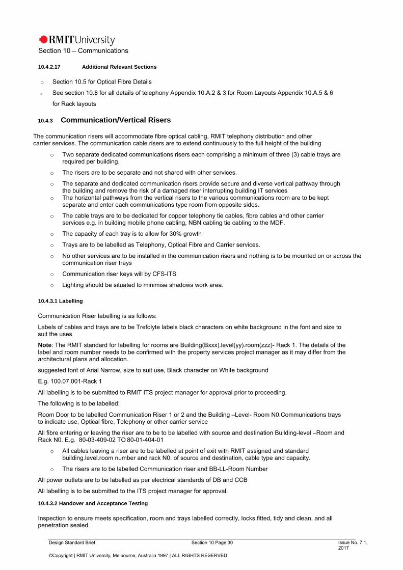
Design Standard Brief Section 10 Page 30 Issue No. 7.1, 2017
©Copyright | RMIT University, Melbourne, Australia 1997 | ALL RIGHTS RESERVED
Section 10 – Communications
10.4.2.17 Additional Relevant Sections
o Section 10.5 for Optical Fibre Details
o See section 10.8 for all details of telephony Appendix 10.A.2 & 3 for Room Layouts Appendix 10.A.5 & 6
for Rack layouts
10.4.3 Communication/Vertical Risers
The communication risers will accommodate fibre optical cabling, RMIT telephony distribution and other carrier services. The communication cable risers are to extend continuously to the full height of the building
o Two separate dedicated communications risers each comprising a minimum of three (3) cable trays are required per building.
o The risers are to be separate and not shared with other services.
o The separate and dedicated communication risers provide secure and diverse vertical pathway through the building and remove the risk of a damaged riser interrupting building IT services
o The horizontal pathways from the vertical risers to the various communications room are to be kept separate and enter each communications type room from opposite sides.
o The cable trays are to be dedicated for copper telephony tie cables, fibre cables and other carrier services e.g. in building mobile phone cabling, NBN cabling tie cabling to the MDF.
o The capacity of each tray is to allow for 30% growth
o Trays are to be labelled as Telephony, Optical Fibre and Carrier services.
o No other services are to be installed in the communication risers and nothing is to be mounted on or across the communication riser trays
o Communication riser keys will by CFS-ITS
o Lighting should be situated to minimise shadows work area.
10.4.3.1 Labelling
Communication Riser labelling is as follows:
Labels of cables and trays are to be Trefolyte labels black characters on white background in the font and size to suit the uses
Note: The RMIT standard for labelling for rooms are Building(Bxxx).level(yy).room(zzz)- Rack 1. The details of the label and room number needs to be confirmed with the property services project manager as it may differ from the architectural plans and allocation.
suggested font of Arial Narrow, size to suit use, Black character on White background
E.g. 100.07.001-Rack 1
All labelling is to be submitted to RMIT ITS project manager for approval prior to proceeding.
The following is to be labelled:
Room Door to be labelled Communication Riser 1 or 2 and the Building –Level- Room N0.Communications trays to indicate use, Optical fibre, Telephony or other carrier service
All fibre entering or leaving the riser are to be to be labelled with source and destination Building-level –Room and Rack N0. E.g. 80-03-409-02 TO 80-01-404-01
o All cables leaving a riser are to be labelled at point of exit with RMIT assigned and standard building.level.room number and rack N0. of source and destination, cable type and capacity.
o The risers are to be labelled Communication riser and BB-LL-Room Number
All power outlets are to be labelled as per electrical standards of DB and CCB
All labelling is to be submitted to the ITS project manager for approval.
10.4.3.2 Handover and Acceptance Testing
Inspection to ensure meets specification, room and trays labelled correctly, locks fitted, tidy and clean, and all penetration sealed.

Design Standard Brief Section 10 Page 31 Issue No. 7.1, 2017
©Copyright | RMIT University, Melbourne, Australia 1997 | ALL RIGHTS RESERVED
Section 10 – Communications
10.5 Optical Fibre Cabling
This section details the expected standards for optical fiber cabling for across the university.
o Two (2) x 24 core OS2 optical fibre cables will be installed to each location as a minimum. It is preferred where economically possible that the two cables are installed using diverse pathways both within and external to the building.
o Where this is not possible the two fibre cables to each location should be installed in separate conduits and risers.
10.5.1 Optical Fibre Cable Specifications
o Fibre cables shall meet the following transmission specifications: -
o OS2 Specification9/125 m Fibre
o Sheath colour (indoor) Yellow
o Maximum fibre attenuation:
0.4 dB/km at 1310 nm
0.4 dB/km at 1383
0.3 dB/km at 1550 nm
o Supported length for 1GBE - 5,000 m depending on design & application
o Supported length for 10GBE - 10,000 m depending on design & application
o Supported length for 40GBE - 10,000 m depending on design & application
o Supported length for 100GBE - 40,000 m depending on design & application
10.5.2 Optical Cabling Installation Standards
All cables shall be run and installed in accordance with AS/ACIF S009 Wiring Rules for safety and network integrity, and ISO/IEC 11801 for performance, and as per manufacturer’s requirements.
Termination of optical fibre cables shall be in rack mounted enclosures using LCA connectors unless otherwise specified.
The installer should ensure that cables shall be installed so as not to exceed the minimum bending radius. Bend Control accessories shall be used at any change of vertical direction by more than 45 degrees. All cabling is to be adequately supported as per manufacturer recommendations The installer is to ensure that all pathways conform to the recommendations in AS/NZS 3084 Pathways and Spaces and the cable manufactures requirements, Cable pathways are to have 30% spare capacity for future expansion. Cables that penetrate fire barriers shall have the penetrations suitably fire-stopped as specified in the RMIT fire standards.
Indoor installations must following the below standards for Optical fibre cable types and installations
o Indoor Tight Buffered OF Cable for all internal horizontal and riser use. Cables must not be subjected to
heat radiation, condensation, precipitation or formation of ice.
o LSZH (low smoke zero halogen) cables should be considered.
o Indoor conduits shall be installed in such a way that the indoor OF cable does not lie in trapped or ponded water/fluid/condensation inside the conduit.
Outdoor Above Ground Installations must following the below standards for Optical fibre cable types and installations
o Underground Loose-tube Gel-filled cable has a UV-resistant sheath and can be installed in outdoor
above ground applications.
o

Design Standard Brief Section 10 Page 32 Issue No. 7.1, 2017
©Copyright | RMIT University, Melbourne, Australia 1997 | ALL RIGHTS RESERVED
Section 10 – Communications
o Outdoor conduits above ground shall be self-draining so that the indoor tight buffered cable does not lie in trapped or ponded water/fluid/condensation inside the conduit.
o Note: Indoor Tight Buffered cable may be used for outdoor above-ground applications when installed in weather-proof self-draining UV-resistant conduit. Cables must not be subjected to heat radiation, condensation, precipitation or formation of ice.
Underground Installations must following the below standards for Optical fibre cable types and installations
o 9Underground Loose Tube Gel-filled OF cable is to be used for all underground applications. The cable
is not to be direct buried but to be buried in conduits.
o Underground Gel-filled OF cable must pass the “Water Penetration Test” as referenced in AS/CA S008. A UV- resistant sheath sacrificial sheath over the nylon jacket is preferred for underground loose-tube OF cable.
o Underground Loose Tube Gel-filled cable should be terminated within 15m after it enters a building and changed to an Indoor cable to meet AS/CAS009 flammability and minimise combustion risk. A suitable location is required possibly in each riser using a FIST enclosure.
o Underground cable must be suitably sealed where it enters and exits the ground against UV radiation and mechanical impact
10.5.3 Pre-Terminated Optical Fibers
RMIT University does not accept Pre-Terminated Optical Fibre (PTOF).
10.5.4 Colours For Optical Fibre Adaptors, Connectors and Cables
o Optical fibre adaptor colours and connector colours for 3 mm patch cords should be; OS2
9 m Green (APC – Angled Physical Contact at 8 degrees)
o The sheath colour for optical fibre patch cords shall be OS2 9 m Yellow
o All Pigtails are to be colour coded
10.5.5 Optical Fibre Link Testing
o The installer must individually test 100% of the optical fibre cables after installation of the cables to determine compliance to ISO/IEC 11801 performance requirements.
o All testing shall be conducted in accordance with the latest manufacturer testing requirements.
o All single mode optical fibre cores must be tested using a Fluke DTX series or equivalent;
Continuity and Maintenance of Polarity
o Length Propagation Delay
o Optical Attenuation of Link,2 x wavelengths, 2 x direction
The tests are to be conducted in accordance with ISO/IEC 14763-3 and the manufacturers Performance Testing of Optical Fibre Links for Compliance to ISO/IEC 11801, using Light Source and Power Meter (LSPM).
Tests are to be conducted in both directions and in the following wavelengths
Singlemode: 1310nm and 1550nm
9 Refer to Building Lead In, Pits, and Pipes Section 10.10 for more information

Design Standard Brief Section 10 Page 33 Issue No. 7.1, 2017
©Copyright | RMIT University, Melbourne, Australia 1997 | ALL RIGHTS RESERVED
Section 10 – Communications
Note: An OTDR is not acceptable for Link Loss measurements.
At both ends of the fibres provide Optical Time Domain Reflectometer (OTDR) graphical lot and cable length measurements for each fibre.
OTDR testing shall utilise a launch and a tail cable.
The tail shall be of such a length to show the loss of the last connector and prove continuity for OTDR testing.
Fibre optic results shall also be presented showing a summary of the loss results. Negative loss results for fibre will not be accepted.
All OTDR Traces saved shall be in Bellcore Format.
10.5.6 Test Results of Optical Fibre Testing
Provide an electronic copy of all tests in ASCII text format. Test results shall include the following items:
o Point to Point identification and direction of test; Wavelength;
o Test Method Used;
o Test equipment manufacture, model number, serial number, date of last calibration and stand to which it was calibrated;
o Date of Testing;
o Tester(s) name and qualifications. Cable records to be updated or include on site.
10.5.7 Fiber Optic Break Out Trays (FOBOT)
Rack mountable Fibre Optic Break out trays (FOBOT) are to be used for termination of the optical fibres.
o Enclosures shall be capable of supporting LCA Duplex optical fibre terminations.
o Enclosures should be sized to suit core termination count.
o The termination of single mode cables will be undertaken via a direct splicing onto colour coded LCA
pigtail. The single mode connectors (LCA) shall be installed into the required patch panel via an LC
duplex adaptor
10.5.8 Building Communication Room FOBOT
Building Communications room will require several high-density enclosures with capacity to suit a fibre count of all the potential communications rooms in the building.
o TE High density RTCG 3RU panel, 24 core angle Left /Right face pate to allow for multiple 24 cores of OS 2 to be terminated on LCA connectors from each floor communication room of the building
Refer to Appendix 10.A.12 for Building Communication FOBOT layout
10.5.9 Floor Communication Room FOBOT
Floor communication rooms will use the following:
o TE 1RU RTCG series, fitted with L/R face pate to allow the 2 X 24 cores of OS 2 to be terminated on LCA connectors
o TE Part No RTC1G-LCA-48-PO-A24-PO-Z-OS2
Refer to Appendix 10.A.13 for Floor Communication FOBOT layout
10.5.10 Fiber Splicing

Design Standard Brief Section 10 Page 34 Issue No. 7.1, 2017
©Copyright | RMIT University, Melbourne, Australia 1997 | ALL RIGHTS RESERVED
Section 10 – Communications
Joining of cables is not permitted except on optic fibre cabling where terminations have pigtails that need to be spliced to the installed cables.
Suitable trained individuals utilizing state of the art precision fibre splicing equipment shall perform all splicing.
In a limited number of locations where splicing pits have been approved and are established,
o splicing using Tyco FIST GC02 type enclosure is allowed.
o In these specific locations RMIT ITS network team will allocate the splice trays and cores to be spliced to a new cable.
10.5.11 Optical Fibre Patch Cords
The optical fibre patch cords must match the core size of the fibre used on the patch panels and network equipment.
o Fibre Patch Cords shall be Duplex, singlemode LCA, 9-micron core with 125 microns cladding to suit the installed OS2 fibre optic cabling. To be used for cross connects and interconnects
The following specifications shall be met.:-
o Minimum bend radius: 25 mm
o Operating temperature: -40 to +75º C
o Loss: 0.75 dB per mated pair of connectors
o Return Loss Maximum: -45dB
o Cable OD: 3 mm
o Tip material: Ceramic
o The fibre cladding is to be covered by Kevlar fibres and a protective outer jacket.
Quantity and length required are to be advised once the number of outlets are known which will determine the switch capacity to be provided.
For costing purposes, the following quantities of fibre patch leads can be used per Floor Communications room
parts 10 X 2m OS-2 LCA –LCA e.g. TE Part No 6881 1 488-3020YL
10 X 3m OS-2 LCA – LCA e.g. TE Part No 6881 1 488-3030YL
Final quantities will be confirmed as part of the project
10.5.12 Labelling of FOBOT
All cables entering and/or leaving buildings, riser or terminations enclosure (FOBOT) shall follow the following standards:
o Fitted with a durable label indicating including cable type, unique cable identifier, total number of cores and source and destination buildings and the riser.
o Each cable at each pit location will be denoted with a source and destination label. Labels shall be engraved on stainless steel tags with type, size and fixing being approved by the ITS Property Services Project Manager.
o “Brother U and “Dymo” type labels shall only be used as an interim label; Hand written labels are not permitted even in the interim. Permanent labelling shall be of the “Brady” metallised polyester type, Trefolyte or approved equivalent.
o All FOBOT at the front for each fibre to be labelled:
o fibre type, fibre cores and destination Building-level –Room and Rack N0.
o E.g. 24 Core OS-2 80-03-409-02 TO 80-01-404-01
o Fibre cables at the rear are to be labelled with
o Fibre Type and size and the destination Building-Level–Room and Rack N0.
All labelling is to be submitted for the approval of the RMIT ITS project manager prior to installing

Design Standard Brief Section 10 Page 35 Issue No. 7.1, 2017
©Copyright | RMIT University, Melbourne, Australia 1997 | ALL RIGHTS RESERVED
Section 10 – Communications
10.5.13 As Built Documentation & Acceptance Testing
o As built showing all cable pathways,
o A schematic diagram of fibre optic cabling installation.
o Cable manufacturer’s warranty
o A pdf of the test result for all cables including lengths is to be available for RMIT ITS representative
to review. Inspection of the installation by ITS representatives.
10.6 Unshielded Twisted Pair (UTP) Cabling This section details the expected standards for Unshielded twisted pair cabling for across the university
o RMIT requires a Category 6A structured cabling solution for data and communications. The system will be
installed to Class EA standards 500 MHz
o The Structured Cabling Solution will comprise Category 6A components capable of providing 10 Gigabit Ethernet
operations using full duplex transmission.
10.6.1 UTP Cable Specifications
o Cable Type is to be TE four pair Category 6A. RMITs preferred colour is grey but if it is not readily available Blue is acceptable. Part No TE640R-GYM2 (GREY), TE640R-BLM2 (BLUE)
o Grey is used to distinguish newer installation Category 6 and Category 6A from the legacy blue cables used at RMIT for Category 5 and Category 5e.
o Cable Standard is to be to AS/NZS 3080 and AS/CA S008
o Installations requiring a reduction in PVC materials can use the low smoke zero halogen (LSZH) cabling
10.6.2 UTP Cable Terminations
o All UTP cable terminations shall use the insulation displacement contact (IDC) method
o All RJ45 outlets, patch leads, fly leads, system tails shall be terminated using the EIA preferred sequence as per A.S. 3080, T568A.
10.6.3 Copper System Tails / Patch/ Fly Leads
o All patch leads, fly leads (1 per outlet) and system tails (1 per outlet) are to be supplied.
o Patch cables shall be capable of the highest operating transmission rates as per AS/NZS 3080
class EA. TE Category 6A fly leads are to be required to be supplied.
A fly lead is required for every outlet installed. The leads are required in a combination of 3m, 2.1 and 1.2 metre for the work area. The length and quantity of each will need to be confirmed with the ITS project manager as it depends on outlet location at the desk and other devices.
10.6.4 Outlet Type
o All outlets supplied shall be TE Category 6A modular 8P8C fixed connector outlets, accepting standard
modular RJ45 free connector plugs Part No 6467 4 272-00
o Made from high-impact, flame-retardant, UL94 -V0 rated thermoplastic material or shielded metal
Meet or exceed AS/NZS 3080 and ISO/IEC 11801 Category 6A, component requirements
o RMIT approved type – TE Krone Flush mount Colour- White on white faceplate

Design Standard Brief Section 10 Page 36 Issue No. 7.1, 2017
©Copyright | RMIT University, Melbourne, Australia 1997 | ALL RIGHTS RESERVED
Section 10 – Communications
10.6.5 Mounting
o Flush mount or surface mount to suit location at desk, wall etc.
o Outlets should be above the desk height where possible and located in the centre of the desk area to from the need for long fly leads and to accommodate left or right-hand people.
o The rear of the outlet and cabling should be protected from disturbance. Open back outlets with no covering under desks etc. will not be accepted.
o Surface mount kits are to be used in wall behind IP clocks and in false ceiling where outlets are used for wireless access point
10.6.6 UTP Cable Installations
o All 4-pair cabling shall be run using a star topology format from the cross connect at the floor
distributor (FD) on each floor to every individual telecommunication outlet on that floor.
o Each run of cable from the cross connect at the floor distributor (FD) to the telecommunication outlet (TO) shall be continuous without any joints or splices. Consolidation points (CP) are not permitted by RMIT.
o The length of each cable from the floor distributor (FD) to the telecommunication outlet (TO) shall be based on the distance set out in the tables and formulas in ISO/IEC 11801 plus the appropriate length de-rating for ambient temperatures above 20ºC. Installed lengths may differ from the designed lengths if they pass testing and do not exceed 90m in length.
o The 4-pair UTP cable should be Underwriter Laboratories (UL) listed as type CM or CMR; or be nominated as LSZH to IEC 60332-1.
o All data and telecommunications cables are to be run on their own dedicated cable pathways.
o Cables trays of sufficient design and side height, Bundles of correct size and installation method are used,
o Separation of fixed telecommunications cabling and parallel runs length of LV fixed electrical cabling
o Correct bend radius is maintained throughout – minimum of 50mm Radius Maximum hauling tension
not exceeded
o Cables are secured using Velcro only. Cable ties are not acceptable
10.6.7 Testing of UTP Cabling
o The installer must individually test 100% of the copper cables
o The Structured Cabling System shall be tested by the installer for compliance to the requirements specified in the latest ISO/IEC 11801 standard for Class EA, F or FA performance using at least Level 3 testers or better in accordance with AS/NZS IEC 61935.1 – Testing.
o The design data and the full results of all compliance tests performed by the installer are to be fully documented
o The results must include 100% of total installation and provide full electronic data files for each cable run indicating the name of the person doing the testing, date, building, cable identification, cable length, and all the parameters specified in ISO/IEC 11801. TE will not accept permanent link cable lengths greater than 90 metres into their warranty program.
o Cables that fail or *fail will not be accepted.
o Cables where the length is >90metres will not be accepted by RMIT. This length is to ensure sufficient overhead for the addition of system tail, cross connect and work area patch lead up to 3m and remain under 100m.
o Alien Crosstalk (AXT) testing is not required on TE Category 6A, installations; therefore, no AXT sampling plan is necessary.

Design Standard Brief Section 10 Page 37 Issue No. 7.1, 2017
©Copyright | RMIT University, Melbourne, Australia 1997 | ALL RIGHTS RESERVED
Section 10 – Communications
10.6.8 Installer
o The contractor shall be trained and certified to install the vendor products system and must offer a single 25-year extended warranty on the entire structured cabling system installation.
o The entire scope of works shall be performed by a single contractor - No sub-contractors are to be used.
10.6.9 Labelling
Field Outlet labelling is to be used an as per standards below:
o Building Number.level Number. room of the floor communications room, followed by the outlet number starting at 001 and increasing clockwise around the floor.
o This numbering assists with locations that are on building boundaries, originate in two story lecture theatres and other outdoor locations where it is difficult to know where an outlet originates from. Contractor to suggest options
o Frame outlet labelling is to be the same as the field outlet.
o Subject to space on the label it would be advantageous if the level and room that the outlet resides in could also be added.
o System cabling labelling is to be switch name and port number. RMIT will advise the required label that will be fitted at both ends.
10.6.10 Acceptance Testing and Handover
o A certain percentage of the outlets may be chosen by the customer at random for verification of
compliance testing.
o The installation will be checked against the ITS communication room check list and the floor
check list. A pdf of the test result for all cables including lengths is to be available for the
customer to review.
o The completed patch record folder will be inspected as part of the review
10.6.11 Documentation
o Plan of all cable pathways and as built floor plan showing outlet location and all outlet numbers
o A pdf of the test result for all cables including lengths is to be available for RMIT ITS representative to
review. Field outlet frame diagram and
o All records completed at both sides of jumper
o Warranty
10.6.12 Telecommunication Outlets requirements
All outlets are to be positioned to allow the correct bending radius of the fly lead out of the outlet.
Exact quantities of outlets required are to be confirmed with RMIT client, but the following is a minimum requirement:
o Staff Work Stations-1 per workstation in the middle of the desk area Note specialist areas may require
additional
o Reception desks will require additional outlets
o MFD (Printers and faxes) locations require a minimum of 2 outlets per device Wireless Access point Two (2)
per Access point location
o Ceiling Projectors one outlet per projector

Design Standard Brief Section 10 Page 38 Issue No. 7.1, 2017
©Copyright | RMIT University, Melbourne, Australia 1997 | ALL RIGHTS RESERVED
Section 10 – Communications
o Security Challenger door controller – 2 per location CCTV camera 2 per location
o Fire panel – 2 outlets
o Building Automation System (BAS) as per solution requirements
Minimum of 2 outlets per location but more may be required depending on the number of devices. One for device and other for technician
o Lighting control 1 outlet minimum
o Emergency lighting controller – 2 outlets 1 outlet for device and 1 for technician Student Lab workstation
o per PC but one additional per work station cluster for printers etc. Meeting rooms -large
o Four (4) outlets in the middle of the meeting table, IP telephone, Analogue conference phone, AMX touch panel and one for presenter laptop
o AV rack will require up to 8 – AV to confirm requirements 1 for projector if installed
o If wall mounted displays – 2 outlets – above display to allow bend radius of fly lead out of outlet Meeting room
–Medium 8 people
o As per large meeting room Meeting room- Small
o Two on each side of meeting room
o Wall mounted displays with or without in built PC as follows:
o outlets per display located slightly above the top of the mounted screen height – position to ensure that patch lead at outlet and unit can be fitted and maintain the correct bend radius for Cat6A
o AV racks – 8 outlets as follows
o Lectern- 2 On top for IP telephone and laptop and 6 underneath in AV rack
10.7 Telephony Systems
The University has an Avaya Cs1K VOIP telephone system. The system supports both VOIP handsets and analogue services e.g. faxes and other analogue handsets
o A 24-port cat 3 panel is to be installed to cater for non-IP based telephony in the racks.
o Must be placed in the second rack panel
o Cables are run from the Building distribution room or where the MDF is located
10.7.1 Telephone handsets
The University uses Avaya 1140e VOIP handsets and Interquartz analogue handsets
o The Consultant shall confirm the allocation of all telephone handsets and types with the Project
Manager. All handsets shall be purchased by the project
o Approval is required for cost of each item including allowances for the purchase of handsets, programming of extensions and handset configuration by ITS telephony staff, for project budget purposes.
o VOIP Handsets are required at all locked door entrances and at all lecterns. An analogue handset is fitted
in front of all fax machines to provide a power fail handset in the unlikely event the data network is interrupted.
o The analogue handset is to be fitted with an RMIT label advising that the phone is for power fail and is not to be disconnected
10.8 Analogue Telephone Distribution Cabling
10.8.1 Analogue Telephone Cabling
All cabling work on the University network shall be carried out by a registered cabler with appropriate endorsements. All such work shall meet the minimum requirements of the current standards and comply with all

Design Standard Brief Section 10 Page 39 Issue No. 7.1, 2017
©Copyright | RMIT University, Melbourne, Australia 1997 | ALL RIGHTS RESERVED
Section 10 – Communications
regulations. Installation shall be in accordance with the following criteria.
o Include Communications Earthing System (CES) conductors, the CET blocks and all earthing conductors up to the protective earthing point of all rack and frames.
o Underground service cables shall be specified as 1/0.40mm2 jelly filled underground telephone cable.
o Internal telephone block cabling shall generally be specified as indoor grade 1/0. 50mm2 standard telephone cable (Cat3).
o Cable between Campus Distribution locations (MDFs) and Building distribution room and the same to the Floor distribution located in the floor Communications room shall provide 50% spare capacity.
o Telephony will use the Cat6 A outlets as part of the structured cabling solution; All cable terminations shall
use the insulation displacement contact (IDC) method
o Multi-pair tie cables between building MDFs shall terminate onto standard Krone “white” “Profile” LSA Plus disconnection modules and mounting system catering for up to 10 pairs each labelled 1-10 only.
o All pairs of all cable shall be tested
o Outlets for Analogue services are to be part of the Cat6A structured cabling solution. 100 pair Designation
strips are to be fitted and labelled
10.8.2 Inter Building and Internal MDF Cabling
o Inter building cables from both the central MDF (for VOIP analogue services) and from a local MDF (if applicable) shall be 50 pairs of Category 3 cabling.
o Wherever possible it is required that 2 X 25 pair Category 3 cables are run using diverse cable pathways and diverse risers to increase the survivability in the unlikely event that a riser is damaged.
o The cabling is to terminate on IDC displacement at both the source and destination. Modules will be as outlined in 10.8
o The cables will terminate as per Appendix 10.A.8 on Vertical A of the telephony frame located in the building Communications room
o The cables from the Building MDF will terminate on Vertical A pairs 1-50 in the Building Communication room
o The cable(s) from a RMIT MDF used to deliver PABX analogue circuits will terminate to the allocated building communications room. Please engage ITS for this location.
10.8.3 Intra Building Cabling
o A 20-pair category 3 telephony tie cabling from the Building communications room wall mounted distribution frame (Refer Appendix 10.A.8) are to be terminated patch panels on the racks.
o Wherever possible it is required that 2 X 10 pair Category 3 cables are to be installed diverse cable pathways and diverse risers.
10.8.4 Retail Tenancy
This section defines the standards if a retail tenant is to have their required services from their preferred carrier delivered
o A 10-pair cable from the building MDF to each retail tenancy is required.
o This is required for the retail to have their required services from their preferred carrier delivered.
o A 10-pair category 3 cable from each tenancy is required to the Building Communication Room IDF. These cables will be terminated on Vertical A using 10 pair disconnection modules in the location indicated in Appendix 10.A.8
This is required should RMIT services need to be delivered to the spaces
10.8.5 Testing of Telephony Cables

Design Standard Brief Section 10 Page 40 Issue No. 7.1, 2017
©Copyright | RMIT University, Melbourne, Australia 1997 | ALL RIGHTS RESERVED
Section 10 – Communications
Testing of all Category 3 cables must include:
o Cable route length
o Continuity
o Correct sequence
o Reversed pairs
o Transpositions and split pairs
10.8.6 Telephone Distribution Frame Records
o A record book is to be supplied and completed in pencil and is to be clear and legible at all telephony frames.
o The record book is to record all pairs cross connected.
o Records are to be cross matched at both ends of the jumper and include the respective service number
o The records are to include details of the following
o tie cabling, frame location, cable size, location of destination Building, Level, Room number and vertical and cable pairs at the destination end
o A suitable holder for the records is to be provided at each frame location.
o The record book is to of a size that can accommodate the records of the entire back mount capacity
10.8.7 Labelling
All tie cabling is to be labelled with the following o Source and destination room, cable type and pair number and which of the two cable risers is used, where
the cable leaves the rooms, exits risers, in all pits and at entry and exit of all buildings.
Frame labelling is to include
o 10 counters at the end of each module Vertical are to be labelled - Vertical A, B etc.
o designation modules are to be fitted and labelled after each 100 pairs, Labelled with vertical and pairs o e.g. Vert A, 1-100
10.8.8 Documentation for retail tenancy
o The contractor shall provide all records folders at each frame and complete all records in pencil and is to be legible.
o The documentation is to include a schematic diagram of the category 3 cabling showing all cable type, size, (pairs), room of all terminations and risers
o A cable pathway floor plan is required for all cabling.
10.8.9 Permitted Attachments
o All equipment intended to be attached to the University telephone system shall be of an ACMA approved type and be fitted with a label displaying the relevant ACMA permit number.
o Data modems shall not be connected to the University telephone system, without permission from ITS.
o FAX machines shall be connected to the RMIT VOIP Telephone Network. The connection of FAX machines via direct exchange line is to be avoiding where possible
10.8.10 Handover
ITS will inspect the cabling, termination locations, documentation and test records as part of handover.
10.9 Building Distribution Frame (BD)

Design Standard Brief Section 10 Page 41 Issue No. 7.1, 2017
©Copyright | RMIT University, Melbourne, Australia 1997 | ALL RIGHTS RESERVED
Section 10 – Communications
10.9.1 New Buildings
The consultant is to liaise with RMIT carriers and specify a Building Distribution (BD) of suitable size, conduit access, and power to accommodate at least the following:
o In accordance with appropriate standards including AS/NZS 3084 Multiple Carrier incoming copper and fibre
optic cables
o Multiple Carrier racks for in building for mobile coverage, IP WAN services, and future NBN or similar.
o All cable terminations shall use the insulation displacement contact (IDC) method
o Two walls mounted TE 500 way Profile back mount and rod is to be provided and installed on a 20mm back
mount
o A space of 300mm at each end for shoulder room.
o All Category 3 cabling is to be terminated on TE 10 pair (1-10 labelled) disconnect modules. 100 pair
designation labels are to be used.
o A record folder, completed in pencil is to be clear and legible, is to be provided and a suitable wall mounting point.
o The Building Main Distribution Frame is to have 50pairs of Cat3 copper and 24 cores OS-2 fibre tie cabling to the RMIT building communications room to allow interconnection to RMIT infrastructure if required.
o At least 4 x 15amp captive (Clipsal style) power outlets are required along with 2 x 10amp for miscellaneous use.
o Supply and installation of all Communications Earthing System (CES) conductors, the CET blocks and all earthing conductors up to the protective earthing point of all rack and frames.
10.9.2 Testing
Testing of cables must include:
o Cable route length
o Continuity
o Pin Assignments
o Correct sequence
o Reversed pairs
o Transpositions and split pairs
10.9.3 Existing Campus MDF for RMIT PABX Connection
The provisioning of new Building communications room requires a tie cable to an existing campus MDF. ITS networks team to determine the most suitable site for connectivity.
10.9.4 Documentation
A record folder, completed in pencil is to be clear and legible, is to be provided and a suitable wall mounting point.
A copy of all test results.
10.9.5 Handover
Handover will require test results and an inspection of the records and the installation.

Design Standard Brief Section 10 Page 42 Issue No. 7.1, 2017
©Copyright | RMIT University, Melbourne, Australia 1997 | ALL RIGHTS RESERVED
Section 10 – Communications
10.10 Building Lead In, Pits, Pipes
10.10.1 Conduits
o There is to be a minimum of 2 x 100mm communication conduits in each of the two building lead-in pathways dedicated to RMIT ITS infrastructure. Additional conduits may be required for other services, e.g. fire cables etc.
o The two lead-in pathways are recommended to be geographically separate conduit paths (each of 2 conduits) to increase the redundancy of a buildings connection in the unlikely event that conduits are damaged.
o Other conduits from telecommunication carriers and other education carriers may also be required.
Minimum Depth of conduit 300mm
o All removed fill is to be discarded and new backfill is to be used
o Tape over conduits half the depth of advising of conduits below is to be installed
o The conduits are to be labelled at point of entry as communication conduits use only.
o Conduits entering buildings shall be sealed using products like the Rayflate Duct Sealing System (RDSS)
10.10.2 Conduits Spacers
o Where a conduit infrastructure is intended to service multiple buildings now and progressively in the
future, then use of Maxicell fabric liners from Tyco is to be used.
o This eliminates the loss of space due to cables twisting around each other, and allow for the removal of redundant cabling and ease of adding additional cabling.
o The use of the 6 bags per 100 mm conduit is required. The product is available by the km only and will be used for significant conduit installations
o Installation is to be as per manufacturers recommendations.
10.10.3 Pits
In ground pit, should be of suitable construction for that locality with the following standards o an allowance to cater for at least four (4) dual 100mm conduits from 2 sides only (i.e., a total of eight x
100mm conduits).
o The pit should have a suitable lockable cover of metal construction
o All Conduit entry points into a pit need to be sealed using products like the Rayflate Duct Sealing System (RDSS).
o Large radius bends shall only be used
o Pit lids are to be metal and to be of suitable classification for cars etc. Gatic lids are acceptable.
o If pits covers are required to have additional covering for aesthetics that increases the weight, a suitable mechanical lifter is to be provided to allow easy and safe handling access to the pits.
o Pits shall be installed on suitable material to provide drainage.
o Cable runs are to be continuous and without joints unless approved by ITS Property Services Project Manager
o Long conduit runs are to have a pit at suitable location to allow the easy installation of additional cabling in the future. Between pits the total angle of all bends is not to exceed 180degrees.
10.10.4 Fibre Jointing Pits
o Nominated fibre jointing pits are to be of a suitable size to allow cable coils to allow joint to be removed for future
terminations
o Tyco FISTGC02-xx joint of suitable capacity is to be used. A suitable hanger is required in the pit

Design Standard Brief Section 10 Page 43 Issue No. 7.1, 2017
©Copyright | RMIT University, Melbourne, Australia 1997 | ALL RIGHTS RESERVED
Section 10 – Communications
o Large pits are to have suitable catenary wires to allow cables to be held off the bottom of the pit keeping them pout of the water and mud
o Copper cabling is not to be jointed in pits unless approved by ITS representative. If approved a Tyco or similar copper joint kit is to be approved by RMIT prior to proceeding.
10.10.5 Cable Testing
All testing is to be as per
Fibre testing is as per section 10.5
Copper telephony testing is as per 10.8
10.10.6 Labelling
o Labelling of cables in every pit is to include source and destination in the format (Building N0.-Level N0.- Room number) as per RMIT room number schema., cable type, cable size, cable riser number.
o Labels shall be engraved on stainless steel tags with type, size and fixing being approved by ITS.
o Pit shall be clearly labelled RMIT COMMUNICATIONS
10.10.7 Documentation
Documentation is as per section 10.5,10.8
Plus, an accurate map suitable for loading into Property Services tools showing the following:
o conduit pathways
o depths of all conduits and pits
o pit sizes, location including GPS co-ordinates of all pits number of conduits including conduit layouts
o Jointing pits are to indicate joint type and capacity
All new conduit work shall be documented in a form suitable for registration with Dial before you dig.
Design Standard Brief Section 10 Page 44 Issue No. 7.1, 2017
©Copyright | RMIT University, Melbourne, Australia 1997 | ALL RIGHTS RESERVED
Section 10 – Communications
10.10.8 Handover
Handover will include an inspection of the following:
o Documentation
o Cabling test results
o As built drawings etc.
o Physical inspection of a random number of pits and cable runs
10.11 Power at Desks.
o A minimum of 2 double GPO is required at staff desks.
o Ideally power is above desk to avoid crawling under to plug in devices and laptops.
o Note: Power points to have enough spacing to all surroundings to allow for large power adaptor packs to be connected without the need for alternative cables or adaptors.
o Note: all switches are capable of POE capable.
10.12 Wireless Access Points
As RMIT has an established wireless network solution, ITS will be providing wireless access to sites where required. The following standards are listed below:
RMIT recommends the use of HPE wireless planning guide as a rough guide to assist in the basic wireless access point quantity required as part of a fit out for a per type of area.
The location and mounting of WAP is to be in line with specifications of RMIT recommended vendor recommendation for installation.
o Mounted below the ceiling and at least 1 metre from any light or metal. o Horizontal and parallel to the floor unless approved and signed off by RMIT ITS representative
o The RMIT supplied WAPs are to be mounted by the contractor and the UTP patch leads is to be
connected as instructed by RMIT network staff o Dual cabling is required for the WAPs when connected to the switch
o The contractor is to record the details of each WAP label, the location installed and the outlet it is
connected to. The WAP is to be plugged into the outlet with the lowest number.
10.13 Physical Server Applications
The design of the solution will be subject to RMIT ITS review and advice ITS will provide all Physical servers and operating systems for all systems at the cost to the project.
The vendor will need to provide an architecture overview of the solution that includes but is not limited to the following:
o Application hardware specifications o Operating system options, o Configuration, o Security hardening, o Account management and o Integration
10.14 IP Address Allocation for Devices
All IP addressing will be allocated by the ITS networking team for devices, servers etc. The contractor is to complete and submit the form embedded to the ITS project manager. IP Addresses will only be allocated after the solution design is approved by RMIT ITS.

Design Standard Brief Section 10 Page 45 Issue No. 7.1, 2017
©Copyright | RMIT University, Melbourne, Australia 1997 | ALL RIGHTS RESERVED
Section 10 – Communications
This is to be used for o Security access control devices o CCTV o Audio visual systems o BMS system and controllers o Lightning interfaces o Emergency lighting controller o IP clocks etc.
Any other system or device requiring IP address and network connectivity are subject to the above process.
10.15 Tenant Locations
10-pair category 3 cable from the building MDF or central MDF is applicable is to be installed.
This will be terminated on a IDC displacement using patch panel .
Horizontal UTP outlets from the floor communication room are also to be installed to this.
The final fit out of a tenancy will need to accommodate the respective carriers equipment. At that time the cabling can be extended to the required location within the tenancy.
10.16 Hand Over at Project Completion
10.16.1 Handover
Project completion is required to comply with all hand over specifications of each section above relevant to what works was completed. The following requirements are expected to be conducted:
o Prior to hand over of the completed installation, approved as-built drawings shall be submitted.
o All Drawings shall be completed on approved Property Services drawing system of the day.
o The format and system type is to be confirmed with Property Services.
o Soft copy of manual along with a hard copy of the Manuals is to be supplied to RMIT ITS
o Including: all original equipment with the cable specifications, all test results, testing parameters, loss budgets, light source power meter loss, OTDR test results, cable schematics, cable routes, pit locations, building names, patching details adaptor configurations and relevant descriptions of general system operation.
o Any documentation of exemptions to standards and subsequent approvals.
o The contractor shall provide complete documentation covering the installation and maintenance of the Structured Cabling System.
o Documentation of locations of all installed equipment and racks in all Communications Rooms, All main cable runs, cable trays, catenaries and conduits, pits, risers,
o Rack layouts
o Documentation of floor plans showing the location of all TOs, complete with outlet numbering
o Documentation of schematic cabling diagrams are to be in a suitable holder within the building communications room and building MDF
o Documentation of as built floor drawing is to be in a suitable holder in each floor communication room.
10.16.2 Certification and Guarantee
The complete structured cabling system shall be certified by personnel trained and authorised by the cable and connector manufacturer (TE Krone) and a formal certificate detailing the certification results shall be provided to RMIT Property Services.
The contractor shall be an TE Krone ND&I certified to carry out 25-year warranty installations.
The contractor shall be trained and certified to install the vendor products system and must offer a single 25-year extended warranty on the entire structured cabling system installation.
Design Standard Brief Section 10 Page 46 Issue No. 7.1, 2017
©Copyright | RMIT University, Melbourne, Australia 1997 | ALL RIGHTS RESERVED
Section 10 – Communications
On completion of the certification phase the installed system shall be guaranteed to perform to the manufacturer’s specification for a period of no less than twenty (20) years. Full details of the performance standards shall be included with the as-installed documentation.
A manufacturer guarantee and certificate for application performance for the full system is required.
The 25-year application assurance shall cover the failure of the offered cabling system to operate the applications that the system was initially designed to support, i.e. those identified in the current (at the time of tendering) versions of the Cabling Performance Specifications (that is the AS/NZS 3080, ISO 11801 or TIA/EIA 568-B.2-1).
Provision of Training
Prior to Practical Completion, the Contractor and Specialist Sub-contractors shall provide the services of competent personnel to instruct the appropriate University personnel in the operation and maintenance of the installed systems.
10.17 Minor Augmentation or Partial Renovation < 20% Of Existing Floor Area
10.17.1 Overview
Minor works to add additional cabling to existing floors including minor renovations are to meet the minimum standards set out below:
o The minimum standard for all augmentations is a structured cabling solution comprising of TE Category 6
structured cabling solution using Krone angled 24 port patch panels
o TE Category 3 patch panel
o All mounted in MFB Rack custom part number R3462 as per RMIT Category 6 Rack layout.
o A maximum of 192 outlets are to be installed on patch panels per rack
o A suitable sized communications room as per specifications outlined in Section 10.4.2 Floor Communications Room is required
o Renovating a floor in multiple small works does not remove the need for the complete floor meeting Section 10.1 to 10.15 inclusive
o A renovated Building Communications room is to be as per section 10.4.1 New Building risers are to be
as per section 10.4.3
10.17.2 Floor Communication Room
o Shall be dedicated to communications cabling and data equipment only.
o If a new room is required to be built or the existing expanded, the floor communications room sizing and layout shall be of the sizing outlined in Appendix 10.A.2 or 3
o The minimum rack to be used for category 6 cabling
o Rack to be 45RU 800mm(W) x 900mm(D) equipment racks. RMIT specifies that the rack be MFB Series cabinet RMIT custom Part Number R3462
o Each data rack is to support no more that 192 TO data termination, if the installation is greater, than an additional data rack(s) will be required.
o LAN switches and routers are provided and installed by RMIT or their representative.
o ADC Krone UTP Cat 6 Angled Patch Panels;
o ADC Krone Optical fibre termination cabinet/panel as per Section 10.5. ADC Krone Patch Panel 25 port
voice 1RU slide out frame p/n as per section
o Rack mount UPS, APC 5000XLI with 2 battery packs if no central building UPS for communications rooms is to be provided.
Krone patch and fly leads are required for all outlets. Length to be approved by RMIT ITS project manager prior to proceeding.

Design Standard Brief Section 10 Page 47 Issue No. 7.1, 2017
©Copyright | RMIT University, Melbourne, Australia 1997 | ALL RIGHTS RESERVED
Section 10 – Communications
10.17.2.1 Power
As per 10.3.3.5 and 10.3.3.6
10.17.2.2 Cooling
As per 10.3.3.4
10.17.3 Telecommunication Outlet (TO) Identification
The existing numbering scheme is to be expanded. The University has an established system for allocating point numbers. The Project Architect shall consult the Project Manager before allocating point numbers, and shall ensure that the University system is followed from the developed sketch plan stage.
o Room/Points are to be numbered in a clockwise direction commencing at the major point of entry to a floor or area, working around the perimeter of the floor or area about the central corridor.
o On the face plate a unique number indicating the point number as follows: 001, 002 etc. The existing numbering is to be continued sequentially form the last number used.
10.17.4 Conformity to Standard
The latest versions of the following standards are to be complied with unless otherwise specified:
o AS/NZS 4117 Surge Protective Devices for Telecommunication Applications
o AS/NZS IEC 61935.1 (Replaces AS/NZS 3087) Testing of Balanced Communications Cabling in
Accordance with ISO/IEC 11801 – Part 1 ISO 11801 Ed 2(Alternate reference only) Information
Technology – Generic Cabling for Customer Premises
o TIA/EIA 568-B.2-1(Alternate reference only) Transmission Performance Specification for 4 Pair 100
Ohm Category 6 Cabling
o TIA 568-B.2-10(Draft 10GBE reference document) Information Technology – Augmented Category 6
Cabling
The following separation of services shall be maintained throughout the installation. o Separation of power and data cables at intersecting points shall not be less than 260mm, unless
suitable shields/filters are approved by the University.
o Separation of power and data cable when laid in parallel shall not be less than 600mm, unless
suitable shields/filters are approved by the University.
o All EM sources shall be identified and suitable clearances defined for UTP cable depending on
individual EM field strengths. At least 1m when running almost co-linear to common EM sources
(e.g. fluorescent sources).
o All high magnetic sources shall be identified and suitable clearances defined for UTP cabling
depending on individual field strengths.
o All Category 6 UTP cables, and applications, shall comply with FCC commercial regulations in
respect to EM radiations. Any equipment of unusual sensitivity to EM radiation should be identified
and avoided to prevent interference from the cable plant to the equipment. Such equipment, or
areas, should they exist, may require suitable filtering and conditioning procedures to provide EM
isolation.

Design Standard Brief Section 10 Page 48 Issue No. 7.1, 2017
©Copyright | RMIT University, Melbourne, Australia 1997 | ALL RIGHTS RESERVED
Section 10 – Communications
10.17.4.1 Telephony Systems
Telephone Handsets as per section 10.7
10.17.4.2 Analogue Telephone Cabling
As per section 10.8
o With the exception that the cables are terminated on a 25 pair TE 1RU Category 3 patch panel in the rack location specified.
10.17.4.3 Permitted Attachments
o All equipment intended to be attached to the University telephone system shall be of an ACMA approved
type and be fitted with a label displaying the relevant ACMA permit number.
o Data modems shall not be connected to the University telephone system, without permission from ITS.
o Where practical, departmental FAX machines shall be connected to the PABX Telephone Network. The connection of FAX machines via direct exchange line is to be avoiding where possible.
10.17.4.4 Testing
Testing to be as outlined in 10.8
10.17.4.5 Documentation
As outlined in 10.8
10.17.5 Category 6 Unshielded Twisted Pair (UTP) Cabling
10.17.5.1 UTP Installations
All UTP cables shall be ADC KRONE Category 6 horizontal 4 pair solid cable to connect each telecommunication outlet (TO) to the floor distributor in the communications rack.
o The type of horizontal cables used shall be 4-pair 100 high performance unshielded twisted pair (UTP) cable for Cat 6 applications.
o The UTP cable shall be of nominal 0.5 mm diameter bare solid copper conductors insulated with high-density insulation and a PVC sheath. The insulated conductors shall be twisted into pairs, with pairs balanced for maximum performance and noise reduction.
o The 4-pair UTP cable shall be run using a star topology format from the cross connect at the floor distributor (FD) on each floor to every individual telecommunication outlet.
o The 4-pair UTP cable must exceed AS/NZS 3080:2003 Category 6 requirements. It must be tested to Class E to ensure performance for any application up to and including 1000 Mbps from the floor distributor (FD) to the telecommunications outlet (TO) at the work area.
o All horizontal UTP cable must meet requirement specified for current applications such as IEEE 802.3, 10/100/1000 BASE T; IEEE 802.5, 4/16/100Mbps;
o Each run of cable from the patch panel in the communications rack to an outlet (TO) shall be continuous without any joints.
o The length of everyone run of fixed horizontal cable from the floor distributor in the communications rack shall not exceed 90 Metres to the telecommunication outlet (TO) shall be based on the distance set out in the tables and formulas in AS/NZS 3080:2003 plus the appropriate length de-rating for maximum ambient temperatures above 20ºC. Installed lengths may differ from the designed lengths if they pass testing.
o The 4-pair UTP cable should be Underwriter Laboratories (UL) listed as type CM or
CMR. The UTP shall be grey in colour to distinguish it from legacy Category 5 and
5e cabling

Design Standard Brief Section 10 Page 49 Issue No. 7.1, 2017
©Copyright | RMIT University, Melbourne, Australia 1997 | ALL RIGHTS RESERVED
Section 10 – Communications
o The 4-pair UTP cable shall meet or exceed the following AS/NZS 3080:2003 requirements specifications
for cable;
o Conductor DC Resistance (Max): 9.38 Ω/100m @ 20°C DC Resistance Unbalance (Max) 5%
o Insulation Resistance (Min): 5000 M /1km @ 20°C
o Mutual Capacitance (Typical): 5.6 nF/100m
o Characteristics impedance: 100 Worst Case Cable Skew: 45 nsec/100 Meters
10.17.5.2 Installation Constraints
RMIT does not allow UTP cables between buildings or other floors. All UTP cables are to terminate in the floor communications room on the same floor as the outlet.
Any change to this requires the approval of the ITS project manager
Where UTP cable is run between buildings that are not on the same protective earth system, provision shall be made to include the installation of gas arrestor magazines. The gas arrestor magazines shall be fitted with arrestor cartridges sufficient in number to protect the UTP cables installed. The provision shall include the connection of a protective earth to the module back mount as found in AS/ACIF S009:2006.
Where cable is run in an exposed area, it shall be enclosed in metal and or P.V.C. duct or conduit. The work- station end of a UTP cable shall be terminated in a flush or surface mount RJ45 socket.
Installation shell be in accordance with the following:
o UTP ADC Krone Products: UTP Data Module — Flush mount RJ45 p/n 6467-4-202-00
o Cable Distribution Frames – Patch Panels
Distribution and patch panels shall be of a make and type approved for installation in the University. The patch panels should be of a 24-port angled type that allows cross- connection/pair-patching by users without tools. All frames and frame components are to be rated at category 6 or 6A for 100/250 MHz applications (all frequencies) i.e. standard TSB-40 performance. E.g.: or ADC Krone PP24AC6T-A.
All patch panels will also incorporate a rear cable manager, such as ADC Krone Mastermind Rear Cable manager p/n 6450-1-090-00.
Labelling is to be sequential manner commencing from 1 then to continue in a continuous manner and if additional cables are installed within an established frame, then the numbering should continue from the last number and be extended accordingly.
o Outlets
Wall sockets or outlets shall be RJ-45, 8-pin females rated at 100/250 MHz category 6 performance (TSB-40). They are also to be of a make and type approved for University installations, e.g. ADC Krone Flush mount RJ45 p/n 6467-4-202-00.
o Distance guidelines
For UTP applications in this project distance limitations are set at:
90M maximum from patch panel termination to the T.O (Telecommunications Outlet). 3M
maximum for fly patch cords from patch panel to LAN Switch interface.
3M maximum for user patch cords from wall outlets to user interface.
o Performance Requirements
Documentation shall be required for (cable and equipment) components showing performance compliance for all frequencies up to 100/250 MHz for category 6 components. The performance measures be produced for all frequencies up to 150MHz for category 6 shall be provided.
The documentation shall show results for near end cross talk (NEXT) and return loss for appropriate frequency ranges.

Design Standard Brief Section 10 Page 50 Issue No. 7.1, 2017
©Copyright | RMIT University, Melbourne, Australia 1997 | ALL RIGHTS RESERVED
Section 10 – Communications
o Vertical and Horizontal Common Installation Requirements
All cabling shall be installed in cable trays, cavities (columns, ducts, partitions) and rises. Under no circumstances shall cables be installed in common trays or ducts with power cables, hazardous services, or other services which have extreme nominal conditions (heat, electrical, magnetic, chemical, humidity or mechanical).
Wall outlets shall be 100MHz category 6, flush where possible, and be of a type approved for University installation and of a colour/shade as agreed by the Architect.
All outlets are to be permanently numbered with a cross reference to documentation schedules.
o UTP Distance Manual
A separate document shall be provided which identifies total path lengths for all installed UTP segments. The length shall be from the incoming connection on the MDF to the user wall outlet (i.e. it is not to include fly lead lengths at either the hub or use end). Cross reference numbers to MDF/IDF schedules are also required.
o Commissioning Test Results
All results of the commissioning tests shall be documented and presented in MS Word or Fluke FLW format.
The Structured Cabling System shall be tested by the installer for compliance to the requirements specified in the latest AS/NZS 3080 standard for Class E performance using Level 3 testers in accordance with AS/NZS IEC 61935.1 – Testing.
A certain percentage of the outlets may be chosen at random for the final acceptance testing by the end-user or in their absence, by ADC KRONE. The design data and the full results of all compliance tests performed by the installer are to be fully documented and submitted to end-user to hold for the period of the warranty.
The results must include 100% of total installation and provide full electronic data files for each cable run indicating the name of the person doing the testing, date, building, cable identification, cable length, Insertion Loss, NEXT, PSNEXT, ACR, PSACR, Propagation Delay, Delay Skew, ELFEXT, PSELFEXT, and Return Loss. Length alone is not considered to be a pass/fail criterion.
The compliance criteria shall be in accordance with the compliance requirements set out in AS/NZS 3080:2003 or ISO/IEC 11801:2003 for the Class E Copper Permanent Link or Channel.
10.17.5.3 Connector Specification
o A patch and fly lead is required to be provided for each outlet installed. All patch panel’s patch cords
and outlet sockets shall conform to category 6.
o All RJ45 outlets, patch leads, fly leads and patch panels shall be terminated using the EIA preferred
sequence as per A.S. 3080, T568A.
o All patch and fly leads are to be provided and shall be of category 6 equivalent cable e.g. ADC Krone
RJ45 Patch Cord, Category 6 such as 6451-5-939-XX. .
o Quantity and length of Patch and fly leads to be provided
o Total number of leads required to be supplied (T) = 2X number of outlets
o 2/3 x T are to be supplied as blue 2.1 metres. The majority will be used for patching in the rack 1/3XT
are to be supplied as blue 1.2metres.
10.17.5.4 Testing Category 6
As per testing outlined in section 10.16.6.2

Design Standard Brief Section 10 Page 51 Issue No. 7.1, 2017
©Copyright | RMIT University, Melbourne, Australia 1997 | ALL RIGHTS RESERVED
Section 10 – Communications
10.17.5.5 Documentation
As per section 10.6
10.17.5.6 Handover/Acceptance Testing
As per section 10.6
10.17.6 Optical Fiber Cabling
10.17.6.1 Trunk Cables (Building Interconnections)
Should new optical fibre cabling be required it shall be as per section 10.5
10.17.6.2 Network Interconnection
o Internal cables horizontal or vertical internal cabling where required shall be as per 10.5
o Cable slack shall be provided in accordance with the following: Within pits 2 metres minimum
o At termination location 2 metres minimum
o Within termination enclosure 0.5 metres minimum
o Provide Laser Hazard Waring labels at all fibre terminations.
10.17.6.3 Fibre Termination Points
As per Section 10.5
Fibre Patch leads – The contractor is to provide all fibre patch leads for both ends of the cable.
10.17.6.4 Fibre Splicing
As per section 10.5
10.17.6.5 Fibre Cable Labelling
As per Section 10.5
10.17.6.6 Optic Fibre Cabling Testing
As per Section 10.5
10.17.6.7 Installation Documentation and Hand Over
As per section 10.5 10.17.6.8 As Built Drawings and Manuals
As per section 10.15.2 10.17.6.9 Certification and Guarantee
The complete structured cabling system shall be certified by personnel trained and authorised by the cable and connector manufacturer (ADC Krone) and a formal certificate detailing the certification results shall be provided to RMIT Property Services
On completion of the certification phase the installed system shall be guaranteed to perform to the manufacturer’s specification for a period of no less than twenty (20) years. Full details of the performance standards shall be included with the as-installed documentation.
A manufacturer guarantee and certificate for application performance for the full system is required.
The 20-year application assurance shall cover the failure of the offered cabling system to operate the applications

Design Standard Brief Section 10 Page 52 Issue No. 7.1, 2017
©Copyright | RMIT University, Melbourne, Australia 1997 | ALL RIGHTS RESERVED
Section 10 – Communications
that the system was initially designed to support, i.e. those identified in the current (at the time of tendering) versions of the Cabling Performance Specifications (that is the AS/NZS 3080, ISO 11801 or TIA/EIA 568-B.2-1).
Provision of Training
Prior to Practical Completion, the Contractor and Specialist Sub-contractors shall provide the services of competent personnel to instruct the appropriate University personnel in the operation and maintenance of the installed systems. Refer to Section 1 Clause 1.10.10 for training requirements and 1.10.11 for Practical Completion and Inspection.
10.18 Decommissioning
Prior to decommissioning of a floor, the ITS Property Services Project manager needs to be advised. This is required to arrange for the decommissioning and removal of IT equipment. This includes at the project cost the careful removal of all wireless access points and associated brackets from the walls and ceiling with guidance from RMIT ITS as to the correct method of removal. All redundant cabling, cable pathways outlets etc. must be removed completely and disposed of. Partial small decommissioning of less than 10% of the total number of outlets in a rack will remove the outlet, horizontal UTP cables at both ends as far as is practically possible and arrange with the network team to have the jumper removed from the patch panel and switch. The contractor will provide a record of the outlet numbers that have been removed. If the patch panel is of the type prior to Category 6 then the patch panel needs to be updated to no cable instead of the outlet number. Larger decommissioning follows the same requirements as above for removal of redundant cabling etc. but it is recommended that all new cabling and outlets are to be as per current standards for new fit-outs. Decommissioning of Cat6 or 6A sites will allow for the slots freed at the floor distributor to be reused for the new cabling. Note the as built plans will need to be updated to reflect the new location of the outlets and removal of the old from original locations If the decommissioning involves IP connected Security, BMS or other BMS plant and lighting then the ITS project manager must be advised of the IP address and or application that are no longer in service

Design Standard Brief Section 10 Page 53 Issue No. 7.1, 2017
©Copyright | RMIT University, Melbourne, Australia 1997 | ALL RIGHTS RESERVED
Section 10 – Communications
Appendix 10.A.1 Building Communication Room Layout Below is the floor layout plan and some specifications for a Building Communications room. Power 1X32 Amp isolator at Racks1,2, 3 and 5 for hard wired UPS, if no central UPS is provided. 1.Two (2X) 15amp dedicated and surge protected captive e.g. Clipsal outlet above and at the back of each rack 2. Rack 2 requires 2 additional 15A outlets 3.other 10 A GPO for other use as indicated
Other Services‐ no other services are to be installed or travel within the communication room
Room All Room Dimensions are inside measurements Inside Dimensions min.6.5m X 3.5m Floors and walls sealed, painted Doors to be fitted with Raven or similar dust seals on all edges ‐All Pipes in room to be lagged and not above racks Door min height 2250mm and 1000mm wide. Door are not to obstruct rack face
Minimum space at front of racks is 1200mm.
Air Conditioning 365/24/7 to maintain equipment temperature of 24C

Design Standard Brief Section 10 Page 54 Issue No. 7.1, 2017
©Copyright | RMIT University, Melbourne, Australia 1997 | ALL RIGHTS RESERVED
Section 10 – Communications
Appendix 10.A.2 Floor Communication Room (Floor <600 Gross M2) Below is the floor layout plan and some specifications for a Floor Communications room where the general floor space coverage ranges less than 600 M2. Power 1. 32 Amp isolator at each rack for hard wired UPS if no Central UPS 2. Two (2X) 15amp dedicated and surge protected captive Clipsal outlet above and at the back of each rack 3.one (1) 10 A GPO for other use as indicated
All Room Dimensions are inside measurements
Services‐ no other services are to be installed within communication room
Room Inside Dimensions min. 3.6m X 3m ‐Sealed, painted ‐Doors to be fitted with Raven or similar dust seals ‐All Pipes in room to be lagged and not above racks Door min height 2250mm Doors are not to obstruct rack face
Minimum space from back of rack to external area and front of racks to the back wall of the room is 1300mm to ensure workability of large equipment installations.
1300mm
1300mm

Design Standard Brief Section 10 Page 55 Issue No. 7.1, 2017
©Copyright | RMIT University, Melbourne, Australia 1997 | ALL RIGHTS RESERVED
Section 10 – Communications
Appendix 10.A.3 Floor Communication Room (Gross 600 M2 to 2000 M2) Below is the floor layout plan and some specifications for a Floor Communications room where the general floor space coverage ranges between 600 M2 to 2000M2. Power 1. 32 Amp isolator at each rack for hard wired UPS if no central UPS 2. Two (2X) 15amp dedicated and surge protected captive Clipsal outlet above and at the back of each rack 3.one (1) 10 A GPO for other use as indicated
All Room Dimensions are inside measurements
Services‐ no other services are to be installed within communication room
Room Inside Dimensions min. 5m X 3m ‐Sealed, painted ‐Doors to be fitted with Raven or similar dust seals ‐All Pipes in room to be lagged and not above racks Door min height 2250mm Doors are not to obstruct rack face
Minimum space from back of rack to external area and front of racks to the back wall of the room is 1300mm to ensure workability of large equipment installations.
1300mm
1300mm

Design Standard Brief Section 10 Page 56 Issue No. 7.1, 2017
©Copyright | RMIT University, Melbourne, Australia 1997 | ALL RIGHTS RESERVED
Section 10 – Communications
Appendix 10.A.4 Legacy Communication Room Rack Layout
Note: For patch panels placement and cable pattern refer to Section 10.4.2.5. this diagram is legacy and not to be followed. Reference only.

Design Standard Brief Section 10 Page 57 Issue No. 7.1, 2017
©Copyright | RMIT University, Melbourne, Australia 1997 | ALL RIGHTS RESERVED
Section 10 – Communications
Appendix 10.A.5 Floor Communication Room Rack Layout (<600M2 FLOORS)
Note: Patch by exception is no longer a standard. Refer to ITS for additional information on how this is designed and section 10.4.2.5

Design Standard Brief Section 10 Page 58 Issue No. 7.1, 2017
©Copyright | RMIT University, Melbourne, Australia 1997 | ALL RIGHTS RESERVED
Section 10 – Communications
Appendix 10.A.6 Floor Communication Room Rack Layout (>600M2 to 2000M2 FLOORS)
Note: Patch by exception is no longer a standard. Refer to ITS for additional information on how this is designed and section 10.4.2.5

Design Standard Brief Section 10 Page 59 Issue No. 7.1, 2017
©Copyright | RMIT University, Melbourne, Australia 1997 | ALL RIGHTS RESERVED
Section 10 – Communications
Appendix 10.A.7 Building Communication Room Rack Layout
Note: Patch by exception is no longer a standard. Refer to ITS for additional information on how this is designed and section 10.4.2.5

Design Standard Brief Section 10 Page 60 Issue No. 7.1, 2017
©Copyright | RMIT University, Melbourne, Australia 1997 | ALL RIGHTS RESERVED
Section 10 – Communications
Appendix 10.A.8 Building Communications Room – Telephone Distribution Frame Layout Wall mounted 2 X 500 Way profile Hard cover Record Folder 300 mm shoulder space each side of frame Vertical A 01-25 25 Pair cable from building MDF via Riser A 26-50, 25 Pair cable from building MDF via Riser B 51-75 25 Pair cable from RMIT main MDF via Riser A for PABX analogue 76-100 25 Pair cable from RMIT main MDF via Riser B for PABX analogue 201 – 500 10 Pairs reserved for cables direct to Tenant and other areas eg lift motor rooms etc . Vertical B 01-10 10 Pair to Level 1 Floor Communications Room via Riser A 11-20 10 Pair to Level 1 Floor Communications Room via Riser A 21-30 10 Pair to Level 2 Floor Communications Room via Riser A 31-40 10 Pair to Level 2 Floor Communications Room via Riser A

Design Standard Brief Section 10 Page 61 Issue No. 7.1, 2017
©Copyright | RMIT University, Melbourne, Australia 1997 | ALL RIGHTS RESERVED
Section 10 – Communications
Appendix 10.A.9 Floor Communications Room UPS and Power

Design Standard Brief Section 10 Page 62 Issue No. 7.1, 2017
©Copyright | RMIT University, Melbourne, Australia 1997 | ALL RIGHTS RESERVED
Section 10 – Communications
Appendix 10.A.10 Telephone Distribution Cable Schematic
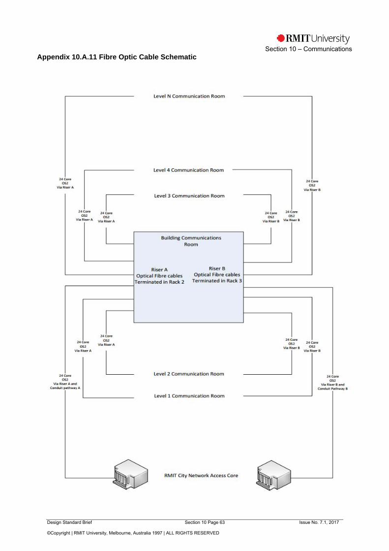
Design Standard Brief Section 10 Page 63 Issue No. 7.1, 2017
©Copyright | RMIT University, Melbourne, Australia 1997 | ALL RIGHTS RESERVED
Section 10 – Communications
Appendix 10.A.11 Fibre Optic Cable Schematic
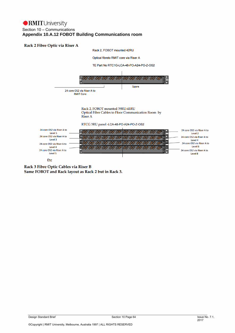
Design Standard Brief Section 10 Page 64 Issue No. 7.1, 2017
©Copyright | RMIT University, Melbourne, Australia 1997 | ALL RIGHTS RESERVED
Section 10 – Communications
Appendix 10.A.12 FOBOT Building Communications room

Design Standard Brief Section 10 Page 65 Issue No. 7.1, 2017
©Copyright | RMIT University, Melbourne, Australia 1997 | ALL RIGHTS RESERVED
Section 10 – Communications
Appendix 10.A.13 FOBOT Floor Communications Room


