DESIGN, SUPPLY, INSTALLATION AND COMMISSIONING OF LNG STORAGE & REGASIFICATION SYSTEM IN THE STATE OF MAHARASHTRA, INDIA Project No. P.013752 Document No. P. 013752 D11031 003 BGRL Tender No. BGRL/CGD/LCNG/AA/2 Bharat Gas Resources Ltd, New Delhi | INDIA PUBLIC 1 July 2019 TECHNICAL DOCUMENTATION Technical, Vol II of II, Rev. 0
Transcript
DESIGN, SUPPLY, INSTALLATION ANDCOMMISSIONING OF LNG STORAGE ®ASIFICATION SYSTEM IN THESTATE OF MAHARASHTRA, INDIA Project No. P.013752Document No. P. 013752 D11031 003BGRL Tender No. BGRL/CGD/LCNG/AA/2
Bharat Gas Resources Ltd,New Delhi | INDIA
PUBLIC
1 July 2019
TECHNICAL DOCUMENTATIONTechnical, Vol II of II, Rev. 0
SECTION - III GENERAL CONDITIONS OF CONTRACT (GCC)
SECTION - IV SPECIAL CONDITIONS OF CONTRACT (SCC)
SECTION - V FORMS AND FORMATS
P.013751 D11031 002 1 145
SECTION - VI
MAIN TABLE OF CONTENTSDESIGN, SUPPLY, INSTALLATION AND COMMISSIONING OF LNG STORAGE &
REGASIFICATION SYSTEM IN THE STATE OF MAHARASHTRA, INDIA
P.013751D 11031
003
Description
VOLUME IA OF II
STRUCTURAL STEEL WORKS
VOLUME II OF II
PTS - MECHANICAL
PTS - CIVIL CONSTRUCTION
PTS - GRAVEL FILLING
STRUCTURAL CONCRETE
SITE PREPARATION FOR EXCAVATION WORKS & BACK FILLING
EXCAVATION, BACKFILLING, COMPACTION
SEWER AND DRAINAGE SYSTEM
MISC. CIVIL AND STRUCTRUAL WORKS FOR UNDERGROUND PIPING AND OTHER CIVIL WORKS
MISCELLANEOUS ITEMS
SOIL INVESTIGATION
PLASTERING AND POINTING
DEMOLITION AND DISMANTLING
BRICK MASONRY
BARICADES
PTS-HEALTH, SAFETY & ENVIRONMENT
SCHEMATICS FOR TYPICAL LNG STORAGE ANDREGAS+LCNG/LNG DISP SYSTEM
Construction of LNG Satellite with LNG LCNG Dispensing Facility Page 1 of 1
PTS - MECHANICAL P.013751
D11077
019
BHARAT GAS RESOURCES LTD. (BGRL)
DESIGN, SUPPLY, INSTALLATION AND COMMISSIONING OF LNG STORAGE & REGASIFICATION SYSTEM IN THE STATE
OF MAHARASHTRA, INDIA
PTS - MECHANICAL
0 29.06.2019 Issued for Construction Vishal Agarwal Amitabh Ranjan Brajesh Kumar
Rev Date Subject of Revision Prepared By Checked By Approved By
Page 1 of 191
PTS - MECHANICAL P.013751
D11077
019
Rev. 0 Construction of LNG Satellite With LNG & LCNG Dispensing Facility Page 1 of 1
TABLE OF CONTENTS
1.0 GENERAL : ....................................................................................................................... 1 2.0 MAJOR APPLICABLE CODES ............................................................................................ 1 3.0 SCOPE .............................................................................................................................. 1 4.0 MAJOR EQUIPMENT ........................................................................................................ 1 ANNEXURE # 1 DETAILED SCOPE OF WORK ............................................................................. 5 ANNEXURE # 2 DATA SHEETS ................................................................................................. 10 ANNEXURE # 3 LIST OF SUPPLIERS OF MAJOR BOUGHT-OUT ITEMS .................................... 16
Page 2 of 191
PTS - MECHANICAL P.013751
D11077
019
Rev. 0 Construction of LNG Satellite With LNG & LCNG Dispensing Facility Page 1 of 18
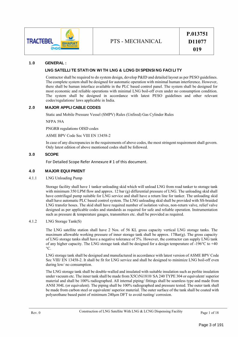
1.0 GENERAL : LNG SATELLITE STATION WITH LNG & LCNG DISPENSING FACILITY Contractor shall be required to do system design, develop P&ID and detailed layout as per PESO guidelines. The complete system shall be designed for automatic operation with minimal human interference. However, there shall be human interface available in the PLC based control panel. The system shall be designed for most economic and reliable operations with minimal LNG boil-off even under no consumption condition. The system shall be designed in accordance with latest PESO guidelines and other relevant codes/regulations/ laws applicable in India.
2.0 MAJOR APPLICABLE CODES Static and Mobile Pressure Vessel (SMPV) Rules (Unfired) Gas Cylinder Rules
NFPA 59A
PNGRB regulations OISD codes
ASME BPV Code Sec VIII EN 13458-2
In case of any discrepancies in the requirements of above codes, the most stringent requirement shall govern. Only latest edition of above mentioned codes shall be followed.
3.0 SCOPE
For Detailed Scope Refer Annexure # 1 of this document.
4.0 MAJOR EQUIPMENT 4.1.1 LNG Unloading Pump
Storage facility shall have 1 tanker unloading skid which will unload LNG from road tanker to storage tank with minimum 350 LPM flow and approx. 12 bar (g) differential pressure of LNG. The unloading skid shall have centrifugal pump suitable for LNG service and shall have a return line for tanker. The unloading skid shall have automatic PLC based control system. The LNG unloading skid shall be provided with SS-braided LNG transfer hoses. The skid shall have required number of isolation valves, non-return valve, relief valve designed as per applicable codes and standards as required for safe and reliable operation. Instrumentation such as pressure & temperature gauges, transmitters etc. shall be provided as required.
4.1.2 LNG Storage Tank(S)
The LNG satellite station shall have 2 Nos. of 56 KL gross capacity vertical LNG storage tanks. The maximum allowable working pressure of inner storage tank shall be approx. 17Bar(g). The gross capacity of LNG storage tanks shall have a negative tolerance of 5%. However, the contractor can supply LNG tank of any higher capacity. The LNG storage tank shall be designed for a design temperature of -196°C to +40 °C.
LNG storage tank shall be designed and manufactured in accordance with latest version of ASME BPV Code Sec VIII/ EN 13458-2. It shall be fit for LNG service and shall be designed to minimize LNG boil-off even during low/ no consumption.
The LNG storage tank shall be double-walled and insulated with suitable insulation such as perlite insulation under vacuum etc. The inner tank shall be made from X5CrNi1810/ SA 240 TYPE 304 or equivalent/ superior material and shall be 100% radiographed. All internal piping/ fittings shall be seamless type and made from ANSI 304L (or equivalent). The piping shall be 100% radiographed and pressure tested. The outer tank shall be made from carbon steel or equivalent/ superior material. The outer surface of the tank shall be coated with polyurethane based paint of minimum 240µm DFT to avoid rusting/ corrosion.
Page 3 of 191
PTS - MECHANICAL P.013751
D11077
019
Rev. 0 Construction of LNG Satellite With LNG & LCNG Dispensing Facility Page 2 of 18
4.1.3
Schematic for Low Pressure Re‐gasification system
The above figure shows schematic for low pressure re-gasification system wherein LNG from storage tank is directly regasified using a low pressure ambient air vaporizer. The gas pressure is then regulated using pressure regulating skid with dual stream.
4.1.3.1 Low Pressure Vaporizer
Low Pressure ambient air Vaporizer shall be provided with a 100 % standby for continuous duty operations. Each ambient air vaporizer shall be designed to work for 8 hours duty cycle and after that automatic change over to idle vaporizer to run re‐gas plant on continuous duty operations. The change-over shall be automated with the help of PLC based control system and shall require no human intervention.
Each low pressure ambient air vaporizer shall have a capacity of 2000 Sm3/hr (each) at 10 bar (g). The maximum allowable working pressure of vaporizer shall be approx. 24 Kg/cm2. The desired delivery pressure shall be 4 bar (g) after pressure control regulator. The inlet design temp for the vaporizer shall be from -196°C to +65 °C.
The low pressure atmospheric vaporizer shall be ambient air heated and shall be designed in accordance with latest version of ASME SEC VIII, DIV I and shall be fit for LNG service. The low pressure atmospheric vaporizer shall be made from Aluminium A 6061-T6/ A 6063-T5/T6 or equivalent/ superior material.
4.1.3.2 Pressure Regulating Skid
Re‐gasified natural gas shall be passed through pressure regulator skid which is equipped with twin stream pressure regulators to get natural gas at 4 Bar (g) pressure without any interruption.
4.1.3.3 High Pressure LCNG System
Odorization
Schematic for High pressure LCNG system
The above figure shows schematic for high pressure LCNG system wherein a LNG tank is connected with high pressure reciprocating pump which can pump LNG liquid to high pressure ambient air vaporizer for high pressure re‐gasification LCNG application. The system shall be designed for CNG cylinder cascade filling at minimum 250 Bar (g). The CNG shall be odorized with an odorant consisting of 70-80% TBM + 20-30% MES as per requirements of PNGRB codes.
Low Pressure Re‐Gasification System Odorization
LNG Storage
Tank
Ambient Air
Vaporizer
PRESSURE
REGULATING SKID
Gas at 4 Bar (g)
LNG
STORAGE
HIGH PRESSURE
PUMP
HIGH PRESSURE VAPORIZER
PANEL
CNG
DISPENSING
& CASCADE
FILLING
Page 4 of 191
PTS - MECHANICAL P.013751
D11077
019
Rev. 0 Construction of LNG Satellite With LNG & LCNG Dispensing Facility Page 3 of 18
i. High Pressure Reciprocating Pump
LNG tank is connected with high pressure reciprocating pump which can pump LNG liquid at 650 SCMH at min. 250 bar(g). The pump shall have a normal suction pressure of 2 bar and a max of approx. 17 bar. The delivery pressure of LCNG pump shall be minimum 250 bar.
ii. High Pressure Vaporizer
Pressurized LNG is converted to high pressure CNG after passing through high pressure ambient air vaporizer and stored into the cylinder cascade of 3000/ 4500 WL after odorization process. CNG cascade is further connected to 2 No of CNG dispenser through priority panel which will decide sequence of operation. Fixed CNG cascade has additional taping to fill other mobile CNG cascades. The high pressure vaporizer shall max a maximum operating pressure of approx. 318-325 Kg/cm2 (g) and shall be suitable for CNG cylinder filling at 250 Bar.
The high pressure vaporizer shall be ambient air heated and shall be designed in accordance with latest version of ASME SEC VIII, DIV I and shall be fit for service of LNG. The high pressure atmospheric vaporizer shall be made from aluminum A 6061-T6/ A 6063-T5/T6 or equivalent/ superior material.
4.1.4 Centralized Control & Monitoring System
LNG storage and distribution plant operations should be controlled by centralized SCADA based PLC system for better and safe operations with manual interventions where ever applicable. The offered control system (PLC & SCADA) should have provision to accommodate data and control for 1 no. future LNG storage tank. All solenoid valves should have provision for manual override. The control system should be user friendly and menu driven.
PLC System shall be supplied with licensed software required for accommodation of signals from field instruments / panels. PLC System shall comprise of fully wired free standing panels which include processors, power supply units, I/O cards, relay modules, communication modules, interfacing modules, I/O racks, Ethernet switches (manageable & stackable), serial modules, any kind of signal converters , Terminal Server / Data Concentrator, media converters, MCBs, TBs, fuses, surge protection devices, signal distribution cards, annunciators, lamps, hooter cum strobe, etc. ; HMIs (Engineering Workstation/ Operator Workstation) and licensed software for developing / modification of logics ; consoles for HMI installation ; A3 color laser printer ; necessary LAN network & accessories ; chairs, etc.
In hazardous area applications, electronic/electrical instrumentation equipment shall be suitable for hazardous area classification as per IEC. These equipment shall be intrinsically safe conforming to CENELEC standard and certified by appropriate statutory bodies (ATEX,FM, BASEFA or equivalent). Intrinsically safe systems shall be designed using zener/ IS barriers. Where intrinsically safe design is not feasible, ex-proof equipment/enclosure, certified by statutory bodies like CMRI Dhanbad/ CCOE Nagpur shall be supplied. Other acceptable safety procedures (e.g. increased safety procedure, pressurisation etc.) shall be used, wherever applicable.
4.1.5 Safety Systems
LNG satellite station shall be equipped with state of the art safety systems and interlocks for safe and reliable operations. LNG satellite station shall be equipped with gas detection and fire/temperature detection sensors with emergency shutdown buttons at strategic locations as a proactive safety measures which is continuously monitored by centralized control system. Interlocks shall be designed for operation of the plant in most safe and reliable manner with minimal human intervention.
The LEL gas detectors shall be provided as required for detection of gas leakages if any. Further the plant shall be provided with fire water network (extension of existing network), sufficient number of fire extinguishers and sand buckets.
LNG storage and distribution plant operations should be controlled by centralized SCADA based PLC system for better and safe operations with manual interventions where ever applicable.
Page 5 of 191
PTS - MECHANICAL P.013751
D11077
019
Rev. 0 Construction of LNG Satellite With LNG & LCNG Dispensing Facility Page 4 of 18
4.1.5.1 FireProtectionFacilities:
Each LNG storage facility shall be provided with continuously monitored low - temperature sensors or flammable gas detectors, which shall activate visual and audible alarms at the plant site.
Flammable gas detection system shall activate an audible and a visual alarm at level not higher than 25% of the LEL of the gas being monitored.
Fire detectors shall activate an alarm at the plant site and at a constantly attended location if the plant site is not attended continuously. If determined by an evaluation that it is necessary, then fire detectors shall be permitted to activate the ESD system
4.1.5.2 FireHydrantSystem:
A fire water supply and delivery system shall be provided based on the risk analysis. However, as a minimum a fire water storage tank of 10 % of LNG storage tank capacity or 5000 liter whichever is higher with pumping facilities and hose reel system away from the LNG storage facility shall be provided for dispersion of LNG vapor cloud in case of leakage or spillage
4.1.6 Interconnecting Piping, Fittings, Valves
The interconnecting pipes shall be double-walled vacuum jacketed. Piping, fittings, valves used shall be fit for LNG service.
Page 6 of 191
PTS - MECHANICAL P.013751
D11077
019
Rev. 0 Construction of LNG Satellite With LNG & LCNG Dispensing Facility Page 5 of 18
ANNEXURE # 1 DETAILED SCOPE OF WORK
Page 7 of 191
PTS - MECHANICAL P.013751
D11077
019
Rev. 0 Construction of LNG Satellite With LNG & LCNG Dispensing Facility Page 6 of 18
Annexure # 1 (Detailed Scope of work)
Sl. No.
Item Description
1
Design and supply of LNG vacuum insulated storage tank/s (Size – 56 KL, MAWP – 12 Barg and Quantity – 2 Nos ) - with isolation valves, instruments and interconnected piping - Level and Pressure transmitter - Emergency shut down Fire safe valves on Filling and delivery/pump lines - Junction box for connecting the instruments and valves on tank - 4 x 100% Safety valves - Common vent stack - PESO approval for the Design and TPI approval
2
LNG Unloading Pump (Quantity – 1No + 1No warehouse pump) with – - Skid mounted With Vacuum jacketed sump - Related valves and instruments including pressure and temperature sensors - with electrical panel located in the control room - Emergency shut down PB - Local vent stack
3 - Unloading Hose Trolley with Hoses – 1 sets for each pump for easy and safe hose handling - Earthing reel for ensuring effective earthing
4 Design and supply of 02 Nos. Atmospheric vaporisers (divided in 2 banks) to meet required duty cycle to supply Natural gas with valves at inlet, Flow upto – 2000 SCMH each
5
Inlet / outlet valve skids for the above vaporisers including - - automatic switchover based on time and outlet temperature - Temperature transmitters at outlet of each vaporiser - interconnecting piping and supports - valves and instruments all mounted on skid complete with cabling , pneumatic tubing and junction boxes
6
1 No of PNGRB compliant Pressure reduction system for delivery of PNG upto 2000 SCMH flow and pressure of 4 barg - 2 x 100% regulation stream with Active monitor combination with isolation valves and pressure gauges - slam shut off valve with isolation valve & pressure guage - Creep relief valve - All mounted on skid with cabling and junction box
7
Flow metering skid with RPD type flow meter - With pressure and temperature compensation - flow totalizer and indicator - with bypass valve and interconnecting piping duly mounted on skid with required valves and instruments
Page 8 of 191
PTS - MECHANICAL P.013751
D11077
019
Rev. 0 Construction of LNG Satellite With LNG & LCNG Dispensing Facility Page 7 of 18
8
PLC controlled Odoriser( for PNG stream without Odorant charge) - with controlling valves - Odorant storage tank with level indicator - Air operated dosing pump - flow sensor - interconnecting piping duly mounted on skid
9 All Interconnecting piping between skids and Equipments till PRS skid outlet within dyke wall including piping supports for PNG supply stream
10
LNG High pressure pump/s (Quantity - 2 Nos and Flow rate – 650 SCMH each with 250 bar) - with electrical control panel in control room - Temperature sensors for pre cooling and dry run protection - LP and HP side safety valves - High pressure gauge and switch - other instruments and interconnecting piping - mounted on skid
11
Design and supply of 02 Nos of atmospheric High pressure vaporisers to meet required duty cycle to supply CNG - with instruments and isolation valves for manual switchover after 8 hrs for continuous operation if required - 650 SCMH flow each
12
PLC controlled Odoriser( for CNG stream without Odorant charge) - with controlling valves - Odorant storage tank with level indicator - Air operated dosing pump - flow sensor - interconnecting piping duly mounted on skid - May be a common system with PNG based on design
13 - Sequencing/Priority Panel for sequencing of CNG flow (Quantity – 1 Nos, 10 Lines)
14 All Interconnecting piping between Tank to Pump, Pump to HP vaporizer and HP vaporizer to PESO safe area boundary including piping supports.; Interconnecting piping from PESO area limit to Dispensers/priority panel/CNG cascade fill point;
15
Cascade fill point/s (Quantity – 2 Nos) - with Manual Valves and instruments - including 1no of Mass flowmeter per point and 1 no of earthing reel per point. - with Parker or equivalent make QC coupling
16 Total safety system inclusive of Special gas detection devices, low and high temperature sensors, ESS etc. as per PESO guidelines in PESO storage area.
Page 9 of 191
PTS - MECHANICAL P.013751
D11077
019
Rev. 0 Construction of LNG Satellite With LNG & LCNG Dispensing Facility Page 8 of 18
17
Programmable logic controller (PLC) including SCADA with control panel - including software initial programming. - UPS for PLC power backup of 30 minutes - Licensed Personal computer for SCADA system
18 - Supply of all Electrical Cables from PLC to field instruments/Valves - Supply of cable trays, Electrical hardware , supports etc. - Supply of cable glands and other Electrical hardware
19 Supply of Air compressor (1 No) with Built in reservoir; Air distribution piping to all required components in PESO area and dispenser area.
20 Pump for removal of water from dyke with control mechanism
21 Fire extinguishers, sand buckets, warning signs. As required per PESO norms
22 Supply of Earthing lugs on each equipment, Spring loaded earthing reel 10mtr wire ( 1 No per unloading pump)
23 Supply of Supporting systems such as Fire water system consisting of 1 set of water tank/pump/hose as per PESO guidelines;
24 PESO approval for layout and installation excluding application fees, assistance for Form33 (PESO and Competent person fees not included),
25 Supply of all required Foundation bolts for tank and vaporizers; Supply of expansion bolts for skid and supports.
26 Hazop Study, Emergency plan and safety report per MSIHC if required
27 Installation of cables and cable trays between PLC panel and station components inside PESO storage area including all instrumentation
28 Installation and commissioning of system including piping, welding, cabling and pressure testing at site upto our Battery limit
29 Supply of Liquid Nitrogen for tank cooling during commissioning
30 Spares for commissioning
31 Supervision for unloading of tanks and Supervision of erection and commissioning of entire station.
Page 10 of 191
PTS - MECHANICAL P.013751
D11077
019
Rev. 0 Construction of LNG Satellite With LNG & LCNG Dispensing Facility Page 9 of 18
32 Transport of Equipments to site and transit Insurance, Unloading and Erection, Provision for cranes for unloading, erection and installation for all LNG Station Equipment.
33 All civil work including dyke, hard stand, foundations for Equipments , Filling of foundation pockets and other items wherever required, Yard Lighting (including Light poles located just outside the SMPV area); its cabling and control panel
34 All Local approvals/ NOC for LNG facility
35 Supply of Utilities such as Electrical power, water, Air etc. and N2 gas for testing during commissioning.
36 Spare parts for normal operation
37 Any other items not mentioned above
Page 11 of 191
PTS - MECHANICAL P.013751
D11077
019
Rev. 0 Construction of LNG Satellite With LNG & LCNG Dispensing Facility Page 10 of 18
ANNEXURE # 2 DATA SHEETS
Page 12 of 191
PTS - MECHANICAL P.013751
D11077
019
Rev. 0 Construction of LNG Satellite With LNG & LCNG Dispensing Facility Page 11 of 18
DATA SHEET FOR CRYOGENIC LIQUID STORAGE TANK
Equipment Manufacturer
Equipment Inner Vessel Outer Vessel
Storage Fluid LNG Vacuum
Installation Vertical
Approx. Capacity (Gross) 56000 Liters (+/- 5%)
Approx. Capacity (Net) 50400 Liters (+/- 5%)
Empty Weight *
Diameter * *
Total Height * *
Material of Construction AISI 304 SA 516 Gr. 70
Piping Material SA 312 TP 304
Valve Material AISI 304 body and trim
Design temp in deg C (-) 196 to 37 deg C (-) 20 deg C to 65 deg C
Design, Fabrication, Inspection and Testing EN13458-2 (+) ANNEX-C EN13458-2
Rev. 0 Construction of LNG Satellite With LNG & LCNG Dispensing Facility Page 12 of 18
DATA SHEET FOR HIGH PRESSURE ATMOSPHERIC VAPORIZER FOR LNG
1) GENERAL:
Manufacturer Name
Type Ambient Air Heated
Configuration Service Vertical
Product Vaporizer
Fluid LNG
Design Temperature (-) 196 C to 65 C
Outlet Temperature
2) DATA:
Capacity of each vaporizer 500 Nm3/hr
Qty 1 No
Manufacturing Code ASME Sec VIII Div I
Duty Cycle 16 Hours
Maximum Operating Pressure *
Design Pressure *
Hydraulic Test Pressure *
Inlet 0.5" SS NPT Female Socket
Outlet 0.5" SS NPT Female Socket
3) DESIGN:
Fin Cross Section *
Area Required (Calculation to be provided) *
Area Provided *
4) MATERIAL OF CONSTRUCTION:
Fins Aluminium A 6063 T5
Pipe, Bends and Headers ASTM A 312 TP 304 Expanded Type
Flangers Aluminium A 6063 T6
Structural and Frame SS 304
Bolts/Natural SS 304
Nuts SS 304 Nyloc Anti Vibration Nuts * Vendor to indicate
Page 14 of 191
PTS - MECHANICAL P.013751
D11077
019
Rev. 0 Construction of LNG Satellite With LNG & LCNG Dispensing Facility Page 13 of 18
DATA SHEET FOR LNG HIGH PRESSURE PUMP
Manufacturer Name Medium LNG Installation The pump must be suitable for installation on a
Thermosiphon Tank Capacity 650 SCMHSuction pressure ( Normal/Max) 2/17 Bar Delivery Pressure 250 Bar Minimum Suction Nozzle Size * Discharge Nozzle Size * Design Temperature * Pump Material of Construction AISI 304/ Equivalent Casting Grade Pump Type Positive Displacement Design Code API 674 Motor RPM 1500 Voltage 415V 50Hz 3 Phase
Scope of supply
The pump shall be supplied complete with skid, motor slide rails, control panel, Pulley for Pump and motor, Vee belts with guard, interlocks for precooling and dry run, safety /vent valves , strainer , HP gauge etc
* Vendor to indicate
Page 15 of 191
PTS - MECHANICAL P.013751
D11077
019
Rev. 0 Construction of LNG Satellite With LNG & LCNG Dispensing Facility Page 14 of 18
DATA SHEET FOR LNG UNLOADING PUMP
Manufacturer Name Medium LNG Installation Submerged in a vacuum insulated sump Capacity 350 LPM Suction pressure ( Normal/Max) Static head of LNG tanker Delivery Pressure 12 kg/cm2 Suction Nozzle Size * Discharge Nozzle Size * Design Temperature * Pump Material of Construction AISI 304/ Equivalent Casting Grade Pump Type Vertical submersible Design Code API 610 Motor RPM * Voltage 415V 50Hz 3 Phase
Scope of supply The pump shall be supplied complete with skid, interlocks for precooling and dry run, safety /vent valves , strainer , Pressure gauge, VFD etc
CONTROL PANEL
1. All safeties, trips , overloads and control required for safeoperation 2. NEMA 4 enclosure 3. Stop and start buttons 4. Protection against single phase 5. Gauges/Instruments for Volt Meter with Selector Switch, Amp. Meter with Selector Switch, Hr. run meter
* Vendor to indicate
Page 16 of 191
PTS - MECHANICAL P.013751
D11077
019
Rev. 0 Construction of LNG Satellite With LNG & LCNG Dispensing Facility Page 15 of 18
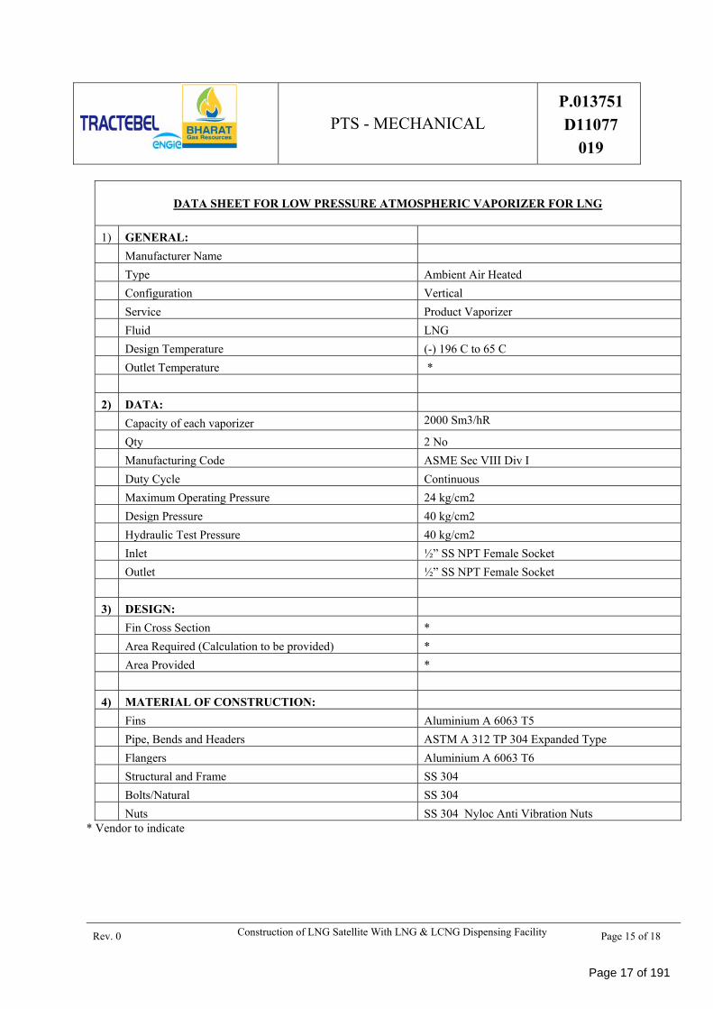
DATA SHEET FOR LOW PRESSURE ATMOSPHERIC VAPORIZER FOR LNG
1) GENERAL:
Manufacturer Name
Type Ambient Air Heated
Configuration Vertical
Service Product Vaporizer
Fluid LNG
Design Temperature (-) 196 C to 65 C
Outlet Temperature *
2) DATA:
Capacity of each vaporizer 2000 Sm3/hR
Qty 2 No
Manufacturing Code ASME Sec VIII Div I
Duty Cycle Continuous
Maximum Operating Pressure 24 kg/cm2
Design Pressure 40 kg/cm2
Hydraulic Test Pressure 40 kg/cm2
Inlet ½” SS NPT Female Socket
Outlet ½” SS NPT Female Socket
3) DESIGN:
Fin Cross Section *
Area Required (Calculation to be provided) *
Area Provided *
4) MATERIAL OF CONSTRUCTION:
Fins Aluminium A 6063 T5
Pipe, Bends and Headers ASTM A 312 TP 304 Expanded Type
Flangers Aluminium A 6063 T6
Structural and Frame SS 304
Bolts/Natural SS 304
Nuts SS 304 Nyloc Anti Vibration Nuts * Vendor to indicate
Page 17 of 191
PTS - MECHANICAL P.013751
D11077
019
Rev. 0 Construction of LNG Satellite With LNG & LCNG Dispensing Facility Page 16 of 18
ANNEXURE # 3
LIST OF SUPPLIERS OF MAJOR BOUGHT-OUT ITEMS
Page 18 of 191
PTS - MECHANICAL P.013751
D11077
019
Rev. 0 Construction of LNG Satellite With LNG & LCNG Dispensing Facility Page 17 of 18
Annexure # 3 - LIST OF SUPPLIERS OF MAJOR BOUGHT-OUT ITEMS
ITEM DESCRIPTION MAKE
MANUAL CRYOGENICC GLOBE /CHECK VALVE
BESTOBELL/HEROSE
EP OPERATED CRYOGENIC VALVES HEROSE / HABONIM/ BESTOBELL
ESD VALVES BESTOBELL/HEROSE
3-WAY MANIFOLD VALVE BALDOTA
PRESSURE SAFETY VALVE BESTOBELL/HEROSE
LEVEL GAUGE, PR. GAUGE WIKA
BALL VALVES AUDCO/MICROFINISH/ROTEX
CRYO REGULATOR & PRESSURE REGULATOR
SAMSON/ CASH
PRESSURE CONTROL REGULATOR
NIRMAL INDIA/ CHEMTROL/ PIETRO FIORENTINI
SAFETY VALVE HEROSE /LESSER/ ROCKWOOD
THERMAL RELIEF VALVE HEROSE/ REGO
PRESSURE GAUGE WIKA
TEMPERATURE ELEMENTT GENERAL INSTRUMENT
PRESSURE/TEMPERATURE TRANSMITTER
EMERSON/ SIEMENS
JUNCTION BOX BALIGA OR EQUIVALENT PESO APPROVED
PLC SYSTEM HARDWARE WITH COMPLETE CONTROL PANEL
ALLEN BRADLEY / SIEMENS
Page 19 of 191
PTS - MECHANICAL P.013751
D11077
019
Rev. 0 Construction of LNG Satellite With LNG & LCNG Dispensing Facility Page 18 of 18
LEL NG GAS DETECTOR PENTEX / HNL
EMERGENCY STOP PUSH BUTTON STATION NEAR TANK
BALIGA
ELECTRICAL CABLES RR CABLES/THERMO CABLES LTD.
CRYOGENIC PUMP CENTRIFUGAL / SUBMERGED
CRYOSTAR / ACD /VANZETTI /CRYOMECH
CRYOGENIC PUMP HP PISTON PUMP
CRYOSTAR / ACD /VANZETTI /INDIAN COMPRESSORS
HIGH PRESSURE VALVES MASCOT/TUBEFIT
CNG HIGH PR HOSE AND FITTINGS
PARKER /SWAGELOK
ODORIZER VARICON/ CPL/ INIMO
PRIORITY PANEL PARKER /TULSA
NEEDLE VALVES BALDOTA
Note :
1. Any other vendor(s) apart from as mentioned above may be accepted subject to approval by Owner/Owners representative based on past track record.
2. For the vendors of items not covered in above vendor list, but required for completion of project successfully, supplier shall take approval form Owner/Owners representative for the same during project execution. Bidder shall submit the required certifications, documents, PTR and Performance letters from clients for the same.
Page 20 of 191
PTS – CIVIL CONSTRUCTION P.013751 D 10777
020
BHARAT GAS RESOURCES LTD. (BGRL)
TRACTEBEL ENGINEERING PVT. LTD.
DESIGN, SUPPLY, INSTALLATION AND COMMISSIONING OF LNG STORAGE & REGASIFICATION SYSTEM IN THE STATE
OF MAHARASHTRA, INDIA
PTS – CIVIL CONSTRUCTION
0 29.06.2019 Issue for Construction Amresh kumar KKD/NC Chandan singh
Rev. Date Subject of revision Prepared By Checked By Approved By
Page 21 of 191
PTS – CIVIL CONSTRUCTION P.013751 D 10777
020
Rev. 0 Construction of LNG Satellite station with LNG & LCNG Dispensing Facility Page 1 of 2
Rev. 0 Construction of LNG Satellite station with LNG & LCNG Dispensing Facility Page 1 of 18
1.0 INTRODUCTION This document presents the specifications to be adopted for the Civil / Structural design of the various facilities needed for LCNG station.
2.0 SCOPE 2.1. The purpose of this document is to provide basis of design / design criteria for detailed design of the structure
needed for LCNG stations. This design basis covers general requirements and conditions needed for the design of architectural works, reinforced cement concrete structures & structural steel works for different facilities to be built at station. However, all the structures will be designed for satisfactory performance and intended usage.
Based on the above requirements, the following major Civil / Structural works are envisaged.
i) Plot Survey, soil investigation.
ii) Dyke wall
iii) Chain Link fencing with main gate at Entry and Exit
iv) Paved area inside dyke wall
v) Forecourt /RCC Pavement for the vehicle movement
vi) Paver block all around outside dyke wall
vii) Pipe & Box Culverts
viii) Site grading, Cutting & filling, green Belt development & Signage.
ix) Dewatering in the underground excavation will be done, if required.
x) Other miscellaneous civil work required for the successful completion of the job.
xi) General civil works like cable trenches, RCC pavements, roads, water harvesting system, storm water drains, Chain Link fencing, gate, etc.
xii) Miscellaneous works such as breaking and making good the existing roads; RCC works etc. wherever pipe/electrical/instrumentation cable crossings are envisaged. Dismantling of existing masonry structures, concrete and steel structures, road, fence & other related civil structures in such a fashion that site becomes suitable for construction activity. All trees to be cut & stems uprooted from the site after obtaining approval from statutory body.
xiii) All the associated Equipment Foundations & Civil / Structural works will be carried out as per the relevant standard specifications listed in General Technical Specifications.
3.0 PLOT DEVELOPMENT On finalization of the layout of LCNG stations, the plot shall be surveyed and geotechnical investigations shall be carried out by the executing agency as required. Suitable approach road and other survices shall be ensured for designed work
4.0 DESIGN CRITERIA FOR STATION WORKS 4.1. All associated foundations & civil/structural work shall be carried out as per the relevant standard specification
listed in various general technical specifications.
4.2. In case any conflict between the codes and standards listed, the same shall be brought to the notice of owner for final decision.
4.3. The design considerations given hereunder establish the minimum basic requirements of reinforced cement concrete (RCC) structures, structural steel works and masonry structures. All structures shall be designed for satisfactory performance and functions for which the same are to be constructed.
4.4. Internationally accepted commercial software viz. STAAD Pro shall be used for analysis and design of structures.
Page 24 of 191
PTS – CIVIL CONSTRUCTION P.013751 D 10777
020
Rev. 0 Construction of LNG Satellite station with LNG & LCNG Dispensing Facility Page 2 of 18
4.5. General
4.5.1. All codes referred in this document pertain to BIS (Bureau of Indian Standards) publications and bearing the prefix IS.
4.5.2. Whenever any reference to BIS code is made, the same shall be taken as the latest revision (With all amendments issued there to) on the notified date of submission of tender.
4.5.3. Apart from the BIS codes mentioned in particular in the various clauses of this document, all other relevant codes related to the specific job under consideration and/or referred to in the above-mentioned codes, shall be followed wherever applicable. Reference to some of the codes in the various clauses of this document does not limit or restrict the scope of applicability of other relevant codes.
4.5.4. All designs, detailing and construction shall strictly conform to the enclosed standards, specifications and Specific Requirements included. Only if relevant information is not available. In this document, reference to relevant BIS code shall be made. In case of discrepancy, the more stringent specification shall prevail.
5.0 REFERENCE The following Indian codes and standards shall be generally used for design of Civil and Structural works. In all cases, latest revisions with amendments if any shall be followed. Apart from the specific codes mentioned herein, all other relevant and related codes concerning the specific job under consideration and/or referred to in these codes and technical specifications shall be followed wherever applicable. (All codes shall be latest as on the date of issuing of tender/bid document).
47. Code of practice for ductile detailing of reinforced concrete
structures subjected to seismic forces : IS:13920
48. Layouts for oil and gas installations : OISD-118
49. Fire Proofing in Oil and Gas Industry (a publication of Oil Industry
Safety Directorate) : OISD-STD-164
50. Natural Gas Transmission Pipelines and City Gas Distribution
Networks : OISD - 226
Note: The above list is suggestive and not exhaustive. Apart from these basic codes any other related codes shall also be followed wherever required.
In the event of conflict between various codes and standards, the most stringent condition will apply.
Unless specified otherwise the International System of metric units (S.I.) is to be used.
Page 27 of 191
PTS – CIVIL CONSTRUCTION P.013751 D 10777
020
Rev. 0 Construction of LNG Satellite station with LNG & LCNG Dispensing Facility Page 5 of 18
DESIGN BASIS - GENERAL CIVIL 6.0 DESIGN PHILOSOPHY / CRITERIA – GENERAL
6.1. Overall Layout / Plot Plan
6.1.1. The layout/plot plan shall be prepared based on good engineering practice and applicable requirements of PNGRB, OISD-118 /226/179., Gas cylinder Rules etc.
6.1.2. After approval of the layout by the Client, the layout shall be considered for further engineering and submission for statutory approvals. Liasioning works for getting permissions/approval from concerned authorities shall be in the scope of Contractor.
6.1.3. Approval from PESO shall be taken with Client’s assistance as and when required.
6.2. Finished Floor Level (FFL)
6.2.1. FFL of the Buildings, sheds shall be generally determined with respect to top of approach road or pavement. Following schedule shall be adhered to for FFL of various buildings & sheds:
Sl. No. BUILDING/ AREA FGL/FINISHED FLOOR LEVEL
A. FGL/ Forecourt Outside road or HFL + 300mm
B Internal/Approach road Outside road or HFL + 300mm
C Paved area inside dyke wall Outside road or HFL + 300mm
Notes:
A. In case of different top reduced levels in existing asphalted roads, the highest top level of the road shall be considered.
B. FFL shall be same throughout in a building. Split levels may be considered in exceptional cases due to ground terrain etc.
7.0 SITE GRADING 7.1. The plant site shall be cleared of shrubs, vegetation, brush wood, grass, sapling etc. All the tree roots and
Vegetation shall be grubbed up and removed from plant site and the hollows filled up with earth leveled and rammed. Before removal of trees, if required, Contractor shall have to take necessary permission from the concerned office of the forest department.
7.2. Grading of the area shall be achieved by thorough rolling and compaction of the cutting area and in filling
area the earth shall be compacted in 20cm layers to achieve minimum 95% of maximum proctor density as per IS: 2720 (Part-7).
7.3. The plant FGL shall be 0.3m above High Flood Level (HFL) of the plant area or 0.3m above top level of
Existing adjacent asphalted road /National Highway/ State Highway whichever is higher.
7.4. In case of metalled road/Cart track/Mud road, Plant FGL shall be minimum 0.75m from road top level to
take care of anticipated future increase in height of road level due to change of the road to Asphalted road.
7.5. General site grading shall be done at a slope of 1:500 to 1:1000.
Page 28 of 191
PTS – CIVIL CONSTRUCTION P.013751 D 10777
020
Rev. 0 Construction of LNG Satellite station with LNG & LCNG Dispensing Facility Page 6 of 18
8.0 ROADS RCC Road with M25 grade concrete over WMM/WBM sub-base.
The thickness of crust of WBM road and RCC shall be designed as per load intensity of road based on IRC 37-2001 or as per tender standard drawing.
The sub-grade below the road shall be compacted to 95% of Procter Density and the sub-grade shall have the same slope as the road top.
9.0 PROCESS AREA / PAVED AREA / FORECOURT 9.1. Process area is the area which houses the equipment , Compressor , Metering/Filter Skid and Control Valve
Area, pipe & valve support area etc., RCC Pavement of 150mm thickness of M25 grade concrete over 100mm thick PCC (M10) shall be laid. Slope of 1 in 100 shall be maintained. The sub-grade shall be compacted to 95% of Procter Density and the sub-grade shall have the same slope as the pavement top.
9.2. Where soil condition is poor or black cotton soil is encountered, treatment as per soil report and recommendations of Geotechnical expert shall be carried out before laying of the Road, Pavement or Pathway.
9.3. For mixing of concrete, hand mixing shall not be permitted. Only weight batching concrete mixture machine shall be used for controlled mix (as per design mix).
9.4. In case of mass concreting, Ready Mix Concrete (RMC) shall be permitted.
9.5. In case of development of the existing approach road from cart track / unmetalled road / metalled road to asphalted road, the same shall be designed as per Indian Road Congress (IRC) specifications.
9.6. RCC Grade Slab in Forecourt
Complete civil works and other finishes in the fore court are included in the scope.
Brief description of major civil items shall be as follows.
a) Stone soling (150 mm thick) compacted with road roller and river sand filling in voids.
b) 100 mm thick PCC M-10 (1:3:6).
c) Laying of all required conduit, cables, pipes etc. and fixing them securely to the reinforcement bars
d) RCC M25 (to be procured from batching plant/site prepared mix) 150 mm thick laid to slope including reinforcement and inserts, PVC sleeves, expansion joints and brush finish.
e) Providing & laying 50 mm thick M25 screed over RCC floor with 4 mm dia. and 75 X75 mm wire mesh.
f) Applications of non-metallic compounds, as per manufacturer’s specifications to make the surface hard enough to bear abrasion, improve impermeability & resist weathering. The compound to be used shall be non-metallic hardener of Roff/ Fosroc/ STP/ CICO or equivalent (payable under separate item).
g) Providing non-deteriorating board in expansion joints with polysulphide sealant (payable under separate item).
10.0 CULVERTS 10.1. Culverts under roads shall be of box-shaped RCC culvert for passage of all kinds of pipelines under the roads
and sewerage systems.
10.2. Box shaped RCC culverts confirming to CPWD/PWD requirements shall be provided for crossing drains under the access roads.
10.3. Pipe culverts- Under plant roads: RCC pipes (Class NP-3 as per IS: 458)
10.4. Box shaped RCC culverts confirming to CPWD/PWD requirements shall be provided at entrance of plots or wherever required.
Page 29 of 191
PTS – CIVIL CONSTRUCTION P.013751 D 10777
020
Rev. 0 Construction of LNG Satellite station with LNG & LCNG Dispensing Facility Page 7 of 18
10.5. Electrical/Instrumentation road crossings: RCC pipes (Class NP-2 as per IS: 458)
10.6. Storm Water Box culverts: RCC Precast/ Cast-in-situ Construction (RCC M25)
11.0 STORM WATER DRAINAGE The design of storm water drainage for plot will be based on maximum hourly precipitation for storm deviation
of 20 minutes and roof drainage system will be designed for hourly precipitation for a storm of 5 min.
11.1. Run off co-efficient for drainage will be as follows:
i) Open areas - 0.5
ii) Road and paved area/ parking area - 0.70
Bituminous - 0.9
iii) Roof surface - 1.0
11.2. Sizing of drains
Design formula
SW drains shall be designed by using Manning’s Formula:
V = 1/N x R 2/3 x S ½ & Q=AV
Where V = Velocity in m/sec
N= Rhgosity,
Coefficient = 0.025 for Rock Pitched drains
S=Slope
A=Area in M2
P=Wetted Perimeter in M
R=Hydraulic mean radius (A/P)
Q=Discharge in M3/sec
11.3. The drainage system will be so designed so that the velocity of flow will be between 0.6 m / sec. to 2.5 m/sec.
11.4. Minimum Slope Preferred:
Generally for drains following minimum slope are kept:
Rectangular drains - 1:750
11.5. Flow Calculations:
Storm water Flow shall be calculated based on the following formula:
The flow from catchment area Q=CIA
Where C = Run-off Coefficient
I = Design Rainfall Intensity
A = Catchment area
12.0 STORM WATER DISPOSAL POINT Storm water shall be routed to existing storm water drain.
12.1. Drains within the plot shall carry water to storm water drains. Drainage outside the plot boundary wall will be carried away from the plot to the nearest storm water drains.
Page 30 of 191
PTS – CIVIL CONSTRUCTION P.013751 D 10777
020
Rev. 0 Construction of LNG Satellite station with LNG & LCNG Dispensing Facility Page 8 of 18
12.2. Suitable rain water harvesting for the entire plot area including roof area to facilitate recharging of bore well will be designed and executed.
12.3. Suitable arrangement in the form of drain pits, connected by buried RCC/Steel pipes for draining out water from the equipment, leakage, floor washings, firefighting, etc. will be provided complete up to plant Sewers/drain.
12.4. Rectangular brick masonry drains will be provided around the building and will be connected to existing road side drain.
13.0 SITE PREPARATION, BOUNDARY WALL AND FENCING 13.1. Site Preparation 13.1.1. The layout and level of the plot will be prepared and the benchmarks will be set. These documents will be
submitted for approval.
13.1.2. The Site preparation will conform to the requirements of the relevant sections of this design basis and GTS
13.2. Dyke Wall 13.2.1. RCC (1.5 m high) Dyke wall (with RCC columns, beam and foundation) shall be at least 1.0 m and shall not be
more than 2.0 m above average inside grade level.
13.3. Chain Link Fencing With Angle Post & Gate 13.3.1. 2.0 m high chain link fencing and MS gate shall be provided. Fencing around process area, transformer area or
wherever required as shown in drawing shall be provided. The chain link fencing shall be woven from 3.55 mm dia wire with mesh size of 50 x 50 mm shall be mounted on angle frame of size 75 x75x6. Fabrication supply, transportation, foundation shall be provided as per specification and construction drawing.
13.3.2. Barbed wire of 0.6m height shall be provided on top of chain link fencing, shall conform to IS: 278. The coating on the wire shall be smooth and relatively free of lumps, globes or points, wire with excessive roughness, blisters, salammoniac spots shall be rejected. Barbed wire shall be made from two strands of galvanised, twisted 2.5 mm (12 gauge) steel wire with 4 points of barbs. Each barb shall have two turns, tightening around one or both line wires making altogether four complete turns. The barb shall be so finished that four points are set and looked at right angles to each other.
14.0 GREEN BELT DEVELOPMENT For green belt development (approx. 20% of the plot area), 2 rows of trees @ 3m c/c shall be planted along boundary wall of the plot.
Page 31 of 191
PTS – CIVIL CONSTRUCTION P.013751 D 10777
020
Rev. 0 Construction of LNG Satellite station with LNG & LCNG Dispensing Facility Page 9 of 18
DESIGN BASIS - STRUCTURAL
15.0 DESIGN CRITERIA - GENERAL 15.1 This specification defines the design criteria and loads that shall be taken in to account for the design
of all industrial plant and non-plant structures and buildings. Shed-type structures shall completely be of steel construction. All other buildings shall be of RCC/ Composite construction.
15.2 All buildings shall be of RCC frame type construction with brick masonry walls.
15.3 Boundary wall shall be of RCC frame with RCC columns/ footings/ plinth beams & random rubble masonry as filler walls.
15.4 Bricks for masonry works shall be class 7.5 (for 75 kg/cm2) conforming to IS: 1077.
15.5 Pipe sleepers/supports contains RCC Pedestal with Footing.
15.6 The Pipes sleepers/supports have been designed as limit state method.
16.0 DESIGN LOADS AND FORCES General
Design loads will comply with the requirements of IS: 875 and IS: 1893 as minimum, unless more stringent requirements are specified herein. All buildings / structures will be in general designed for the worst possible combination of the following loads.
1. Dead load (DL);
2. Live load (LL);
3. Wind load (WL);
4. Earthquake load (SL);
5. Impact load/ Vibratory load (I);
6. Equipment load (E);
7. Surcharge load;
8. Earth pressure load;
16.1 Dead Load (DL) The dead load comprises of weights of all structural and architectural components and external loads pertaining
to all permanent construction, including walls, floor, roofs, partitions, stairways, and equipment excluding their contents. Self-weight of material may be calculated on the basis of unit weights given in IS: 875 (Part I).
Rev. 0 Construction of LNG Satellite station with LNG & LCNG Dispensing Facility Page 10 of 18
8 Glass 0.25 KN/m3
9 Stone aggregate 17.5 KN/m3
16.2 Live Load (LL) 16.2.1 Live loads shall comprise of all loads other than dead loads. This will be in general as per IS: 875 (Part II).
Other than the live loads, any other possible loads due to construction, erection, etc. shall also be considered in the design.
16.2.2 The minimum live loads to be considered for the areas involved in the structural design are given below. Loadings resulting from concentration of facilities in specific areas will be substituted where listed base loading is exceeded, involving structural design are given in IS: 875.
16.3 Wind Load (WL) Wind loads shall generally be as per IS: 875. The basic wind speed for all the stations shall be taken as 44 m/sec.
Basic wind speed, Vb = As per IS 875 (Part III)
K1 (Risk Coefficient) = As per IS 875 (Part III)
Terrain category = As per IS 875 (Part III)
Class of Structure = As per IS 875 (Part III)
Terrain, height and structure size
Factor K2 for terrain category 1 and = As per IS 875 (Part III)
Class of structure A as per Table 2
Topography factor (K3) = As per IS 875 (Part III)
Vz, design wind speed = Vb x K1 x K2 x K3
16.4 Earthquake Load (SL) The seismic forces shall be computed on the basis of importance of structure and its soil foundation system. The design value shall be calculated based on IS: 1893 (part-1& part-4): 2002. Ductility detailing of reinforcement shall be as per IS: 13920.
16.5 Surcharge Load Surcharge load will be taken as minimum 1 T/ m2 for design of boundary wall, drain and other underground
structure.
16.6 Soil and Hydrostatic Pressure Uplift on Floors - In the design of basement floors/ UG structure and similar (approximately horizontal) constructions below grade, the upward pressure of water shall be taken as full hydrostatic pressure applied over the entire plan area. The hydrostatic head shall be measured from the underside of construction. The downward load due to over burdens shall be calculated only for the volume over projected plan area (i.e., the volume of overburden beyond projected plan area (i.e., the volume of overburden beyond projected plan area shall not be considered). Factors of safety against uplift shall be 1.2.
Unit wt. of soil will be taken = As per latest soil investigation report.
Angle of repose Ø = As per latest soil investigation report.
Ka = As per latest soil investigation report.
16.7 Other Loads
Page 33 of 191
PTS – CIVIL CONSTRUCTION P.013751 D 10777
020
Rev. 0 Construction of LNG Satellite station with LNG & LCNG Dispensing Facility Page 11 of 18
Apart from the specified live loads, any other equipment load or possible overloading during construction, hydro-test, erection, etc. shall also be considered in the design. Under hydro test condition, the wind force shall be taken as 25% of normal loading.
Design of all structures shall also consider any other relevant and consequential load/stress imparted to the structure. All liquid retaining/ storage structures shall be designed assuming liquid up to the full height of wall irrespective of provision of any over flow arrangement.
All buildings and structures shall be checked and designed to satisfy the worst load combination of the above loads that produces maximum forces and effects and consequently maximum stresses. Wind and earth quake loads shall not be considered to act simultaneously.
16.8 Applicable Codes & Documents The following Indian codes and standards will be used for design of Civil and Structural works. In all cases, latest revisions with amendments, if any, will be followed. Apart from the specific codes mentioned herein, all other relevant and related codes concerning the specific job under consideration and/or referred to in these codes and technical specifications will be followed wherever applicable.
LOADS & FORCES
ii. IS: 875 : Code of practice for Design loads (other than earthquake) (All Parts) for Buildings & Structures.
iii. IS: 1893 : Criteria for Earthquake resistant design of structure.
FOUNDATION
iv. IS 1080 : Code of practice for design and construction of shallow foundations in soils (other than raft, ring and shell).
v. IS: 1904 : Code of practice for design and construction of foundations in soils- General requirements.
vi. IS: 6403 : Code of practice for determination of bearing capacity of shallow foundations.
vii. IS: 8009 (Part-I) : Code of practice for settlement of foundations.
viii. IS: 2911 : Code of practice for design and construction of Pile
(All Parts) Foundation.
CONCRETE STRUCTURES
ix. IS: 456 : Code of practice of plain and reinforced concrete.
x. IS: 383 : Specification for coarse and fine aggregates from natural source for concrete
xi. IS: 2386 : Methods of tests for aggregates for concrete
xii. IS: 1786 : High strength deformed steel bars and wires for concrete reinforcement.
xiii. IS: 4326 : Earthquake resistance design and construction of buildings.
xiv. IS: 1566 : Hard drawn steel wire fabric for concrete reinforcement.
xv. IS: 432 : Specifications for mild steel and medium tensile steel bars and hard drawn steel wires for concrete reinforcement (grade I).
xvi. IS: 13920 : Ductile detailing of reinforced concrete structures subjected to seismic forces – codes of practice.
xvii. IS: 3370 : Code of practice for concrete structures for the storage of liquid.
Page 34 of 191
PTS – CIVIL CONSTRUCTION P.013751 D 10777
020
Rev. 0 Construction of LNG Satellite station with LNG & LCNG Dispensing Facility Page 12 of 18
xviii. IS: 2212 : Code of practice for brickwork.
STEEL STRUCTURES
xix. IS: 800 : Code of practice for general construction in steel.
xx. IS: 806 : Code of practice for use of steel tubes in general building construction.
xxi. IS: 808 : Dimensions for hot rolled steel beam column, channel and angle sections
xxii. IS: 2062 : Steel for general structural purposes.
xxiii. IS: 3502 : Steel chequered plates.
xxiv. IS: 1363 : Hexagonal head bolts, screws and nuts of product grade C.
xxv. IS: 1367 : Technical supply conditions for threaded steel fasteners.
xxvi. IS: 5624 : Specification for foundation bolts.
xxvii. IS: 2016 : Plain washers.
xxviii. IS: 277 : Galvanized steel sheet (Plain and corrugated)
xxix. IS: 1230 : Cast Iron rain water pipes and fittings
xxx. IS: 1728 : Specification for sheet metal rain water pipes, normal size gutters, fittings and accessories.
xxxi. IS: 14246 : Code for continuously pre - painted galvanized steel sheets and coils
xxxii. IS:814 : Covered electrode for manual metal arc welding of carbon and carbon manganese steel.
17.0 SYSTEM OF UNITS All analysis & design will be carried out using the International System (SI) of units (KN, Meter, etc.)
18.0 BASIC ENGINEERING DESIGN DATA 18.1. Design will be based on the latest soil investigation report and groundwater table.
18.2. Building is to be designed considering life of 50 years.
19.0 ANALYSIS AND DESIGN METHODOLOGY 19.1. All the buildings will be analyzed as 3-D space frame model using software like STAAD-PRO or any other
package after approval.
19.2. Appropriate amount of live load will be considered and while calculating earthquake forces. On roofs, no
19.3. Live load will be considered while calculating earthquake loads.
19.4. Permissible stresses increase in materials will be as per respective IS code and will be considered under Wind/Seismic loading.
19.5. Appropriate load factor for Limit State Design will be considered as per code provisions.
20.0 LOAD COMBINATION 20.1. The load combinations will be generally as per IS: 875 (Part 5).
20.2. All structures shed will be designed for worst effect among the following cases.
20.3. Load combination for anchor bolt, foundation bearing check and deflection
i) DL + LL;
ii) DL + LL + SL/WL;
Page 35 of 191
PTS – CIVIL CONSTRUCTION P.013751 D 10777
020
Rev. 0 Construction of LNG Satellite station with LNG & LCNG Dispensing Facility Page 13 of 18
iii) DL + SL;
iv) DL + WL;
v) DL + WL / SL + TL;
Load combination for Steel Structure Design
vi) DL + LL;
vii) DL + LL + WL/SL;
viii) 0.8 x (DL + LL + SL/WL);
ix) DL + WL / SL;
Load combination for RCC Structure Design
x) 1.5*(DL + LL);
xi) 1.5*(DL + LL + SL/WL);
xii) 1.5*(DL + SL);
xiii) 1.5*(DL + WL);
xiv) DL + WL / SL;
21.0 FOUNDATIONS DESIGN 21.1. Foundations shall be designed as per the recommendations/ requirements given in foundation design basis,
which shall be prepared by the contractor as per the requirements specified in geotechnical data
21.2. NGL (Natural ground level) and FGL (Finished ground level) shall be marked on all drawings showing
Foundation / sub-structure details and related design documents.
21.3. If soil conditions are not favorable for spread foundation, the pile foundation (IS: 2911) work will be carried out
21.4. Safe bearing pressure (allowable net safe bearing capacity) shall be based on the following minimum
Settlement criteria under Dead Load +Live Load (or with Operating) condition:-
Type of Structures
Isolated Footings
Raft Foundations
Control room building/ canopy sheds/ structures
Equipment foundations etc.
25mm settlement 40 mm settlement
For transient loadings viz. with wind/seismic loads, settlement shall not be the criteria and safe bearing capacity based on shear criteria shall be considered.
21.5. Raft foundations shall be designed as per IS: 2950
Minimum depth of foundation for all structures shall be minimum 1.5m or as per approved soil investigation report. Factors of safety against overturning and sliding shall be as per values given in IS:456. Component of soil back fill weight over foundation slab shall be appropriately covered as foundation dead load. For stability checks the weight of soil as overburden shall be as per IS: 456.
Permissible increase in SBC/ PILE capacities (for compressive, shear and Uplift/tension) shall be as per IS codes.
21.6. The design ground water level shall be as per the approved foundation design basis and hydrostatic pressure shall be adequately accounted for in design.
Page 36 of 191
PTS – CIVIL CONSTRUCTION P.013751 D 10777
020
Rev. 0 Construction of LNG Satellite station with LNG & LCNG Dispensing Facility Page 14 of 18
22.0 REINFORCEMENT BARS
High Strength Deformed (TMT) bars of grade FE 415 /Fe 500D conforming to IS: 1786 shall be used for all structures at all stations/terminals. However, at stations/ terminals where ground water table is at a shallower depth or near coastal area causing submergence of foundations, Corrosion Resistant Steel (CRS) bars shall be used or as per geo-tech recommendation.
23.0 SPECIAL CONSIDERATIONS FOR RCC CONCRETE STRUCTURES 23.1. General/Design Methods
25.1.1 All buildings, structures, foundations, machine/equipment foundations, liquid retaining/storage structures,
Trenches, pits, pipes and cable trenches etc. shall be designed based on the codes indicated under reference and other applicable codes.
25.1.2 Minimum grade of reinforced cement concrete to be used for different structures and foundations shall be M25.Concrete Design Mix as per IS: 10262 shall be used. From Durability considerations the minimum cement content and maximum water-cement ratio shall be as under. The maximum cement content shall not exceed 450 kg/m3
25.1.3 75mm thick lean concrete of grade 1:4:8 shall be provided under all RCC foundations except under base slab of liquid retaining structures where Plain Cement Concrete (PCC) of M20 Grade shall be provided. The lean concrete & PCC shall extend 50mm beyond the foundation for normal foundations and 75mm under liquid retaining structures respectively.
25.1.4 Plain Cement Concrete (PCC) of grade M15 of minimum 150mm thickness shall be provided under all masonry wall foundations.
25.1.5 Reinforced cement concrete band of M20 grade of minimum 100mm thickness shall be provided as damp proof course at plinth level of all masonry walls. Water proofing compound shall be added in concrete.
25.1.6 All structures shall be moment-resisting frame-type construction. Detailing shall be as per provisions of IS: 13920.
25.1.7 Unless otherwise specified elsewhere in this document only Limit state method as per IS: 456 shall be followed in the design.
25.1.8 All equipment foundations, cable/pipe trenches shall be of RCC construction only. Cable/pipe trenches shall be suitably sloped and adequate provision shall be made for draining out of accumulated water to nearest manholes/pits.
25.1.9 Cable and pipe trenches shall be provided with precast (300mm wide) covers, adequately designed for the anticipated traffic movement. The covers shall, however, be designed for a uniformly distributed load of 2.0 t/m (minimum considered on 300 mm width). The walls of cable trenches shall be designed to resist a minimum surcharge load of 1.0 MT/m2 for non-hydra movement areas.
25.1.10 For hydra movement areas, the covers shall be designed for to withstand a minimum moving load of a 10 MT hydra-crane. Sealing surface of the slab shall be at least 100mm wide with structural ISA 50x50x6 edge protection embedded throughout the length of trench.
25.1.11 Foundations placed at varied depths shall be designed considering bearing capacity at that particular level with due consideration of uplift/subsoil water table.
25.1.12 If specified design depth of ground water table so warrants all underground pits, tunnels, basements, cable trenches etc. shall be leak-proof-RCC.
25.1.13 There shall be no intermixing of different grades of concrete in the same structure/structural element (excepting columns, walls etc. with element extending in both sub and super structure).
25.1.14 There shall be no intermixing of different grades of steel (main reinforcement) in the same structure.
Page 37 of 191
PTS – CIVIL CONSTRUCTION P.013751 D 10777
020
Rev. 0 Construction of LNG Satellite station with LNG & LCNG Dispensing Facility Page 15 of 18
24.0 MINIMUM COVER TO MAIN REINFORCEMENT The clear cover shall be considered over links/stirrups.
The following minimum clear cover shall be provided for RCC works.
- Slab (roof & floor), Canopy, 25mm
Cantilever, Waist slab
- Beam (roof, floor & tie), lintel 45mm
- Column, Pedestal 50mm
- Foundation slab, base slab, plinth beam 50mm
Pile Cap
a) Bottom face 100mm
b) Top and side face 50mm
Liquid Retaining Structure
a) Face in contact with liquid 45mm
b) Face away from liquid but earth 50mm
c) Free face 45mm
25.0 MINIMUM THICKNESS OF STRUCTURAL CONCRETE ELEMENTS The following minimum thickness shall be followed:
- Footings (All types including raft foundations without beams) 300mm
Page 38 of 191
PTS – CIVIL CONSTRUCTION P.013751 D 10777
020
Rev. 0 Construction of LNG Satellite station with LNG & LCNG Dispensing Facility Page 16 of 18
(Note: Tapered footings shall not have thickness
less than 150mm at the edges. Minimum average
Thickness shall not be less than 300mm)
- Slab thickness in Raft foundations
with beam & slab construction 150mm
- Walls 150mm
- Pile Cap 500mm
- Slab thickness in Raft foundations with beam
& slab construction 350mm
- Suspended floor/roof slab, walkway, canopy slab
resting on beams 125mm
- Cable/pipe trench walls & base slab 125mm
- Parapet wall 100mm
- Louvre/Fin 100mm
- Precast Trench Cover/Precast Floor Slab 125mm
26.0 MINIMUM HEIGHT OF PEDESTALS The minimum projection of pedestals supporting any steel structure/stanchion bases shall be 300/150mm above the high point of pavement/finished grade/finished floor level whichever is higher, for outdoor and indoor located pedestals respectively. The maximum projection of pedestals for staircase/ladder shall be 200mm.
27.0 MINIMUM COVER TO FOUNDATION BOLTS Minimum distance from the center line of foundation/anchor bolt to edge of pedestals shall be the maximum of the following:
i.. Clear distance from the edge of the base plate/base frame to the outer edge of the pedestal shall be minimum 50mm.
ii. Clear distance from the face of pocket to the outer edge of the pedestal shall be 100mm.
iii. Clear distance from the edge of the sleeve or anchor plate to the edge of pedestal shall be 100mm.
28.0 CONCRETE MIX a) Reinforced Cement Concrete (RCC)
Unless otherwise noted, reinforced concrete conforming to IS: 456 shall be used using 20mm and down size graded crushed stone aggregate. The minimum grade of reinforced cement concrete (RCC) to be used for all structures and foundations shall be M25.
b) Lean Concrete
Mud mat of minimum 75mm thickness of lean concrete mix 1:5:10 (by weight, using 40mm and down size grade crushed stone aggregate) shall be provided under all RCC foundations except under base slabs of liquid retaining structures for which the mix shall be M20 (by weight) and minimum thickness of mud mat shall be 100mm. Mud mat shall extend 75mm on all sides beyond the edges of base slabs in case of liquid retaining/storage structures and 50mm in case of other foundations. The exposed surface of mud mat layer in case of liquid retaining/storage structure shall be finished smooth. Lean concrete of grade1:5:10 (by weight) shall be used as filler material wherever loose subgrade exists by removing the loose soil/fill.
Page 39 of 191
PTS – CIVIL CONSTRUCTION P.013751 D 10777
020
Rev. 0 Construction of LNG Satellite station with LNG & LCNG Dispensing Facility Page 17 of 18
c) Plain Cement Concrete (PCC)
Plain cement concrete mud mat of grade M20 of minimum 150mm thickness (using 40mm and down size graded crushed stone aggregate) shall be provided under all masonry wall foundations.
Plain cement concrete of grade M20 (by weight) of minimum 40mm thickness (using 10mm & down size graded aggregates) shall be provided as damp proof course at plinth level of all masonry walls and to be coated with 3mm thick bitumen emulsion.
Making-up of levels for placing the foundation at a shallower depth from the NGL/FGL (from that as specified in the Geo-technical recommendations) by Means of filling of lean concrete is not acceptable.
d) Steel Grade Structural steel shall be of yield stress of E250 (Fe410W) conforming to grade A of IS: 2062 and Rolled section as per IS: 808 and wide flange section as per IS: 12778. Tubular steel shall conform to Yst 240 of IS: 1161. Rectangular and square steel hollow sections (i.e. RHS & SHS) shall confirm to Yst 310 of IS: 4923
28.1 Limiting Permissible Stresses Permissible stresses in structural members shall be as specified in:
IS: 800 Hot rolled sections (excluding transmission towers and switchyard structures).
IS: 801 Cold formed light gauge sections
IS: 802 Switchyard structures
IS: 806 Tubular structures
- Permissible stresses in bolts shall be as specified in:
IS: 800 Hot rolled sections
IS: 801 Cold formed light gauge sections.
IS: 802 Transmission Towers & Switch yard structures.
- Permissible stresses in welds shall be as specified in:
IS: 801 Cold formed light gauge sections.
IS: 816 Hot rolled sections
28.2 Limiting Deflection Provision of IS: 800 and relevant code shall be followed for limiting deflection of structural element
not listed below.
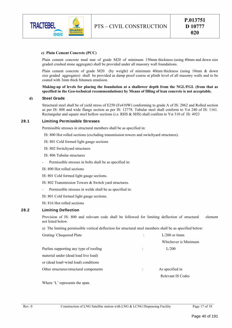
a) The limiting permissible vertical deflection for structural steel members shall be as specified below:
Grating/ Chequered Plate : L/200 or 6mm
Whichever is Minimum
Purlins supporting any type of roofing : L/200
material under (dead load live load)
or (dead load+wind load) conditions
Other structures/structural components : As specified in
Relevant IS Codes
Where ‘L’ represents the span.
Page 40 of 191
PTS – CIVIL CONSTRUCTION P.013751 D 10777
020
Rev. 0 Construction of LNG Satellite station with LNG & LCNG Dispensing Facility Page 18 of 18
b) The limiting permissible horizontal deflection for steel structure shall be Height/325.
28.3 Minimum Thickness The minimum thickness of various structural components (Hot rolled sections) shall be as given:
a) General Construction:
Trusses, purlins, side girts & bracing 6mm
Columns, beams 7mm
Gussets in trusses & girders:
i) up to and including 12m span 8mm
ii) above 12m span 10mm
Stiffeners 8mm
Base plates 10mm
Chequered plate 6mm (on plain)
Grating 3mm
29.0 PIPE SUPPORTS Pipe support foundations with minor pipe load (< 2MT) coming over unpaved area shall be designed for a foundation depth of 1.0m from FGL. For load (< 2 MT) coming over paved area support shall be lifted from the process area RCC pavement, if available For pipe load > 2 MT, depth of foundation shall be considered from NGL. In case of poor soil, the soil treatment shall be done as per Geo-tech recommendations.
30.0 STATUTORY RULES All the applicable statutory rules pertaining to factories act (as applicable for the State), Fire Safety Rules of Tariff Advisory Committee, Water Act for pollution control etc. shall be complied with.
Provisions for fire proof doors, nos. of staircases, plastering on structural members (in fire prone areas) etc. shall be made according to the recommendations of Tariff Advisory Committee.
Statutory clearance of respective NHAI, PWD, PESO and norms of State Pollution Control Board shall be followed.
Requirement of sulphate resistant cement for sub-structural works shall be decided in accordance with the Indian Standards Codes based on the findings of the detailed soil investigation shall be carried out.
Page 41 of 191
SPECIFICATION FORSTRUCTURAL CONCRETE
Z/020004
3 11.10.18 Logo Changed & Generally Revised AMK KKD NC
2 04.09.09 Logo Changed MJ AK SB
1 12.11.07 Logo Changed BK KD AM
0 23.01.07 Generally Revised MJ RG SP
B 07.02.05 Logo Changed SKS RJ RM
A 27.09.02 First Issue RJ VVA VVA
Rev Date Subject of revision Author Checked Approved
1. GENERALThis general technical SPECIFICATION is based on Indian CODES.
1.1. DEFINITIONSSubject to the requirements of the context, the terms (hereafter listed in alphabetical order) used in thisdocument are given the following meaning:
AGREEMENT Designates the agreement concluded between the OWNER and the CONTRACTOR,under which the latter undertakes to the former the GOODS and/or SERVICES according to thestipulations which are agreed and specified in the form of an order.
OWNER Designates the purchaser of the GOODS and/or SERVICES which are the subject of theAGREEMENT.
CODE Designates a set of systems and rules or international standardization documents for materials,tests, etc.
CONTRACTOR Designates the individual or legal entity with whom the order has been concluded by theOWNER. The term "CONTRACTOR" may be used indifferently for a supplier, a manufacturer, anerection contractor, etc.
DAYS - WEEKS - MONTHS Specify the number of calendar days, weeks or months and not of workingdays, weeks or months.
OWNER’S REPRESENTATIVE designates the individual or legal entity to which the OWNER hasentrusted various tasks in relation with the carrying out of his PROJECT.
GOODS and/or SERVICES Designate, depending on the case, all or part of the drawings or documents,substances, materials, equipment, structures, plant, tools, machinery,... to be studied, designed,manufactured, supplied, erected, built, assembled, adapted, arranged, commissioned and put into serviceby the CONTRACTOR under the AGREEMENT, including all the studies, tasks, works and servicesspecified by the order. The terms GOODS or SERVICES may be indifferently used one for the other asrequired by the context.
PROJECT Designates the aggregate of GOODS and/or SERVICES to be provided by one or moreCONTRACTORS.
STANDARD Designates a set of models or references, corresponding to common practice andgenerally used by the OWNER’S REPRESENTATIVE. This can be: typical standard drawings ordocuments.
SPECIFICATION Designates a document describing in some details general or particular requirementsfor specific type of works.
1.2. CODES, STANDARDS AND LEGAL REQUIREMENTSThe design, construction, materials, testing shall be in accordance with the CODES and STANDARDSmentioned in the present SPECIFICATION and with the CODES, STANDARDS and legal requirementslisted in the Particular Technical Specification (if any) for the PROJECT.
1.3. SCOPEThis SPECIFICATION covers:
a) Materials for, and the batching, mixing, transporting, placing, compacting, curing and protectingof, all concrete for use in the Civil Works;
b) Materials for, and the construction of, all formwork for cast in situ concrete:
c) Materials for, and the bending and fixing of, steel reinforcement for concrete;
d) The finishing of formed and unformed surfaces of concrete;
Page 44 of 191
SPECIFICATION FORSTRUCTURAL CONCRETE
Z/020004
Rev 3 – 11.10.18 Page 2 of 31
e) The casting, handling and placing of precast concrete units;
f) Materials for, and the use or application of, mortars, grout and rendering.
1.4. REVIEW AND/OR APPROVALWhenever a OWNER'S and/or an OWNER’S REPRESENTATIVE'S review and/or approval of adocument, to be submitted by the CONTRACTOR, is requested or before an action is implemented by theCONTRACTOR, the review and/or the approval shall always be requested in writing by theCONTRACTOR to the OWNER and/or to the OWNER’S REPRESENTATIVE before any action subjectto this review and/or approval has been taken.
An OWNER'S and/or an OWNER’S REPRESENTATIVE'S approval shall always be given in writing.
REFERENCESThe CODES referred to in this section are:
Subject Indian CODESSand IS 2116 : 1980
Testing aggregates IS 2386 : 1963
Cement & methods for testing cement IS 8112 : 1989 & IS 269 : 1989
Concrete & methods for testing concrete IS 516 : 1959
Reinforcement IS 1786 : 1985 & IS 432 : 1982
Aggregates for concrete - determination chloride content IS 383 : 1999 & IS 2386 : 1963
CODE for Labour Protection Indian labour Laws
and all derived CODES.
1.5. SUBMITTALS1.5.1. Product Data
GeneralIn accordance with the requirements of this SPECIFICATION, the CONTRACTOR shall submit thedetails specified in the following paragraphs regarding the materials covered by this SPECIFICATION.
CementsBefore orders are placed, the CONTRACTOR shall submit details of the proposed cement manufacturerswith, at the same time, sufficient information on the proposed methods of transport, storage andcertification of the cement to enable the OWNER’S REPRESENTATIVE to convince himself that therequired quantity and quality can be supplied and maintained throughout the period of construction.
Having obtained the OWNER’S REPRESENTATIVE'S approval of the source(s) of supply, and themethods of transport, storage and certification of the cement, the CONTRACTOR shall not modify orchange the approved arrangements without first having obtained the permission of the OWNER’SREPRESENTATIVE.
AggregatesThe CONTRACTOR shall submit the following details regarding the aggregates which are proposed to beused in the concrete:
Source (s)
Petrological type (s).
Admixtures
Page 45 of 191
SPECIFICATION FORSTRUCTURAL CONCRETE
Z/020004
Rev 3 – 11.10.18 Page 3 of 31
The CONTRACTOR shall submit the following details regarding the admixtures which are proposed to beused in the Concrete:
Source (s)
Types (s)
Manufacturer’s technical details.
WaterThe CONTRACTOR shall submit the following details regarding the water, proposed to be used, for themixing and/or curing of concrete, mortar, grout and rendering:
Source(s)
Chemical analysis
Physical analysis.
ReinforcementThe CONTRACTOR shall submit the following details regarding the reinforcement which is proposed tobe used:
Source(s).
Curing compoundsThe CONTRACTOR shall submit the following details regarding the curing compounds, proposed to beused:
Source(s)
Types(s)
Manufacturer's technical details.
Sealing compoundsThe CONTRACTOR shall submit the following details regarding the sealing compounds proposed to beused:
Source(s)
Type(s)
Manufacturer's technical details.
Reinforcement CouplersThe CONTRACTOR shall submit the following details regarding the reinforcement couplers, forconnecting bars in tension and compression, proposed to be used:
Source(s)
Type(s)
Manufacturer's technical details.
1.5.2. Test reportsIn accordance with the requirements of paragraph 1.2. of this SPECIFICATION the CONTRACTOR shallsubmit, as soon as possible after their completion, reports on the tests specified in paragraphs 1.5 and 3.2of this SPECIFICATION.
1.5.3. Certificates
Page 46 of 191
SPECIFICATION FORSTRUCTURAL CONCRETE
Z/020004
Rev 3 – 11.10.18 Page 4 of 31
The following requirements shall be applicable only if specifically requested by the AGREEMENTconstituent documents.
GeneralIn accordance with the requirements of this SPECIFICATION the CONTRACTOR shall submitcertificates of compliance with the specified CODES regarding the materials mentioned in the followingparagraphs.
CementAll cement shall be certified by the manufacturer as complying with the requirements of the appropriateCODES.
ReinforcementThe CONTRACTOR shall submit to the OWNER’S REPRESENTATIVE copies of the manufacturer'scertificates of tests for all supplied reinforcement.
1.5.4. SamplesThe following requirements shall be applicable only if specifically requested by the AGREEMENTconstituent documents.
GeneralIn accordance with the requirements of this SPECIFICATION, the CONTRACTOR shall supply thesamples specified in the following paragraphs.
CementsIf requested by the OWNER’S REPRESENTATIVE, the CONTRACTOR shall deliver samples ofcement(s) to an approved laboratory for the further analysis and testing envisaged in paragraphs 1.5 and3.2 of this SPECIFICATION.
ReinforcementIf requested by the OWNER’S REPRESENTATIVE, the CONTRACTOR shall deliver samples of steelreinforcement to an approved testing agency for the independent tests envisaged in paragraphs 1.5 and 3.2of this SPECIFICATION.
AggregatesThe CONTRACTOR shall deliver, to the OWNER’S REPRESENTATIVE'S site laboratory or to anapproved testing agency, as directed by the OWNER’S REPRESENTATIVE, samples of all aggregates insuch quantities sufficient for carrying out the tests as described in paragraphs 1.5 and 3.2 of thisSPECIFICATION.
1.5.5. Drawings and other detailsGeneralIn accordance with the requirements of this SPECIFICATION, the CONTRACTOR shall submit thedrawings and other details specified in the following paragraphs.
For the paragraphs, marked with (*), the requirements shall be applicable only if specifically requested bythe AGREEMENT constituent documents.
Formwork (*)The CONTRACTOR shall submit details of the methods and materials proposed for the formwork for eachelement of the works.
Details of formwork for producing special finishes shall be submitted for approval to the OWNER’SREPRESENTATIVE before any materials are brought on site.
Page 47 of 191
SPECIFICATION FORSTRUCTURAL CONCRETE
Z/020004
Rev 3 – 11.10.18 Page 5 of 31
The CONTRACTOR shall submit for approval complete construction drawings, including methoddiagrams and full supporting calculations (when required by the OWNER’S REPRESENTATIVE) of theformwork for each major structural element of the works.
Concrete placing and curingThe CONTRACTOR shall submit details of his proposed construction sequence and method including:
a) Positions of construction joints additional to those shown on the drawings
b) Pour size and sequences
c) Methods for controlling concrete temperature
d) Methods for concrete compaction
e) Curing procedures.
Bar schedules (*)Bar schedules shall be submitted to the OWNER’S REPRESENTATIVE. The layout and typical content ofbar bending schedules shall be submitted to the OWNER’S REPRESENTATIVE prior to issue them withthe drawings.
Plant detailsThe CONTRACTOR shall submit details of the types and sizes of items of equipment proposed to be usedfor the transport, placing and compacting of concrete and of the proposed manner of their use. Forconcrete mixes to be used in the works which may have a relatively low workability and a large maximumsize of aggregate, all plant and operating procedures shall be adapted to be made suitable.
Mix proposalsBefore any concrete is poured, the CONTRACTOR shall submit to the OWNER’S REPRESENTATIVEfor approval full details of the mixes he proposes to be used for each grade of concrete together with theiranticipated average target strengths.
Precast concreteThe CONTRACTOR shall submit to the OWNER’S REPRESENTATIVE for approval full details of allhis proposed arrangements for casting, handling and placing precast concrete units.
Concrete documentationThe CONTRACTOR shall send daily to the OWNER’S REPRESENTATIVE a return showing thequantities of cement, per grade of concrete, used in the permanent works and in temporary works, of theprevious day.
Temperature recordsThe CONTRACTOR shall record the daily maximum and minimum ambient shade and unshaded airtemperatures adjacent to those parts of the works where concrete is being placed or cured. TheCONTRACTOR shall send a copy of these records to the OWNER’S REPRESENTATIVE every week.
Calibration of weighing equipmentThe CONTRACTOR shall submit to the OWNER’S REPRESENTATIVE, as soon as possible after theircompletion, the results of the calibration checks specified in paragraph 2.2.6 of this SPECIFICATION.
1.6. DELIVERY, STORAGE AND HANDLING1.6.1. Cement
See also :
[ IS 8112 : 1989 ]
Page 48 of 191
SPECIFICATION FORSTRUCTURAL CONCRETE
Z/020004
Rev 3 – 11.10.18 Page 6 of 31
The cement shall be delivered to the site in bulk or in sound, properly-sealed and marked bags. Whilebeing loaded or unloaded and during transit to the concrete mixers, whether conveyed in vehicles or bymechanical means, cement shall be protected effectively from the weather. Mechanical transfer systemsshall be fully enclosed and bagged cement shall be protected by tarpaulins or other effective coverings.
If the cement is delivered in bulk, the CONTRACTOR shall provide approved silos of adequate sizes tostore a sufficient amount of cement to ensure the continuity of the works and the cement shall be placed inthose silos immediately after it has been delivered to the site. Approved precautions shall be taken duringunloading to ensure that the resulting dust does not constitute a nuisance or health hazard.
If the cement is delivered in bags, the CONTRACTOR shall provide perfectly waterproof and wellventilated sheds having a floor of wood or concrete raised clear of the ground.
The sheds shall be large enough to store a sufficient amount of cement to ensure the continuity of the workand to enable the OWNER’S REPRESENTATIVE to determine the suitability of the cement before beingused.
Each consignment shall be stacked separately therein to permit easy access for inspection, testing andapproval. When delivered at the site the cement shall immediately being placed in the above mentionedsheds and it shall be used in the order in which it has been delivered.
The CONTRACTOR shall ensure that the arrangements for the storage of the cement at the site aresufficient for the separation and identification of each consignment until the results of the sampling andtesting referred to in paragraph 1.5.4 and 2.2.1 of this SPECIFICATION are available.
1.6.2. AggregatesSee also :
[ IS 383 : 1999 ]
All aggregates for concrete shall be stored in concrete-based bins or on stages designed to preventintermixing of different aggregates and to avoid the inclusion of dirt and other foreign materials in theconcrete. Each size of aggregate shall be stored separately.
The storage bins shall be emptied and cleaned and the grading of the aggregates checked at intervals,subject to the approval of the OWNER’S REPRESENTATIVE.
1.6.3. ReinforcementAll reinforcement shall be stored above ground, racked systematically as necessary and protected from allaggressive elements to the approval of the OWNER’S REPRESENTATIVE.
1.7. QUALITY ASSURANCE1.7.1. General
The materials mentioned below shall be tested at the place of manufacturing (or elsewhere if convenientand appropriate) by an approved testing agency to ensure that they comply with the requirements of thisSPECIFICATION.
The OWNER’S REPRESENTATIVE may agree on the fact that the routine tests, carried out by themanufacturers, fulfil all or part of the requirements of this paragraph, provided that he is satisfied with themanufacturer's testing procedures.
1.7.2. CementsCements from all proposed sources shall be tested for compliance with all the requirements and by themethods, set out in paragraph 2.1.1 of this SPECIFICATION.
Where necessary the OWNER’S REPRESENTATIVE may require further representative samples of theproposed cement(s) to be taken and forwarded to an approved laboratory for analysis and testing before thesource(s) is/are approved.
Page 49 of 191
SPECIFICATION FORSTRUCTURAL CONCRETE
Z/020004
Rev 3 – 11.10.18 Page 7 of 31
All cement(s) delivered to the site shall be tested on a routine basis to enable the CONTRACTOR tosubmit the certificates required by paragraph 1.5.3 of this SPECIFICATION. The CONTRACTOR'Stesting program shall ensure that any cement delivered on site from bulk storage elsewhere, satisfies therequirements of paragraph 2.1.1 of this SPECIFICATION.
1.7.3. ReinforcementAll reinforcement delivered to the site shall be tested on a routine basis to enable the CONTRACTOR tosubmit the certificates required by paragraph 1.5.3 of this SPECIFICATION.
The OWNER’S REPRESENTATIVE may, however, order independent tests to be performed and any steelwhich does not comply in all respects with the appropriate CODES will be rejected.
1.7.4. Reinforcement couplersThe CONTRACTOR shall prepare and test three connections for each diameter and type of thereinforcement bar to be coupled in such a way as to demonstrate compliance with paragraph 2.1.13 of thisSPECIFICATION.
Test specimens shall be prepared using the materials, equipment and personnel to be applied during theworks, and they shall be prepared, as far as possible, under the conditions similar to the ones likely to beencountered during the works.
1.7.5. AggregatesTests to assess the suitability of the aggregates proposed to be used in concrete for the permanent worksshall be carried out as follows :
a) Grading
b) Magnesium Sulphate Soundness
c) Specify Gravity and Water Absorption
d) Clay, Silt and Dust Content
e) Organic Impurities
f) Sulphate and Chloride Content
g) Aggregate Crushing Value
h) Elongation and Flakiness Determination
i) Potential Alkali Reactivity, chemical and petrographic examinationThese tests shall be carried out in accordance with the appropriate Belgian CODES or foreign CODES andthe results shall comply with the limits given therein or as otherwise stated in this SPECIFICATION.
1.7.6. WaterWater proposed to be used for the production and/or curing of concrete, mortar, grout and rendering, shallbe in accordance with :
[ IS 456 : 2000 / IS : 3025 ]
1.8. SITE CONDITIONSThe attention of the CONTRACTOR is drawn to the paragraphs 3.1.4, 3.1.5 and 3.1.6 of thisSPECIFICATION regarding the requirements for concreting in specific environmental conditions.
2. PRODUCTS2.1. MATERIALS2.1.1. Cement
Page 50 of 191
SPECIFICATION FORSTRUCTURAL CONCRETE
Z/020004
Rev 3 – 11.10.18 Page 8 of 31
In principle, the cement to be used throughout the works shall be (Ordinary) Portland cement and it shallcomply with the requirements of :
[ IS 8112 : 1989 IS 269 : 1989 ]
For applying special types of cements, refer to relevant Indian Codes i.e. :
[ IS 12330 : 1988 ]
for Sulphate-resisting Portland cementThe particular technical SPECIFICATIONS might refer to other specific types of cement.
In order to ensure that all visible exposed faces of concrete have a uniform colour, the CONTRACTORshall take all necessary steps to ensure the supply of cement of uniform colour.
2.1.2. Aggregate sourcesAggregates for concrete shall be obtained from sources to be approved for this purpose by the OWNER’SREPRESENTATIVE. The CONTRACTOR shall be responsible for selecting suitable aggregates andsamples of sand and stone for the specified tests to be carried out, before any arrangements of obtainingaggregates from new or alternative sources are approved by the OWNER’S REPRESENTATIVE.Laboratory check tests of the aggregates will be performed at regular intervals to confirm their suitabilityfor concrete and the consistency of the grading.
Aggregates shall be produced to the sizes and grading specified for the various concrete mixes. Ifinstructed by the OWNER’S REPRESENTATIVE the CONTRACTOR shall carry out investigations toconvince the OWNER’S REPRESENTATIVE that there are sufficient quantities of suitable aggregatesavailable to complete the works.
The CONTRACTOR shall be responsible for all arrangements and costs involved in the exploitation ofquarries and borrow pits and he shall carry out any boring and investigations he deems necessary todetermine the precise location of the working and the manner in which the quarries and borrow pits maybe exploited efficiently and economically.
Quarries shall be run in a safe manner and on completion of the works they shall be left in a tidy state. Norocks shall be left overhanging except with the approval of the OWNER’S REPRESENTATIVE. Theaggregate winning and processing operations shall be such that they do not constitute a danger to healtheither during their operation or after completion of the works.
The CONTRACTOR shall ensure that his activities in no way interfere with existing operations beingcarried out by others, and he shall be responsible for providing his own local accesses and all plant'sfacilities.
2.1.3. Aggregates - GeneralAggregates for concrete, mortar or for any other purposes shall always be free from earth, clay, loam, soft,clayey, shaley or decomposed stone, organic matter and other impurities and shall be hard and dense. Thepercentage of hollow shells shall be limited to an approved level compatible with the production of denseconcrete to the satisfaction of the OWNER’S REPRESENTATIVE.
Aggregates for use in concrete shall be, in all respects, in accordance with :
[ IS 2386 : 1963, IS 383 : 1999 ]
except where specifically indicated otherwise (below).
Sand for use in mortar shall be, in all respects, in accordance with :
[ IS 2116 : 1980 ]
Page 51 of 191
SPECIFICATION FORSTRUCTURAL CONCRETE
Z/020004
Rev 3 – 11.10.18 Page 9 of 31
Aggregates shall not contain any materials that are deleteriously reactive with the alkalis in the cement, orany alkalis which may be additionally present in the aggregates or in the mixing water, or in water incontact with the concrete or mortar, in amounts sufficiently to cause an excessive local or generalexpansion of the concrete or mortar.
In order to ensure that all visible exposed faces of concrete have a uniform colour, the CONTRACTORshall take all necessary steps to ensure a supply of aggregates of uniform colour.
Aggregates for concrete in the permanent works shall, wherever practical, have characteristics best suitedto the minimisation of drying shrinkage and thermal shrinkage of the concrete. Such aggregates wouldhave :
a) Low drying shrinkage
b) Low modules of elasticity
c) High tensile strength
d) Low thermal expansion.
2.1.4. Fine AggregateThe fine aggregate for concrete shall be conform to :
[ IS 383 : 1999 ]
The appropriate grading zone shall be selected by the CONTRACTOR and approved by the OWNER’SREPRESENTATIVE after carrying out tests of trial concrete mixes, to determine workability and density.The grading of fine aggregate shall be such as to produce the maximum concrete density compatible withthe desired workability.
Crushed sand may be added to natural sand in proportions approved by the OWNER’SREPRESENTATIVE in order to achieve the required grading. Crushed sand alone may only be used withthe approval of the OWNER’S REPRESENTATIVE.
The amount of material passing a 75 micron fine test sieve, when tested in accordance with :
[ IS 2386 : 1963 ]
shall not exceed 2 % by weight for river sand and 3% for quarry sand.
Fine aggregate shall not contain appreciable amounts of flaky and/or elongated particles.
2.1.5. Coarse AggregateThe term "coarse aggregate" means an aggregate retained on a 5,00 mm test sieve. The grading of thecoarse aggregate shall be within the limits prescribed in :
[ IS 383 : 1999 ]
and shall be such that when the coarse aggregate is combined with the approved fine aggregate andcement it shall produce a concrete of maximum density consistent with the required workability. Minimumvalues of densities of the various grades of concrete will be fixed by the OWNER’S REPRESENTATIVEafter tests have been carried out on the site.
The amount of material passing a 75 micron fine test sieve, when tested in accordance with :
[ IS 2386 : 1963 ]
shall not exceed 1 % by weight for coarse aggregate for all concrete (including granolithic concrete).
The flakiness index and elongation index of the predominant-size fractions in each single-sized coarseaggregate, determined in accordance with :
Page 52 of 191
SPECIFICATION FORSTRUCTURAL CONCRETE
Z/020004
Rev 3 – 11.10.18 Page 10 of 31
[ IS 2386 : 1963 ]
shall not exceed 35 % by weight.
Aggregate for use in concrete which is subject to abrasion and impact shall be tested in accordance with :
[ IS 2386 : 1963 ]
2.1.6. Grading of Combined AggregateThe CONTRACTOR shall be responsible for ensuring that the combined grading of the aggregates isconstant.
The required percentage to pass any sieve size as determined by approved trial mixes shall be the targetgrading for all concrete of that type. The combined grading of the used concrete shall not vary by morethan + 4 % from the one from the trial mixes. If the estimated or measured combined grading of thepermanent concrete does not meet this requirement then a new trial mix shall be prepared for the approvalof the OWNER’S REPRESENTATIVE.
If at any time samples are proven to be unsatisfactory, the CONTRACTOR shall be required, at his ownexpenses, either to change to a new supply or to make arrangements acceptable to the OWNER’SREPRESENTATIVE to cure the situation.
2.1.7. AdmixturesAdmixtures shall only be used in the concrete or mortar with the explicit permission of the OWNER’SREPRESENTATIVE or when specified and in no circumstances will the admixtures, containing chloridesor other corrosive agents, be allowed.
Air-entraining agents shall consist of neutralised vinsol resin or other approved products.
2.1.8. WaterThe CONTRACTOR shall make his own arrangements for providing fresh water for the mixing andcuring of concrete and mortar and it shall be subject to the OWNER’S REPRESENTATIVE for approval.
In general, water to be used for the mixing and/or curing of the concrete, mortar and grout shall be freshand free from all sediment and dissolved or suspended matter which may be harmful to the manufacturingof concrete, mortar and grout.
The OWNER’S REPRESENTATIVE may request analysis of water samples to be taken from the intendedsource of supply before any concrete work is started and he may request this at intervals throughout theduration of the AGREEMENT. If, at any time, the samples are proved to be unsatisfactory, theCONTRACTOR will be requested, at his own expenses, either to change to a new supply or to makearrangements, acceptable to the OWNER’S REPRESENTATIVE, to remove the offending matter.
2.1.9. Steel ReinforcementSteel reinforcement, other than steel for pre-stressing, used in reinforced concrete shall comply with :
[ IS 1786 : 1985 ]
and with the following CODES as appropriate :
a) Hot rolled steel bars for the reinforcement of concrete shall comply with the requirements of :
[ IS 1139 : 1966 ]
b) Cold worked steel bars for the reinforcement of concrete shall comply with the requirements of :
[ IS 1786 : 1985 ]
2.1.10. Control of Chlorides in Hardened Concrete and its ConstituentsOrdinary Portland cement concrete
Page 53 of 191
SPECIFICATION FORSTRUCTURAL CONCRETE
Z/020004
Rev 3 – 11.10.18 Page 11 of 31
For concrete manufactured with ordinary Portland cement the levels of equivalent acid-soluble chlorides asNaCl shall generally not exceed the values specified below. The levels are indicative for the individualconstituents of the mix and are subject to the overriding maxima specified for the total mix, which shallnot be exceeded.
Coarse aggregatea. reinforced concrete 0,03 % by weight
b. mass concrete 0,10 % by weight
Fine aggregate
a. all concrete 0,10 % by weight
Testing of chlorides content of aggregates shall comply with :
[ IS 2386 : 1963 ]
The total estimated chloride content of any mix, including the one, present in the cement, shall not exceedthe following : (expressed as a percent by weight of cement).
1) Prestressed concrete 0.4 %
2) Conventionally reinforced concrete 0.6 %
in a moist environment and exposed to chloride.
Acceptable levels of chlorides in concrete and its constituent materials shall be reduced to two-thirds of thevalues specified in paragraphs 1 and 2 above, where sulphates are present in concentrations greater than50 % of those allowable.
Sulphate-resisting Portland cement concrete
For concrete manufactured with sulphate-resisting Portland cement the NaCl max. content by weight ofcement in the hardened concrete shall not exceed 0,10 %.
Testing by the OWNER’S REPRESENTATIVE
Independently from the CONTRACTOR'S QC (Quality Control) testing the OWNER’SREPRESENTATIVE will carry out selective tests at intervals during the production of concrete to checkthat these criteria are being achieved consistently.
2.1.11. Control of sulphates in hardened concrete and its constituentsThe levels of acid-soluble sulphates (as SO3) shall generally not exceed the values specified below. Thelevels are indicative for the individual constituents of the mix and are subject to the overriding maximaspecified for the total mix, which shall not be exceeded :
a) Coarse aggregate 0,4 % by weight
b) Fine aggregate 0,4 % by weight
The total estimated sulphate content (as SO3) of any mix, including the one, present in the cement, shallnot exceed 4 % by weight of cement in the mix.
Independently from the CONTRACTOR'S QC (Quality Control) testing (the) OWNER’SREPRESENTATIVE will carry out selective tests at intervals during the production of concrete to checkthat these criteria are being achieved consistently.
2.1.12. Acceptable level of chlorides and sulphates in any concreteThe acceptable level of chlorides and sulphates quoted in the above paragraphs shall not be considered asmean values for the whole of the Works, but shall be deemed to apply to any concrete.
2.1.13. Mechanical coupling of reinforcement
Page 54 of 191
SPECIFICATION FORSTRUCTURAL CONCRETE
Z/020004
Rev 3 – 11.10.18 Page 12 of 31
Where specified, directed, or approved by the OWNER’S REPRESENTATIVE, mechanical coupling ofreinforcement may be used. Proprietary mechanical coupling systems shall meet the requirements of thisparagraph and shall be subject to the approval of the OWNER’S REPRESENTATIVE.
The couplers for tension connections shall have a yield strength and ultimate tensile strength at least 1.2times the characteristics strength yield strength and ultimate tensile strength respectively of the bars beingcoupled.
In case the loadings are not predominantly static, the CONTRACTOR shall demonstrate that thecouplings can resist loading of a cyclic and dynamic nature.
Couplers designed for use with bars in compression only, may be used at locations where the OWNER’SREPRESENTATIVE agrees that in no case, the bar will be required to resist a tensile load.
All fixing of mechanical couplers shall be carried out either by the manufacturer's personnel or byCONTRACTOR'S staff trained by the manufacturer. Fixing of couplers shall be carried out in accordancewith the manufacturers instructions and recommendations.
2.2. MIXES AND MIXING2.2.1. Concrete Mixes
Concrete for construction shall be as detailed in the Table of Concrete Mixes and as shown by test cuberesults as specified. This list may be extended by the addition of other mixes as required and to theapproval of the OWNER’S REPRESENTATIVE.
The criteria stated in the Table of Concrete Mixes are designed to produce concrete of the requiredstrength and durability.
The specified characteristic strength is for concrete which has been cured at a temperature of 20° C + 1°C. The term "characteristic strength" represents the value of the strength of concrete corresponding to theprobability that, for a normal statistic distribution of the test results for determining the strengths bycompression tests, only 5 % of the test results have a value lower than the one determined in this way.
The mixes shall be designed to have mean strengths that are greater than the specified characteristic cubestrengths by a margin of 1.64 times the standard deviation expected from the concrete batching plant,except that no standard deviation of less than 3.5 N/mm2 shall be used as a basis for designing a mix.
Mixes shall be designed with due regard for minimum workability necessary to allow the CONTRACTORto place and compact the concrete as specified with the equipment he proposes to use in any particularsituation.
TABLE OF CONCRETE MIXES
Concretegrade
Minimumquantity of
cement kg/m³
Maximumfree water-
cement ratio
Character. strength(cube) 150 mm Cube
28 days N/mm²
M20 300 0.55 20
M25 300 0.50 25
M30 320 0.45 30
M35 340 0.45 35
M40 360 0.40 40
Where air-entrainment is specified the average air content as measured in accordance with relevant IndianCodes shall be as follows :
a) Concrete containing
Page 55 of 191
SPECIFICATION FORSTRUCTURAL CONCRETE
Z/020004
Rev 3 – 11.10.18 Page 13 of 31
40 mm max. size aggregate 4.0 % + 1.0 %
Concrete containing
20 mm max. size aggregate 5.0 % + 1.0 %
These air contents are applicable at the time of concrete placing.
Concrete for paving or non structural precast units shall have a minimum flexural beam strength of 3.5N/mm2 at 28 days.
2.2.2. Water-cement ratioThe water-cement ratio for the various mixes of concrete shall be determined by the preliminary trialmixes and shall not exceed the values given in the Table of Concrete Mixes.
Effective means shall be provided for determining the moisture content and water absorption value of thefine and coarse aggregates at all times. The CONTRACTOR will be required to have an accurateknowledge of the moisture content and water absorption values of all fine and coarse aggregates as theyreach the mixer and if necessary, he shall make adjustments to the mix by changing the moisture contentand water absorption values of all aggregates.
2.2.3. Use of admixturesIn the event of the OWNER’S REPRESENTATIVE'S permission being obtained for the use of a proposedadmixture, the concrete tests described in this section shall be carried out with the correct proportion ofadmixture incorporated in the concrete to ensure that the specified strengths are achieved. Comparisonshall be made with concrete manufactured without the admixture to prove that the density has not beenreduced. If air-entraining agents are used the density shall not be reduced by more than 5 %.
When admixtures are used in the concrete very strict control shall be maintained to ensure that the correctquantity of admixture is used at all times. The equipment to be used for dispensing and the method ofincorporating the admixture in the concrete shall be submitted to the OWNER’S REPRESENTATIVE forapproval. The dispensing unit shall be translucent such that the operator can see the discharge of theadmixture.
2.2.4. Laboratory concrete trial mixesThe below described procedure is not applicable when the concrete is supplied by a ready mix plant whichhas been approved by the OWNER’S REPRESENTATIVE or when evidence exists about a previoustesting campaign of the same nature.
Preliminary laboratory tests shall be carried out by the CONTRACTOR in the presence of the OWNER’SREPRESENTATIVE to determine the mixes which will satisfy the SPECIFICATION, with the availablematerials.
Laboratory trial mixes of concretes for use in the permanent works shall, wherever practical, be designedin such a manner as to minimise drying shrinkage and thermal shrinkage of the concrete. Such mixeswould have:
a) The largest practical maximum size of aggregate,
b) The lowest practical sand content,
c) The lowest practical slump,
d) The lowest practical temperature,
e) The lowest practical cement content,
Page 56 of 191
SPECIFICATION FORSTRUCTURAL CONCRETE
Z/020004
Rev 3 – 11.10.18 Page 14 of 31
f) The lowest practical water content.
To facilitate the above and to minimise the temperature rise within large concrete pours, water reducingand/or air entraining admixtures may be included in the mix design subject to the approval of theOWNER’S REPRESENTATIVE.
2.2.5. Initial concrete field testsFollowing the results of laboratory trial mixes, trial mixes shall be prepared under full scale site conditionsand tested in accordance with relevant Indian Codes:
During the course of these tests, panels of concrete containing representative samples of reinforcing detailsshall be cast and investigated, before hardening by the use of hand tools and after hardening by means ofcoring, as outlined in paragraph 3.2.5 of this SPECIFICATION, to assess the suitability of the mixes.
Representative samples of the materials to be used shall be taken and three trial mixes using the proposedproportions shall be made on different days. The workability of each of these three trial mixes shall be thedesigned target value and a batch of six cubes from each mix shall be made, three for test at 28 days andthree for test at 7 days. The OWNER’S REPRESENTATIVE will normally approve the proposed mixproportions provided the average 28-day strength of the three trials mixes is not less than the designedmean strength and subject to the conditions noted below.
Further trial mixes shall be made if the range, that is the maximum minus the minimum of the three cuberesults in any batch, exceeds 15 % of the average of that batch, or if the range of the three batch averagesexceeds 20 % of the overall average of the batches.
In addition to tests for properties specified in this SPECIFICATION, tests shall be carried out jointly bythe CONTRACTOR and the OWNER’S REPRESENTATIVE on field trial mixes to determine thefollowing properties:
a) Air content (where air entrained concrete is specified) ;
b) Free water-cement ratio ;
c) Workability ;
d) Wet and dry densities.
Should any of the values obtained in the above tests be unacceptable, according to the OWNER’SREPRESENTATIVE, the mixes shall be re-designed.
2.2.6. Batching and mixingBatchingThe aggregates and cement shall be batched by means of efficient weigh-batching machines except asotherwise approved by the OWNER’S REPRESENTATIVE. The machines shall be carefully maintainedand cleaned. They shall be provided with simple and convenient means of checking the accuracy ofweighing mechanism, and they shall be checked and adjusted when required by the OWNER’SREPRESENTATIVE.
When volumetric batching is permitted, the constituents shall be measured by volume in a suitable gaugebox and the volumes used shall be based on a whole bag mix.
The temperature of the cement shall be kept as low as possible by adequate shading, good air circulationand reflective protection to the storage silos, but all never exceed 40°C at the time of incorporation into themix.
A simple and convenient system of accurately varying the water supply to the concrete mixers shall beinstalled, with a suitable metering system to ensure that the amount fed into the machine can be easilycontrolled, ascertained and recorded.
Accuracy of scales
Page 57 of 191
SPECIFICATION FORSTRUCTURAL CONCRETE
Z/020004
Rev 3 – 11.10.18 Page 15 of 31
The divisions on direct reading scales for cement, aggregate and water (if the latter is measured by weight)shall be readily discernible and not less than 2.5 mm in width. They shall represent a weight not greaterthan 0.5 per cent of the nominal capacity of the appropriate weighing hopper or compartment. Digitalreadouts should display to 0.1 per cent of the nominal capacity of the appropriate weighing hopper orcompartment.
At the time of installation or reconditioning, the indicated weight, shall not vary from the correct weightby more than 0.5 per cent of the actual scale reading in the range quarter-scale to full scale capacity. Forindicated weights of less than quarter-scale capacity, the variation shall be not greater than 0.5 per cent ofquarter-scale reading. At any time of operation, the indicated weight at any point of the scale shall notvary from the correct weight by more than 1.0 per cent of the actual scale reading in the range quarter-scale to full scale capacity. For indicated weights of less than quarter-scale capacity, the variation shall benot greater than 1.0 per cent of the quarter-scale reading.
Accuracy of batchingSee also :
[ IS 4925 : 1968, IS 456 : 2000 ]
Batched materials shall be measured out within the following tolerances and shall be discharged into themixer without loss :
Cement ± 2 % of the weight of the cement in the batch;
Aggregate ± 2 % of the weight of each aggregate in the batch;
Water ± 2 % of the weight of water added to the batch;
Calibration of weighing equipmentSufficient test weights shall be kept available at the site for checking the accuracy of all scales. The scalesshall be checked at the commencement of preliminary concrete tests and checks shall be carried out atintervals as directed by the OWNER’S REPRESENTATIVE but in any case not greater than 2 weeks.
The results of these checks shall be recorded and submitted to the OWNER’S REPRESENTATIVE.
All scales shall be inspected and checked over their complete range by a specialist at least every threemonths, the results being recorded and submitted to the OWNER’S REPRESENTATIVE.
With admixture dispensers, the accuracy of measurement shall be checked at least once each month with acalibrated container, the results being recorded and submitted to the OWNER’S REPRESENTATIVE.
Mixing concrete by machineConcrete shall be mixed in batches in machines of approved type. All the concreting materials includingthe water shall be mixed together thoroughly between the time of their deposition in the mixer and beforeany portion of the mixture is discharged.
The machines shall be capable of discharging their contents while running.
Transfer of concreteThe concrete shall be discharged from the mixers and transported to the Works by means which shall beapproved by the OWNER’S REPRESENTATIVE and which shall prevent contamination (by dust, rain orother causes), segregation or loss of ingredients. The means of transport shall ensure that the concrete is ofthe required workability at the point and time of placing and is transported and placed with the minimumof delay.
2.2.7. Ready-mixed concrete
Page 58 of 191
SPECIFICATION FORSTRUCTURAL CONCRETE
Z/020004
Rev 3 – 11.10.18 Page 16 of 31
Ready-mixed concrete shall not be used unless previously approved by the OWNER’SREPRESENTATIVE and, where used, shall comply with all the requirements specified herein and anyadditional requirements of :
[ IS 4926 : 1976 ]
Ready-mixed concrete plants and mixer trucks shall be subject to the approval of the OWNER’SREPRESENTATIVE which approval may be withdrawn in the event of non-compliance with therequirements of this SPECIFICATION.
3. EXECUTION3.1. EXECUTION OF CONCRETE WORKS3.1.1. General
Except where otherwise specified herein, or directed by the OWNER’S REPRESENTATIVE, concreteworkmanship shall conform to the recommendations of :
[ IS 2386 : 1963 ]
current at the time of execution of the work.
3.1.2. Placing of concreteThe concrete shall be placed in the positions and, where shown, in sequences as indicated on the drawings,in the SPECIFICATION or as directed by the OWNER’S REPRESENTATIVE. Except where otherwisedirected, the pouring shall not start until the OWNER’S REPRESENTATIVE has examined and approvedthe positioning, fixing and condition of reinforcement and any other items to be embedded, and thecleanliness, alignment and suitability of the containing surfaces or formwork. A period of not less than 24hours notice shall be given to the OWNER’S REPRESENTATIVE to allow for his examination and, ifsatisfactory, approval of the reinforcement and formwork prior to the placing of the concrete.
The CONTRACTOR shall make due allowance in his concreting program for the period of the OWNER’SREPRESENTATIVE'S examination.
The limit of individual pours and the height of lifts shall be subject to the approval of the OWNER’SREPRESENTATIVE.
The length of element that may be poured in one operation and the elapsed time between adjacent pours inthe horizontal direction shall be subject to the prior approval of the OWNER’S REPRESENTATIVE. Thesequence of pours shall be arranged to minimise thermal and shrinkage strains.
Slabs and roof pours shall be made in an approved sequential fashion. Concrete shall not be placed inadjacent bays until 7 days, or another period of time to be approved by the OWNER’SREPRESENTATIVE, has elapsed.
The CONTRACTOR shall take all necessary measures to ensure that newly placed concrete, andparticularly the one in large pours, is protected against the effects of thermal shrinkage. The aim shall beto achieve a maximum temperature differential of 20°C within the concrete and between the concrete andthe surrounding air. The CONTRACTOR shall propose suitable insulation for the formwork and exposedsurfaces of the pour.
The concrete shall be deposited as nearly as possible in its final position without rehandling or segregationand in such a manner as to avoid displacement of the reinforcement, or other embedded items or theformwork.
Page 59 of 191
SPECIFICATION FORSTRUCTURAL CONCRETE
Z/020004
Rev 3 – 11.10.18 Page 17 of 31
Wherever possible concrete shall be placed by pumping or bottom-opening skips. Where chutes are used toconvey the concrete, their slopes shall not be such as to cause segregation, and suitable spouts or bafflesshall be provided where necessary. Concrete shall not be dropped through a free height greater than 2.0 mexcept with the approval of the OWNER’S REPRESENTATIVE. Where the work requires the concrete tobe deposited from a height exceeding 2.0 m, chutes to the OWNER’S REPRESENTATIVE'S approvalshall be used to prevent segregation of materials. Concrete shall not be placed in standing water orrunning water unless specified or approved by the OWNER’S REPRESENTATIVE. If this is the case, theconcrete shall be placed in accordance with the requirements of paragraph 3.1.7 below.
All concrete and mortar shall be placed and compacted within 30 minutes of water being added to the mixor otherwise included through damps aggregates, unless admixtures are in use. If an admixture is used,tests shall be carried out jointly by the CONTRACTOR and the OWNER’S REPRESENTATIVE todetermine the initial set time. No partially set material shall be used in the works.
Placing of concrete in each section of the work shall be carried out as a continuous operation betweenconstruction joints. The CONTRACTOR shall make adequate arrangements for standby equipment. If theplacing of concrete is unavoidably delayed due to mechanical or other breakdown then theCONTRACTOR shall as directed by the OWNER’S REPRESENTATIVE either:
a) erect stop ends and form a construction joint,
b) or
c) remove the concrete already placed and restart the operation after the breakdown has beenrectified.
3.1.3. Compacting of concreteExcept where otherwise permitted by the OWNER’S REPRESENTATIVE, concrete shall be compactedduring placing by approved pattern internal vibrators. The vibrators shall operate at a frequency of not lessthan 100 Hz and shall be designed for continuous operation. The performance of vibrators shall be such asto suit the working conditions and they shall be selected accordingly. For normal use, they shall be not lessthan 75 mm diameter and shall be subject to the OWNER’S REPRESENTATIVE for approval. The radiusof influence shall be at least 300 mm.
The vibrators shall be disposed in such a manner that the whole of the mass of concrete under treatmentshall be compacted adequately at a speed commensurate with the supply of concrete from the mixers andto the satisfaction of the OWNER’S REPRESENTATIVE.
Internal vibrators shall penetrate the full depth of the layer of concrete placed and just into the layer belowand shall be withdrawn slowly so as to avoid the formation of voids.
Vibration shall not be applied directly or indirectly to masses of concrete after the initial set has takenplace but, subject to the approval of the OWNER’S REPRESENTATIVE, revibration of the upper lift of aconcrete pour may be employed as late as the concrete will respond to the vibration in order to closesettlement cracks.
Vibration shall not be used to make the concrete flow in the formwork.
3.1.4. Concreting in adverse weatherNo concreting will be allowed to take place in the open during storms or heavy rains. In places where suchconditions are likely to occur the CONTRACTOR shall arrange for adequate protection of the materials,plant and formwork so that the work may proceed under proper cover.
Where strong winds are likely to appear, additional precautions shall also be taken to ensure protectionfrom driving rain and dust.
The OWNER’S REPRESENTATIVE may withhold approval of the starting of concreting until he issatisfied with the full and adequate arrangements being made.
3.1.5. Concreting at night or in the dark
Page 60 of 191
SPECIFICATION FORSTRUCTURAL CONCRETE
Z/020004
Rev 3 – 11.10.18 Page 18 of 31
Where approval has been given to the carrying out of concreting operations at night or in places wheredaylight is excluded, the CONTRACTOR shall provide adequate lighting at all points where mixing,transporting, placing and compacting of concrete shall take place.
3.1.6. Concrete placing temperaturesConcrete is to be manufactured, transported and placed at all times in accordance within the limitations setout in the following paragraphs.
The temperature of the concrete shall not exceed 30°C at the time of placing.
The CONTRACTOR shall take the following measures in order to control the temperature of concrete attime of hot weather:
a) Effectively shade aggregate stockpiles, cement silos, water tanks and concrete handling plant;
b) Run all concrete handling plant with flake ice to reduce the temperature of the machinery beforemixing/transporting concrete;
c) Add flake ice to the mixing water;
d) Concrete at night, if approved by the OWNER’S REPRESENTATIVE.
The following measures shall be taken :
e) All forms, moulds, reinforcement and other embedded parts, mixed and placed concrete shall beshaded from sunlight and protected from any drying wind;
f) Transit time shall be restricted to a minimum to be agreed in advance between the OWNER’SREPRESENTATIVE and the CONTRACTOR taking into account the use of admixtures etc.
The size of concrete pours may be restricted if the OWNER’S REPRESENTATIVE decides that shrinkageand other factors are a consideration for particular elements of the construction.
The CONTRACTOR shall follow the requirements of :
[ IS 7861 : 1981 ]
for concreting during cold weather.
3.1.7. Deposition concrete under waterThe arrangement for depositing concrete under water shall be such that there shall be, at all times, aminimum of disturbance of the water. Running water crossing or entering areas where concrete is to bedeposited shall be brought under control before concreting starts. The concrete to be deposited under watershall be of the grade shown on the drawings and specified in the Table of Concrete Mixes.
The concrete mix design shall be such that the concrete shall be sufficiently fluid to flow freely. Concreteshall be deposited under water by means of hopper pipes or bottom dump skips, or other method approvedby the OWNER’S REPRESENTATIVE. The method and rate of deposition shall ensure that nosegregation shall occur. Concreting shall be carried out in sections previously ordered or approved by theOWNER’S REPRESENTATIVE and shall proceed continuously in each section until completed and nointerval shall be allowed to elapse while the work is in hand.
If concreting under water is done by hopper pipe, the bottom of the hopper pipe shall always be buried inthe concrete and care shall be taken not to allow the pipe to empty as it is moved over the area. Ifconcreting under water is carried out by bottom dump skip, canvas or other approved covering shall beused to cover the surface of the concrete in the skip before it is lowered into the water. The doors of theskip shall be opened only when the skip is resting on the bottom with no tension in the support cable. Afteropening, the skip shall be lifted gradually so that the concrete flows out steadily.
Page 61 of 191
SPECIFICATION FORSTRUCTURAL CONCRETE
Z/020004
Rev 3 – 11.10.18 Page 19 of 31
3.1.8. FormworkGeneralForms shall be constructed from sound materials of sufficient strength, and shall be properly braced,strutted and shored, to ensure rigidity throughout the placing and compacting of the concrete. Forms shallbe constructed in such a way that they can be removed without shock or vibration to the concrete. Internalties shall be made of metal and shall either be capable of complete removal without damage to the concreteor, if remaining permanently embedded in the concrete, be no nearer to any finished surface than thelargest value of 50 mm or the specified cover to reinforcement. The resulting cavity shall be so formed asto permit satisfactory filling as specified hereafter.
All joints shall be close fitting to prevent leakage of grout and at construction joints the formwork shall besecured tightly against previously-cast or hardened concrete to prevent stepping or the formation or ridgeson exposed surfaces.
Formwork shall be constructed to provide the correct shape, lines and dimensions of the concrete shownon the Drawings. Due allowance shall be made for any deflection which will occur during the placing ofconcrete within the forms.
Panels shall have true edges to permit accurate alignment and to provide a neat line with adjacent panelsand at all construction joints. All panels shall be fixed with their joints either vertical or horizontal, unlessotherwise specified or approved. When chamfers are to be formed the fillets shall be cut accurately to thecorrect sizes to provide a smooth and continuous chamfer.
The CONTRACTOR shall make due allowance for the renewal and/or repair of formwork in case it has tobe re-used.
Rough formworkWhere rough formwork is specified, the form may be constructed of plain, butt-jointed properly-seasonedsawn timber unless otherwise instructed by the OWNER’S REPRESENTATIVE.
The tolerances are stated here below. The minimum specified cover to the reinforcement shall bemaintained at all points. Abrupt irregularities or surface discontinuities shall not exceed 5 mm in height.
Wrought formworkWhere wrought formwork is specified, the forms shall be of steel or properly-seasoned plywood and shallbe such as to produce a smooth and even surface free from irregularities, with joints flush with the surface.The minimum specified cover to the reinforcement shall be maintained at all points.
Lined formworkWhere lined formwork is specified the forms shall be lined with clear lacquered extra-hard hardboard, orother similar lining which will produce a finish acceptable to the OWNER’S REPRESENTATIVE. Thepanels of the lining material, and the forms, shall be fixed with close flush joints.
Formwork tolerancesWall thickness
The tolerance, expressed in cm, on each linear dimension e (in cm) is equal to 1 33/ e and anyhowlimited to 4 cm.
Exposed surfaces of concreteThe finished faces of all concrete work shall be sound, solid and free from defects. All exposed arises shallhave a 25 mm x 25 mm chamfer unless otherwise specified.
No rendering of imperfect concrete faces will be allowed and any concrete that is defective in any way,including colour, shall be cut out and replaced to such depths, or be improved in such a way as directed bythe OWNER’S REPRESENTATIVE.
Page 62 of 191
SPECIFICATION FORSTRUCTURAL CONCRETE
Z/020004
Rev 3 – 11.10.18 Page 20 of 31
Preparation of formwork for concretingThe formwork shall be coated with an approved mould oil and all excess shall be removed carefully.Mould oil shall not be allowed to come into contact with concrete already placed or with reinforcement.
Before concrete is placed, all formwork and supports shall be cleaned thoroughly. Temporary openingsshall be provided to assist in the removal of the rubbish.
Concrete shall not be placed until the relevant formwork has been inspected and approved by theOWNER’S REPRESENTATIVE although the giving of this approval does not relieve theCONTRACTOR from his responsibilities concerning the requirements of soundness, finish and accuracy,specified elsewhere.
A period of not less than 24 hours notice shall be given to the OWNER’S REPRESENTATIVE to allowfor his examination and, if satisfactory, approval of the reinforcement and formwork prior to the placing ofthe concrete.
Removal of formworkForms shall be removed in such a way that they do not damage the concrete. No forms shall be removeduntil the concrete has gained sufficient strength to support itself. Centres and props may be removed whenthe member being supported has gained sufficient strength to carry itself and the load to be supported on itwith a reasonable safety factor.
The following table is a guide to the minimum periods which must elapse between the completion of theconcreting operations and the removal of formwork. Notwithstanding this table, no prop nor formworkshall be removed without the permission of the OWNER’S REPRESENTATIVE and this permission shallnot relieve the CONTRACTOR from his responsibilities for the safety of the structure.
Vertical sides of beams, walls,
columns - lift not exceeding 1.2 mm 12 hours
Vertical sides of beams, walls,
columns - lift exceeding 1.2 mm 36 hours
Soffits of beams and main slabs
(props left under) 5 days
Beams and main slabs - removal of
props 18 days
After removal of formwork no remedial works shall be attempted until the work has been inspected by theOWNER’S REPRESENTATIVE. If, according to the OWNER’S REPRESENTATIVE, any defect cannotbe cured to his satisfaction, he may direct the CONTRACTOR to replace such work at theCONTRACTOR'S expense.
3.1.9. ReinforcementPreparation and fixing of steel reinforcement
Steel rod reinforcement shall be cut, bent and fixed in accordance with:
[ IS 2502 : 1963 ]
Generally it shall be bent cold in a manner which will not damage the material. Bending hot at a cherryred heat (i.e. not exceeding 840°C) may be allowed except for bars which depend for their strength on coldworking. Bars bent hot shall not be cooled by quenching.
Bends, cranks or other labours on reinforcing bars shall be formed carefully in accordance with:
[ IS 2502 : 1963 ]
Page 63 of 191
SPECIFICATION FORSTRUCTURAL CONCRETE
Z/020004
Rev 3 – 11.10.18 Page 21 of 31
and with the working drawings.
The length of laps shall be calculated in accordance with:
[ IS 456 : 2000 ]
The number, size, form and position of all steel reinforcing bars, ties, links, stirrups and other parts of thereinforcement shall be in accordance with the Drawings.
All parts of the reinforcement shall be maintained in the correct position in the forms withoutdisplacement during the process of vibrating, tamping and ramming the concrete in place. TheCONTRACTOR shall provide all necessary distance pieces and spacer bars to maintain the reinforcementin the correct position. Any ties, links or stirrups connecting the bars shall be tied so that the bars areproperly braced and the inside of bends shall be in contact with the bars around which they are intended tofit. Bars shall be bound together with best black annealed mild steel wire approximately 1.5 mm diameteror other approved binders. Wire binding shall be twisted tight with proper pliers. The free ends of thebinding wire shall be bent inwards.
Before any steel reinforcement is embedded in the concrete any loose rust and any oil, grease, saltcontamination, products and causes of pitting, or other deleterious matter shall be removed from it, by gritblasting, mechanical wire brushing and/or washing. The method of removal to be adopted will depend onthe degree of contamination and/or corrosion and shall be to the approval of the OWNER’SREPRESENTATIVE. Partially-set concrete which may have adhered to exposed bars during previousconcreting operations shall likewise be removed.
Reinforcement left projecting temporarily from the concrete at construction or other joints shall not be bentout of position during the period in which concreting is suspended, except with the approval of theOWNER’S REPRESENTATIVE. When such approval is given the reinforcement shall be bent out over asuitably-sized former to prevent any damage to, or over-stressing of, the reinforcement.
Electric arc welding may be permitted in some locations for joining bars, subject to the approval of theOWNER’S REPRESENTATIVE.
Cover to reinforcementThe concrete cover to reinforcement shall be in accordance with the drawings. If no cover is specified onthe drawings, the CONTRACTOR shall refer this matter to the OWNER’S REPRESENTATIVE.
No pieces of steel, timber blocks or materials other than approved concrete or plastic spacers shall bepermitted for use as cover blocks or spacers.
Where concrete spacing blocks are used, they shall be of similar quality to the concrete specified for theparticular element of the structure. For concrete having a characteristic strength of 30 N/mm2 or greater,the spacing blocks shall comply with the requirements of this SPECIFICATION for water absorption andthe ties shall be made from non-metallic material.
The cover to mechanical couplers shall be in accordance with this paragraph.
3.1.10. Construction jointsConcreting shall be carried out continuously up to construction joints, the position and arrangement ofwhich shall be as indicated on the drawings or as approved previously by the OWNER’SREPRESENTATIVE. The CONTRACTOR shall allow for working beyond the ordinary working hourswhere necessary in order that each section of concrete may be completed without any lapse while the workis in hand.
All construction joints shall be formed square to the work. Keyways shall be formed in all horizontal andvertical construction joints except where ordered to be omitted by the OWNER’S REPRESENTATIVE.
Construction joints shall be located, and the sequence of concreting arranged, to minimise the effect ofshrinkage and thermal strains in the setting and hardened concrete and in subsequent pours.
Page 64 of 191
SPECIFICATION FORSTRUCTURAL CONCRETE
Z/020004
Rev 3 – 11.10.18 Page 22 of 31
When work is resumed on a surface of concrete which has set, the whole surface shall be roughened orscabbed thoroughly with suitable tools so that no smooth skin of concrete which may be left from previouswork is visible and that all aggregates and solid matrix around them are exposed.
If according to the OWNER’S REPRESENTATIVE any deleterious materials have come into contact withthe concrete of the construction joint the concrete shall be cut back to such depth as the OWNER’SREPRESENTATIVE shall direct and the roughened surfaces shall be brushed and watered immediatelybefore depositing concrete.
If according to the OWNER’S REPRESENTATIVE doubt exists about the soundness of the joint, then theCONTRACTOR shall take all steps considered necessary to investigate and cure any defects, to theapproval of the OWNER’S REPRESENTATIVE.
In water-retaining structures all construction joints shall require the use of an approved type of water barand the joint shall be sealed at the liquid face(s) where no special seal coating of that face by a waterproofsealant is specified.
3.1.11. Design JointsContraction, expansion and other movement joints shall be positioned as shown on the drawings.
Contraction joints in non-water-retaining structures, where specified, shall be formed as deliberate planesof discontinuity in the concrete structure.
To form such a joint the face of the concrete slab or block first formed shall be painted with two coats ofapproved rubber bitumen paint before the adjoining slab or block is concreted.
The adjoining slab or block shall be cast with a suitable groove against the joint to accept sealant. Theexposed edges of the joints shall be chamfered and sealed with an approved polysulphide rubber sealingcompound applied over bond breaking tape at the black of the joint rebate.
When according to the OWNER’S REPRESENTATIVE a contraction joint is likely to be contaminatedwith deleterious materials, the joint shall be sealed off immediately with an approved sealing compound assoon as striking of the formwork has been completed.
Expansion and other movement joints in non-water-retaining structures, where specified, shall be formedin the same way as contraction joints but in addition an approved compressible filler shall be placed in thejoint to provide freedom for the adjacent concrete slabs to move.
The adjoining slab shall be cast with a suitable groove against the joint to accept sealant. The exposededges of the joints shall be chamfered and sealed with an approved polysulphide rubber sealing compound.
Where a design joint occurs in a water-retaining structure, or where otherwise ordered, the joint shall bemade water-tight by the provision of a continuous water stop strip as specified by the OWNER’SREPRESENTATIVE, fixed across the joint where shown on the drawings. Special care shall be taken toensure that the concrete is well worked against the embedded parts of the strips and is free fromhoneycombing.
Precautions shall be taken to protect any projecting portions of the strips from damage during the progressof the works and, in the case of rubber and plastic, from light and heat.
In the case of copper water stop where directed bituminous painting shall be applied to the lips of the loopand the loop shall be filled with a bituminous compound, these applications being made before the strip isburied in the concrete.
The method of jointing water stops shall be in accordance with the manufacturer's instructions and to theapproval of the OWNER’S REPRESENTATIVE.
3.1.12. Reinforced concrete and mass concrete - generalConcrete shall be of the grades specified on the drawings and detailed in the Table of Concrete Mixes.
Page 65 of 191
SPECIFICATION FORSTRUCTURAL CONCRETE
Z/020004
Rev 3 – 11.10.18 Page 23 of 31
Concrete shall be placed generally as specified in the relevant clauses. It shall be placed in small quantitiesand shall be compacted thoroughly. The concreting of individual members shall be continuous withoutstoppage up to a pre-arranged construction joint or until the member is completed. Concreting shall befinished off in such manner that each member shall be monolithic with the adjoining members and withany concrete to which it is connected.
The concrete shall be well protected against the action of the weather.
Where new concrete is to be deposited on concrete already set, the surface of the latter shall be prepared asspecified in paragraphs 3.1.10 and 3.1.13 of this SPECIFICATION.
All reinforced concrete work shall be matured for such a period as the OWNER’S REPRESENTATIVEmay direct before it is charged with loads of any kind.
3.1.13. Preparation of surfaces to receive concreteBefore concrete for reinforced concrete work is deposited on a natural formation, a screed of blindingconcrete (lean concrete), as specified on the Drawings and detailed in the Table of Concrete Mixes, shallbe placed over the ground below the underside level of the reinforced concrete to form a hard even surfaceon which to construct the latter.
Immediately before depositing concrete on or against a surface of masonry, brickwork, old concrete or thelike, the following preparation shall be done. All loose material shall be removed and the surface washeddown; all seepages of water emerging at the surface shall be stopped as far as possible or suitablychannelled or piped away from the work. On upward facing horizontal or near horizontal surfaces a layerof 2:1 sand-cement mortar shall be spread over the surface of the section to be concreted if so directed bythe OWNER’S REPRESENTATIVE.
3.1.14. Mass concrete backing to masonry or brickworkThe water-cement ratio of mass concrete backing to masonry or brick facing shall be increased comparedwith that of concrete mixed for placing against timber forms by such an amount as necessary according tothe OWNER’S REPRESENTATIVE to compensate for the absorption of moisture by the masonry orbrickwork. Before any concrete is placed, the mortar joints in the facework shall have thoroughlyhardened, and the back of the facing shall be thoroughly wetted. The concrete shall be tamped carefullyround any ties or bond stones, and mortar from the concrete shall be worked carefully into the open jointsin the back of the facework.
3.1.15. Curing and protectionImmediately after compaction and for at least 7 days thereafter all concrete shall be protected againstharmful effects of sunshine, drying winds, cold, rain or running water to the satisfaction of the OWNER’SREPRESENTATIVE. During this period the measures given in this clause shall be taken to prevent theloss of moisture from the concrete and to minimise thermal stresses caused by the difference intemperature between the surface of the concrete and the core of the concrete mass. No other methods shallbe employed except with the OWNER’S REPRESENTATIVE'S approval.
Unless otherwise agreed by the OWNER’S REPRESENTATIVE, curing of horizontal surfaces shall becarried out as follows:
a) Polythene sheeting shall be placed immediately after finishing.
b) After final set has taken place, the polythene shall be replaced by wet hessian which shall then beimmediately covered with polythene.
c) Measures shall be taken to ensure that the hessian is always damp.
Page 66 of 191
SPECIFICATION FORSTRUCTURAL CONCRETE
Z/020004
Rev 3 – 11.10.18 Page 24 of 31
d) After 7 days the hessian and polythene may be removed and an approved aluminised or whitepigmented resin based curing compound sprayed on the surface, as an alternative to retaining thehessian and polythene in place for at least another 7 days.
e) Concrete shall be shaded as approved by the OWNER’S REPRESENTATIVE.
f) Where specific surface textures are required (e.g. brush finishing on road slabs) then alternativemethods of curing may only be employed with the approval of the OWNER’SREPRESENTATIVE.
Unless otherwise agreed by the OWNER’S REPRESENTATIVE curing of vertical surfaces shall becarried out as follows :
g) Immediately after the stripping of formwork, the member shall be wrapped with wet hessian andthen covered with polythene which shall be held, firmly in place.The hessian shall not be allowed to dry out.
h) After an initial curing period of 7 days the hessian and polythene may be removed. Withoutundue delay the concrete surface shall be sprayed with an approved aluminised or whitepigmented resin-based curing compound as an alternative to retaining the hessian and polythenein place for at least another 7 days.
Where water is to be used for curing concrete it shall be fresh water in accordance with the requirementsof this SPECIFICATION.
Where the use of a curing compound is proposed, the particular compound and method of application shallbe subject to the approval of the OWNER’S REPRESENTATIVE. The rate of application of an approvedcompound shall be strictly in accordance with the manufacturer's recommendations.
Where timber or other insulating formwork is used it shall either be struck in accordance with theSPECIFICATION or be left in place until such time after the temperature peak is reached as theOWNER’S REPRESENTATIVE may direct.
Air circulation shall be prevented as far as possible along the exposed faces of concrete during the curingperiod.
All joints which are to be filled with sealing compound, or surfaces formed as construction joints, shall beprotected in a manner which will ensure that no curing compound is placed on the bonding surface, e.g. byplacing wet hessian.
The protection shall be such as will ensure proper curing of the joint surface and adjacent concrete.
All concrete shall be protected from anything likely to interfere with the process of setting. No load of anykind shall be imposed upon any concrete member until the concrete has hardened sufficiently to resist theimposed load.
The surfaces of the concrete shall be protected from contamination of any sort.
When curing membranes are used they shall be compatible with waterproofing or other materials that maybe applied subsequently to the surface of the concrete.
3.1.16. Concrete surface finishes3.1.16.1 Absence of defects
All concrete shall be dense, sound, even textured and free from defects both internally and externally.
3.1.16.2 Fine face finish to formed surfacesWhere a formed surface of concrete is required to have a "fine face finish", the formwork used shall belined formwork. On removal of the formwork the face of the concrete shall be rubbed smooth withCarborundum blocks whilst the concrete is green and all small holes shall be stopped with cement mortarof such a mix as to dry out with the same colour as the adjacent concrete.
Page 67 of 191
SPECIFICATION FORSTRUCTURAL CONCRETE
Z/020004
Rev 3 – 11.10.18 Page 25 of 31
3.1.16.3 Finishes to concrete surfaces without formworkWhere, on an upward facing horizontal or near horizontal surface which does not require formwork andwhich will neither be exposed to view nor receive any subsequent surface treatment, no particular finish iscalled for. The surface shall be that produced by the proper placing and compacting operations withoutfurther labours, provided a reasonably plane surface is produced.
3.1.16.4 Screeded finishWhere a Screeded finish is specified, it shall obtained by screeding. This shall be done, immediately afterthe compacting of the concrete, by the slicing and tamping action of a screed board running on the topedges of the formwork, or on accurately-set screeding guides, to give a dense concrete skin, true to line andlevel. The finished surface shall be plain or with an even texture of parallel ribs as may be directed by theOWNER’S REPRESENTATIVE.
3.1.16.5 Floated finishWhere a floated finish is specified, it shall be obtained by first screeding the concrete as described in thepreceding paragraph then leaving it until the concrete has stiffened and the moisture film has disappeared.Floating shall then be carried out with a steel or wooden float to produce either a "glossy" surface or a"sand paper" surface as required. Working shall be kept to a minimum compatible with a good finish. Thesurface shall be true to the required profile to fine tolerance. Whenever necessary a properly-constructedoverhead cover shall be erected before the work is commenced to prevent the finished surface from beingmarred by raindrops or dripping water.
A floated finish shall be provided to all concrete surfaces which may be exposed to view in the finishedworks except where otherwise shown on the drawings.
3.1.16.6 Exposed aggregate finishWhere an exposed aggregate finish is specified, then immediately after removal of the forms the surface ofthe concrete shall be well scrubbed down by means of stiff wire brushes and water or other approvedmethods to remove the cement slurry from the surface and expose the aggregate.
3.1.17. Bush hammered finishNot less than 3 weeks (for ordinary Portland or sulphate-resisting Portland cement concrete) after pouringhas been completed, the exposed surface shall be bush hammered to remove the cement from the surfaceand expose the aggregate. Bush hammers shall be of an approved type, and they shall be worked to within12 mm of all corners and arises, the treatment of the remaining 12 mm borders being by means of suitablehand chisels to produce an effect similar to that of the adjoining bush-hammering.
Bush hammers shall be kept perpendicular to the surface being worked and care shall be taken to ensurethat only the surface mortar and the irregular projections of the aggregate are removed without anyfracturing or loosening of the portions left embedded. As the bush-hammering is completed, the surface sotreated shall be washed with water and scrubbed down with a stiff brush. All finished surfaces shall be ofan even and uniform appearance with the exposed aggregate clean and free from film.
3.1.18. Use of chemical surface retardersThe use of a chemical surface retarder will only be permitted as an alternative means of producing adecorative exposed aggregate finish subject to the OWNER’S REPRESENTATIVE'S approval of the typeand rate of application of the retarder and to demonstration by the CONTRACTOR that a finish can beachieved which is deemed acceptable by the OWNER’S REPRESENTATIVE, without detriment to thedurability of the concrete which remains at the exposed surface.
3.1.19. Specimen panels of concreteWhere required by the OWNER’S REPRESENTATIVE, the CONTRACTOR shall construct and treatspecimen panels of concrete to the finish required, in order to satisfy the OWNER’S REPRESENTATIVEas to the suitability and effectiveness of the proposed method of treatment.
Page 68 of 191
SPECIFICATION FORSTRUCTURAL CONCRETE
Z/020004
Rev 3 – 11.10.18 Page 26 of 31
3.1.20. Special ConcretesWhere so directed by the OWNER’S REPRESENTATIVE, the CONTRACTOR shall add approvedcompounds to the concrete materials before mixing, or apply them to the surface after completion, to givea concrete with improved dust-proof and oil-proof qualities. Such compounds shall be used in accordancewith the instructions of the manufacturer.
Where placed on set concrete, granolithic type concrete paving shall be placed in panels not exceedingsquare 3 metres. Contraction joints of an approved type shall be provided around the perimeter of eachpanel.
Carborundum finish concreteConcrete described as having a Carborundum finish shall be finished by sprinkling and working inCarborundum grit to form a non-slip surface. The Carborundum grit shall vary in size between 1.18 mmmesh and 0.600 mm mesh. It shall be distributed from a 1.18 mm mesh hand screen at the rate of 2.15kg/m¨ and shall be worked into the concrete by means of a wooden float.
3.1.21. Precast ConcreteAll precast concrete units shall be cast on a properly-constructed bed which shall not be liable tosettlement and which shall have a smooth, hard and truly-levelled top surface.
No precast units shall be removed from the casting beds until the flexure test beams representing themreach a strength such that the OWNER’S REPRESENTATIVE is satisfied that the units can be handledand stacked without detriment to the units.
Similarly, no units shall be set in place until the cubes representing them reach a strength not less thanthat specified as the minimum works cube strength at twenty-eight days for the grade of concreteconcerned. All units shall be marked clearly with a serial number and date of casting.
The CONTRACTOR shall submit to the OWNER’S REPRESENTATIVE for approval his proposedmethod of lifting precast units and the proposed positioning of lifting points.
Precast concrete units which are of symmetrical section but in which the reinforcement is not symmetricalshall be marked clearly to show the face which will be uppermost when the unit is in its correct position inthe Works.
Wherever possible the marks shall be so located that they are not exposed to view when the unit is in itspermanent position.
3.1.22. Mortars and renderingCement mortar shall, unless otherwise specified or ordered, consist of one part of cement to three parts offine sand by volume mixed and thoroughly incorporated together with just enough water to render itworkable.
Rendering shall consist of three parts of fine sharp sand to one part of cement and be applied in two 10mm coats and one 5 mm finishing coat giving an overall thickness of not less than 25 mm, the finishingcoat being of a colour to be approved by the OWNER’S REPRESENTATIVE.
All cement mortar and rendering shall be used whilst freshly mixed and no softening or re-tempering willbe allowed.
Acid resistant epoxy mortar shall be obtained from an approved manufacturer and shall be used strictly inaccordance with the manufacturer's instructions.
3.1.23. Grouting
Page 69 of 191
SPECIFICATION FORSTRUCTURAL CONCRETE
Z/020004
Rev 3 – 11.10.18 Page 27 of 31
GeneralThis paragraph covers the mandatory requirements for the supply and installation of all grouting workrelated to:
structural steel or supports baseplates
equipment bed plates or skids
base rings for towers
The type, thickness and areas of grout shall be in accordance with the OWNER’S REPRESENTATIVE'Sconstruction drawings.
Proprietary products considered by the CONTRACTOR to meet this section shall be submitted forapproval to the OWNER’S REPRESENTATIVE with the CONTRACTOR'S report and recommendation,and shall be approved before use.
Types of groutThe compressive strengths of the grout types listed below are based on 40 mm x 40 mm x 160 mm testprism, tested in accordance with relevant Indian Codes.
Type G1This is a proprietary, non-shrink, non-metallic, fluid grout. 'Master Flow 713' by Master Builders or anapproved equal shall be used.
Type G2This is a cement/sand grout. The ratio of cement to sand in the mix shall be :
1:1 for bedding thickness not greater than 25 mm
1:2 for bedding thickness not greater than 50 mm
1:3 for screeding and dry packing.
When Type G2 grout is to be used over a large area, a suitable plasticiser approved by the OWNER’SREPRESENTATIVE may be added in accordance with the manufacturer's instructions.
The ratio of water to cement shall not be greater than 0.5 and seven day compressive strengths shall not beless than :
1:1 mix - 25 N/mm2
1:2 mix - 20 N/mm2
1:3 mix - 15 N/mm2
Three Test cubes are to be tested for each 1 m3 of Type G2 grout that is used.
Type G3This is a proprietary epoxy grout and selected aggregate, "Escoweld 7505" by Esso Chemicals or anapproved equal, used and mixed strictly in accordance with manufacturer's instructions.
MaterialsCement & sandCement shall conform to paragraph 2.1.1 of this SPECIFICATION.
Sand shall conform to paragraph 2.1.3 of this SPECIFICATION.
Admixtures
Page 70 of 191
SPECIFICATION FORSTRUCTURAL CONCRETE
Z/020004
Rev 3 – 11.10.18 Page 28 of 31
A water reducing plasticiser may be used, only where approved by the OWNER’S REPRESENTATIVE.Admixture containing calcium chloride shall not be used. Where approved admixtures shall be usedstrictly in accordance with the manufacturer's instructions and shall comply with:
IS 9103 : 1999
Handling and storage of MaterialsCementBagged cement shall be stored in waterproof, ventilated sheds, and the floors of the sheds shall be keptclear of the ground or otherwise protected from dampness. The cement shall be stored in such a way thatthe oldest deliveries are used first. Re-bagged cement may not be used unless permitted by the OWNER’SREPRESENTATIVE. If bulk cement is used it shall be stored in a steel bulk cement storage silo ofapproved design and manufacture. The CONTRACTOR shall provide the OWNER’SREPRESENTATIVE with a test certificate to the effect that the weighing mechanism is working correctlyand he shall continue test checks at least once per week throughout the period of concreting in thepresence of the OWNER’S REPRESENTATIVE.
Cement bags containing lumps that cannot be broken by a light touch of the fingers shall not be used.
Quantities of cement shall be stored on site as are considered sufficient by the OWNER’SREPRESENTATIVE to ensure continuity of work, taking in account the transport and climatic conditions,etc. No cement shall be kept on the site longer than 3 months.
SandThe CONTRACTOR shall ensure that adequate supplies of the approved sand is available prior tocommencing work and shall at all times maintain on site quantities sufficient to ensure continuity of work.
Sand shall be separately transported and stored, and shall not be contaminated with any other types ofaggregate or other material. The floor of storage areas shall be of concrete or other approved materialhaving sufficient slope to ensure drainage of surplus water. Regular cleaning of sand bins shall be carriedout to remove accumulated dust. Wet sand shall be kept on site for at least 24 hours to ensure adequatedrainage before being used for grouting.
Proprietary MaterialsAll other materials shall be stored in a similar manner to cement to protect them from deterioration andcontamination from whatever source, to the approval of the OWNER’S REPRESENTATIVE.
PreparationConcrete surfaces which are to receive grout shall be finished level and reasonably smooth bytamping. When the concrete has become firm but is still green, it shall be hosed and lightlybrushed to remove laitance and expose the aggregate without disturbing it.
The surface shall be cleared of all defective concrete and laitance, oil, grease and other chemicalsand dirt, and shall be approved by the OWNER’S REPRESENTATIVE.
Bolt sleeves shall be freed of all static water, polystyrene formers and foreign matter.
All grout shall be placed within shuttering. Shuttering shall be of adequate strength and securelyfixed to withstand the pressure of the grout and be sealed to prevent leakage.
Grout shall be placed as soon as possible after the erection of the equipment or steelworks asdirected by the OWNER’S REPRESENTATIVE.
Proprietary grouts shall be mixed and prepared strictly in accordance with the manufacturer'sinstructions.
Foundations to receive water-mix grout shall be kept wet for 24 hours before the grout is placed.
Page 71 of 191
SPECIFICATION FORSTRUCTURAL CONCRETE
Z/020004
Rev 3 – 11.10.18 Page 29 of 31
Mixing and placingGrout shall be mixed in equipment capable of continuous mechanical mixing and agitation thatwill produce uniform distribution of material.
Surfaces to receive or be in contact with any grout shall not exceed 32 °C or be less than 10 °C.Care shall be taken to ensure that the grout completely fills the void to be grouted and isthoroughly compacted and free from air pockets. Any areas or pockets which are not to receivegrout shall be sealed with an approved material.
Grout may be placed either by pouring or pumping. The grout shall be applied under a suitablehead and worked until the space is completely filled. Exposed surfaces shall receive a steel trowelfinish and be sloped to allow drainage.
All bolt holes and sleeves shall be filled adequately and pressure grouting used where directed bythe OWNER’S REPRESENTATIVE. Steel shims shall be encased by grout with at least a 20 mmcover.
All proprietary grouts shall be placed strictly in accordance with the manufacturer's installationprocedure.
All exposed cement based grouts must be correctly cured. Twenty-four hours after placing thegrout the shuttering shall be removed and the grout cured with an approved agent or wet hessianand polythene sheet. Grouts shall be cured for a minimum of 3 days.
FinishingAfter a period to be determined by the OWNER’S REPRESENTATIVE, the work shall be neatlypointed and trowelled off and left in a workmanlike manner.
Exposed edges shall be protected adequately against damage and the effects of the elementsduring the curing period.
Protection to concreteWhere detailed, concrete structures shall be protected internally or externally with an approved proprietarywaterproofing membrane or coating, and fixed to the concrete surfaces required to be protected. Theprotection shall be placed in accordance with the drawings and the manufacturer's instruction.
Membranes and coatings which are to have concrete, backfill or other material placed against them shallbe protected as soon as practicable after application.
Horizontal surfaces shall be protected with mortar or concrete as shown on the drawings.
Vertical surfaces shall be protected with hardboard or other approved material, which shall be left aspermanent protection.
Tolerances of concrete surfacesThe acceptable tolerances of concrete surfaces shall be in accordance with the requirements of paragraph3.1.8.
Notwithstanding the above specified tolerances no concrete surface shall intrude within the structure gaugeand easement.
3.2. FIELD QUALITY CONTROL3.2.1. Testing of cement
Page 72 of 191
SPECIFICATION FORSTRUCTURAL CONCRETE
Z/020004
Rev 3 – 11.10.18 Page 30 of 31
Notwithstanding the submission by the CONTRACTOR of the certificates required by paragraph 1.5.3 ofthis SPECIFICATION, the OWNER’S REPRESENTATIVE may, at his discretion, decide that anyconsignment of cement, on arrival at the site and also after it has been stored at the site prior to use, besubjected to the whole of the tests and analyses required by this SPECIFICATION and no cement of thatconsignment shall be used in the works until it has been tested by the OWNER’S REPRESENTATIVEand accepted by him as satisfactory.
3.2.2. Testing of ReinforcementNotwithstanding the submission by the CONTRACTOR of the certificates required by paragraph 1.5.3 ofthis SPECIFICATION, the OWNER’S REPRESENTATIVE may, at his discretion, decide that anyconsignment of reinforcement be subjected to independent tests and no reinforcement of that consignmentshall be used in the works until it has been tested by the OWNER’S REPRESENTATIVE and accepted byhim as satisfactory.
3.2.3. Testing of AggregatesThe grading of aggregates shall be tested at least at weekly or at 100 m3 intervals whichever is the soonerwhen concrete is being produced on a regular basis or before the start of production when the productionof concrete is irregular.
The moisture content and water absorption value of all fine and coarse aggregates shall be tested by theCONTRACTOR at such frequent intervals as will enable him to comply with the requirements ofparagraph 2.2.2 of this SPECIFICATION.
3.2.4. Testing of Concrete - GeneralSampling of concrete for test purposes shall be carried out in accordance with the requirements of:
[ IS 1199 : 1959 ]
Concrete specimens shall be manufactured and cured in accordance with the requirements of:
[ IS 9013:1978, IS10086 : 1982 ]
Compression tests of concrete which has a maximum size aggregate of more than 40 mm shall be carriedout as required in paragraphs 2.2.5 and 3.2.5 however by first sieving and discarding prior to moulding allaggregate that is larger than 50 mm.
3.2.5. Permanent works concrete quality controlTest cubes shall be made, cured, stored, transported and tested in compression in accordance with:
[ IS 10086 : 1982 ]
Cubes shall be manufactured on the site at the location where the concrete is being placed.
A sample of concrete shall be taken at random on eight separate occasions during each of the first fivedays of using a mix. The standard deviation shall be calculated from at least 40 individual test results eachrepresenting separate batches of similar concrete produced by the same plant and under the samesupervision. Thereafter samples will be taken at random at the frequencies given below:
Type of Structural Element Sampling frequency (m3 per sample)
Precast concrete elements 10
Normal structural elements such as columns, walls, slabs 25
Heavy base and roof slabs, thick walls 50
Page 73 of 191
SPECIFICATION FORSTRUCTURAL CONCRETE
Z/020004
Rev 3 – 11.10.18 Page 31 of 31
The samples shall be taken for the concrete produced by each batch plant, for each grade of concrete and atleast one sample shall be taken on each day on which any concrete of a particular grade is made.
From each sample two cubes shall be made for testing at 28 days and one for testing at 7 days for controlpurposes.
Each 28-day test result shall be the mean of the cube strengths of the two cubes made from the samesample.
If three or more results in 40 consecutive tests are below the characteristic strength or if one result in 40consecutive tests is less than 85 % of the characteristic strength the OWNER’S REPRESENTATIVE mayorder any or all of the following actions to be taken:
the adjustment of the mix and/or improvement to the standard of quality control;
the cutting of test cores from the concrete for examination and testing of specimens preparedtherefore;
the carrying out of load tests on areas or structural members containing the suspect concrete;
the cutting out and replacement of such volumes of concrete as, at his discretion, he considers tobe defective;
the carrying out of non-destructive tests to assess the in-situ quality of the suspect concrete.
The procedure outlined above shall be repeated whenever a change in materials to be used or mix design isintended.
If the range of individual cube strengths made from the same sample exceeds 15 % of the mean then themethod of making, curing and testing cubes shall be examined thoroughly.
In the event of a result having a range exceeding 20 % the result shall be unacceptable and the OWNER’SREPRESENTATIVE may order any of the actions outlined above to be taken.
Where the OWNER’S REPRESENTATIVE orders the cutting of test cores from the concrete, theCONTRACTOR shall cut cores from locations selected by the OWNER’S REPRESENTATIVE. If thestrength of these cores, when corrected by the reduction for each week of age in excess of 28 days is lessthan 75 % of the specified characteristic cube strength then the concrete shall be cut out and replaced tothe extent directed by the OWNER’S REPRESENTATIVE unless the OWNER’S REPRESENTATIVEorders otherwise.
In addition to the works test cubes described above, the OWNER’SREPRESENTATIVE may order additional cubes and tests :
to determine stripping times for formwork;
to determine the duration of curing;
to check testing and sampling errors.
When air entrained concrete is being produced the air content shall be determined for each load ofconcrete produced.
This frequency may be reduced once consistency of production has been achieved.
In the early stages of permanent works concreting and, if instructed by the OWNER’SREPRESENTATIVE, when the CONTRACTOR starts to use new materials or mix design or to employnew materials or procedures of curing, the CONTRACTOR shall take measurements with resistancethermocouples or other appropriate and approved devices, and shall thereby provide the OWNER’SREPRESENTATIVE with records of the temperature variations in the centre of and at the surface of theconcrete in such pours as the OWNER’S REPRESENTATIVE may direct. Such records may be used bythe OWNER’S REPRESENTATIVE in order.
to assess the suitability of the concrete mix design;
Page 74 of 191
SPECIFICATION FORSTRUCTURAL CONCRETE
Z/020004
Rev 3 – 11.10.18 Page 32 of 31
to assess the suitability of and stripping times for timber or other insulating formwork;
to assess the suitability of the curing materials and procedures.
3.2.6. Workability of concreteThe CONTRACTOR shall carry out compaction factor or slump tests in accordance with:
[ IS 7320 : 1974 ]
or other workability tests as required during concreting.
The purpose of these tests is to ensure the adequate control of workability at the batching plant and the siteof the pour. The degree of workability obtained when concreting the permanent works shall be inaccordance with the trial mixes.
3.2.7. Chlorides in hardened concreteTests in accordance with relevant Indian Codes:
Will be made on hardened concrete at regular intervals to determine the acid soluble chloride content.
Reinforced concrete will be judged acceptable provided that no result is greater than 0.50 % NaCl byweight of cement in the mix.
3.2.8. Sulphates in hardened concreteTests in accordance with relevant Indian Codes:
Shall be made by the CONTRACTOR on hardened concrete at regular intervals to determine the totalsulphate content as SO3 of any mix. Notwithstanding the requirements given in paragraph 2.1.11 of thisSPECIFICATION, the concrete will be judged acceptable if this does not exceed 3.7 % by weight ofcement in the mix.
3.2.9. Testing of reinforcement couplersFor each 200 splices executed in the field the CONTRACTOR shall execute, under field conditions, fivesplices for quality control tests using representative samples of such reinforcement diameters as theOWNER’S REPRESENTATIVE may nominate.
The OWNER’S REPRESENTATIVE may increase the frequency of testing if the results are notsatisfactory.
Page 75 of 191
SPECIFICATION FOR SITEPREPARATION EXCAVATION
WORKS & BACK FILLING
Z/020005
3 12.11.07 LOGO CHANGED AMK KKD NC
2 04.09.09 LOGO CHANGED MJ AK SB
1 12.11.07 LOGO CHANGED BK KD AM
0 18.01.07 FIRST ISSUE MJ RG SP
B 07.02.05 LOGO CHANGED SKS RJ RM
A 27.09.02 FIRST ISSUE RJ VVA VVA
REV DATE SUBJECT OF REVISION PREPAREDBY
CHECKEDBY
APPROVEDBY
SPECIFICATION FOR
SITE PREPARATION
EXCAVATION WORKS & BACK FILLING
Page 76 of 191
SPECIFICATION FOR SITEPREPARATION EXCAVATION
WORKS & BACK FILLING
Z/020005
Rev 3 – 11.10.18
TABLE OF CONTENTS
1. GENERAL .................................................................................................................................... 1
2. SITE CONDITION ....................................................................................................................... 1
3. SITE PREPARATION ................................................................................................................... 2
4. GENERAL EARTHWORKS ........................................................................................................... 3
5. CONSTRUCTION OF BUND WALLS AND DITCHES ..................................................................... 6
6. EARTHWORKS FOR ROADS........................................................................................................ 7
7. TESTING OF SOIL IN EARTHWORKS ......................................................................................... 7
This SPECIFICATION covers the mandatory requirements governing the Site Preparation Excavation,General Earthworks & Back Filling.
1.2. References/CODES
The following Regulations & CODES will be referred to in this SPECIFICATION:
Indian CODES Subject
IS:2720-(Part-VIII) Modified Proctor test
IS:2720-(Part-VII) Sand Replacement Method
IS:2720-(Part-VII) Californian bearing ratio test
Indian Labour Laws
and all derived CODES.
2. SITE CONDITION
The description of soil types expected at the site and the results of field and laboratory tests are given inthe available soil report, if the Geo-technical investigation is not in scope of Contractor.
The Contractor shall study the soil report to ensure that the equipment to be deployed shall be submittedby the Contractor to the OWNER/OWNER’S REPRESENTATIVE for approval.
2.1. Site Data
Prior to excavation or filling work commencing, the levels existing at the site shall be agreed between theOWNER/OWNER’S REPRESENTATIVE and Contractor.
The Contractor shall set-out and construct any permanent base lines and datum monuments (Bench Mark)indicated on the drawings or requested by the OWNER/OWNER’S REPRESENTATIVE .
Temporary bench marks to facilitate construction shall be constructed and established based from existingbench marks and shall have to be approved by the OWNER/OWNER’S REPRESENTATIVE.
Such reference bench marks shall be located where they will be unlikely to be damaged through out its useduring construction shall be properly identified as directed by the OWNER/OWNER’SREPRESENTATIVE .
2.2. Setting out
The OWNER’S REPRESENTATIVE will provide the required bench marks at the plant battery limits.
The CONTRACTOR shall perform the necessary surveying and staking to complete the work to therequired limits and levels. It shall be the responsibility of the CONTRACTOR to preserve all referencepoints and bench marks.
After setting-out any part of the work, the CONTRACTOR shall notify the OWNER’SREPRESENTATIVE and give him sufficient time to check the setting-out before that part of the work isstarted. Any assessed discrepancies shall be corrected. Despite any checking, the CONTRACTOR remains
Page 78 of 191
SPECIFICATION FOR SITEPREPARATION EXCAVATION
WORKS & BACK FILLING
Z/020005
Rev 3 – 11.10.18 Page 2 of 8
responsible for the exactness of the setting-out and for completing the work to the specified limits andlevel.
The setting-out of site preparation and earthworks shall be positioned from the setting-out points and dataprovided. Dimensions shall be correct to the following tolerances:
Dimensions less than 15m shall be correct to 12mm.
Dimensions over 15m shall be correct to 30mm.
Cumulative Tolerance shall not be permitted.
3. SITE PREPARATION
Site preparation shall consist of the site clearance, the grubbing, the removal and disposal of unwantedmaterial, the stripping and storage of top soil, the general site grading and filling.
3.1. Site dewatering
Where water courses or ponds have to be removed the channel or pond shall be cleared from all vegetablematter, silt and organic material. Excavation should go beyond the bed into soil, where no deposit of siltor organic matter is present. The silty organic soil shall be disposed of as directed by OWNER’SREPRESENTATIVE.
3.2. Site clearance
All existing constructions such as, but not limited to, foundations, paving, trees and shrubs includingstumps and roots shall be completely removed from the site on instructions of OWNER/OWNER’SREPRESENTATIVE.
The site-area shall be cleared. This shall include the removal of all trees, bushes and other vegetation, towithin 300 mm below the natural grade level. It shall also include the removal of dense growths of groundplants, matted dead vegetation, and rubbish resting on natural grade.
All cleared material, including trees, stumps, roots, and brush shall be removed from the site. Materialmay be burnt if authorised in writing by the OWNER’S REPRESENTATIVE, in areas and at timesindicated on the written document of approval.
3.3. Removal of top soil
The top layer, likely to contain organic matter, shall be stripped from the site of the works and shall beeither set aside carefully in separate spoil heaps when needed for re-use, or removed from the job site.
The topsoil shall be stockpiled in areas shown on the OWNER’S REPRESENTATIVE's drawings.
Stored topsoil shall be mounted and shaped to shed rain water without deep erosion. Stored areas shouldbe graded to drain surface water away from mounted topsoil.
Precautions shall be taken to prevent stored topsoil being contaminated by sub-soil, cement, lime, brokenconcrete, aggregate or similar material or by petrol, diesel and lubricating oil or other substances likely toimpair its growing qualities.
3.4. Soil preparation
After the site area has been fully cleared and grubbed, the complete area shall be scarified for a depth of200 mm, and compacted to 95 % of the maximum density at optimum moisture content obtained by the :
Modified Proctor Test - [IS:2720-(Part-VIII)]
The prepared subgrade shall be tested by in-situ CBR or plate tests, as required in this SPECIFICATION.
Page 79 of 191
SPECIFICATION FOR SITEPREPARATION EXCAVATION
WORKS & BACK FILLING
Z/020005
Rev 3 – 11.10.18 Page 3 of 8
All unacceptable material shall be removed to tip area.
Unacceptable material is all soil with a CBR of less than 2 % (after compaction), as defined in clause 4.2.4of this SPECIFICATION.
Rough grading of all areas within the project, including excavated and filled sections and adjacenttransition areas shall be reasonably smooth, compacted, and free from irregular surface changes. Thedegree of finish shall be such as obtained usually by a blade-grader or a scraper, except as otherwisespecified. The finished surface shall generally be within a vertical tolerance of 50 mm of final lines,grades and slopes; the tolerance for areas with 3 metres of buildings and all areas to be paved shall bewithin 30 mm of final lines and grades.
Final grading shall comply with paragraph 4.5 of this SPECIFICATION.
3.5. Site access
The CONTRACTOR shall clear, grade and maintain an access road to the work area(s) so that thepassage of cars and trucks is guaranteed at all times.
The CONTRACTOR shall also grade and maintain an access road on the site for picking up, transportingand removing the unwanted stored material areas, equipment or others from the site (hauling operation).When such a road is no longer required, the CONTRACTOR shall reinstate the ground to the satisfactionof the OWNER’S REPRESENTATIVE.
Existing surfaced and paved roads used by the CONTRACTOR shall be repaired whenever damaged at hisown cost. This requirement applies equally for both public and private roads.
The CONTRACTOR shall conduct his grading and hauling operations in an orderly and safe manner, andhe will take the necessary measurements for protecting other CONTRACTORS (if any) or a travellingpublic (if any). The CONTRACTOR'S equipment applied for works on public roads or streets shallcomply with all the applicable regulations. No payment, if any, on this account shall be made to thecontractor.
The CONTRACTOR shall take particular care to avoid spillage on roadway on which he passes with hisequipment. All material, dropped onto the roads, shall be promptly removed by sweeping and/or flushingwith water. A general dust condition on the roads, due to the travelling of the CONTRACTOR'Sequipment, shall be cleaned at regular intervals by flushing with water to prevent it from becomingannoying for the traffic and adjacent properties.
4. GENERAL EARTHWORKS
4.1. Excavations required for the permanent work
The CONTRACTOR shall carry out all excavations required for the permanent works in whatevermaterial he may encounter. He shall provide all labour and plant, including all necessary excavating,transporting, lifting, hauling, and transport equipment to deal with any kind of material.
All excavating and earth moving plant and machines shall be of a type approved by the OWNER’SREPRESENTATIVE and they shall be maintained operational throughout the civil works.
Excavations shall include the removal and transportation of all excavated material from the point ofexcavation to the point of final use or disposal in accordance with the lines, grades and dimensions shownon the drawings or prescribed by the OWNER’S REPRESENTATIVE.
The CONTRACTOR shall submit to the OWNER’S REPRESENTATIVE his proposed method ofexcavation, spoil disposal, pumping arrangements and methods of supporting excavations or angles of sideslopes for open cuts.
Page 80 of 191
SPECIFICATION FOR SITEPREPARATION EXCAVATION
WORKS & BACK FILLING
Z/020005
Rev 3 – 11.10.18 Page 4 of 8
Excavation shall only be carried out in open cut with the approval of the OWNER’S REPRESENTATIVE.Where necessary, guard railings and toe boards shall be provided for safety protection around excavationsand all necessary ladders, staging and walkways shall be provided for access. All earthworks shall beproperly protected in such lengths and depths at one time as the OWNER’S REPRESENTATIVE mayapprove.
The CONTRACTOR shall fully co-operate with the OWNER’S REPRESENTATIVE, especially in regardwith the sequence and timing of trench excavation, placing of spoil and backfilling to ensure the mostefficient execution of the work. All drainage work and piping shall be completed before any constructionof roads or paved areas.
The CONTRACTOR shall notify the OWNER’S REPRESENTATIVE when any excavation is completeand no soil fill or concrete shall be placed until the OWNER’S REPRESENTATIVE has inspected andapproved the excavation. The free space after removal of unsuitable soil by the CONTRACTOR and anyholes or depressions below the required subgrade shall be filled with approved materials placed andcompacted in layers in accordance with this specification.
Over-excavation and any damage to finished surfaces by the CONTRACTOR shall be filled and restoredto the correct lines and levels by the CONTRACTOR at his own expense using materials approved by theOWNER’S REPRESENTATIVE.
Trenches for pipes and excavations for manholes and catchbasins shall be excavated with vertical sidesunless otherwise demanded or permitted by the OWNER’S REPRESENTATIVE. The width of the pipetrenches shall be adequate to permit the satisfactory laying and jointing of pipes.
4.1.1. Water in Excavations
All excavations shall be kept free of water at all times until the construction and backfilling within theexcavations is completed. The CONTRACTOR shall provide all pumping, temporary drains, cuts andsumps as may be required for this purpose according to the OWNER’S REPRESENTATIVE. All suchcuts and sumps shall be filled in with concrete or other suitable filling as directed by the OWNER’SREPRESENTATIVE. Water pumped from excavations shall be directed either onto the adjoining groundafter obtaining prior consent from the Land Owner or into an near by permanent drainage system asdirected by the OWNER’S REPRESENTATIVE. Adequate precautions shall be taken to ensure thatexisting drainage systems are protected from blockage by the ingress of materials.
4.1.2. Excavation Supports
All excavations shall be fully supported to prevent movement of adjacent ground, structures or other worksand to prevent any materials from falling into it by timbering, steel trench sheeting, steel sheet piling, orother means. Where necessary, the CONTRACTOR shall submit drawings and calculations with hisproposals for supporting the excavations and they shall be subject to review by the OWNER’SREPRESENTATIVE. Counter shores shall be placed, as necessary, before the original supports to sides ofexcavations are removed to make way for the construction of the permanent work. When placing orremoving counter shores or other supports, care must be taken to avoid pressure being brought onto thepermanent work before it is capable of withstanding such pressure.
The CONTRACTOR shall be held entirely responsible for any damage to or settlements of any adjacentbuildings, foundations, etc., and repairs of any such damage shall be at the CONTRACTOR'S expense. Ifthe OWNER’S REPRESENTATIVE thinks it is necessary, a record shall be drawn up to establish theexisting situation prior to the starting works. The form of the record may be photographs and/or glasstelltale rods to detect any movement. The OWNER’S REPRESENTATIVE shall have authority, as thework proceed, to instruct the CONTRACTOR to put in additional timbering or shoring if he considers thetimbering to be unsatisfactory and such additional timber shall be put in at the CONTRACTOR'S expense.The OWNER’S REPRESENTATIVE'S authority to call for extra timber shall not in any way relieve theCONTRACTOR from his responsibilities.
Page 81 of 191
SPECIFICATION FOR SITEPREPARATION EXCAVATION
WORKS & BACK FILLING
Z/020005
Rev 3 – 11.10.18 Page 5 of 8
All temporary sheeting, timbering, and shoring, shall be removed when the Permanent Works arecompleted, unless otherwise directed.
4.2. Materials
4.2.1. Earthworks materials to be used in the Civil Works shall be one of the following general classifications :
(i) Acceptable Material : material excavated from within the site area, or imported on the site whichmeets the requirements of paragraph 4.2.2 and 4.2.3 of this SPECIFICATION for acceptability for usein the Permanent Works.
(ii) Unacceptable Material : as defined in paragraph 4.2.4 of this SPECIFICATION which shall not beused in the Permanent Works.
4.2.2. Acceptable Material, excavated from within the site area
The natural occurring in-situ material within the site area (excluding top soil and unacceptable material)shall be used as general fill for the site preparation and grading required for the overall site development.
4.2.3. Acceptable Imported Fill Material
The fill material shall be granular, well graded, compactable, and possess good drainage characteristics,and no swelling properties. It shall be free of vegetation, any organic matters and other impurities. Inextraordinary circumstances expansive soil of free swell index, less than 50% may be used, howeverapproval shall be sought from the Owner/Owner’s Representative.
The proposed fill material shall be tested to determine its suitability. However, filling material shall haveLiquid limit between 20-35 and Plasticity index shall not be more than 12.
4.2.4. Unacceptable Material
The following type of material will be considered unsuitable for filling:1. Material with vegetation and shrubs.
2. Material in frozen condition or susceptible to combustion.
3. Material resulting in leaching.
4. Any material which classifies as CH, OH, OI, LI as per IS:1498.
5. Material with swelling index more than 50.
4.3. Filling
4.3.1. Preparation of Ground for Fill
Prior to placing the filling material upon any area, all clearing operations shall have been completed inaccordance with paragraph 23. All sod, grass and vegetable matter shall be removed from the groundsurface and the ground shall have the required form and level. The top surface shall be prepared inaccordance with paragraph 3.4.
Where areas of wet soil exist, on which the fill is to be placed, they shall be drained and if necessary,excavated, as directed by the OWNER’S REPRESENTATIVE.
4.3.2. Placing Area Fill
Area fill shall be placed in accordance with the following requirements :
All fill shall be placed in layers approximately parallel to the final rough grade. Fill shall be constructed toelevations shown on the OWNER’S REPRESENTATIVE'S drawings to an accuracy of ± 50 mm.
Page 82 of 191
SPECIFICATION FOR SITEPREPARATION EXCAVATION
WORKS & BACK FILLING
Z/020005
Rev 3 – 11.10.18 Page 6 of 8
Layers shall be placed within 24 hours of moisture treatment and compaction.
Loose fill layers shall be 200 to 400 mm thick prior to compaction, depending on the compactionequipment and nature of filling material.
The CONTRACTOR shall provide a system of temporary drainage at his own expense to prevent localisedponding of rainwater. A plan of temporary drainage structures shall be submitted for approval beforeconstruction. The system should conform with the final surface drainage system for the area as shown onthe drawings.
4.4. CompactionFor each Type of fill material and for each source, compaction shall be carried out to achieve 95 % ofthe maximum dry densities of the material, at optimum moisture content obtained by
Modified Proctor Test - [ IS 2720 (PART VIII) ]
When the fill type and its proposed method of laying have been approved by the OWNER’SREPRESENTATIVE, this method shall be used for the actual filling operations and no changes in thematerial properties, their sources of supply or their placement method shall be allowed without furthercompaction trials.
The construction of foundations bearing on or within filled ground shall not start until agreed on bythe OWNER’S REPRESENTATIVE.
Suitable concrete level checking pads shall be placed in the final surface of the filling and levels shallbe taken and agreed on by the OWNER’S REPRESENTATIVE at regular intervals prior to thestarting of the construction.
No part of the drains, pipelines or any other work shall be covered until they have been tested by theCONTRACTOR and approved by the OWNER’S REPRESENTATIVE.
4.5. Grading
Rough grading required for site preparation shall be carried out in accordance with paragraph 3.4 of thisSPECIFICATION.
Final grading shall be carried out when all below ground works are completed and at a time agreed on bythe OWNER’S REPRESENTATIVE. Final grades shall be carried out to the lines, grades, and slopesshown on the drawings, within a tolerance of 30 mm.
Finish surface to graded areas, top soil and grass, gravel, grade pavement, etc. shall be as shown on theOWNER’S REPRESENTATIVE'S drawings.
4.6. Underground obstacles
When during excavation the CONTRACTOR encounters existing underground pipes, sewers, cables orany other obstructions he shall immediately inform the OWNER’S REPRESENTATIVE for furtherinstructions.
The OWNER’S REPRESENTATIVE'S drawings do not guarantee the accuracy nor the correct position ofeventual underground obstacles.
The CONTRACTOR shall verify their locations before starting any work affected by the obstacles.
5. CONSTRUCTION OF BUND WALLS AND DITCHES
The site grading slopes and bunds shall be constructed in acceptable material (paragraph 4.2) and placedand compacted in accordance with the paragraphs 4.3 and 4.4.
Page 83 of 191
SPECIFICATION FOR SITEPREPARATION EXCAVATION
WORKS & BACK FILLING
Z/020005
Rev 3 – 11.10.18 Page 7 of 8
The slopes of temporary and permanent bunds shall be as shown on the OWNER’SREPRESENTATIVE'S drawings.
Earthen bund walls, and slopes to both embankments and cuttings shall be protected against erosion.
6. EARTHWORKS FOR ROADS
This paragraph deals with the preparatory works regarding the earthworks for roads.
6.1. Earth subgrade for roads
Earth subgrade for roads shall include common excavation or fill and rough grading of roads andembankments with their attendant shoulders and ditches.
The top 500 mm of subgrade shall be compacted to a minimum of 95 % of the maximum density atoptimum moisture content obtained by means of
Modified Proctor Test - [ IS 2720 (PART VIII) ]
Unacceptable material shall be removed prior to the placement of the filling, sub-base or base coursematerials.
6.2. Road Embankments
All road embankments shall be constructed in layers parallel to the finished grade of the road bed. Duringthe construction of embankment, a smooth grade having an adequate crown shall be maintained to providedrainage. Embankments shall be constructed to the required grade and the completed embankments shallcorrespond to the required grade as well as to the shape as shown on the drawings.
Embankments shall be filled with general fill material (paragraph 4.2) from designated or other approvedsources. Embankments shall be constructed in successive layers, over the full width of the cross sectionand on such lengths as are suited for the applied compaction and watering methods. The layers shall notexceed 200 mm in depth prior to compaction.
The surface of the road embankment shall be constructed to an accuracy of + 20 mm to permit theconstruction of sub-base and base to the required thickness, surface tolerance and specified compaction.
Before placing the sub-base, the compacted surface should be levelled and checked by the OWNER’SREPRESENTATIVE.
Road embankments shall be compacted to an average dry density equal to 95 % of the maximum drydensity as determined by :
Modified Proctor Test - [ IS 2720 (PART VIII) ]
If necessary, and before being compacted, each layer shall be processed as required to bring the moisturecontent to not more than 2 % dry of optimum so as to warrant its compaction to the required density. Thematerial shall be so worked as to have a uniform moisture content through the entire layer.
Each material layer shall be compacted uniformly by use of adequate and appropriate compactionequipment. The compaction shall be done in a longitudinal direction along the embankment and shallgenerally begin at the outer edges and progress towards the centre line in such a manner that each sectionreceives equal effort from compaction.
7. TESTING OF SOIL IN EARTHWORKS
When there is reasonable doubt as to the adequacy of the work carried out, the earthworks shall be testedby means of one or more of the following methods :
Page 84 of 191
SPECIFICATION FOR SITEPREPARATION EXCAVATION
WORKS & BACK FILLING
Z/020005
Rev 3 – 11.10.18 Page 8 of 8
The compaction of filling shall be tested generally by the :
Sand Replacement Method - [ IS 2720 (PART VII) ]
for determining dry density and moisture content. Where it is important to test one layer of fill before it iscovered by successive layers, and time is an important factor, the compaction shall be tested by means ofan approved nuclear-electronic instrument. This instrument shall be operated strictly in accordance withthe Manufacturer's instructions.
The optimum dry density and moisture content for the compaction of any particular soil shall bedetermined by means of the :
Modified Proctor Test - [ IS 2720 (PART VIII) ]
For large areas of bulk excavation and filling, preliminary site tests shall be carried out to determine themethod for achieving the required compaction with plant available. These tests shall be carried out bylaying strips of filling material approximate 18 m long and 4.5 m wide in varying thicknesses. The stripsshall then be compacted with the plant to be used, with varying numbers of passes.
Compaction tests shall then be made for each strip, either in-situ, or by taking samples for laboratorytesting. The results of these tests shall determine the method to be adopted for the compaction of filledareas.
The OWNER’S REPRESENTATIVE may at any time carry out field dry density testing on materialswhich he considers not to be compacted adequately. The CONTRACTOR shall carry out any necessaryworks to achieve a satisfactory state of compaction. This additional work shall be at the CONTRACTOR'Sexpense if the inadequate compaction does not comply with this SPECIFICATION due to his failure.
If the test results show that the required state of compaction is consistently not being achieved, theOWNER’S REPRESENTATIVE shall require further trial compaction to be carried out to establish asuccessful method of compaction.
8. BEARING TESTS
Soil, either in fill or excavation, shall be tested for bearing, using one or more of the following methods, ifa soil report is not available.
8.1. Direct loading method
A concrete slab of suitable size shall be cast either on the surface or at the required depth and whensufficiently hardened, it shall be loaded with kentledge at intervals.
Readings of load and deflection shall be taken at each interval until failure of the soil under the base.
Alternatively, the slab may be loaded as for a pile test, using jacks.
8.2. Californian bearing ratio test
The CBR test shall be carried out in accordance with IS :2720-Part VII.
Page 85 of 191
SPECIFICATION FOR SITEPREPARATION EXCAVATION
WORKS & BACK FILLING
Z/020005
Rev 3 – 11.10.18 Page 9 of 8
Page 86 of 191
SPECIFICATION FOREXCAVATION, BACKFILLING,
COMPACTION
Z/020006
2 08.10.18 Logo Changed & Generally Revised AMK KD NC
1 04.09.09 Logo Changed MJ AK SB
0 12.11.07 Logo Changed BK KD AM
B 07.02.05 Logo Changed SKS RJ RM
A 27.09.02 First Issue RJ VVA VVA
Rev Date Subject of revision Author Checked Approved
SPECIFICATION FOR
EXCAVATION, BACKFILLING, COMPACTION
Page 87 of 191
SPECIFICATION FOREXCAVATION, BACKFILLING,
COMPACTION
Z/020006
Rev. 2 – 09.08.18
TABLE OF CONTENTS
1. GENERAL ................................................................................................................................... 1
6. EXCAVATION, BACKFILLING AND COMPACTING OF FOUNDATION PITS ANDTRENCHES ................................................................................................................................ 3
7. FIELD QUALITY CONTROL.................................................................................................... 10
Page 88 of 191
SPECIFICATION FOREXCAVATION, BACKFILLING,
COMPACTION
Z/020006
Rev 2 – 09.10.18 Page 1 of 10
1. GENERAL
1.1. Scope
This SPECIFICATION covers the excavation and backfilling of pits and trenches for the foundations ofstructures and the compacting of the backfill material.
It also covers the excavating and backfilling of trenches for drainage pipes, utilities pipes, ducts and cablesand the excavating and backfilling of pits for manholes and alike.The following definitions shall apply:
AGREEMENT Designates the agreement concluded between the OWNER and theCONTRACTOR, under which the latter undertakes to the formerthe GOODS and/or SERVICES according to the stipulationswhich are agreed and specified in the form of an order.
OWNER Designates the purchaser of the GOODS and/or SERVICES whichare the subject of the AGREEMENT.
CODE Designates a set of systems and Indian rules or internationalstandardization documents for design, materials, tests, etc.
CONTRACTOR Designates the individual or legal entity with whom the order hasbeen concluded by the OWNER. The term "CONTRACTOR" maybe used indifferently for a supplier, a manufacturer, an erectionCONTRACTOR, etc.
DAYS - WEEKS - MONTHS Specify the number of calendar days, weeks or months and not ofworking days, weeks or months.
OWNER’S REPRESENTATIVE Designates the individual or legal entity to which the OWNER hasentrusted various tasks in relation with the carrying out of hisPROJECT.
GOODS and/or SERVICES Designate, depending on the case, all or part of the drawings ordocuments, substances, materials, materiel, equipment, structures,plant, tools, machinery,... to be studied, designed, manufactured,supplied, erected, built, assembled, adapted, arranged or put intoservice by the CONTRACTOR under the AGREEMENT,including all the studies, tasks, works and services specified by theorder. The terms GOODS or SERVICES may be indifferently usedone for the other as required by the context.
PROJECT Designates the aggregate of GOODS and/or SERVICES to beprovided by one or more CONTRACTORS.
STANDARD Designates a set of models or references, corresponding tocommon practice and generally used by the OWNER’SREPRESENTATIVE. This can be: typical standard drawings ordocuments.
SPECIFICATION Designates a document describing in some details general orparticular requirements for specific type of works.
1.2. References
The standards referred to in this section are as follows:
[ As per Indian Labour Laws ]
Page 89 of 191
SPECIFICATION FOREXCAVATION, BACKFILLING,
COMPACTION
Z/020006
Rev 2 – 09.10.18 Page 2 of 10
2. SUBMITTALS
2.1.1. Construction and method drawings
The CONTRACTOR shall submit the following drawings and details:
a) The results of the survey specified in paragraph 5.1.1.
b) construction drawings, method diagrams and plant details for each major excavation in closeproximity to an existing structure showing in full detail, with appropriate supporting calculations, theCONTRACTOR'S proposals for carrying out the excavation, for shoring the sides of the excavation,for shoring and underpinning the existing structure if necessary, for controlling and recording allmovements which could affect the structure, for compacting the backfill material and, if necessary, fordewatering the excavation or lowering the level of the groundwater in the vicinity of the excavation toenable the whole of the work to be executed in the dry and the stability and condition of the adjoiningstructure to be preserved.
3. SITE CONDITIONS
3.1.1. Existing conditions
The attention of the CONTRACTOR is drawn to the fact that, at certain locations, excavation for thefoundations of structures will have to be carried out in close proximity to existing structures and to therequirements of this SPECIFICATION in this respect.
4. MATERIALS
4.1.1. BACKFILL MATERIALOnly suitable material as defined below and approved by the OWNER’S REPRESENTATIVE shall beused for backfilling.Suitable material shall comprise all materials which are acceptable in accordance with the Contract for usein the Works and which are capable of being compacted in the manner and to the specified density.Unsuitable material shall mean other than suitable material and, unless instructed otherwise by theOWNER’S REPRESENTATIVE, it shall include:
a) material from swamps, marshes or bogs and soil containing more than 10% organic matter;
b) peat, logs, stumps and perishable material;
c) clay of liquid limit exceeding 70 and/or plasticity index exceeding 45;
d) soils containing soluble salts other than calcium sulphate in quantities exceeding the relevantpercentages by weight given in the following table :
pH value Total soluble Sulphates Chloridesof soil salts excluding Na SO4 + Ca SO4 Mg SO4Over 6 as e) - -5 - 6 0,5 % - -Under 5 0,5 % 0,05 % 0,45 %
e) Salty of gypsiferous soils containing more than 10 % soluble salts.
Page 90 of 191
SPECIFICATION FOREXCAVATION, BACKFILLING,
COMPACTION
Z/020006
Rev 2 – 09.10.18 Page 3 of 10
5. EXECUTION
5.1.1. PREPARATIONBefore any major excavation work is undertaken, the CONTRACTOR shall carry out an adequate surveyof all existing structures in close proximity which could be affected by the intended work. The survey shallinclude the establishment of the following data regarding each structure:type of construction, structural condition and any defects;
a) Limits and levels of foundations;
b) Type and quality of foundation;
c) Extent of vaults, tunnels and similar underground structures;
d) Locations of utilities in the vicinity.
The CONTRACTOR shall provide all shoring and underpinning of existing structures, required to ensuretheir stability and safety during the excavation work. Shoring and underpinning shall comply with therequirements of:
[ As per Indian Labour Laws ]
Before starting the excavation of trenches etc. and if the presence of existing underground utilities isknown or suspected, the CONTRACTOR shall establish the exact location of these by means of carefullyexcavated trial pits, using hand methods in the immediate vicinity of the pipe, duct or cable, and shallcarry out such diversion or protection of these as is shown on the drawings or directed by the OWNER’SREPRESENTATIVE.
6. EXCAVATION, BACKFILLING AND COMPACTING OF FOUNDATION PITS ANDTRENCHES
6.1.1. Excavation of foundation Pits and Trenches
Depth and dimensions of footings
Pits and trenches for foundations of structures and buildings shall be excavated to the levels anddimensions shown on the drawings or to such other levels and dimensions as directed by the OWNER’SREPRESENTATIVE. The OWNER’S REPRESENTATIVE may require from the CONTRACTOR toexcavate below the foundation levels shown on the drawings or he may order him to stop when suitablefoundation material is encountered.
Bottom of the excavation
The bottom of all excavation shall be carefully graded and if required by the OWNER’SREPRESENTATIVE stepped or benched horizontally.
All excavations shall be taken out as nearly as possible to the exact dimensions of the foundations tominimise backfilling.
In excavations for foundations of structures and buildings a bottom layer of soil shall be left in placetemporarily and subsequently removed only when the concrete is about to be placed, in order to avoid, asfar as possible, softening or deterioration of the surface of the bottom of the excavations by exposure.
The thickness of the layer will depend on the type of soil and will be determined by the OWNER’SREPRESENTATIVE. Any pockets of soft material in the bottom of pits and trenches shall be removed as
Page 91 of 191
SPECIFICATION FOREXCAVATION, BACKFILLING,
COMPACTION
Z/020006
Rev 2 – 09.10.18 Page 4 of 10
directed and the cavities so formed filled with concrete Grade M15. Where, after grading of the bottom,any volumes of material become puddled, softened or loosened, the disturbed or damaged material shall beremoved as directed and the cavities so formed filled with concrete Grade M15, at the CONTRACTOR'Sexpense.
After the completion of placing of any blinding concrete required by the Contract, no trimming of the sidefaces shall be carried out for 24 hours.
When any excavation has been taken out and trimmed to the levels and dimensions shown on thedrawings or directed by the OWNER’S REPRESENTATIVE, the OWNER’S REPRESENTATIVE shallbe informed accordingly so that he may inspect the completed pit or trench.
Excavated materials
Excavated materials from excavations which are suitable and required for backfilling shall be stockpiledclear of the excavation works. The stockpiles shall be shaped and graded to permit proper drainage.
Excavated materials from excavations which are suitable but superfluous to the needs for backfilling shallbe utilised by the CONTRACTOR where suitable filling material is required elsewhere in the Works or, ifsuperfluous to all the requirements for backfilling or filling, it shall be removed from the site by theCONTRACTOR.
If the CONTRACTOR allows material which, on excavation is suitable for re-use, to become unsuitableand it is in this condition when required for backfilling or filling, he shall make good by running in tospoil and replacing with other suitable material, or when directed by the OWNER’S REPRESENTATIVE,the moisture content of the material shall be adjusted before deposition, to facilitate the compaction in away as specified by this SPECIFICATION.
Excavated materials from excavations which are unsuitable for use as backfilling shall be run to spoil offthe Project Site, selected by and at the CONTRACTOR expense or to a dumping place as directed by theOWNER (as defined by the agreement constituent documents).
Excavation greater than necessary
Excavation to a depth greater than specified shall be corrected by the CONTRACTOR at his own expenseby concrete Grade M15.
Excavation to a width greater than specified shall be corrected by the CONTRACTOR at his own expenseand to the satisfaction of the OWNER’S REPRESENTATIVE by completely filling the excess volume ofexcavation against the completed foundation either with concrete Grade M12/15 or if agreed by theOWNER’S REPRESENTATIVE with approved material compacted in a way as specified in paragraph6.1.5 of this SPECIFICATION.
Shoring to excavations
The sides of all excavations shall be shored adequately at all times to the satisfaction of the OWNER’SREPRESENTATIVE.
The submission by the CONTRACTOR of the details of his proposals for such work and the OWNER’SREPRESENTATIVE'S agreement thereto, shall not relieve the CONTRACTOR of any responsibility forthe safety of the work.
Timber or other shoring materials shall be removed as the work proceeds unless otherwise directed orpermitted by the OWNER’S REPRESENTATIVE. The OWNER’S REPRESENTATIVE may directshoring materials other than timber to be left behind in trenches or other excavations.
Page 92 of 191
SPECIFICATION FOREXCAVATION, BACKFILLING,
COMPACTION
Z/020006
Rev 2 – 09.10.18 Page 5 of 10
In placing, altering or removing shoring to the sides of excavations, care shall be taken to avoid pressurebeing brought to bear on the permanent work before it is capable of withstanding such pressure.
6.1.2. Excavation of Trenches
Excavation of trenches
Excavation for pipes, ducts and cables shall be carried out in trenches and shall be conform to the linesand levels shown on the drawings or to any specified gentle curve in plan. Except where any greater widthis shown on the drawings all trenches shall be excavated to such a width as will give adequate room in thetrench for the proper support of the trench, and shall be excavated to a sufficient depth and width to enablethe pipe, duct or cable and any specified or agreed joint, bedding, haunching and surround to beaccommodated.
Trenches for sub-soil drains and land drains shall be of the minimum width capable of accommodating thepipes in order to ensure good alignment of the pipes as laid and shall be excavated to uniform gradients instraight lines or specified gentle curves.
Trenches for French drains having pipes up to 150 mm in diameter shall be excavated to a width of atleast four times the nominal diameter of the pipes; for pipes over 150 mm in diameter the width shall bethe diameter plus 450 mm.
The excavation of trenches at or near the toes of cutting or embankment slopes shall be carried out in sucha manner that there is no excavation into the slope for working space.
Where a trench is adjacent to an existing or a new structure or building, and the bottom of the trench islower than the foundation of the structure or building, the pipe or duct shall be bedded and surrounded inconcrete Grade C12/15 and the trench shall be filled in with concrete up to the level of the top of thefoundation.
When constructing new structures and buildings and laying adjacent pipes or ducts the item, requiring thedeepest excavation, shall be executed first.
Bottom of the trench
Before any pipes, ducts or cables are laid or concrete or other bed placed in the trench, the base of theexcavation shall be trimmed true in cross-section and gradient and rammed by hand solid to afford a firmand uniform bearing throughout the entire length of the trench. Where, after trimming of the base of theexcavation, any volumes of material become puddled, softened or loosened, the disturbed or damagedmaterial shall be excavated to such additional depth as may be required by the OWNER’SREPRESENTATIVE, to the full width of the trench, and be replaced up to the proper level with sand,gravel or pipe bedding material properly compacted or with concrete of the same grade as the bed, as theOWNER’S REPRESENTATIVE may direct, at the CONTRACTOR'S expense.
Where a firm foundation is not encountered, due to soft, spongy or other unsuitable material, all suchunsuitable material under the pipe, duct or cable shall be removed over the full width of the trench and thespace shall be backfilled with sand, gravel or pipe bedding material properly compacted or with concreteof the same grade as the bed, to provide adequate support for the pipe, duct or cable.
Excavated materials
Excavated materials from trench excavations which are suitable for the purpose shall be set aside for useas backfill.
Page 93 of 191
SPECIFICATION FOREXCAVATION, BACKFILLING,
COMPACTION
Z/020006
Rev 2 – 09.10.18 Page 6 of 10
Excavated materials from excavations which are unsuitable for use as backfilling shall be run to spoil offthe Project Site, selected by and at the CONTRACTOR expense or to a dumping place as directed by theOWNER (as defined by the agreement constituent documents).
Excavation greater than specified
Excavations taken out to a greater depth than specified shall be filled in to the required level withcompacted suitable material or with the specified pipe bedding material properly compacted.
Where pipes or ducts are to be bedded on a concrete bed, any such additional excavation shall be filled into the required level with concrete of the same grade.
Where pipes or ducts are to be bedded on, haunched or surrounded with concrete, any additional lateralexcavation beyond the specified overall dimensions of the concrete bed, haunch or surround shall, exceptwhere such additional lateral excavation is shown on the drawings, be filled in to the level of the top of thespecified concrete with concrete of the same grade. No payment will be allowed for any of the filling in ofadditional excavation specified in this paragraph.
Supporting of sides of trenches
The sides of the trenches shall be supported adequately at all times by means of walling, struts and runnersor sheet piling of sufficient numbers and dimensions to prevent the falling in, movement or slipping of theground, injury to workmen and damage to the Works or adjacent property.
6.1.3. Excavation around existing structuresShould the results of the survey specified above, indicate that an existing structure would be affected bythe intended excavation work, the CONTRACTOR shall design and employ a temporary support systemfor the excavation, of sufficient strength to preserve the stability of the structure, and of sufficient rigidityto prevent any movement of the soil which could cause significant damage to the structure. TheCONTRACTOR shall include in his design calculations for temporary support systems a reliable estimateof the expected settlement of each existing structure affected.
In all cases where for any reason (e.g. due to the close proximity of the excavation to an existing structure,the conditions of the soil, changes in ground water level due to de-watering, etc.) the displacement of anypart of a temporary support system of an excavation could cause movement or settlement of an existingstructure, the CONTRACTOR shall provide and monitor adequate reference marks and instrumentationfor controlling and recording all movements which could affect the structure.
Should the movement of any part of a temporary support system of an excavation or of any existingstructure exceed the amount of movement or settlement estimated for that particular stage of theexcavation work, the work shall be discontinued and the OWNER’S REPRESENTATIVE shall be notifiedimmediately. In such cases the CONTRACTOR shall carry out to the approval of the OWNER’SREPRESENTATIVE all measures necessary to prevent further movement or settlement.
The methods used for constructing temporary support systems and for excavating in close proximity of anexisting structure shall be compatible with the condition and use of the concerned structure. No equipmentshall be used which could cause damage to the structure, for example due to static loading, vibration orshock waves.
Equipment used close to occupied building shall be of a type which causes the least disturbance to theoccupants in respect of noise, vibration, shock waves, dust and mud.
Where necessary, walkways, building entrances and façades shall be protected adequately from damage orsoiling from debris, dust or alike.
Page 94 of 191
SPECIFICATION FOREXCAVATION, BACKFILLING,
COMPACTION
Z/020006
Rev 2 – 09.10.18 Page 7 of 10
6.1.4. Excavations to be kept free from waterThe CONTRACTOR shall keep all excavations quite free from water, whether affected by floods, stormsor otherwise, so that the works may be constructed in dry conditions. He shall construct, as may berequired by the OWNER’S REPRESENTATIVE, grips or channels or sub-drains at levels lower than thebottom of the permanent works to convey the water to sumps which he shall construct in positionsconvenient for the disposal of the liquid drained thereto. The grips, channels, sub-drains and sumps shall,where possible, be constructed clear of the permanent works and shall be filled as the permanent workproceeds to the satisfaction of, and as may be ordered by, the OWNER’S REPRESENTATIVE.
The sub-drains shall be formed with pipes of adequate diameter. Trenches shall be excavated to theminimum width capable of accommodating the pipes, their inverts shall be graded to outfall and approvalclay tile pipes shall be laid open-jointed in the trenches which shall then be backfilled carefully withgranular filter material. The grading of the filter material used in the sub-drain shall, where necessary, besuch that the ground below foundation level is in no way weakened by the washing out of any of its finerparticles. Where sub-drains are located directly below any part of the permanent concrete works, thetrenches shall, immediately before the construction of the permanent work is started, be covered withapproved waterproof sheets which shall lap both sides of such trenches by at least 150 mm.
The CONTRACTOR shall also provide, fix, maintain and work such engines, pumps, hoses, chutes andother appliances as are necessary to keep the sub-soil or accumulated water at a level 300 mm lower thanthe bottom of the permanent works (or at a lower level as the OWNER’S REPRESENTATIVE may direct)for such periods as the OWNER’S REPRESENTATIVE shall direct. After raising the water hereinreferred to, the CONTRACTOR shall immediately convey it away from the Works. When practical thewater shall be discharged into the permanent outfall for the pipe drainage system.
Foundation pits and trenches shall be kept free from water during the time that excavation is being carriedout and until, according to the OWNER’S REPRESENTATIVE, any concrete therein is sufficiently setand all constructional works therein can suffer no damage from flooding, hydrostatic pressure, flotation orother cause. They shall be kept free from water during the period that backfilling is being carried out.
Precautions shall be taken to prevent piping uplift of the bottom of excavations either by the use of cut-offwalling or sheeting by lowering the water table or by other means and all such precautions shall, prior toadoption, be subject to the approval of the OWNER’S REPRESENTATIVE.
The CONTRACTOR shall take care to avoid undermining any part of the Works or other properties bypumping, but should the undermining or other damage occur due to prolonged or excessive pumping heshall immediately make good this at his own expense, to the satisfaction of the OWNER’SREPRESENTATIVE.
6.1.5. Backfilling and compacting of foundation pits and trenches
Backfilling of Foundation Pits and Trenches
Backfilling of foundation pits and trenches shall be carried out as soon as the foundations and structuralworks therein have acquired adequate strength as specified by the OWNER’S REPRESENTATIVE.
The timing and rate of placing backfill material around or upon any completed or partially completedstructure shall be arranged in such a way that no part of the work is over-stressed, weakened, damaged orendangered. In particular the placing of backfill material against walls designed to be restrained bystructural elements, located above or below finished ground level, shall not be started until such structuralelements have been installed and, if made of concrete, have attained their full specified strength and havehad their temporary supports removed.
Page 95 of 191
SPECIFICATION FOREXCAVATION, BACKFILLING,
COMPACTION
Z/020006
Rev 2 – 09.10.18 Page 8 of 10
Backfill material shall be placed in layers of uniform thickness and shall be brought up uniformly on allsides of the foundation or structure being backfilled. Each layer shall be so placed as to maintain adequatedrainage and to prevent accumulation of water.
Timber sheeting and other excavation supports shall be removed carefully as the filling proceeds except asotherwise specified or ordered, but the removal of such supports will not relieve the CONTRACTOR ofhis responsibility for the stability of the works. No timber supporting member shall be left behind in pits ortrenches. Care shall be taken to maintain the integrity of the sides of the excavation and to fill all spacesleft by the withdrawn supporting members.
Compacting of Backfill Material
The backfill material shall be compacted in layers not exceeding 150 mm in depth when compacted, to adry density not less than that obtaining in the adjacent undisturbed soil and not less than 95 % of themaximum dry density. Cohesive materials shall be compacted at a moisture content within 2 % of theoptimum moisture content on the wet side.
Full compaction shall be achieved throughout every layer, up to the edges of the pits or trenches and up tothe faces of the foundations or structural works therein.
Unless other compacting equipment is required or agreed on, compaction shall be carried out bypower rammers, vibrating plate compactors or lightweight vibratory rollers.
Power rammers are machines which are actuated by explosions in an internal combustion cylinder,each explosion being controlled manually by the operator.
Vibrating plate compactors are machines having a base plate to which is attached a source of vibrationconsisting of one or two eccentrically-weighted shafts. Vibrating-plate compactors shall be operated atthe frequency of vibration recommended by the manufacturer and shall normally be operated attravelling speeds of less than 15 m per minute.
Vibratory rollers are self propelled or towed rollers having means of applying mechanical vibration toone or more rolls. Vibratory rollers shall be operated with their vibration mechanism operating only atthe frequency of vibration recommended by the manufacturer.
All such rollers shall be equipped with a device which indicates automatically the frequency at whichthe mechanism is operating.
Compacting equipment or methods which transmit excessive pressure to foundations or structuralworks in the pits or trenches shall not be used.
6.1.6. Backfilling and compacting of trenches
Backfilling of Trenches
Backfill material shall be approved by the OWNER’S REPRESENTATIVE and shall be free from stonesor lumps exceeding 40 mm in largest dimension, vegetable matter and other unsatisfactory material.
If the CONTRACTOR allows material which, on excavation is suitable for re-use, to become unsuitableand it is in this condition when required for backfilling, he shall make good by running it to spoil andreplacing with other suitable material, or when directed by the OWNER’S REPRESENTATIVE, themoisture content of the material shall be adjusted before deposition in the trench, to facilitate compactionin the manner specified in this paragraph.
Backfilling shall wherever practical be undertaken immediately after the preceding specified operationshave been completed, and the works have been inspected and approved by the OWNER’SREPRESENTATIVE, so as to reduce the lengths of trenches open at any one time.
Page 96 of 191
SPECIFICATION FOREXCAVATION, BACKFILLING,
COMPACTION
Z/020006
Rev 2 – 09.10.18 Page 9 of 10
When concrete beds, haunches or surrounds have been placed, compaction by mechanical means shall notbe started until at least four days have elapsed from the time of placing of the last concrete.
Where no haunch or surround of concrete or surround of pipe bedding material is specified, backfillmaterial shall be brought up equally on both sides of the pipe or duct, first to the level of the centre of thepipeline and then to a height of 300 mm above the top of the pipe barrel or duct. The backfill materialshall be placed in layers, each of them not exceeding 150 mm in loose depth and each of them compactedcarefully and thoroughly for the full width of the trench with hand tools not driven by an engine. Duringthe placing of backfill material below the level of the top of the pipe barrel or duct, the backfill materialshall be placed in layers on alternate sides of the pipe or duct so that at no time the difference in levelbetween the top surfaces of the compacted material on either side of the pipe or duct shall be greater than150 mm.
Where a surround of concrete or surround of pipe bedding material is specified, backfill material placedabove the surround up to a height of 300 mm (or a greater height as may be shown on the drawings) abovethe top of the pipe barrel or duct shall be placed in layers, each of them not exceeding 150 mm in loosedepth and each of them compacted carefully and thoroughly for the full width of the trench with handtools not driven by an engine.
Where, in wide trenches, backfilling is necessary at the sides of a haunch or surround of concrete or asurround of pipe bedding material as well as above them, the backfill material placed at the sides of, andabove, the haunch or surround up to a height of 300 mm (or a greater height as may be shown on thedrawings) above the top of the pipe barrel or duct shall be placed in layers each of them not exceeding 150mm in loose depth and each of them compacted carefully and thoroughly for the full width of the trenchwith hand tools not driven by an engine. During the placing of backfill material below the level of the topof the pipe barrel or duct (where the pipe or duct is haunched) or below the level of the top of the surroundthe backfill material shall be placed in layers on alternate sides of the pipe, duct or surround so that at notime the difference in level between the top surfaces of the compacted material on either side of the pipe,duct or surround shall be greater than 150 mm.
In no case, the backfill material shall be thrown directly on to exposed pipes or ducts.
Care shall be taken not to disturb the pipes, ducts, haunch or surround during the placing and compactingof the backfill material.
The backfill material placed above the upper level of material compacted by hand specified in thepreceding paragraphs shall be deposited in layers each of them not exceeding 150 mm in depth whencompacted and each of them compacted in a way as specified in this paragraph.
Timber sheeting and other excavation supports shall be removed carefully as the filling proceeds except asotherwise specified or ordered, but the removal of such supports will not relieve the CONTRACTOR ofhis responsibility for the stability of the works. No timber supporting members shall be left behind intrenches. Care shall be taken to keep the sides of the trench solid and to fill all spaces left by thewithdrawn supporting members.
Regardless of the method of compaction, no traffic or heavy loads shall be allowed over the backfilledsurface until the four days for setting of the last concrete have elapsed.
Compacting of Backfill Material
The backfill material shall be compacted in accordance with the requirements of paragraph 6.1.5 of thisSPECIFICATION.
Page 97 of 191
SPECIFICATION FOREXCAVATION, BACKFILLING,
COMPACTION
Z/020006
Rev 2 – 09.10.18 Page 10 of 10
7. FIELD QUALITY CONTROL
Tests of compacted backfill material will be made as often as the OWNER’S REPRESENTATIVE shalldeem necessary to ensure compliance with the requirements of this SPECIFICATION.
Page 98 of 191
SPECIFICATION FORSEWER AND DRAINAGE SYSTEM
Z/020008
2 09.10.18 Logo Changed & Generally Revised AMK KKD NC
1 04.09.09 Logo Changed MJ AK SB
0 12.11.07 Logo Changed BK KD AM
B 07.02.05 Logo Changed SKS RJ RM
A 27.09.02 First Issue RJ VVA VVA
Rev Date Subject of revision Author Checked Approved
SPECIFICATION FOR
SEWER AND DRAINAGE SYSTEM
Page 99 of 191
SPECIFICATION FOR SEWER AND DRAINAGE SYSTEM
Z/020008
Rev 2 – 09.10.18
TABLE OF CONTENTS
1. GENERAL ............................................................................................................................................... 1
2. SETTING OUT ........................................................................................................................................ 2
3. REMOVAL OF TOP SOIL ....................................................................................................................... 2
4. EXCAVATIONS AND PREPARATION OF TRENCHES ......................................................................... 2
This general technical SPECIFICATION is based on Indian CODES.
1.1. ScopeThis SPECIFICATION covers the requirements to be followed by the CONTRACTOR in assembling,erecting, imparting and testing of underground sewage and drainage systems.
The following definitions shall apply:
Subject to the requirements of the context, the terms (hereafter listed in alphabetical order) used in thisdocument are given the following meaning:
AGREEMENT Designates the agreement concluded between the OWNER and theCONTRACTOR, under which the latter undertakes to the formerthe GOODS and/or SERVICES according to the stipulationswhich are agreed and specified in the form of an order.
OWNER Designates the purchaser of the GOODS and/or SERVICES whichare the subject of the AGREEMENT.
CODE Designates a set of systems and Indian rules or internationalstandardization documents for design, materials, tests, etc.
CONTRACTOR Designates the individual or legal entity with whom the order hasbeen concluded by the OWNER. The term "CONTRACTOR" maybe used indifferently for a supplier, a manufacturer, an erectionCONTRACTOR, etc.
DAYS - WEEKS - MONTHS Specify the number of calendar days, weeks or months and not ofworking days, weeks or months.
OWNER’S REPRESENTATIVE Designates the individual or legal entity to which the OWNER hasentrusted various tasks in relation with the carrying out of hisPROJECT.
GOODS and/or SERVICES Designate, depending on the case, all or part of the drawings ordocuments, substances, materials, materiel, equipment, structures,plant, tools, machinery,... to be studied, designed, manufactured,supplied, erected, built, assembled, adapted, arranged or put intoservice by the CONTRACTOR under the AGREEMENT,including all the studies, tasks, works and services specified by theorder. The terms GOODS or SERVICES may be indifferently usedone for the other as required by the context.
PROJECT Designates the aggregate of GOODS and/or SERVICES to beprovided by one or more CONTRACTORS.
STANDARD Designates a set of models or references, corresponding tocommon practice and generally used by the OWNER’SREPRESENTATIVE. This can be: typical standard drawings ordocuments.
SPECIFICATION Designates a document describing in some details general orparticular requirements for specific type of works.
Page 101 of 191
SPECIFICATION FOR SEWER AND DRAINAGE SYSTEM
Z/020008
Rev 2 – 09.10.18 Page 2 of 8
1.2. ReferencesThe STANDARDS and CODES referred to in this section are:
Subject Foreign CODES
Concrete testing; water absorption IS: 456-2000
Non-reinforced concrete pipes; without internal pressure IS: 458-1988
Circular reinforced concrete pipes; without internal pressure IS: 458-1988.
Pipes and connections made of reinforced fibre cement forsanitary sewage systems IS: 458-1988
Pipes made of vitrified clay IS: 651-1992
Pipes made of PVC IS: 4985-2000
Modified Proctor test IS: 2720-Part-28
Code for Labour Protection Indian Labour Laws.
The General Technical SPECIFICATIONS related to this section are:
Structural Concrete
Main earthworks & site preparation
Excavation, Backfilling, Compaction
2. SETTING OUT
The OWNER’S REPRESENTATIVE will provide the required benchmarks at the plant battery limits.
The CONTRACTOR shall be responsible for all detailed survey in accordance with the constructiondrawings.
3. REMOVAL OF TOP SOIL
All surface soil likely to contain organic matter shall be removed from the site of the works and shall beeither set aside carefully in separate spoil heaps when needed for re-use, or removed from the job site.
Top soil heaps shall be kept tidy and free of sub-soil and rubbish. The location of spoil heaps shall beapproved by the OWNER’S REPRESENTATIVE.
4. EXCAVATIONS AND PREPARATION OF TRENCHES
All excavations shall be carried out to the lines and levels shown on the drawings. Suitable approvedmaterial from excavations shall, where required for filling, either be deposited immediately at the spoilheaps in such a manner as to preserve its natural moisture content as closely as possible. All otherexcavated materials shall be removed from the site.
Trench width shall be the minimum width required to permit the laying of the pipe, making andinspecting joints, and consolidating backfill.
Page 102 of 191
SPECIFICATION FOR SEWER AND DRAINAGE SYSTEM
Z/020008
Rev 2 – 09.10.18 Page 3 of 8
When during excavation the CONTRACTOR encounters existing underground pipes, sewers, cables orany other obstructions he shall immediately inform the OWNER’S REPRESENTATIVE for furtherinstructions.
The drawings do not guarantee the accuracy nor the completeness for the position of the undergroundobstacles. The CONTRACTOR shall verify their locations before starting any work affected by theobstacles.
The trench shall be excavated so that the pipe can be laid to the required alignment and depth and it shallbe excavated only so far in advance of pipe laying as permitted by the OWNER’S REPRESENTATIVE.
Trenches normally shall be left open more than 50 meters in advance or 50 meters to the rear of pipelaying. However, in the case of manholes spaced more than 50 meters apart, the trench may be left openover the entire distance between, plus 25 meters beyond, each manhole to facilitate testing andcontinuation of work.
If unsuitable or poor material is encountered at the bottom of the trench, the unsuitable material shall beremoved and replaced with well compacted stabilised material or, the trench shall be excavated to a deeperelevation and backfilled with large granular material.
The native or improved trench bottom shall be graded to a smooth surface prior to adding clean granularfill (bank-run sand) and lowering the pipe into the trench.
Excavations shall be kept free of water at all times. When pumping or dewatering is necessary, it shall bedone in such a manner as to avoid disturbance to the ground or existing structures in and around theexcavations. All sumps shall be formed clear of the excavation for the permanent work.
Solid rock or large boulders shall preferably be broken up by mechanical breakers or wedges. Where thisis not practical, blasting methods shall be employed on receipt of approval in writing.
A specialist in the use of explosives shall be employed, and all necessary safety precautions and statutoryrequirements shall be observed, with regard to the use and storage of explosives.
Rock excavation shall be taken down 150 mm below the level of the bottom of the pipes, and replacedwith a compacted sand bed.
Where necessary, for the safety of workmen, or to prevent damage or disturbance to any new or existingwork or structures, excavations shall be provided with adequate sheeting, timbering, and shoring, tosecure the sides and prevent any slippage, subsidence, or movement, in the excavation or surroundingground. The positions and depths of all pipes, mains, cables, or other services in the vicinity of the works,shall be ascertained as accurately as possible.
Safeguards, consisting of temporary barriers, walkways, lights and safety signs shall be erected andmaintained for the duration of the project to protect the personnel.
The CONTRACTOR shall inform the OWNER’S REPRESENTATIVE where an excavation is ready forinspection. No pipes or manholes shall be installed before the excavation has been inspected.
5. BEDDING
Compacted granular bedding with tamped backfill: the pipe shall be bedded in compacted P.C.C 1:4:8placed on a flat trench bottom. The granular bedding shall have a minimum thickness of 150 mm. Thethickness of bedding shall allow for the incorporation of sockets. In no way sockets shall support on thetrench bottom.
The remainder of the side fills and a minimum depth of 300 mm over the top of the pipe shall be filledwith carefully compacted material.
In case the construction drawings indicate that the pipe lines have to be laid on concrete, joint holes shallbe left for the sockets or collars of the pipes. When the concrete has set, the pipes shall be laid in sand-cement mortar. In no case, the sockets or collars shall rest on the concrete without proper support beinggiven to the barrel.
Page 103 of 191
SPECIFICATION FOR SEWER AND DRAINAGE SYSTEM
Z/020008
Rev 2 – 09.10.18 Page 4 of 8
6. PIPE HANDLING AND INSTALLATION
Protection shall be taken during handling of pipe against shocks and free fall.
Before the pipe is lowered into the trench, it should be inspected for damage and any unsatisfactorylengths rejected for use. The inside of each pipe length should be swabbed to remove loose dirt and otherforeign matter.
Trenches shall be maintained dry during pipe installation and construction.
Socket and spigot pipe shall be installed upgrade with the spigot ends pointing in the direction of flow.
Pipe invert shall be adjusted by the addition or subtraction of bedding fill and not by wedging or blocking.
Socket and spigot, tongue and groove and other compression type joints shall be made with tools,lubricants and assembly procedures in accordance with the pipe manufacturer's recommendations withspecial care to guarantee that direct or other foreign material shall not enter the joints.
Cracked, chipped or broken pipes and damaged gaskets shall not be used for installation and they shall beremoved from the site.
All pipes shall be laid conform to the line of direction and slope as shown on the drawings.
Completed sections of the pipe shall be partially backfilled to an elevation equal to the pipe centreline, andif pipe laying is suspended for a time, the ends shall be enclosed to prevent the entrance of foreignmaterial.
The nonabrasive belts or other equipment designed to prevent damage to coating shall be used for thehandling of coated pipe. The use of any tools or equipment which might be injurious to the coating shallnot be permitted.
When stored, the pipe shall be placed on bags or similar in sufficient numbers to prevent damage to thecoating at the points of support.
Walking on coated pipes shall not be permitted.
The manufacturer's specification shall be followed in case of plastic pipe installation.
Carbon steel butt weld joints shall be constructed according to the OWNER’S REPRESENTATIVE asrequired.
Flanged connections shall be constructed according to applicable specifications and shall satisfy thefollowing specific requirements:
Weld-neck flanges shall be aligned and positioned on and welded to the pipe so that the bolt holesstraddle the horizontal and vertical axes and the refacing of the flange due to protrusion of the weldingbead is not required.
Valves shall be assembled with flat face companion flanges and full face gaskets.
Tensioning of bolts shall be as follows : bolts diagonally opposed shall be tensioned in sequence witheach diagonally opposed set 90° apart until all have been tightened evenly to partial tension; fulltension shall be obtained by executing several passes of this procedure.
7. CATCH PITS AND MANHOLES
The location and construction of catch pits and manholes shall be in accordance with the constructiondrawings and the SPECIFICATION - Structural Concrete.
The manholes could be either prefabricated or built in site.
Manholes made of reinforced concrete
Reinforced concrete manholes built in site shall be in accordance with the SPECIFICATION - StructuralConcrete.
Page 104 of 191
SPECIFICATION FOR SEWER AND DRAINAGE SYSTEM
Z/020008
Rev 2 – 09.10.18 Page 5 of 8
7.1. MANHOLES IN BRICKWORKThe manholes shall be executed in brickwork; they shall be built at regular distances and in any case whenthe sewer and drainage system changes in direction and also at the location where the pipes meet together.The CONTRACTOR shall use full bricks for supporting brickwork or heavy concrete blocks. Thebrickwork and the rendering, inside and outside, shall be carried out with cement mortar 1:4 (1 cement: 4coarse sand). At the outside a protective coaltar treatment is required. For manholes inside a building thecovers shall be of the cast iron type.
8. MATERIALS
8.1. VITRIFIED CLAY PIPES AND CONCRETE PIPES
Vitrified clay pipes according to :
[IS:651-1992]
concrete pipes according to :
[IS:458-1988]
In order to build the pipes together, the CONTRACTOR will use low C3A cement mortar.
Joints will be made of synthetically elastomers.
8.2. PIPES MADE OF PVC AND PVC-CPVC pipes according to :
[IS:4985-2000]PVC pipe connections will be made watertight using a watertight joint.
For draining of effluent water of temperature other than the ones indicated in the above mentioned CODE,one or eventual more manufacturers should be consulted.
When stored for a long period of time, the pipes and connection pieces shall be protected from the sun.The storage area shall be such that the pipes will not be subjected to thermal, chemical or mechanicaldamage. The surface on which the pipes are stored, shall be smooth and dense so as to give a full supportto the pipes over their full length and to protect them from hard and sharp irregularities in the surface.The pipes shall also be free of materials which could provoke contamination.
For temperatures below - 10° C, pipes in polyethylene shall not be handled. During the loading, theunloading, the storage and the placing of the pipes, they shall be handled with the utmost care.
Pipe connections are made by :
a) welding
b) flanges
c) sealing rings in elastomer
When connecting by heating and welding under pressure, it shall be carried out strictly in accordance withthe manufacturer's prescriptions and recommendations as far as the weakening temperature and thewelding pressure are concerned.
For the connection of pipes by means of flanges, the use of fixed flanges is not advised because the fittingof the pipes could create unwanted tensions into the material. The 2 flanges can eventually be replaced by2 shells.
The sealing rings shall be made of compact elastomer (NBN T 32-002). Except when specified otherwiseon the drawings and/or Particular Technical Specification (if any), only the elastomer types SBR and
Page 105 of 191
SPECIFICATION FOR SEWER AND DRAINAGE SYSTEM
Z/020008
Rev 2 – 09.10.18 Page 6 of 8
EPM/EPDM are allowed. When the sealing rings have to fulfil special requirements for resistance tofluids, the elastomer shall be specified on the drawings and/or the Particular Technical Specification. Thesource certificate shall give information about the hardness.
The connection of PE pipes with the manholes shall be carried out by elastic sealing joints.
9. TESTING
9.1. GENERALAll sewers, manholes and appurtenances shall be tested for water tightness.
The tests shall be carried out before the pipes are haunched (if applicable) and before the trenches arebackfilled.
The tests shall be performed by the CONTRACTOR who shall also provide the required testingequipment.
Whenever the OWNER’S REPRESENTATIVE has reason to believe that a pipe line has become defectivedue to backfilling operations he may order retesting.
Sewer lines may be tested separately from the rest of the lines in a circuit to avoid delays in backfilling.
Tests and inspections shall be conducted during daylight and dry weather.
Water, the test media, shall never be used when the temperature is below 3°C.
Sewer lines and appurtenances shall be tested hydrostatically for leakage by the exfiltration method. Thesystem being tested is filled with water to produce a 1.00 m (minimum), 2.00 m (maximum) head on theinvert of the pipe at the midpoint elevation of the system.
The acceptable leakage rates for sanitary and process sewers, excluding hydrocarbon sewers, shall notexceed one litre per hour per 10 m2 of wet surface. This leakage allowance shall be increased by 10 % foreach additional 80 mm that the actual head exceeds the basic 1.00 m head.
Acceptable leakage rates for hydrocarbon sewer shall be zero.
d) Acceptable leakage rates for carbon steel or stainless pipe-sewer shall be zero.
Any part in which leakage is detected shall be repaired to the satisfaction of the OWNER’SREPRESENTATIVE, after which the test shall be repeated.
Smoke test, dye test, or visual inspection shall not be performed in lieu of the hydrostatic exfiltration test,but shall be used as required for establishing system continuity only.
Testing of above ground piping and building plumbing systems shall be performed separately.
9.2. HYDROSTATIC EXFILTRATION TEST
9.2.1. Manholes shall be tested as follows
e) Plug all inlet and outlet pipes.
f) Fill manhole with water to 1.00 m above highest plug but not higher than 300 mm below grade.
g) Observe two hour absorption period then refill to test depth.
h) Observe one hour test period, refill to test level and record volume of water used.
i) Allowable leakage shall not exceed one litter per hour per 10 m2 of wet surface (based on 1.00 mdepth of test water above bottom of manhole).
9.2.2. Sewer section between two manholes shall be tested as follows
j) Plug discharge end of sewer pipe under test at lower manhole.
Page 106 of 191
SPECIFICATION FOR SEWER AND DRAINAGE SYSTEM
Z/020008
Rev 2 – 09.10.18 Page 7 of 8
k) Plug all inlet pipes of upper manhole.
l) Fill the system through upper manhole with water to test depth.
m) Observe two hour absorption period then refill the system to test depth.
n) Observe one hour test period refill to test level and record volume of water used.
o) Subtract manhole exfiltration loss to determine actual pipe leakage.
9.2.3. System of drain cups and drain pipes discharging into a catch basin or manhole shallbe tested as follows
p) Plug discharge end of drain system under test at connection to catch basin or manhole.
q) Seal all drain cups with plugs fitted with ½" vent cocks, except one, and to this attach a temporarystand pipe for filling and obtaining the required test head.
r) Fill the system through the stand pipe and bleed all branches, starting with the longest reach, openingto vent cocks until all entrained air has escaped, making sure that throughout the bleeding processwater level in the stand pipe is maintained above the highest vent cock. After the system is bled andthe last vent cock has been closed, adjust the water level in the stand pipe to the test level.
s) Observe one hour test period refill the system to test level and record the volume of water used.
9.3. TESTING DOCUMENTSRecords shall be maintained of all performed tests with the following minimum information documented:
t) date of test
a) system tested
b) test section identification within the system
c) test fluid
d) test fluid head
e) allowable leakage
f) observed leakage within each test section
g) repairs
h) retesting
i) inspector
10. REINFORCED CONCRETE STRUCTURES
This wording covers the reinforced concrete structures such as basins, inspection chambers, manholes,coverplates, etc.
For the erection and construction of these reinforced concrete structures, reference is made to the GeneralTechnical SPECIFICATION - Structural Concrete.
11. BACKFILLING
After the pipe has been embedded and tested, additional bedding material shall be added to a point300 mm above the top of the pipe. Due care shall be taken to prevent lateral displacement of pipes.
This bedding material shall be placed in layers of maximum 150 mm thoroughly compacted by hand withcare given when compacting the material under the pipe barrel.
Backfill material shall consist of native or imported compatible material free of rocks larger than 100 mm,vegetable or organic matter, or soil with exceptionally high void content.
Page 107 of 191
SPECIFICATION FOR SEWER AND DRAINAGE SYSTEM
Z/020008
Rev 2 – 09.10.18 Page 8 of 8
When placing backfill material, the finer material shall be placed first.
Backfill compaction by the water tamping method shall not be used.
Timber sheeting shall be removed from the trench before backfilling.
The moisture content of the filling material shall be adjusted to within 2 % of its optimum moisturecontent. In wet weather, when the moisture content cannot be reduced to the specified amount by aerationalone, then filling and compaction shall be suspended.
All soft areas, developed during compaction shall be removed and replaced with approved material. Thesurfaces of raised areas of fill shall be maintained at sufficient cross fall to shed water and preventponding.
Backfill shall be placed in layers not exceeding 250 mm in loose depth and each layer compacted, bymeans of approval mechanical plant, until a density of 90 % of the maximum dry density is achieved. Themaximum possible density shall be defined by the Modified Proctor test in the laboratory.
Tests shall be taken each 200 m of trench at various layers in the vertical sense as directed by theOWNER’S REPRESENTATIVE.
The CONTRACTOR shall have the required Modified Proctor tests (IS: 2720) performed by an approvedspecialist and shall supply the OWNER’S REPRESENTATIVE with two copies of all relevant testcertificates.
Backfill compacted to a degree lower as specified will have to be redone without any compensation to theCONTRACTOR.
All backfill, at the end of the contract, shall conform to the lines and levels shown on the drawings anddue allowance shall be made for possible consolidation and shrinkage in this respect.
Page 108 of 191
SPECIFICATION FORWORKS FOR UNDERGROUND
PIPING AND OTHER CIVIL WORKS
Z/020015
SPECIFICATION FORMISC. CIVIL AND STRUCTURAL WORKS FOR
UNDERGROUND PIPING AND OTHER CIVIL WORKS
2 08.10.18 Logo Changed & Generally revised BK KD AM
1 04.09.09 Logo Changed MJ AK SB
0 12.11.07 Logo Changed BK KD AM
B 07.02.05 Logo Changed SKS RJ RM
A 01.10.02 First Issue RJ VVA VVA
Rev. Date Subject of revision Prepared By Checked By Approved By
11. BRICK BAT FILL ......................................................................................................................... 3
Page 110 of 191
SPECIFICATION FORWORKS FOR UNDERGROUND
PIPING AND OTHER CIVIL WORKS
Z/020015
Rev. 2 – 08.10.18 Page 1 of 3
1. SCOPE
This specification covers the material and construction details for various civil works as given below:
a) All Earthwork except for Site Grading and Underground Piping.
b) Plain and reinforced cement concrete work in catch pits clean outs manholes, pipe supports, watermonitors, hydrant pedestals, thrust block etc.
c) Brick work for various structures such as Manholes, Catch basins, Valve Chambers, instrument tappingchambers, flushing chambers etc.
d) Plastering for the above structures as applicable.
e) Manhole frames, manhole covers, ladder rungs etc. for the above structures as applicable.
f) Miscellaneous structure steel work such as ladders, platforms, chequered plate covers, gratings etc.
g) The work shall include supply of various materials as per relevant standards, required for the executionof work except for those items designated as Owner’s scope of supply in the special conditions ofcontract or elsewhere in the contract documents. Contractor shall transport from Owner’s stores thosematerials which are a part of Owner’s supply.
h) All materials not fully specified herein and which may be used in the work shall be of quality approvedby the Owner’s Representative and he shall have the right to determine whether all or any of thematerials offered or delivered for use in the work are suitable for the purpose. Contractor shall give thesamples of material to the Owner’s Representative and shall get it approved before procurement anduse.
The specifications for cement, sand and water shall be given in TECPL’s Specification no. Z/02/0001 -‘Materials’.
Cement mortar shall be of grade and thickness specified in drawing or as directed by the Owner’sRepresentative, if not specified. The surface on which plastering is to be done shall be thoroughly cleanedfrom dust, dirt, oil, etc. It should be washed properly and watered for 4 hours before plastering. The jointsof brick work shall be raked out to a depth of at least 12 mm when plastering has to be done. On cementconcrete surface, the surface shall be scarified by lines with trowel when it is still green or hacked ifconcrete is hard as driected by Owner’s Representative.
Plaster shall not in any case, be thinner than specified. It shall have uniform specified thickness. Any extrathickness of plaster done by Contractor will not be paid for. When smooth finishing is required the cementplaster shall be floated over with neat cement within 15 minutes of the application of the final coat.
During the process of plastering all corners shall be rounded to a radius of 25 mm unless otherwisespecified.
Page 111 of 191
SPECIFICATION FORWORKS FOR UNDERGROUND
PIPING AND OTHER CIVIL WORKS
Z/020015
Rev. 2 – 08.10.18 Page 2 of 3
The plaster shall be protected from sun and rain by such means as the Owner’s Representative may approve.The plaster shll be cured for 7 days.
Construction joint shall be kept in plastering work at places approved by Owner’s Representative.
5.2. Payment
Payment for plastering shall be made on the basis of the area of surface plastered, measured beforeplastering. All measurements shall be separately made for each face of walls.
The rate of plastering shall include cost of scaffolding, swings, cleaning the surface, raking out joints,hacking concrete surfaces, etc. needed for carrying the work and shall cover the extra labour for plasteringthe jambs, sills, and soffits or opening except for plastering bands, cornices and skirting upto 30 cm width.
6. M.S. RUNGS / C.I. STEPS
The rungs for valve pits/manholes shall be of M.S. conforming to Indian Standard and to the shape and sizeas shown in drawings. C.I. steps for manholes if used shall be as per IS: 5455. M.S. Rungs or CI Stepsshall be coated with 2 coats approved bituminous paint.
Payment for steps/rungs shall be made per number and the rate shall include supply and fixing, finishing thewall etc. complete.
7. CHEQUERED PLATES AND STRUCTURAL STEEL WORKS
Chequered plates shall be 6 mm (7 mm moreover chequers and shall conform to IS: 3502). Steel forchequered plate shall conform to IS: 2062 and shall be clearly rolled and free from harmful surface defectssuch as crack surface flaws etc. The plate shall be cut to shape and fixed to the bearing members as shownin relevant drawings and as direction by Owner’s Representative. The edges shall be made smooth, noburrs or gaged ends shall be left. The plates may be spliced with prior consent of the Owner’sRepresentative. But in that case care should be taken so that there is continuity in the pattern of the platesbetween the portions. Lifting arrangements shall be provided including lifting rods.
Grating shall be fabricated out of MS flats, angles and rounds etc., as per drawings and as approved byOwner’s Representative. Steel for grating plates shall conform to IS:2062 of general Weldable quality andshall be clearly rolled and shall be free from harmful surface defects.
Payment shall be made on the basis of weight of M.S. Gratings/chequered plate and supporting frameactually laid. The rate shall include supply of all necessary, steel materials cutting to size, fabricating,smoothening edge if necessary, transporting and fixing at all positions and providing lifting arrangements.Full deductions shall be made for all opening above 30 mm square and the rate shall include making ofopening of all sizes and supply and painting 2 coats of anticorrosive paint over a coat of red oxide zincchromate primer. The exposed surface of grating and frame shall be painted with two thick coats of coaltar. The rate shall include providing and laying M.S. grating and frame, breaking and making good existingconcrete/brick masonry surface if necessary finishing, painting etc. complete with all labour and materials.Payment shall be on number basis.
8. C.I. MANHOLE FRAME AND COVER
C. I. Manhole frame and covers shall conform to IS: 1726 with size and grade as shown in drawings.
9. VENT PIPES
These shall be M.S. Black Steel Tube conforming to IS: 1239 medium grade or as specified in drawings.The pipe bends shall be embedded in 1:3:6 grade cement concrete or as shown in drawing.
Page 112 of 191
SPECIFICATION FORWORKS FOR UNDERGROUND
PIPING AND OTHER CIVIL WORKS
Z/020015
Rev. 2 – 08.10.18 Page 3 of 3
All pipes shall be 25 mm clear of wall or column with M.S. holder bat clamp as per instructions of theOwner’s Representative. All holes in walls and column shall be made good by 1:2:4 grade cementconcrete. All pipes and clamps shall be painted with two coats of paints of approved make.
Payment shall be made on running meter basis and the rate shall include supply of all materials, cutting,edge preparation, jointing by welding, fixing in concrete block, cutting of walls or concrete and makinggood the same, painting with 2 coats of anticorrosive paint necessary scaffolding etc. complete.
The rate shall also include excavation and backfilling, if any.
10. FUNNELS, CLEAN OUTS, PLUGS
These shall be fabricated from M.S. Plates, pipes chequered Plates, rounds, angles etc., to be supplied by theContractor. The fabrication shall be in accordance with the approved drawings.
Payment for these items shall be made on weight basis and rate shall include fabrication, erection, weldingjointing and painting etc. all complete.
11. BRICK BAT FILL
The brick bats used for filling in valve pits shall be from common burnt clay building bricks. A sample ofbrickbats used shall be got approved from Owners’ Representative.
The compaction of the layer of brick bats shall be proper so that brickbats are not disturbed and do not sinkin the soil.
The payment for brick-bat fill shall be made on MZ basis as shown in drawing and the rate shall includesupply, laying, compacting etc. complete with all materials and labour.
Page 113 of 191
SPECIFICATION FORMISCELLANEOUS ITEMS
Z/020016
SPECIFICATION FOR
MISCELLANEOUS ITEMS
3 09.08.18 Logo Changed & Generally Revised AMK KKD NC
2 04.09.09 Logo Changed MJ AK SB
1 12.11.07 Logo Changed BK KD AM
0 23.01.07 Generally Revised MJ RG SP
B 07.02.05 Logo Changed SKS RJ RM
A 01.10.02 First Issue RJ VVA VVA
Rev. Date Subject of revision Prepared By Checked By Approved ByPage 114 of 191
The scope shall be as specified separately for different items below.
2. REFERENCES
BIS Codes
IS:73, IS:383 and IS:6613
TECPL’s Specifications
Z/02/0001 Materials
Z/02/0004 Structural Concrete
3. MATERIALS
The materials shall be as specified separately for different items below.
4. GENERAL REQUIREMENTS
The Contractor shall test the materials, where applicable, in approved laboratory as required by the Owner’sRepresentative and furnish test certificates for materials and obtain the approval of the Owner’sRepresentative prior to the use of such materials in the works. All tests shall be in accordance with relevantIndian Standards.
5. PRE-CONSTRUCTIONAL ANTI-TERMITE TREATMENT
5.1 Scope
This specification establishes the materials and method of accomplishing pre-constructional anti-termitetreatment of soil for protection of buildings against attack by subterranean termites with the usage ofchemical emulsions in accordance with the procedure laid down.
5.2 Materials
Refer TECPL’s specification no. Z/02/0001.
5.3 Procedure for Treatment
The treatment shall be carried out by an approved agency specialised in the field. Apart from thisspecification, the work shall be carried out in compliance with IS: 6313. In case of any contradiction, thisspecification shall govern.
5.4 Site Preparation
Prior to start of chemical treatment, area(s), shall be made free from logs, stumps, timber offcuts, levellingpegs, roots of plants/trees etc. Soil treatment shall start when foundation trenches/pits are ready to takeconcrete masonry in foundations and plinth area ready for laying the subgrade. Treatment shall not becarried out when it is raining or the subsoil water level is at the same or higher than the level of treatment.In the event of water-logging of foundations, the water shall be pumped out and the chemical emulsionapplied when the soil is absorbent.
Page 116 of 191
SPECIFICATION FORMISCELLANEOUS ITEMS
Z/020016
Rev. 3 – 08.10.18 Page 2 of 4
5.5 Treatment of the excavated pits/trenches and backfill for Foundations
a) The bottom surface and the lower 300 mm side surfaces of the excavated pits/trenches for foundationsof masonry works and RCC plinth beams supporting such masonry works, shall be treated withspecified chemical emulsion @ 5 litres/m2 of the surface area. However, no such treatment shall berequired in case of pits/trenches made for RCC foundations supporting RCC walls and/or columns.
b) On completion of construction of masonry foundations, the backfill in immediate contact with thesubstructure shall be treated in layers of 300 mm with emulsion @ 7.5 litres/m2 of the vertical surfaceof the substructure (i.e. 7.5 x 0.300 = 2.25 litres/meter of perimeter) for each side. The treatment shallbe given after ramming of each layer of soil, by rodding the earth at 150 mm centres close to the wallsurface and working the rod backward and forward (parallel to the wall surface) and then spraying thespecified dosage of emulsion. The emulsion shall be directed towards the masonry surfaces so that thesoil in contact with these surfaces is well treated with the chemical. After the treatment, the soil shallbe tamped back into place. This shall be done for full depth of the fill.
c) For RCC walls and columns, the treatment as specified in (b) shall start from a depth 500 mm belowthe finished ground level and shall be done upto the FGL.
5.6 Treatment of Plinth/Basement and Apron
a) The top surface of the consolidated earth below the non-suspended floor slabs and the peripheral apronsof widths upto 750 mm, the bottom surface and side surfaces of the excavated pits for the basementsshall be treated with chemical emulsion @ 5 litres/m2 of the surface area. Holes 50 to 75 mm deep at150 mm centres, both ways, shall be made on the surface with 12 mm diameter mild steel rod and thenemulsion shall be sprayed uniformly over the area. At expansion joint locations, anti-termite treatmentshall be supplemented by treating through the expansion joint @ 2.0 litres per linear metre of joint afterthe subgrade has been laid.
b) Treatment of Junctions of plinth filling and wall/column faces shall be done after making a smallchannel 30 mm x 30 mm, by making rod holes 150 mm apart (upto the ground level) in the channel andthen by moving the rod backward and forward @ 7.5 litres/m2 of the vertical wall/column surface so asto soak the soil right to the bottom. The soil shall be tamped back into place after the treatment.
5.7 Treatment of Soil along External Perimeter of Building
After the building is complete, the earth along the external perimeter shall be rodded at intervals of 150 mmand to depth of 300 mm. The rod shall be moved backward and forward parallel to the wall to break up theearth and chemical emulsion poured along the wall @ 7.5 litres/m2 of vertical surface (i.e. 7.5 x 0.300 =2.25 litres/metre of perimeter). After the treatment, the earth shall be tamped back into place.
6. ANTI-CORROSIVE LAYER
6.1 Scope
This specification covers the requirement of materials, method of preparation and procedure for laying ananticorrosive layer over top surface of tank foundations for protection of bottom plates of steel tanks againstcorrosion attack.
6.2 Materials
Sand shall be clean, dry, coarse, hard, angular, and free from coatings of clay, dust and mix of vegetable andorganic matter and shall conform to IS: 383 – Grade III.
Bitumen shall be of grade A90 conforming to IS: 73.
Page 117 of 191
SPECIFICATION FORMISCELLANEOUS ITEMS
Z/020016
Rev. 3 – 08.10.18 Page 3 of 4
6.3 Mixing and Laying
The bitumen shall be heated to a temperature of 175oC to 190oC with 3% kerosene if required and sand (8to 10% by volume) shall be thoroughly mixed with it in a mixing drum to give a uniform mixture and shallbe laid over clean and dry surface of tank foundation to line, grade and levels as shown on the drawings anddirected by the Owner’s Representative. Bitumen shall not be heated beyond the specified temperaturelimits. The layer shall be tamped to form hard mass of specified compacted thickness.
7. DRESSING AND TRIMMING
7.1 Scope
This specification covers the procedure for dressing, trimming and paving with earth the peripheral areaaround the completed building/structure.
7.2 Procedure
The ground all around the completed building/structure for 3 metres width or as specified by the Owner’sRepresentative, shall be cleaned and dressed to suitable slope. Over the prepared ground a layer ofapproved earth shall be spread, watered and well consolidated so as to achieve an average thickness of 75mm.
8. HARD CORE
8.1 Scope
This specification covers the requirements of materials and procedure for laying of hard core.
8.2 Materials
Hard core shall consist of broken/crushed stones of 150 mm and down size. Stones shall be sound, angular,hard and free from flakes, dust and other impurities.
8.3 Procedure
Hard core shall be laid to the grade, level and thickness as shown on the drawing. Broken stones ofrequired height shall be vertically placed and blinded with approved murrum/sand and consolidated withroller including watering, dressing etc. However, areas inaccessible by roller may be compacted by handrammer.
9. SAND FILLING IN PLINTH/FOUNDATIONS
9.1 The specification of sand is to be used for filling.
Filling shall be carried out in layers not exceeding 15 cms and shall be compacted mechanically or bysaturation to specified grade and level and to obtain 90% laboratory maximum dry density or as specified inschedule of rates. Compaction by flooding may be accepted at the discretion of the Owner’s Representative,provided the required compaction is achieved. The Contractor shall not commence filling in and around anywork until it has been permitted by the Owner’s Representative.
10. DAMP PROOF COURSE – (DPC)
All materials used for Damp Proof Course shall comply with TECPL’s relevant specification.
The 40 mm thick Damp Proof Course shall consist of plain cement concrete of grade M-20, unlessotherwise specified.
Page 118 of 191
SPECIFICATION FORMISCELLANEOUS ITEMS
Z/020016
Rev. 3 – 08.10.18 Page 4 of 4
The Damp Proof Course shall be laid at plinth level of masonry walls, flush with the floor surface and shallnot be carried across doorways.
Before laying, the top surface of wall shall be thoroughly cleaned and watered. The DPC shall be laid inlayers of 20 mm thickness retaining the edges by necessary form work and shall be well tamped andtroweled to smooth finish. The layer shall be cured by keeping the surface wet for 40 hours and after it hasdried, two coats of hot bitumen of grade A120/S120 conforming to IS:73 shall be applied over it at the rateof 1.7 Kg./m2. Over this, the second layer of 20 mm thick concrete shall be laid and cured as described incase of the first layer and two coats of hot bitumen at the rate of 1.7 kg./m2 shall be applied again in asimilar manner. Over this, dry sharp sand shall be sprinkled evenly before hardening of second coat ofbitumen paint.
Page 119 of 191
SPECIFICATION FORSOIL INVESTIGATION
Z/020022
SPECIFICATION FOR
SOIL INVESTIGATION
2 05.10.18 Logo Changed & Generally Revised AMK KD NC
1 04.09.09 Logo Changed MJ AD SB
0 12.11.07 Logo Changed BK KD AM
C 07.02.05 Logo Changed SKS RJ RM
B 18.06.04 New Tests Added RJ RM VVA
A 21.08.02 First Issue RJ VVA VVA
Rev. Date Subject of revision Author Checked ApprovedPage 120 of 191
8. LABORATORY TEST ON SELECTED SOIL SAMPLES .................................................................... 8
Page 121 of 191
SPECIFICATION FORSOIL INVESTIGATION
Z/020022
Rev. 2 – 05.10.18 Page 1 of 10
1. INTRODUCTION
The specification covers the procedure for soil investigation for foundation work involves carrying outboreholes upto minimum 15 m depth or upto refusal (when N values reaches 100), collecting(disturbed/undisturbed) soil samples, and carrying out different In-Situ and lab tests as per specifications.
2. IN- SITU GEOTECHNICAL WORK EXECUTION TECHNIQUE
2.1. WORK SCHEDULE
The program of the works must comply with the site availability.
2.2. SETTING UP OF THE IN- SITU TESTS
2.2.1. The contractor shall be provided with the location of the in-situ tests. He must set up the tests at site, afterlocating the position of the boreholes accurately.
2.2.2. If the location, azimuth or inclination of any drill holes or in- situ tests does not conform to the givenindication, such holes shall be executed anew at the contractor’s expenses.
2.2.3. After completion of the work, the Contractor shall provide a map with the location of in -situ tests “asbuilt”.
2.2.4. Contractor should check for the presence of underground services prior to commencing of drilling or trialexcavations and will validate and confirm that no underground services are at risk of being damaged ordisturbed in any way.
2.2.5. In case specifications given under are insufficient, the test and works shall comply with relevant IndianStandard Specifications, wherever applicable.
2.2.6. Contractor is responsible for supplying the work site in due time with all material required for smooth andtimely execution of work.
2.3. EXECUTION OF THE BORE-HOLES
2.4. GENERAL MARKSa) Boreholes of 100 mm to 150 mm internal diameter shall be sunk to the required depth with Shell and
auger equipment through sand, silt and clay, but excluding rocks, pebbles or grabbers.
b) The methods and machinery must, in all cases, tend to mark the levels and confirm the nature of thecrossed layers.
c) If one of the crossed layers causes landslide or soil instability, the drilling hole is to be protected by anyefficient means, provided the subjacent soil is not contaminated. Bentonite slurry can be used in case ofcohesionless soils.
d) The drilling machine is to be steered by a chief drilling operator with the help of at least oneexperienced workman.
e) The method of drilling is the responsibility of the Contractor. This method must permit to collectsamples for identification and description of the crossed layers. The Contractor shall propose hismethod before starting the works.
f) The drilling is to be vertical.
g) During the drilling operation, all incidents are to be recorded, and in particular the losses of water, withestimates of flow and volume, possible caverns, rising of water level, alteration in type and colors ofmud, etc.
Page 122 of 191
SPECIFICATION FORSOIL INVESTIGATION
Z/020022
Rev. 2 – 05.10.18 Page 2 of 10
h) The boreholes shall be cased throughout the depth of boring.
i) Boreholes shall be cleaned properly before conducting any in-situ test or taking out undisturbedsamples.
j) After the tests are conducted, the boreholes shall be filled with sand.
2.4.1. Description of the Bore Loga) Levels survey
During the drilling, the levels of separation of the different layers and the upper and lower levels of thepossible caverns are to be recorded in relation to the level of topsoil.
The location of the water table is to be determined. The dates and hours corresponding, to the end ofthe perforation and to the recording of levels as well as the losses of water observed during the drillingare to be noted.
b) Soil Identification
As drilling progresses, the extracted soil shall be carefully preserved to enable its identification.However the following information must be noted immediately:
Sampling level,
Temporary name given to the soil by the driller,
Colour and odour,
Soil consistency,
Recuperation.
2.4.2. Undisturbed Soil Samples from Boreholes
The samples shall be minimum 100 mm dia and 450 mm long. Both the area ratio of the cutting edge aswell as all recovery ratio of the cutting edge and the recovery ratio of the sample shall be measured andreported.
In order to reduce wall friction, suitable precautions such as oiling inside and outside the sampling tubesshall be observed. The sampling tube shall have smooth finish.
For highly sensitive soils, piston samples shall be employed. The undisturbed samples shall be testedwithin a period of two weeks of taking them from the boreholes or trial pit.
After recovery of sample, all exposed faces shall be sealed with wax to prevent moisture loss and thesample shall be properly labeled and transferred to the laboratory immediately.
The undisturbed samples shall be taken at an interval of 2 m or change of stratum whichever occurs earlier.
2.4.3. Disturbed Soil Samples from Boreholes
Disturbed soil samples shall be collected at ever4y half a metre and at every change of strata. Identificationlabels indicating depth, borehole number and visual soil classification shall be affixed on the container.
2.4.4. Documents to be supplied by the Contractor
At each time, the contractor shall fill in a report giving details on the work executed, describing difficultiesand methods used, the description of machinery, the precise depth of each operation, etc.
In addition, two weeks after the completion of boring which is covered by the contract, the Contractor handsover a provisional report in two copies including a drilling log, and in particular:
Page 123 of 191
SPECIFICATION FORSOIL INVESTIGATION
Z/020022
Rev. 2 – 05.10.18 Page 3 of 10
a) The reference number of the bore-hole
b) The location marked on a map to a convenient scale together with the X, Y and Z co-ordinates of thebore-hole
c) The point level from which depths are measured
d) The diameter of the bore-holes
e) The recuperation
f) All observations and incidence noted by the operator concerning the boring operation
g) The equipment in use and the process for drawing samples
h) The levels of water at the start and at the end of each shift
i) The date at which the boring starts and ends, together with a graph showing progress and effectivepreparation speeds
j) The depths at each operation
k) The reports on special tests or sampling with the numbers of the samples extracted and their position
l) The sectional drawing of the bore-hole with references and symbolic representations of the nature ofthe crossed soils
m) A global report shall collect all the results and data from the various daily reports, from the drillinglogs, etc.
n) Five copies of this global report shall be submitted two weeks after completion of the in-situ works.
o) The Contractor shall also submit over a reproducible original of all the maps, drilling maps, etc., whichare part of his daily report and of the global report.
3. STANDARD PENETRATION TESTS IN THE BOREHOLES
3.1. Mode of operation
Standard Penetration Tests shall be carried out during the boring in accordance with IS 2131 (latest). Thedepth of each test shall be correctly determined. In the event that the penetration resistance “N”, determinedin a test, is less than 5, the Engineer may require to clean out the borehole and to carry out another testimmediately afterwards.
Small-disturbed samples removed from the Standard Penetration Test split spoon sampler shall be taken inaccordance with IS 2132 (latest). The Standard equipment with split spoon sampler in soil or solid cone inhard soil with 65 kgs hammer shall be used.
Unless otherwise instructed a Standard Penetration Test shall be carried out every 0.5m in the upper softlayers upto 2.0 m depth and at 1.0 m interval in the bottom layers.
3.2. Documents to be supplied by the Contractor
The information on the Standard Penetration Test to be submitted by the Contractor consists of thefollowing:
a) Penetration resistance (Nblows/300 mm) or the Penetration (mm) for 50 blows. The procedure oftesting and determination of N value shall be as per IS: 2131 (latest).
b) Depths (m) between which penetrations resistance is measured.
c) Depth of casing and size at time of test.
d) Before start of test depth SPT tools sunk under own weight from base of borehole.
e) Number of blows for each 75 mm of Penetration including seating blows.
Page 124 of 191
SPECIFICATION FORSOIL INVESTIGATION
Z/020022
Rev. 2 – 05.10.18 Page 4 of 10
f) Type of equipment
g) Weight of hammer.
h) Height of drop.
i) Method of release.
j) Use of drilling mud or casing.
Disturbed samples resulting from SPT shall be taken for classification purposes.
3.3. DOCUMENT AND REPORT
At the end of the investigation and on completion of all the tests, the contractor shall submit a reportconsisting of the following documents and recommendations.
3.3.1. All computations leading to the logical conclusion of bearing capacities of soil, safe capacity of piles etc.shall be included in report. If references are drawn from standard test books, such references shall be clearlyindicated.
3.3.2. The report shall contain recommendation about: -
The safe net bearing capacity of soil for isolated / strip footings and proposed depth of footings, startingfrom bottom level.
Estimated lengths, and capacities of piles of various diameters, if recommended.
For design of retaining walls, recommendations shall be made as to the layer of excavated Designparameters like coefficient of earth pressure at rest shall be recommended.
4. STATIC CONE PENETRATION TEST
The equipment used for this test shall conform to the requirement of IS: 4968 (Part III). The capacity ofequipment to be used for test shall not be less than 10.0 tonnes capacity. The test shall not be carried out ongravely soil and soil with standard penetration value ‘N’ greater than 50. Location of tests shall beindicated on the drawing.
4.1. Carrying out the test
The procedure shall meet the requirement of IS 968 (Part III). Some of the important points of theprocedure given below.
CPT machine, equipped with suitable core shall carry out test down to a depth of 15 m or upto refusalwhichever is earlier. Test shall be performed according to codal provision IS 968 (part III) / ASTM D3441-98 (M2 type cone)/ ASTM D 5778-95 (E1 type cone). Each CPT shall be carried out with an anti-friction device, placed above the friction sleeve, in order to penetrate as deep as possible.
Use of mechanical cone, with electrical measurement and recording of parameters, is prohibited. If a M2type cone is used, the cone resistance and lateral skin friction shall be measured at least at each 20 cmdepth.
If an E1 type cone is implemented, a continuous recording of cone resistance, of the lateral skin friction andof the pore pressure versus depth is required for each test. The level of water table encountered is to benoted for each test. Results of test shall give cone resistance qc, the total latest friction and the fc “FrictionRatio” versus depth.
The CPT refusal is characterised by a cone-resistance (qc) value of 60 Mpa, a local skin friction (fc) one of1 Mpa/ or a total resistance one of 20 tons. The E1 type cone may be equipped with an inclinometer device.
Page 125 of 191
SPECIFICATION FORSOIL INVESTIGATION
Z/020022
Rev. 2 – 05.10.18 Page 5 of 10
The refusal criterion on minimum allowed inclination shall be done or equal to 100. CPT cones withrefusal valves lower than those quoted above will not be accepted.
The cone is pushed through a distance in accordance with the design of the equipment and the need for thesub-strata and the cone resistance noted. The cone and the friction jacket are pushed together subsequentlyfor a distance depending upon, the design of the cone and friction jacket assembly and the combined valueof cone and friction resistance noted. This procedure is repeated at predetermined intervals.
Equipment shall be securely anchored to the Ground at the test point for obtaining the required reaction.
The rod of the Driving mechanism shall be brought to the top most position. The cone –friction jacketassembly shall be connected to the first sounding rod and the mantle tube. The assembly shall be positionedover the test point through the mantle tube guide and held vertically. The plunger of the driving mechanismshall be brought down so as to rest against the protruding sounding rod.
To obtain the cone resistance this sounding rod only shall be pushed. Switching the gear clutch to the slowposition, the drive handle shall be operated at a steady rate of 1 cm per sec approximately, so as to advancethe cone only to a depth, witch is possible with the cone assembly available. During the pushing, the meanvalue of resistance as indicated by pressure gauges shall be need ignoring erratic changes.
For finding combined cone and friction resistance of the soil, the sounding rod shall pushed to the extent.The cone has been pushed at the rate of 1 cm per sec noting mean resistance on the gauges.
Above procedure shall be repeated after pushing the combined cone-friction jacket and mantle tubeassembly to the next depth at the next depth at which the test is to be performed.
4.2. Reports
The Contractor fills in a daily report giving details of the tests carried out, difficulties encountered, depthsachieved, resistance values measured etc.
The engineer must have access to these documents at any time. At the latest one week after the execution ofeach test, the contractor submits to the engineer two copies of a test report including:
a) The test number,
b) The execution date of the test,
c) The location of tests on a map supplied by the engineer or on a sketch in comparison with known andfixed points,
d) The ETM co-ordinates X, Y and Z of the test,
e) The level of the point from which depths are measured,
f) The level of water encountered,
g) The characteristics of the equipment in use (type of cone, etc.)
h) The test diagram showing the variations of the cone resistance, the local lateral friction and the“friction ratio” versus depth. The results are also supplied in the form of a table detailing the level, thedepth, qc, fc and FR. In addition, the contractor supplies a 3.5” compatible diskette (1.44 Mbytes ormore). On this diskette, the results must be presented in three columns: depth, qc, fc and FR.
i) The remarks noted in the daily report;
j) The calibration certificate(s) of the cone(s) used.
A global report including all the preliminary test reports shall be provided to the Engineer one week aftercompletion of the work on site. This report must be reproducible and supplied in 5 copies.
Page 126 of 191
SPECIFICATION FORSOIL INVESTIGATION
Z/020022
Rev. 2 – 05.10.18 Page 6 of 10
5. DYNAMIC CONE PENETRATION TEST
The test shall be conducted by driving a standard size cone attached loosely or screwed to a string of drillrods. The driving system shall comprise of 65 Kg. weight having a free fall of 75 Cm.
5.1. Test Procedure
The method of conducting the test and details of the equipment shall conform to one of the two alternativesgiven below. The particular method to be followed is indicated under specific requirements.
The test shall be conducted in accordance with IS: 4968 (Part I). The cone size shall be 50 mm.
The test be conducted in accordance with IS: 4968 (Part II). A continuous flow of bentonite slurryshall be maintained through the rods and the cone so as to avoid friction between the rods and the soil.The cone size shall be 65 mm and provide with vents for flow of bentonite slurry.
The test shall be reported in a suitable tabular form giving blow counts for every 30 cm. Penetration,supplemented by a graphical plot of blow counts versus depth. The test shall be terminated when blowcounts (Nc) exceeds 150 for two successive penetration of 30 cms each.
6. PLATE LOAD TEST
6.1. Plate size and thicknessFor clayey and silty soils and for loose to medium compact sandy soils (N < 15) normally met with,checkered plate of 60 cm x 60 cm shall be used. Alternatively, circular plate of equipment area alsomay be used.
For dense sandy or gravelly soils (15< 30) the smallest size shall be 30 cm square and largest 75cmsquare. Circular plates of equipment area may also be used.
The minimum thickness of the chequered plate shall be 25mm.
6.2. Test PitTest pit shall be atleast five times as wide as the test plate and the depth of the pit shall be the same asthe depth of actual foundations.
If the test is to be done on strata water table, the water level shall be maintained at the plate level, ifnecessary, throughout the test by dewatering, especially in sandy soils.
The test shall be conducted immediately after examination of soil.
6.3. Placing of test plate
Plate shall be added to the soil by spreading fine sand in a layer not exceeding 5mm carefully levelled andset horizontally at the bottom of the pit. The ground shall be protected from rain and a minimum sealingpressure of 70g/cm2 shall be applied and removed before starting the load test.
6.4. Method of loading
The reaction method of loading shall be employed. In this method loading is done by a jack against suitablereaction, such as, a well designed truss anchored to the ground at the two ends by soil anchors, loadedplatform or any other suitable device.
6.5. Application of loada) Loading shall be carried out in increments of 1/5 design load or about 0.3 kg/cm2 whoever is lower.
b) Loading shall be carried out till one of the following conditions occur:
Page 127 of 191
SPECIFICATION FORSOIL INVESTIGATION
Z/020022
Rev. 2 – 05.10.18 Page 7 of 10
Soil under the plate fails.
Total settlement of the plate exceeds 40mm.
A load intensity equal to thrice the design load is reached.
Load intensity 6.5 kg/cm2 is reached.
6.6. Settlement and observationa) Settlement shall be recorded with four dial gauges.
b) Settlement shall be observed for each increment of load after an interval of 1, 4, 9, 16, 25, 36 and 64minutes and thereafter every one hour.
c) The next load increment shall be applied when the rate of settlement is less than 0.05 mm/hour with aminimum period of two hours. For computing the rate of settlement its extrapolation for periods lessthan one hour shall not be permitted.
6.7. Unloading
a) Unloading shall be done in stages in the same manner as was done during the application of load.Rebound observations during the unloading also shall be noted.
b) Rebound shall be noted during unloading stages till the readings become reasonably constant.
6.8. Recorda) Record shall consist of the following:
Load-settlement reading in tabular form.
Time-Settlement curve for each load stage.
Load- Settlement curve for each load stage.
Load- settlement curve in natural and log-log scale.
Modules of sub-grade reaction evaluated from test.
b) In addition to above the record shall also contain the following:
Date
List of personnel
Weather conditions
Irregularity in routine procedure, if any.
6.9. Post test requirements
a) Back filling of the pit be carried out in an approved manner and as per the directions of Engineer-in-charge on completion of test.
b) An auger bore shall be made from the depth of test extending to depth of 6.0m below test depth so as toascertain the nature of sub-soil test depth. If required, undisturbed samples shall be obtained at suitabledepths from bore hole.
Page 128 of 191
SPECIFICATION FORSOIL INVESTIGATION
Z/020022
Rev. 2 – 05.10.18 Page 8 of 10
7. DYNAMIC SOIL TESTS
7.1. General
The following tests shall be conducted for the determination of Elastic Modulus and Dynamic Shearmodulus of the soil and their variation with confining pressure for use in the design of foundation subject tovibratory loads.
7.1.1. Wave velocity measurements
7.1.2. Resonance tests
7.1.3. Cyclic plate load test
7.1.4. Repeated triaxial shear test.
7.2. Wave velocity Measurements
The test set up and method of conducting the tests shall conform to IS: 5249 (latest edition). Concrete blockshall be cast at a minimum depth of 0.5 m in a virgin soil. Back filling of the pit shall be carried out in anapproved manner and as per the directions of the Engineer-in-Charge after removing the concrete block oncompletion of the test.
7.3. Resonance Test:
The block size and test depth be the same as laid out in 3.4.2 above. The equipment set up and method ofconducting the tests shall conform to IS: 5249 (latest edition).
7.4. Cyclic Plate Load Test
The test set up and plate size small conform to that for plate load tests. After stabilization of settlements foreach load increment, load shall be removed and elastic rebound & residual settlements recorded. Wherenecessary, more than one cycle of loading and unloading shall be applied until a steady state of settlementsis reached.
7.5. Repeated Triaxial Shear Test:
The test shall be carried out for confining pressure ranging from 0.5 kg/cm2 to 4.0 kg/cm2.
The traixial sample shall first be subjected to an initial load equal to the anticipated static working load,which shall be indicated at the time of testing. Positive and negative values of a small increment of loadshall then be applied to the sample in cycles and a graph plotted of stress against strain. E-value shall beobtained from this plot after obtaining a stable state.
8. LABORATORY TEST ON SELECTED SOIL SAMPLES
8.1. storing of soil samples in laboratory
8.1.1. Soil samples shall be inspected and tested shortly after their arrival at the laboratory.
8.1.2. Bags of canvas and bins can be used for storing large quantities of soil. The container should have a labelor tag, which gives such data as soil type, project location, boring number, depth, etc.
Page 129 of 191
SPECIFICATION FORSOIL INVESTIGATION
Z/020022
Rev. 2 – 05.10.18 Page 9 of 10
8.1.3. If disturbed clay samples are taken from pit, they should be covered with a protective coating. The coatingshall preferably be with wax having melting point between 120oC to 160oF. Wax coating can be applied byeither dipping the soil samples in the melted wax or using a soft brush to spread the melted wax. Waxshould not be heated to more than a few degrees above its melting temperature, since heating to highertemperature tend to drive off more volatile hydrocarbons, thus making the wax more permeable and morebrittle upon coating.
8.1.4. If soil samples are to be stored for more than 15 days, then a protective coating of wax, in more than onelayer, is recommended with a total thickness of 12 mm to 18 mm.
8.1.5. Few selected samples shall be stored in laboratory till the soil investigation report is finalized and approvedby the Engineer-In-Charge.
8.2. handling of undisturbed samples in laboratory
8.2.1. Undisturbed samples shall be handled in laboratory with due precautions to avoid distu8rbance and loss ofmoisture content which may adversely affect the test results.
8.2.2. Unprotected samples shall never be handled with bare hands because hands foster disturbance and loss ofmoisture. Sample shall be protected by using Aluminum cellophone or wax paper.
8.2.3. When transporting a specimen it should be supported over its entire length by using a mould, plate or papersling(s).
8.3. Procedure of Testing
8.3.1. All apparatus used for laboratory testing shall conform to the specifications laid down in relevant IndianStandards.
8.3.2. All testing procedures shall conform to relevant Indian Standards.
8.4. Tests to be performed
The following tests shall be performed on the selected soil samples (according to IS 2720) and watersamples collected.
Atterberg Limits: - Liquid limit + plastic limit shall be required for U.D. samples
Natural Moisture: - shall be required for U.D. samples as per IS: 2720, Part II.
Particle size analysis: Sieve & hydrometer analysis as per IS: 1498 on at least one sample from eachstratum shall be required. Porosity of soil as well as uniformity coefficient shall be determined.
Wet & Dry Density: for U.D. samples.
SP Gravity: For one sample from each stratum.
Unconfined compression Test: To be conducted at site on about 25% of U.D. Samples as per IS: 2720,Part I.
Triaxial Tests: unconsolidated undrained tests and consolidated drained tests shall be done on UDsamples available at Laboratory.
Consolidation Tests: on U.D. samples taken at least one from each stratum shall be conducted for arange of pressure from 2.7 t/sq.m to 8.6 t/sq.m as per IS: 2720, Part XV.
Chemical Tests: Sulphate & chloride contents of water samples.
Sulphate, carbonate, chloride and organic matter, content of soil samples.
Permeability Test: Coefficient of permeability shall be determined as per IS: 2720, Part XVII.
Page 130 of 191
SPECIFICATION FORSOIL INVESTIGATION
Z/020022
Rev. 2 – 05.10.18 Page 10 of 10
Soil Resistivity: Soil resistivity shall be carried out as per IS: 3043.
California Bearing Ratio Test: This test shall be carried out as per IS: 2720, Part XVI. Curve of load-penetration in arithmetic shall be plotted.
8.5. Report
8.5.1. The report shall state in brief the description of test procedure employed.
8.5.2. The report shall also include wherever required a sample calculation with reference to formula used toevaluate various parameters.
8.5.3. Report shall also contain the summary of various soil parameters evaluated.
8.5.4. Report shall indicate character and genesis of soil.
8.5.5. Report shall contain details of borelogs, subsoil sections, lab and field test results in tabular and graphicalform and a plot plan showing locations and reduced levels of boreholes and other tests.
8.5.6. Results obtained and their interpretation shall be indicated in the report.
8.5.7. Report shall indicate type, depth, ultimate and safe bearing pressure and settlement of foundation forfollowing structures:
Power Plant Equipments, which carry heavy unit load.
Admonish building etc. which are lightly loaded.
Storage tanks and other structures found at or near ground surface.
8.5.8. Recommendations shall also be given for allowable bearing pressure and settlements for foundations ofvarious sizes and at different depths ranging from surface to 5 m depth.
8.5.9. Report shall indicate aggressiveness of soil and soil water to reinforced concrete and steel and otherbuilding materials.
8.5.10. Report shall indicate suitability of soil and degree of compactness of fill for the pavement andrecommendation for thickness of pavement for Class AA and Class A loadings.
8.5.11. Modules of subgrade reaction for pressure ranging upto 3 kg/cm2 shall be indicated in the report. Therecommended values shall include the effect of size, shape and depth of foundation.
8.5.12. In case of poor soil conditions recommendations are to be made for:
a) Grand treatment method,
b) Pile foundations if considered necessary. If so, type of pile, depth of pile, safe load capacity of pile etc.
8.5.13. Upon completion of tests, the Contractor shall submit two (2) interim and five (5) final copies of the report.
Page 131 of 191
SPECIFICATION FORSTRUCTURAL STEEL WORKS
Z/020023
SPECIFICATION FOR
STRUCTURAL STEEL WORKS
2 09.10.18 Logo Changed & Generally Revised AMK KD NC
1 04.09.09 Logo Changed MJ AK SB
0 12.11.07 Logo Changed BK KD AM
B 07.02.05 Logo Changed SKS RJ RM
A 21.08.02 First Issue RJ VVA VVA
Rev. Date Subject of revision Prepared By Checked By Approved By
18. PAINTING AFTER ERECTION ................................................................................................... 12
Page 133 of 191
SPECIFICATION FORSTRUCTURAL STEEL WORKS
Z/020023
Rev. 2 – 29.10.18 Page 1 of 24
1. SCOPEThis specification covers the requirements for material, storage, preparation of fabrication drawings,fabrication, assembly, tests/examinations, transportation, erection and painting of all types of bolted weldedstructural steel works for general construction work. Fabrication of structures shall also include fabricating:
a. Built up sections/plate girders made out of rolled section and/or plates.
All materials shall conform to their respective specifications given in Specification. The use of equivalentor alternative materials shall be permitted only in very special cases and for all such cases prior writtenapproval of the Owner’s Representative will be obtained.
RECEIPT & STORING OF MATERIALS
Each section shall be marked for identification and each lot shall be accompanied by Manufacturer’s qualitycertificate, chemical analysis and mechanical characteristics.
All sections shall be checked, sorted out and arranged by grade and quality in the store. Any instructiongiven by the Owner’s Representative in this respect shall be strictly followed.
All material shall be free from surface defects such as pitting, cracks, laminations, twists etc. Defectivematerial shall not be used and all such rejected material shall be immediately removed from the store/site.The decision of Owner’s Representative in this regard shall be final and binding.
Welding wires and electrodes (packed in their original cartons) shall be stored separately by quality and lotsinside a dry and enclosed room in compliance with IS:9595 and as per the instructions given by theOwner’s Representative. Electrodes shall be kept perfectly dry to ensure satisfactory operation and weldmetal soundness.
Each lot of electrodes, bolts, nuts etc. shall be accompanied by manufacturer’s quality/test certificates.
All bolts (including nuts & washers) shall be checked, sorted out and arranged diameter-wise by grade andquality in the store.
MATERIAL TESTS
The Contractor shall submit manufacturer’s quality certificates for all the materials supplied by him. Incase, quality certificates are not available or are incomplete or when material quality differs from standardspecifications, such materials shall not be used in the construction. However, the Contractor shall get allappropriate tests conducted in approved test houses for such materials as directed by the Owner’sRepresentative, at no extra cost, and submit the same to Owner’s Representative for his approval. TheOwner’s Representative may approve the use of such materials entirely at his discretion.
The Contractor shall ensure that all materials brought to site are duly approved by the Owner’sRepresentative. Rejected materials shall not be used and shall be removed from site forthwith. Anymaterial of doubtful quality for which specific tests are to be carried out as per the instruction of the
Page 134 of 191
SPECIFICATION FORSTRUCTURAL STEEL WORKS
Z/020023
Rev. 2 – 29.10.18 Page 2 of 24
Owner’s Representative shall be separately stacked and properly identified and shall not be used. Theseshall be removed from site forthwith.
4. FABRICATION DRAWINGSFabrication and erection drawings shall be prepared by the Contractor on the basis of “Approved forConstruction (AFC)” design drawings. These drawings shall be prepared by the Contractor or by an agencyappointed by the Contractor and approved by the Owner’s Representative.
Fabrication and erection drawings shall be thoroughly checked, stamped “Approved for Construction” andsigned by the Contractor’s own responsible Engineer irrespective of the fact that such drawings areprepared by the Contractor or his approved agency, to ensure accuracy and correctness of the drawings.Unchecked and unsigned drawings shall not be used for the purpose of proceeding with the work. TheContractor shall proceed with the fabrication and erection work only after thoroughly satisfying himself inthis regard.
All fabrication and erection drawings shall be issued for construction by the Contractor directly to his worksite. Six copies of such drawings shall simultaneously be submitted to the Owner’s Representative who maycheck / review some or all such drawings at his sole discretion and offer his comments for incorporation inthese drawings by the Contractor.
However, the Contractor shall not proceed with the fabrication of such structures whose fabricationdrawings are required to be reviewed before taking up the fabrication work as noted on “Approved forConstruction (AFC)” design drawings issued to the Contractor or as conveyed by the Owner’sRepresentative. The fabrication of such structures shall be done only as per the reviewed fabricationdrawings.
The review of such drawings by Client shall be restricted to the checking of the following only:
Structural layout, orientation and elevation of structures/members.
Sizes of members.
Critical joint details.
Fabrication drawings shall be drawn to scale and shall convey the information clearly and adequately.Following information shall be furnished on such drawings:
Reference to design drawing number (along with revision number) based on which fabrication drawing hasbeen prepared.
Structural layout, elevations and sections (with distinct erection marking of all members).
Framing plans, member sizes, orientation and elevations.
Layout and detailing of rain water pipes and gutters showing all necessary levels, connections andprovisions wherever required.
Detailing of shop/field joints, connections, splices, for required strength and erection.
Location, type, size and dimensions of welds and bolts.
Shapes and sizes of edge preparation for welding.
Details of shop and field joihnts/welds.
Bill of materials / D.O.D. lists.
Quality of structural steel, plates etc., welding electrodes, bolts, nut and washers to be used.
Erection assemblies identifying all transportable parts and sub-assemblies with special erection
instructions, if required.
Method of erection and special precautions to be taken during erection as required.
The Contractor shall additionally ensure accuracy of the following and shall be solely responsible for thesame:
Page 135 of 191
SPECIFICATION FORSTRUCTURAL STEEL WORKS
Z/020023
Rev. 2 – 29.10.18 Page 3 of 24
Provision for erection and erection clearances.
Marking of members.
Cut length of members.
Matching of joints and holes.
Provision kept in the members for other interconnected members.
Bill of materials/D.O.D. lists.
Connections, splices and other details where not shown on the design drawings shall be suitably designedand shown on the fabrication drawings based on good engineering practice developing full memberstrength. Design calculations for such connections/ splices shall be submitted to the Owner’sRepresentative along with the fabrication drawings.
Any substitution or change in section shall be allowed only when prior written approval of the Owner’sRepresentative has been obtained. Fabrication drawings shall be updated incorporating all suchsubstitutions/changes by the Contractor at no extra cost to the Owner.
In case during execution of the work, the Owner’s Representative on review of drawings considers anymodifications/substitutions necessary to meet the design parameters/good engineering practice, these shallbe brought to the notice of the Contractor who shall incorporate the same in the drawings and workswithout any extra cost to the Owner. The Contractor will be totally responsible for the correctness of thedetailed fabrication drawings and execution of the work.
Contractor shall incorporate all the revisions made in the design drawings during the course of execution ofwork in his fabrication drawings, and resubmit the drawings at no extra cost to the Owner. All fabricationshall be carried out only as per the latest AFC design drawings and corresponding fabrication drawings.
The Contractor shall supply two prints each of the final/As-built drawings along with their transparencies toOwner’s Representative for reference and record. The rates quoted shall include for the same.
5. FABRICATIONGENERAL
Fabrication of structures shall be done strictly as per “Approved for Construction” fabrication drawings(prepared by the Contractor based on the latest design drawings) and in accordance with IS:800, 9595 andother relevant BIS Codes and BIS Hand Book SP:6(1).
Prior to commencement of structural fabrication undulations in the fabrication yard, if any, shall beremoved and area levelled and paved by the Contractor.
Any defective material used in the work shall be replaced by the Contractor at his own expense. Necessarycare and precautions shall be taken so as not to cause any damage to the structure during any such removaland replacement.
Any faulty fabrication pointed out at any stage of work by the Owner’s Representative, shall be made goodor replaced by the Contractor at his own cost.
Tolerances for fabrication of steel structures shall be as per IS: 7215.
Fabrication Procedure
Straightening & Bending
All materials shall be straight and, if necessary, before being worked shall be straightened and/or flattened(unless required to be of curvilinear form) and shall be free from twists.
Bending of rolled sections and plates shall be done by cold process to shape/s as shown on drawings.
CLEARANCES
The erection clearance for cleated ends of members shall be not greater than 2mm at each end. The erectionclearance at ends of beams without web cleats and end plates shall be not more than 3mm at each end but
Page 136 of 191
SPECIFICATION FORSTRUCTURAL STEEL WORKS
Z/020023
Rev. 2 – 29.10.18 Page 4 of 24
where for practical reasons, greater clearance is necessary, suitably designed seatings approved by theOwner’s Representative shall be provided.CUTTING
Prior to cutting, all members shall be properly marked showing the requisite cut length/width, connectionprovisions e.g. location and dimensions of holes, welds, cleats etc. marking for cutting shall be donejudiciously so as to avoid wastages or unnecessary joints as far as practibcable. Marking shall be done byplacing the members on horizontal supports/pads in order to ensure accuracy. Marking accuracy shall belimited to + 1mm.
Cutting may be affected by shearing, cropping or sawing. Gas cutting by mechanically controlled torchshall be permitted for mild steel. Hand flame cutting may be permitted subject to the approval of theOwner’s Representative.
Except where the material is subsequently joined by welding, no loads shall be transmitted into metalthrough a gas cut surface.
Shearing, cropping and gas cutting shall be clean, square, free from any distortion and burrs, and should theOwner’s Representative find it necessary, the edges shall be ground afterwards, to make the same straightand uniform at no extra cost to the Owner.
HOLING
Holes for bolts shall not be formed by gas cutting process.
Holes through more than one thickness of material of members such as compound stanchions and girderflanges shall, where possible, be drilled after the members are assembled and tightly clamped/boltedtogether. Punching may be permitted before assembly, provided the thickness of metal is less than 16 mmand the holes are punched 3mm less in diameter than the required size and reamed, after assembly, to thefull diameter. Punching shall not be adopted for dynamically loaded structures.
Holes may be drilled in one operation through two or more separable parts and burrs removed from eachpart after drilling.
Holes in connecting angles and plates, other than splices, also in roof members and light framing, may bepunched full size through material not over 12mm thick, except where required for close tolerance bolts orbarrel bolts.
All matching holes for black bolts shall register with each other so that a gauge of 2mm less in diameterthan the diameter of hole shall pass freely through the assembled members in the direction at right angle tosuch members. Finished holes shall be not more than 2mm in diameter larger than the diameter of the blackbolt passing through them, unless otherwise specified by the Owner’s Representative.
Holes for turned and fitted bolts shall be drilled to a diameter equal to the nominal diameter of the shank orbarrel subject to H8 tolerance specified in IS: 919. Parts to be connected with close tolerance or barrel boltsshall be firmly held together by tacking bolts or clamps and the holes drilled through all the thicknesses inone operation and subsequently reamed to size. Holes not drilled through all the thicknesses in oneoperation shall be drilled to a smaller size and reamed out after assembly. Where this is not possible, theparts shall be drilled and reamed separately.
To facilitate grouting, holes shall be provided in column bases or seating plates exceeding 300mm in widthfor the escape of air.
To avoid accumulation of water in gusseted column bases of laced, battened or box type stanchions,suitable reverse U-type holes shall be provided at the junction of base plate and column section in thevertical gussets for draining out of any water.
ASSEMBLY
The component parts shall be assembled and aligned in such a manner that they are neither twisted norotherwise damaged, and shall be so prepared that the required camber, if any, is provided. Proper clamps,clips, jigs and other fasteners (bolts and welds) shall be placed in a balanced pattern to avoid any distortionin the members and to ensure their correct positioning (i.e. angles, axes, nodes etc.). Any force fitting,
Page 137 of 191
SPECIFICATION FORSTRUCTURAL STEEL WORKS
Z/020023
Rev. 2 – 29.10.18 Page 5 of 24
pulling/stretching of members to join them shall be avoided. Proper care shall be taken for weldingshrinkage and distortion so as to attain the finished dimensions of the structure shown on the drawings.
WELDING
General
All joints shall be welded unless noted otherwise on the design drawings.
Welding shall be in accordance with IS:816, IS:819, IS:1024, IS:1261, IS:1323 and IS:9595 asappropriate.
The Contractor shall make necessary arrangement for providing sufficient number of welding sets ofthe required capacity, all consumables, cutting and grinding equipment with requisiteaccessories/auxiliaries, equipment and materials required for carrying out various tests such as dyepenetration, magnetic particle, ultrasonic etc.
Adequate protection against rain, dust, snow and strong winds shall be provided to the weldingpersonnel and the structural members during welding operation. In the absence of such aprotection no welding shall be carried out.
It shall be the responsibility of the Contractor to ensure that all welding is carried out in accordancewith the terms of this specification and relevant BIS codes. The Contractor shall provide all thesupervision to fulfil this requirement.
PREPARATION OF MEMBER FOR WELDING
Edge Preparation
Edge preparation/bevelling of fusion faces for welding shall be done strictly as per the dimensions shown inthe drawings. In case, the same are not indicated, edges shall be prepared (depending on the type of weldindicated in the drawing) as per the details given in IS:9595. Bevelling of fusion faces shall be got checkedand approved by the Owner’s Representative. The tolerances on limits of gap, root face and included angleshall be as stipulated in IS: 9595.
Cleaning
Welding edges and the adjacent areas of the members (extending upto 20mm) shall be thoroughly cleanedof all oil, grease, scale and rust and made completely dry. Gaps between the members to be welded shall bekept free from all foreign matter.
Preheating
Preheating of members, shall be carried out as per IS:9595 when the base metal temperature is below therequisite temperature for the welding process being used. Preheating shall be done in such a manner thatthe parts on which the weld metal is being deposited, are above the specified minimum temperature for adistance of not less than 75mm on each side of the weld line. The temperature shall be measured on theface opposite to that being heated. However, when there is access to only one face, the heat source shall beremoved to allow for temperature equalization (1 minute for each 25mm plate thickness) before measuringthe temperature.
Grinding
Column splices and butt joints of struts and compression members (depending on contact for loadtransmission) shall be accurately ground and close-butted over the whole section with a tolerance notexceeding 0.2mm locally at any place. In column caps and bases, the ends of shafts together with theattached gussets, angles, channels etc., shall be accurately ground so that the parts connected butt overminimum 90% surface of contact. In case of connecting angles or channels, care shall be taken so that theseare fixed with such accuracy that they are not reduced in thickness by grinding by more than 2mm.
Ends of all bearing stiffeners shall be ground to fit tightly at both top and bottom. Similarly, bottom of theknife edge supports along with the top surface of column brackets shall be accurately ground to provideeffective bearing with a tolerance not exceeding 0.2mm locally at any place.
Page 138 of 191
SPECIFICATION FORSTRUCTURAL STEEL WORKS
Z/020023
Rev. 2 – 29.10.18 Page 6 of 24
Slab bases and caps shall be accurately ground over the bearing surfaces and shall have effective contactwith the ends of stanchions. Bearing faces which are to be grouted direct to foundations need not be groundif such faces are true and parallel to the upper faces.
WELDING PROCESSES
Welding of various materials under this specification shall be carried out using one or more of the followingprocesses.
Manual Metal Arc Welding Process (MMAW)
Submerge Arc Welding Process (SAW)
Gas Metal Arc Welding Process (GMAW)
Flux Cored Arc Welding Process (FCAW)
The welding procedure adopted and consumables used shall be specifically approved by the Owner’sRepresentative. A combination of different welding processes or a combination of electrodes of differentclasses/makes may be employed for a particular joint only after qualifying the welding procedures to beadopted and obtaining the written approval of the Owner’s Representative.
APPROVAL & TESTING OF WELDERS
The Contractor shall satisfy the Owner’s Representative that the welders are suitable for the work uponwhich they will be employed. For this purpose the welders shall have satisfied the relevant requirements ofIS:7318. If the welders will be working to approved welding procedures, they shall have satisfied therelevant requirements of IS:7310.
Adequate means of identification shall be provided to enable each weld to be traced to the welder by whomit was made. The Contractor shall intimate the Owner’s Representative sufficiently in advance, thecommencement of tests, to enable him to be present to witness the same.
Approval & Testing of Welding Procedures
The Contractor shall carry out procedure tests in accordance with IS:7307 to demonstrate by means of aspecimen weld of adequate length on steel representative of that to be used, that he can make welds with thewelding procedure to be used for the work to the complete satisfaction of the Owner’s Representative. Thetest weld shall include weld details from the actual construction and it shall be welded in a mannersimulating the most unfavourable instances of fit-up, electrode condition etc., which are anticipated to occuron the particular fabrication. Where material analysis are available, the welding procedure shall be carriedout on material with the highest carbon equivalent value.
After welding, but before the relevant tests given in IS:7307 are carried out, the test weld shall be held aslong as possible at room temperature, but in any case not less than 72 hours, and shall then be examined forcracking. The examination procedure shall be sufficiently rigorous to be capable of revealing significantdefects in both parent metal and weld metal.
After establishing the welding method, the Contractor shall finally submit to the Owner’s Representative forhis approval the welding procedure specification in standard format given in IS:9595 before starting thefabrication.
SEQUENCES OF WELDING
As far as practicable, all welds shall be made in a sequence that will balance the applied heat ofwelding while the welding progresses.
The direction of the general progression in welding on a member shall be from points where the partsare relatively fixed in position with respect to each other towards points where they have a greaterrelative freedom of movement.
All splices in each component part of a cover-plated beam or built up member shall be made before thecomponent part is welded to other component parts of the member.
Joints expected to have significant shrinkage shall be welded before joints expected to have lessershrinkage.
Page 139 of 191
SPECIFICATION FORSTRUCTURAL STEEL WORKS
Z/020023
Rev. 2 – 29.10.18 Page 7 of 24
Welding shall be carried continuously to completion with correct number of runs.
The Contractor shall choose the welding sequence after carefully studying each case such as tominimize distortion and shrinkage and submit the same to the Owner’s Representative for commentsand approval.
WELDING TECHNIQUE
After the fusion faces are carefully aligned and set with proper gaps, the root pass of butt joints shall beexecuted properly so as to achieve full penetration with complete fusion of the root edges.
On completion of each run, all slag and spatters shall be removed and the weld and the adjacent basemetal shall be cleaned by wire brushing and light chipping. Visible defects such are cracks, cavitiesand other deposition faults, if any, shall be removed to sound metal before depositing subsequent run ofweld.
All full penetration butt welds shall be completed by chipping/gouging to sound metal and thendepositing a sealing run of weld metal on the back of the joints. Where butt welding is practicablefrom one side only, suitable backing steel strip shall be used and joint shall be arranged in such a wayas to ensure that complete fusion of all the parts is readily obtained.
While welding is in progress care shall be taken to avoid any kind of movement of the components,shocks, vibrations to prevent occurrence of weld cracks.
Any deviation desired from the recommended welding technique and electrodes shall be adopted onlyafter obtaining written approval of the Owner’s Representative.
INSPECTION & TESTING OF WELDS
The method of inspection shall be according to IS: 822 and extent of inspection and testing shall be inaccordance with the relevant applicable standard or, in the absence of such a standard, as specified by theOwner’s Representative. Welds shall not be painted or otherwise obscured until they have been inspected,approved and accepted.
The Owner’s Representative shall have access to the Contractor’s work at all reasonable times and theContractor shall provide him with all facilities necessary for inspection during all stages of fabrication anderection with, but not limited to, the following objectives.
To check the conformity with the relevant standards and suitability of various welding equipments andtheir performance.
To witness/approve the welding procedure qualification.
To witness/approve the welders performance qualification.
To check whether shop/field welding being executed is in conformity with the relevant specificationsand codes of practice.
Inspection and testing of all fabricated structures shall be carried out by the Contractor by any, or, acombination of all the following methods as directed by the Owner’s representative and no separatepayment shall be made, unless otherwise mentioned, for inspection and testing of welds/fabricatedstructures:
VISUAL INSPECTION
All finished welds (i.e. 100 percent) shall be visually inspected for identification of the following types ofweld defects and faults.
Weld defects occurring at the surface such as blow holes, exposed porosity, unfused welds, etc.
Surface cracks in the weld metal or in the parent metal adjacent to it.
Damages to the parent metal such as undercuts, burning, overheating, etc.
Profile defects such as excessive convexity or concavity, overlapping, unequal leg lengths, excessivereinforcement, incompletely filled groves, excessive penetration beads, root grooves etc.
Page 140 of 191
SPECIFICATION FORSTRUCTURAL STEEL WORKS
Z/020023
Rev. 2 – 29.10.18 Page 8 of 24
Distortion due to welding i.e., local shrinkage, camber, bowing, twisting, rotation, wariness etc.
Linear eccentric, angular and rotational misalignment of parts.
Dimensional errors.MECHANICAL TESTS
The mechanical testing (such as tensile load tests, bend tests, impact tests etc.) shall be done in accordancewith the relevant standards and as per the instructions of the Owner’s Representative.
MAGNETIC PARTICLE/DYE PENETRATION/ULTRASONIC EXAMINATION
The examination shall be done at random as directed by the Owner’s Representative. Whenever such testsare directed, the tests shall be carried out on joints chosen by him. The tests shall be carried out byemploying approved testing procedure in accordance with IS: 822.
RADIOGRAPHIC EXAMINATION
Radiographic examination shall be carried out only in special cases for random joints as directed by theOwner’s Representative. The Contractor shall be paid extra for such examination except for penaltyradiographic tests for which the cost shall be borne by him. The Contractor shall make necessaryarrangement at his own expense for providing the radiographic equipment, films and all other necessarymaterials required for carrying out the examination. The tests shall be carried in the presence of theOwner’s Representative by employing approved testing procedure in accordance with IS: 822. TheContractor shall fulfil all the statutory safety requirements while handling X-ray and Gamma-ray equipmentand provide the Owner’s Representative all the necessary facilities at site such as dark room, film vieweretc., to enable him to examine the radiographs.
REPAIR OF FAULTY WELDS
No repair of defective welds shall be carried out without proper permission of the Owner’s Representativeand his approval for the corrective procedure.
Welds not complying with the acceptance requirements (as specified by BIS Codes and the Owner’sRepresentative), as revealed during inspection and testing of welds or erection or in-situ condition, shall becorrected either by removing and replacing or as follows:
Excessive convexity - Reduced to size by removal of excess weld metal.
Shrinkage cracks, cracks in- Defective portions removed down to sound parent plates and craters
members distorted the - Member straightened by mechanical means or by heat of welding careful application of limited amount of heat, temperature of such area not to exceed 650 degree Centigrade dull red heat).
In removing defective parts of a weld, gouging, chipping, oxygen cutting or grinding shall not extend intothe parent metal to any substantial amount beyond the depth of weld penetration, unless cracks or otherdefects exist in the parent metal. The weld or parent metal shall not be undercut in chipping, grinding,gouging or oxygen cutting.
Any fabricated structure or its component which, in the opinion of Owner’s Representative, is defectiveand/or beyond any corrective action shall be removed forth with from the site as instructed by the Owner’sRepresentative without any extra claim. The Owner reserves the right to recover any compensation due toany loss arising out of such rejections.
BOLTING
Page 141 of 191
SPECIFICATION FORSTRUCTURAL STEEL WORKS
Z/020023
Rev. 2 – 29.10.18 Page 9 of 24
All bolts shall be provided such that no part of the threaded portion of the bolts is within the thickness of theparts bolted together. Washers of suitable thickness shall be used under the nuts to avoid any threadedportion of the bolt being within the thickness of parts bolted together.
The threaded portion of each bolt shall project through the nut at least one thread.
Flat washers shall be circular and of suitable thickness. However, where bolt heads/nuts bear upon thebevelled surfaces, they shall be provided with square tapered washers of suitable thickness to afford aseating square with the axis of the bolt.
SPLICING
Splicing of built up/compound/latticed sections shall be done in such a fashion that each component of thesection is joined in a staggered manner.
Where no butt weld is used for splicing, the meeting ends of two pieces of joist/channel/ built up sectionshall be ground flush for bearing on each other and suitable flange and web splice plates shall be designedand provided for the full strength of the flange/web of the section and welds designed accordingly.
Where full strength butt weld is used for splicing (after proper edge preparation of the web and flangeplates) of members fabricated out of joist/channel/angles/built up section, additional flange and web platesshall be provided, over and above the full strength butt welds, to have 40% strength of the flange and web.
Where a cover plate is used over a joist/channel section the splicing of the cover plate and channel/joistsections shall be staggered by minimum 500mm. Extra splice plate shall be used for the cover plate andjoint/channel section as per clause 5.2.8.2 or 5.2.8.3.
Prior approval shall be obtained by the Contractor for locations of splices where not shown on designdrawings. Only a single splice at approved location shall be allowed for members upto a length of 6 to 7m.Maximum two numbers of splices shall be allowed for members exceeding this length.
MACHINING AND GRINDING
All slab bases and slab caps shall be accurately machined over the bearing surfaces and shall be in effectivecontact with the ends of column sections (shafts).
For slab bases and slab caps, ends of column shafts shall be accurately machined. However, for gussetedbases and caps, the column shafts shall be ground flush for effective contact with parts connected together.
Gussetted bases and caps shall be ground flush for effective contact with ends of column sections.
End of all bearing stiffeners shall be machined or ground to fit tightly at top and bottom without any air gap.
While machining or grinding care shall be taken so that the length or thickness of any part does not getreduced by more than 2.0mm.
For all machining or grinding works for gassetted base and cap plates, the clearance between the partsjoined shall not exceed 0.2mm at any location.
6. MARKING FOR IDENTIFICATIONEach component shall be distinctly marked (with paint) before delivery in accordance with the markingdiagrams and shall bear such other marks as will facilitate erection.
For small members which are delivered in bundles or crates, the required marking shall be done on smallmetal tags securely tied to the bundle.
7. SHOP ERECTIONThe steel work shall be temporarily shop erected complete or as directed by the Owner’s Representative, sothat the accuracy of fit may be checked before despatch.
8. INSPECTION AND TESTING OF STRUCTURESThe Owner’s Representative shall have free access at all times to those parts of the Contractor’s workswhich are concerned with the fabrication of the steel work and shall be provided with all reasonable
Page 142 of 191
SPECIFICATION FORSTRUCTURAL STEEL WORKS
Z/020023
Rev. 2 – 29.10.18 Page 10 of 24
facilities for satisfying himself that the fabrication is being undertaken in accordance with the provisions ofthese specifications and other relevant BIS Codes.
Should any structure or part of a structure be found not to comply with any of the provisions of thisspecification (or relevant BIS Codes as referred to), it shall be liable to rejection. No structure or part of thestructure, once rejected shall be resubmitted for inspection, exception cases where the Owner’sRepresentative considers the defect as rectifiable.
Defects which may appear during/after fabrication/ erection shall be made good only with the consent of theOwner’s Representative and procedure laid down by him.
All necessary gauges and templates shall be supplied free to the Owner’s representative by the Contractorwhenever asked for during inspection. The Owner’s Representative, may at his discretion, check the testresults obtained at the Contractor’s works by independent tests at a test house, and the cost of such testsshall be borne by the Contractor.
9. SHOP PAINTINGAll components and members of steel work shall be given one shop coat of red oxide zinc chromate primer(conforming to IS: 2074) or any other primer as specified, in the tender, immediately after the surfaces havebeen properly prepared (i.e. degreased, derusted, descaled and cleaned) in accordance with IS:1477. Theprimer coat shall be applied over completely dry surfaces (using brushes of good quality) in a manner so asto ensure a continuous and uniform film without “holidaying”. Special care shall be taken to cover all thecrevices, corners, edges etc. However, in areas which are difficult to reach by brushing, daubers/mops shallbe used by dipping the same in paint and then pulling/pushing them through the narrow spaces. The primercoat shall be air dried and shall have minimum film thickness of 25 microns.
Surfaces which are inaccessible after shop assembly, shall receive the full specified protective treatmentbefore assembly (this shall not apply to the interior of sealed hollow sections).
Steel surfaces shall not be painted within a suitable distance of any edges to be welded if the paint specifiedwould be harmful to welders or impair the quality of the welds.
Welds and adjacent parent metal shall not be painted prior to deslagging, inspection and approval by theOwner’s Representative.
Parts to be encased in concrete shall have only one coat of primer and shall not be painted after erection.
10. PACKINGAll items shall be suitably packed in case these are to be despatched from the fabrication shop to the actualsite of erection so as to protect them from any damage/distortion or falling during transit. Where necessary,slender projecting parts shall be temporarily braced to avoid warping during transportation.
Small parts such as gussets, cleats etc., shall be securely wired onto their respective main members.
Bolts, nuts washers etc. shall be packed in crates.
11. TRANSPORTATIONLoading and transportation shall be done in compliance with transportation rules. In case, certain parts cannot be transported in the lengths stipulated on the drawings, the position details of such additional splicejoints shall be got approved by the Owner’s Representative.
12. SITE (FIELD) ERECTIONPLANT & EQUIPMENT
The suitability and capacity of all plant and equipment used shall be to the complete satisfaction of theOwner’s Representative.
STORING & HANDLING
Page 143 of 191
SPECIFICATION FORSTRUCTURAL STEEL WORKS
Z/020023
Rev. 2 – 29.10.18 Page 11 of 24
All steel work shall be so stored and handled at site so that the members are not subjected to excessivestresses and any damage.
SETTING OUT
Prior to setting out of the steel work, the Contractor shall get himself satisfied about the correctness oflevels, alignment, location of existing concrete pedestals/columns/brackets and holding down bolts/pocketsprovided therein. Any minor modification in the same including chipping, cutting and making good,adjusting the anchor bolts etc., if necessary, shall be carried out by the Contractor at his own expense. Thepositioning and levelling of all steel work including plumbing of columns and placing of every part of thestructure with accuracy shall be in accordance with the drawings and to the complete satisfaction of theOwner’s Representative.
TOLERANCES
Tolerances for erection of steel structures shall be as per Appendix – ‘A’.
13. SAFETY AND SECURITY DURING ERECTIONThe Contractor shall comply with IS:7205 for necessary safety and adhere to safe erection practices andguard against hazardous as well as unsafe working conditions during al stages of erection.
During erection, the steel work shall be securely bolted or otherwise fastened and when necessary,temporarily braced/guyed to provide for all loads to be carried by the structure during erection till thecompletion, including those due to the wind, erection equipment and its operation etc. at no extra cost to theOwner. For the purpose of guying, the Contractor shall not use other structure in the vicinity without priorwritten permission of the Owner’s Representative.
No permanent bolting or welding shall be done until proper alignment has been achieved.
Proper access, platform and safety arrangement shall be provided for working and inspection, (at no extracost to the Owner) whenever required.
14. FIELD CONNECTIONSFIELD BOLTING
Field bolting shall be carried out with the same care as required for shop bolting.
FIELD WELDING
All field assembly and welding shall be executed in accordance with the requirements for shop assemblyand welding. Holes for all erection bolts where removed after final erection shall be plugged by welding.Alternatively erection bolts may be left and secured.
15. GROUTINGPrior to positioning of structural columns/girders/trusses over the concrete pedestals/ columns/brackets, alllaitance and loose material shall be removed by wire brushing and chipping. The bearing concrete surfacesshall be sufficiently levelled, hacked with flat chisels to make them rough, cleaned (using compressed air)and made thoroughly wet. All pockets for anchor bolts shall also be similarly cleaned any any excess waterremoved. Thereafter, the structural member shall be erected, aligned and plumbed maintaining the baseplates/shoe plates at the levels shown in the drawings, with necessary shims/pack plates/wedges.
After final alignment and plumbing of the structure, the forms shall be constructed all round and jointsmade tight to prevent leakage. Grouting (under the base plates/shoe plates including grouting of sleevesand pockets) shall be done with non-shrink grout having compressive strength (28 days) not less than40N/sq.mm non shrink grout shall be of free flow premix type and of approved quality and make. It shallbe mixed with water in proportion as specified by the manufacturer. Ordinary 1:2 cement/sand mortar groutshall be used only for small, isolated structures e.g. operating platforms not supporting any equipment, pipesupports, crossovers, stairs and ladders. The thickness of grout shall be as shown on the drawings but notless than 25 mm nor more than 40 mm in any case.
Page 144 of 191
SPECIFICATION FORSTRUCTURAL STEEL WORKS
Z/020023
Rev. 2 – 29.10.18 Page 12 of 24
The grout mixture shall be poured continuously (without any interruption till completion) by groutingpumps from one side of the base plate and spread uniformly with flexible steel strips and rammed with rods,till the space is filled solidly and the grout mixture carried to the other side of the base plate.
The grout mixture shall be allowed to harden for a period as decided by the Owner’s representative. At theend of this period, the shims/wedges/pack plates may be removed and anchor bolts tightened uniformly.The alignment of the structure shall now be rechecked and if found correct, the voids left by the removal ofshims/wedges/pack plates (if removed) must be filled upto with a similar mixture of grout. In case afterchecking, serious misalignment is indicated, the grout shall be removed completely and fresh grouting doneafter making appropriate correction of alignment.
16. SCHEME AND SEQUENCE OF ERECTIONThe Contractor shall furnish the detailed scheme and sequence of erection to match with the projectschedule and get the same approved by the Owner’s Representative. All necessary co-ordination andsynchornization shall be done with the Civil contractor where Civil works are not included in the scope ofstructural contractor at no extra cost so as to match with the project schedule.
17. PAYMENTThis clause shall apply to Item Rate tender only.
Payment for structural steel works shall be made on the basis of admissible weight in metric tons(determined as described in clauses 17.2 and 17.3 below) of the structure accepted by the Owner’sRepresentative. The rate shall include supplying (as per supplying conditions given in the tender)fabricating, erecting in positions (at all levels & locations), testing/examining (excluding radiography only)of bolted and/or welded structural steel works of all types (including all built up/compound sections madeout of rolled sections and/or plates) including all handling, transporting, storing, straightening if required,cutting, edge preparation, preheating, bolting and welding of joints (including sealing the joints of boxsections with continuous welding), finishing edges by grinding/machining as shown, fixing in line & levelwith temporary staging and bracing and removal of the same after erection, grouting withnonshrink/ordinary grout as specified, preparation of fabrication and erection drawings, and erectionschedule and getting them reviewed, preparation and submission of as built drawings, preparing thesurfaces for painting, surface cleaning, wire brushing, removal of mill scale, dust, rust, oil or grease andapplying the coat of red oxide zinc chromate primer or any other primer as specified after fabrication, returnof surplus materials to Owner’s Stores and material reconciliation in the case of materials supplied by theOwner as per relevant contract conditions etc. all complete for all the operations mentioned in the foregoingclauses.
The weight for payment shall be determined from the fabrication drawings and respective bill of materialsprepared by the Contractor. The bill of materials shall be checked and approved by the Owner’sRepresentative before making the payment. The Contractor shall prepare full scale template in order tosupplement/verify the actual cutting dimensions where so directed by the Owner’s Representative. Theweight shall be calculated on the basis of BIS Hand Book wherever applicable. In case sections used aredifferent from BIS sections, the manufacturer’s Hand Book shall be adopted. No allowance in weight shallbe made for rolling tolerances.
Welds, bolts, nuts, washers, shims, pack plates, wedges, grout and shop painting shall not be separatelymeasured. The quoted rate shall be deemed to include the same.
The rate shall include all expenses related to safety and security arrangements during erection and all plantsand tools required for fabrication, transportation and erection.
18. PAINTING AFTER ERECTIONGENERAL
Page 145 of 191
SPECIFICATION FORSTRUCTURAL STEEL WORKS
Z/020023
Rev. 2 – 29.10.18 Page 13 of 24
The scope of painting after erection shall be at the sole discretion of the Owner’s Representative and theContractor shall obtain written instruction in this regard sufficiently prior to taking up any procurement ofpaint and execution of painting work after erection of steel structures.
The Contractor shall carry out the painting work in all respects with the best quality of approved materials(conforming to relevant BIS Codes) and workmanship in accordance with the best engineering practice.The Contractor shall furnish characteristics of paints (to be used) indicating the suitability for the requiredservice conditions. The paint manufacturer’s instructions supplemented by Owner’s Representative’sdirection, if any, shall be followed at all times. Particular attention shall be paid to the following:
Proper storage to avoid exposure and extremes of temperature.
Surface preparation prior to painting.
Mixing and thinning.
Applicable of paint and the recommended limit on time intervals between consecutive coats.
Painting shall not be done in frost of foggy weather, or when humidity is such as to cause condensation onthe surfaces to be painted.
Surface which shall be inaccessible after site assembly shall receive the full specified protective treatmentbefore assembly.
Primers and finish coat paints shall be from the same manufacturer in order to ensure compatibility.Painting colour code shall be as per Appendix – ‘B’.
RUB DOWN AND PRIMER APPLICATION
The shop coated surfaces shall be rubbed down thoroughly with emery/abrasive paper to remove dust, rust,other foreign matters and degreased, if required, in accordance with IS:1477, as applicable, cleaned withwarm fresh water and air dried. The portions, from where the shop coat has peeled off, shall be touched upand allowed to dry.
Primer coat of red oxide zinc chromate primer (conforming to IS:2074) or any other primer, as specified,shall be applied by brushing/spraying over the shop coat in a manner so as to ensure a continuous anduniform film throughout. Special care shall be taken to cover all the crevices, corners, edges etc. The finalprimer coat shall be air dried and shall have a minimum film thickness of 25 microns or as perspecifications (tolerance ± 10%) after drying, as applicable.
In case a different cleaning procedure and primer specifications are specified in the drawing/Tender, thesame shall be adopted.
FINAL PAIN APPLICATION
After the primer is hard dry, the surfaces shall be dusted off and one coat of synthetic enamel paint ofapproved colour and shade (conforming to IS:2932) or any other paint as per specification shall be appliedby brushing/spraying so that a film free from “holidaying” is obtained. The colour and shade of first coat ofpaint shall be slightly lighter than the second coat in order to identify the application of each coat. Thesecond coat of paint shall be applied after the first coat is hard dry. The minimum thickness of each filmshall be 20 microns (± 10% tolerance) after drying.
In case a different type of paint and painting procedure are specified in the drawing/tender, the same shallbe adopted.
INSPECTION AND TESTING OF PAINTING WORKS
All painting materials including primers and thinners brought to site by the Contractor for application shallbe procured directly from reputed and approved manufacturers and shall be accompanied by manufacturer’stest certificates. Paint formulations without certificates shall not be accepted.
The Owner’s Representative at his discretion may call for additional tests for paint formulations. TheContractor shall arrange to have such tests performance including batch wise test of wet paints for physicaland chemical analysis. All costs shall be borne by the Contractor.
Page 146 of 191
SPECIFICATION FORSTRUCTURAL STEEL WORKS
Z/020023
Rev. 2 – 29.10.18 Page 14 of 24
The painting work shall be subject to inspection by the Owner’s Representative at all times. In particular,the stage inspection will be performed and Contractor shall offer the work for inspection and approval atevery stage before proceeding with the next stage. The record of inspection shall be maintained. Stages ofinspection are as follows:
Surface preparations
Primer applications
Each coat of paint
Any defect noticed during the various stages of inspection shall be rectified by the Contractor to the entiresatisfaction of the Owner’s Representative before proceeding further. Irrespective of the inspection, repairand approval at intermediate stages of work the Contractor shall be responsible for making good any defectsfound during final inspection/guarantee period/defect liability period, as defined in General Conditions ofcontract. Dry film thickness (DFT) shall be checked and recorded after application of each coat. Thethickness shall be measured at as many locations as decided by the Owner’s Representative. TheContractor shall provide standard thickness measuring instrument such as elkometer (with appropriate rangefor measuring dry film thickness of each coat) free of cost to the Owner’s Representative whenever askedfor.
PAYMENT
Payment for painting of structural steel works shall be made on the basis of admissible weight in metrictons of the painted structures accepted by the Owner’s Representative.
The rate shall include supplying and applying two coats of synthetic enamel paint or any other painspecified in the tender of approved quality and shade over a coat of red oxide zinc chromate primer or anyother primer specified in the tender over one coat of shop primer already applied to structural steel works ofall types/shapes at all levels, locations and positions including storage, surface preparation, degreasing,cleaning, drying, touching up of shop primer coat, providing temporary staging, testing etc. all complete tothe entire satisfaction of the Owner’s Representative.
Page 147 of 191
SPECIFICATION FORSTRUCTURAL STEEL WORKS
Z/020023
Rev. 2 – 29.10.18 – Appendix – ‘A’ Page 15 of 17
19. APPENDIX – ‘A’(Clause 12.4)
MAXIMUM PERMISSIBLE ERECTION TOLERANCES
A. Columns
1. Deviation of column aces at foundation top level with respect totrue axes.
i) In longitudinal direction
ii) In lateral direction
± 5 mm
± 5 mm
2. Deviation in the level of bearing surface of columns at foundationtop with respect to true level
± 5 mm
3. Out of plumb (Verticality) of column axis from true vertical axis, asmeasured at top:
i) Upto and including 30 m height
ii) Over 30 m height
± H/1000 or ± 25 mm whichever isless.
± H/1200 or ± 35 mm whichever isless.
4. Deviation in straightness in longitudinal & transverse planes ofcolumn at any point along the height.
± H/1000 or ± 10 mm whichever isless.
5. Difference in the erected positions of adjacent pairs of columnsalong length or across width of building prior to connectingtrusses/beams with respect to true distance.
± 5 mm
6. Deviation in any bearing or seating level with respect to true level. ± 5 mm
7. Deviation in difference in bearing levels of a member on adjacentpair of columns both across and along the building
± 5 mm
B. Trusses
1. Shift at the centre of span of top chord member with respect to thevertical plane passing through the centre of bottom chord.
± 1/250 of height of truss in mm atcentre of span or ± 15 mm whicheveris less.
2. Lateral shift of top chord of truss at the centre of span from thevertical plane passing through the centre of supports of the truss.
± 1/1500 of span of truss in mm or ±10 mm whichever is less.
3. Lateral shift in location of truss from its true position ± 10 mm
4. Lateral shift in location of purlin from true position ± 5 mm
5. Deviation in difference of bearing levels of truss from the truelevel.
± 1/1200 of span of truss in mm or 20mm whichever is less.
Page 148 of 191
SPECIFICATION FORSTRUCTURAL STEEL WORKS
Z/020023
Rev. 2 – 29.10.18 – Appendix – ‘A’ Page 16 of 17
C. Gantry Girders & Rails
1. Shift in the centre line of crane rail with respect to centre line ofweb of gantry girder.
±[{web thickness (mm)}+2 mm]2
2. Shift of alignment of crane rail (in plan) with respect to true axis ofcrane rail at any point.
± 5 mm
3. Deviation in crane track gauge with respect to true gauge
i) For track gauge upto and including 15 m.
ii) For track gauge more than 15 m.
± 5 mm
± [ 5 + 0.25 (S-15)]Subject to maximum ± 10 mm, whereS in metres is true gauge.
4. Deviation in the crane rail level at any point from true level. ± 10 mm
5. Difference in level between crane track rails (across the bay) at
i) Supports of gantry girders
ii) Mid span of gantry girders
15 mm.
20 mm.
6. iii) Relative shift of crane rail surfaces (at a joining) in plan andelevation
9. LATH PLASTER & GRADING UNDER BED ................................................................................... 5
Page 152 of 191
SPECIFICATION FORPLASTERING AND POINTING
Z/020025
Rev. 3 – 08.10.18 Page 1 of 5
1. GENERAL
This GTS covers the plastering of all types of concrete and / or masonry surfaces in all kind of work.
1.1. Reference
IS 1661 : Code of Practice for application of cement and cement-lime plaster finishes.
IS 2250 : Code of Practice for preparation and use of masonry mortar.
2. MATERIALS
2.1. Cement
Cement shall be ordinary Portland cement (Grade 43) conforming to IS 8112.
2.2. Sand
Sand for plaster and pointing shall conform to IS: 1542 and grading of sand shall be as per Table I ofIS1542. Sand shall be hard, durable, clean and free from adherent coatings and organic matter and shall notcontain any appreciable amount of silt, day bails or pellets. Sand shall not contain harmful impurities suchas iron pyrites, coal particles, lignite, mica shale etc.
Sand whose grading falls outside the limits of IS: 460 due to excess or deficiency of coarse or fine particlesshall be processed to comply with the standards.
Fine sand shall be obtained from river beds not affected by tidal water of the sea and shall be clean, sharpand free from excessive deleterious matter. The sand shall not contain more than 8 per cent of mud and siltas determined by field test with a measuring cylinder.
2.3. Gypsum
Gypsum for use in plaster of Paris work shall be according to IS 2333. For lath plastering, whereverspecified galvanised hexagonal wire netting conforming to IS 3150 shall be used.
2.4. Water
Water for plastering and pointing shall conform to ‘GTS for Structural Concrete’ – Z/02/004.
2.5. Mixing of Cement Mortar
Unless specified cement sand mortar shall be used. Cement mortars shall be prepared by mixing cementand sand in specified proportion by volume in mechanical mixer Cement sand in specified proportion shallbe fed into the mixer and mixed dry thoroughly in the mixer. Water shall then be added gradually and thewet mixing shall be continued for at least 3 minutes. Hand mixing shall be permitted on a clean approvedplatform in special cases only.
3. PLASTERING
The mix proportion and thickness of plaster for various surfaces shall be specified or indicated in therelevant drawings.
3.1. Cement Mortar with Waterproofing Compound
Waterproof compound shall conform to IS: 2645 of approved make. The compound shall be well mixedwith dry cement in the proportion of 3% by weight or as recommended by manufacturer. Furtherprocedures for preparation of cement mortar shall be as per above clause (viz. 2.5).
Page 153 of 191
SPECIFICATION FORPLASTERING AND POINTING
Z/020025
Rev. 3 – 08.10.18 Page 2 of 5
4. WORKMANSHIP
4.1. Preparation of Background Surface
The surface shall be cleaned of all dust, loose mortar droppings, traces of algae, efflorescence and otherforeign matter by water or by brushing. Smooth surfaces shall be roughened by wire brushing or hackingfor non-hard and hard surfaces respectively. Projections on surfaces shall be trimmed wherever necessaryto get even surfaces. In case of brick/stone masonry, raking of joints shall be carried out wherevernecessary. The masonry shall be allowed to dry out for sufficient period before carrying out the plasterwork. The masonry shall not be soaked but only damped evenly thereafter before applying the plaster.
In case of concrete work, projecting blurs of mortar formed due to the gaps of joints in shuttering shall beremoved. Such surface shall be scrubbed clean with wire brushes. The surface shall be pock marked with apointed tool at spacing of not more than 50 mm centers, the pocks being made not less than 3 mm deep toensure a proper key for the plaster. The surface shall be washed off and cleaned of all oil, grease etc. anddamped evenly before the application of plaster.
4.2. Sequence of Operations
For external plaster, the plastering operations shall be started from the top floor and carried downwards.For internal plaster, the plastering may be started wherever the building frame, roofing and brick work areready.
The surfaces to be plastered, shall first be prepared as described in Clause 3.1.
The first underlayer shall then be applied to ceilings. After the ceiling plaster is complete and scaffoldingfor the same removed, plastering on wall shall be started.
After a suitable time interval as detailed under various types of plaster in subsequent paras, depending uponthe type of mortar, the secondary layers if required shall be applied. After the suitable elapse of time asdetailed under various type of plaster in subsequent paras, the finishing coat shall be applied first to theceiling and then to the walls.
Plastering of cornices, decorative features, etc. shall be completed before the finishing coat is applied.Unless otherwise specified corners and edges shall be rounded off to a radius of 25 mm, such rounding offshall be complete along with the finishing coat to prevent any joint marks showing out later.
Chicken mesh must be provided at the jointing of RCC and Brick work with an overlap of minimum 150mm. Groove also shall be provided at the beam and column location as per the guidance of Owner /Owner’s Representative.
4.3. Scaffolding
Scaffolding/staging for plastering/pointing shall be as per ‘Technical Specification for Brick Masonry.
4.4. Damage Rectification
Any cracks, damages, any part of work which sound hollow when tapped or found damaged or defectiveotherwise shall be cut out in rectangular shape and redone as directed by Owner’s Representative.
5. PLAIN CEMENT PLASTER
5.1. Preparation of Mortars
The mortars of specified mix. shall be used as per the specifications of ‘Cement Mortar’ as described inclause no. 2.5 above.
Page 154 of 191
SPECIFICATION FORPLASTERING AND POINTING
Z/020025
Rev. 3 – 08.10.18 Page 3 of 5
5.2. Application of Plaster
5.2.1 One Layer Plaster Work
To ensure even, specified thickness, plaster of 150 mm x 150 mm shall be first applied horizontally andvertically at not more than 2 meter interval over the entire surface to serve as gauges. The surface of thesegauged areas shall be truly in the plane of the finished plaster surface. The mortar shall be brought to truesurface by working with a wooden straight edge reaching across the gauges with small upward andsideways movements at a time. Finally the surface shall be finished off true with a trowel or wooden floatto obtain a smooth texture. Excessive trowelling or overworking the float shall be avoided. All corners,arises, angles and junctions shall be truly vertical/horizontal and shall be carefully finished. Rounding orchamfering of corners, arises, junctions etc. shall be carried out with proper templates to the size required.
In suspending the work, the plaster shall be left, cut clean to line, both horizontally and vertically. Whenrecommencing the plastering the edge of the old work shall be scrapped clean and wetted before plasteringthe adjoining area. Plastering work shall be closed on the border of the wall and nearer than 150 mm to anycorners or arises and shall not be closed on the body of the features such as plaster bands, cornices nor at thecorners or arises.
5.2.2 Two Layer Plaster Work
5.2.2.1 First or Under Layer
The first or underlayer of the specified thickness shall be applied as described in clause no. 4.2.1 above.Before the first coat hardens, surface of it shall be beaten up by edges of wooden tapers and close dentsshall be made on the surface. The subsequent coat shall be applied after this coat has been allowed to setfor 3 to 5 days depending upon weather conditions. The surface shall not be allowed to dry during thisperiod.
5.2.2.2 Second or Finishing Layer
The second layer shall be complete to the specified thickness in the same manner as for first layer.
5.2.3 Curing
Curing shall be started 24 hours after finishing the plaster. The plaster shall be kept wet for a period of 7days. During this period the plaster shall be suitably protected from all damages at the Contractor’s expenseby such means as approved by the Owner’s Representative. The date of execution of plastering shall bemarked on the plastering to ensure the proper duration of curing.
6. SAND FACE PLASTER
6.1. Preparation of Mortar
The mortar of specified mix shall be used as per the specifications of cement mortar as described in clauseno. 2.5 above.
6.2. Application of Plaster
Sand face plaster shall consist of 12 mm thick (1 cement: 4 coarse sand by volume) underlayer and 6 mmthick (1 cement: 2 coarse sand by volume) top layer. Application of plaster shall be as described in ‘twocoat plaster work’ in clause no. 4.2.2 above.
The surface of the sand face plaster shall be finished rough with sponge or as directed by the Owner’sRepresentative.
Page 155 of 191
SPECIFICATION FORPLASTERING AND POINTING
Z/020025
Rev. 3 – 08.10.18 Page 4 of 5
6.3. Curing
Curing shall be as described in clause 4.3 above.
7. EXPOSED AGGREGATE FINISH
7.1. Preparation of Mortar
The mortar of specified mix shall be used as per the specifications of ‘cement mortar’ as described in clauseno. 1.4 above. White and coloured marble chips shall be of 6 mm to 12 mm size out of Makrana/Ambaji,grade I or Dongri Chittor Brown/Rajnagar/Abu green grade-1 quality as specified. Marble dust shall beobtained from crushing hard marble stone.
7.2. Application of Plaster
Exposed aggregate finish plaster shall consist of 12 mm thick plain cement plaster under layer (1 cement: 4coarse sand by volume) finished rough and 20 mm thick top layer. Underlayer shall be applied inaccordance with ‘One Layer Plaster Work’ as described in clause no. 3.2.1 above.
Top layer shall be 20 mm thick admixture of white cement and grey cement (mix. Ratio 1:1 by volume)mixed with white/coloured marble chips/pebbles of 6 mm to 12 mm nominal size as per item description.Mix ratio shall be 1 cement: 1 marble chips/pebbles by volume. Marble dust @ 15% by volume shall beadded to the admixture. The pebbles to be used shall be well washed and drained. The admixture shall bethrown wet on to the underlayer while it is still plastic using strong whipping motion at right angles to theface of the wall. One coat of neat cement slurry @ 2.75 kg cement per square metre of area shall be appliedon to the underlayer to receive the top layer. The whole plastering shall be laid in panels of maximum 1.2M x 1.2 M or as per drawing with 12 mm x 20 mm grooves in between formed by holding removablewooden battons of 12 mm x 25 mm size over the under layer.
Loose mortar etc. on the top surface shall be cleaned/removed by brushing/washing/ spraying with water jetafter initial setting of mortar.
7.3. Curing
Curing shall be as described in clause no. 3.3 above.
8. POINTING
Pointing shall be of the type specified such as flush, cut or weather struck, raised and cut etc.
8.1. Preparation of Base Surface
The joints shall be raked to such a depth that the minimum depth of the new mortar measured from eitherthe sunk surface of the finished pointing or from the edge of the brick shall be less than 20 mm.
8.2. Mortar
Mortar shall be in accordance with the specifications of cement mortar as described in clause no. 1.4 above.
8.3. Application of Mortar and Finishing
The mortar shall be pressed into the raked out joints with a pointing trowel according to the type of pointingspecified. The mortar shall be spread over the corner edges or surfaces of the masonry. The pointing shallthen be finished with the pointed tool. The superfluous mortar shall be cut off from the edges.
Page 156 of 191
SPECIFICATION FORPLASTERING AND POINTING
Z/020025
Rev. 3 – 08.10.18 Page 5 of 5
8.4. Flush Pointing
The mortar shall be pressed into joints and shall be finished off flush and levelled. The edges shall beneatly trimmed with trowel and straight edges.
8.5. Cut or Weather Struck Pointing
The mortar shall first be pressed into joints. The top of the horizontal joints shall then be neatly pressedback by about 15 mm with the pointing tool so that the joint is sloping from top to bottom. The verticaljoint shall also be similarly pointed. The junctions of vertical joints with the horizontal joints shall be attrue right angles in case of brick and coursed rubble masonry.
8.6. Raised and Cut Pointing
This type of pointing shall project from the wall facing with its edges cut parallel so as to have a uniformlyraised band about 6 mm and width 10 mm more as directed. The pointing shall be finished to a smooth buthard surface.
8.7. Curing
Curing shall be as described in clause no. 3.3 above.
9. LATH PLASTER & GRADING UNDER BED
The lath plaster shall be applied over structural steel members.
Before plastering, the surface of metal type shall be brushed over with the cement slurry or given aprotective coat of bitumen oil paint unless specified otherwise.
Plastering shall be carried out in two coats. Mortars for the first coat shall be of stiff consistency andapplied as evenly as possible to give a uniform good cover to the lathing. It shall be allowed to dry until allstrinkage movement has ceased before the second coat applied. Too much pressure shall not be used inapplying plaster to lathing to guard against distortion.
Galvanised chicken wire mesh wherever specified shall be provided for lath plaster.
Cement-sand mortar greding under bed shall be provided upto an average thickness of 25mm. The underbedshall be laid to the specified slope.
Page 157 of 191
SPECIFICATION FORBRICK MASONRY
Z/020026
SPECIFICATION FOR
BRICK MASONRY
3 05.10.18 Logo Changed & Generally Revised AMK KKD NC
2 04.09.09 Logo Changed MJ AK SB
1 12.11.07 Logo Changed BK KD AM
0 23.01.07 Generally Revised MJ RG SP
B 07.02.05 Logo Changed SKS RJ RM
A 21.08.02 First Issue RJ VVA VVA
Rev. Date Subject of revision Prepared By Checked By Approved ByPage 158 of 191
SPECIFICATION FORBRICK MASONRY
Z/020026
Rev. 3 –05.10.18
TABLE OF CONTENTS
1. GENERAL .................................................................................................................................... 1
4. GENERAL REQUIREMENTS ......................................................................................................... 1
5. CONSTRUCTION PROCEDURE .................................................................................................... 2
Page 159 of 191
SPECIFICATION FORBRICK MASONRY
Z/020026
Rev. 3 – 05.10.18 Page 1 of 5
1. GENERAL
This specification establishes the materials, dressing, laying, joining, curing, workmanship etc. for brickmasonry works. Brick masonry shall also comply with all the requirements of IS specification.
2. REFERENCE
2.1. BIS CodesIS: 2212, 2250.
2.1.1. SequenceCommencement, scheduling and sequence of works shall be planed in detail and must be specificallyapproved by the Owner’s Representative. However, the contractor shall remain fully responsible for allnormal precaution and vigilance to prevent any damage to works whatsoever till handing over.
3. MATERIALSCement shall be ordinary Portland cement (Grade 43) conforming to IS: 8112.Bricks of Class I shall be table moulded / machine made of uniform size, shape and sharp edges and shallhave minimum compressive strength of 75 Kg/cm2.
4. GENERAL REQUIREMENTS
4.1. Mixing MortarIS: 2250 shall be followed as general guidance for preparation and use of mortar. Only cement-sand mortarshall be used. Unless otherwise specified mortar for brick work having one or more brick thickness shall be1 part cement & 6 part sand by volume and for half brick work shall be 1 part cement and 4 part sand byvolume. Mortar shall meet the compressive strength requirement as per IS: 2250 and IS: 1905. Sand shallconform to IS: 2116 and grading shall be tested as per IS: 2386.
4.1.1. ProportioningThe unit of measurement for cement shall be a bag of cement weighing 50 kgs and this shall be taken as0.035 cubic metre. Sand shall be measured in boxes of suitable size on the basis of its dry volume. In caseof damp sand, its quantity shall be increased suitably to allow for bulkage.
4.2. MixingThe mixing of mortar shall be done in a mechanical mixer operated manually or by power. The Owner’sRepresentative may, however, permit hand-mixing as a special case, taking into account the magnitude,nature and location of work. The Contractor shall take the prior permission of Owner’s Representative, inwriting, for using hand-mixing before the commencement of work.
4.2.1.1. Mixing in Mechanical MixerCement and sand in specified proportions, by volume, shall be thoroughly mixed dry in a mixer. Watershall then be added gradually and wet mixing continued for atleast one minute. Care shall be taken not toadd more water than that which shall bring the mortar to the consistency of stiff paste. Wet mix from themixer shall be unloaded on water-tight masonry platform, made adjacent to the mixer. Platform shall beatleast 150 mm above the levelled ground to avoid contact of surrounding earth with the mix. Size of theplatform shall be such that it shall extend atleast 300 mm all-round the loaded wet mix area. Wet mix, soprepared, shall be utilised within initial setting time [thirty (30) minutes either for ordinary Portland cementconforming to IS: 269 after addition of water. Mixer shall be cleaned with water each time beforesuspending the work.
Page 160 of 191
SPECIFICATION FORBRICK MASONRY
Z/020026
Rev. 3 – 05.10.18 Page 2 of 5
4.2.1.2. Hand Mixing
The measured quantity of sand shall be levelled on a clean water-tight masonry platform and cement bagsemptied on top. The cement and sand shall be thoroughly mixed dry by being turned over and over,backward and forward, several times till the mixture is of uniform colour. The quantity of dry mix whichcan be consumed within initial setting time of cement shall then be mixed with just sufficient quantity ofwater to bring the mortar to the consistency of stiff paste.
5. CONSTRUCTION PROCEDURE
5.1. Soaking of BricksBricks shall be soaked in water before use for a period that is sufficient for the water to just penetrate thewhole depth of bricks as well as to remove dirt, dust and sand. Proper soaking of bricks shall prevent thesuction of water from the wet mortar as otherwise mortar will dry out soon and crumble before attaining anystrength. The bricks shall not be too wet at the time of use as they are likely to slip on mortar bed and therewill be difficulty in achieving the plumbness of wall as well as proper adhesion of bricks to mortar. Theperiod of soaking shall be determined at site by a field test by immersing the bricks in water for differentperiods and then breaking the bricks to find the extent of water penetration. The least period thatcorresponds to complete soaking, will be the one, to be allowed for in the construction work.The soaked bricks shall be removed from the tank, well in advance, so that at the time of laying, they areonly skin dry. The soaked bricks shall be stacked over a clean place, wooden planks or masonry platformsto avoid earth, dirt being smeared on them.
5.2. Laying
5.2.1. Brick Work (one or more brick thickness)IS: 2212 shall be followed as general guidance for construction of brick masonry. Brick work (one or morebrick thickness) shall be laid in English Bond unless otherwise specified. Half or cut bricks shall not beused except when needed to complete the bond. In no case the defective bricks shall be used.A layer of average thickness of 10 mm of cement mortar shall be spread on full width over a suitable lengthof lower course of the concrete surface and shall be so laid that all joints are full of mortar. In order tocheck and achieve uniformity in masonry, the thickness of bed joints shall be such that four courses andthree joints taken consecutively shall measure equal to four times the actual thickness of the brick plus 30mm. Each brick with frog upward, shall be properly bedded and set in position by gently tapping withhandle of trowel or wooden mallet. Its inside faces shall be buttered with mortar before the next brick islaid and pressed against it. After completion of the course, all vertical joints shall be fully filled from topwith mortar.
All brick courses shall be taken up truly plumb; if battered, the batter is to be truly maintained. All coursesshall be laid truly horizontal and vertical joints shall be truly vertical. The level and verticality of work inwalls shall be checked up at every one metre interval.
The masonry walls of structures shall be carried up progressively, leaving no part one metre lower than theother. If this cannot be adhered to, the brick work shall be raked back according to bond (and not lefttoothed) as an angle not more than 45 degrees but raking back shall not start within 60 cm of a corner. Inall cases, returns, buttresses, counter forts, pillars etc. shall be built up carefully course by course, andproperly bonded with the main walls. The brick work shall not be raised more than fourteen (14) coursesper day.
At the junction of any two walls, the bricks shall at each alternate course, be carried into each of therespective walls so as to thoroughly unite the work.
The courses at the top of plinth and sills, at the top of the wall just below the soffit of the roof slab or roofbeam and at the top of the parapet, shall be laid with bricks on edge unless specified otherwise. Brick onedge course shall be so arranged as to tightly fit under the soffit of the roof beam or roof slab, restricting themortar layer thickness upto 12 mm, however, any gap between the finished brick work and soffit of roofslab/beam shall be suitably sealed with the mortar. Care shall be taken that the brick forming the topcourses aid ends of wells are properly radiated aid keyed into position.
Page 161 of 191
SPECIFICATION FORBRICK MASONRY
Z/020026
Rev. 3 – 05.10.18 Page 3 of 5
5.2.2. Brick Work (half brick thickness)For brick walls of half brick thickness, all courses shall be laid in stretcher bond. Wall shall be reinforcedwith 2 nos. – 6 mm diameter mild steel reinforcement bars, embedded at every third course. These barsshall be securely anchored into the masonry at the ends or shall be keyed into the main brick work as thecase may be. Half the mortar thickness for the bedding joint shall be laid first and mild steel reinforcement,one on each face of the wall, shall be embedded, keeping a side cover of 12 mm mortar. Subsequently, theother half of the mortar thickness shall be laid over the reinforcement covering it fully.
The reinforcement bars shall be carried at least 150 mm into the adjoining walls or RCC columns. In casethe adjoining wall being of half brick thickness, the length of bars shall be achieved by bending the bars inplan. During casting of reinforced concrete columns, 6 mm dia. M.S. reinforcing bar shall be placed atevery fourth course of brick masonry. At the junction of two walls, the brick shall, at each alternate course,be carried into each of the respective walls so as to thoroughly unite the work. The brick masonry workshall not be raised more than 14 courses per day.
Brick course under the soffit of beam or slab, shall be laid by restricting the mortar thickness to 12 mm.However, any gap between the finished brickwork and soffit of slab/beam, shall be suitably sealed with themortar.
5.2.3. Cavity WallsBrick work in cavity walls shall be included with general brickwork. It shall consist of one wall of one ormore brick thickness while the other wall shall be of half brick thickness at a clear gap of 50 mm. The brickwork on with side of cavity shall conform to the specifications already stated under 5.2.1 and 5.2.2. At thebase of the cavity wall, the walls shall be solidly constructed upto 300 mm above the ground level. Thecavity wall shall be terminated 300 mm below the soffit of roof slab/beam and the courses over this shall becontinued in solid brickwork.Cavity should be continuous and free from obstructions. Mortar droppings shall be prevented from fallingdown the cavity by the use of laths or by hay hands which shall be drawn up the cavity as the workproceeds. Any mortar which may unavoidably fall on the wall-ties, shall be removed daily and temporaryopenings shall be provided to permit the daily removal of mortar droppings from the bottom of the cavity.The outer and inner levels shall be tied by means of wall ties. Ties shall be of mild steel round bars of 8mm dia 200 mm long with hooks at both the ends. These shall be placed not more than 750 mm c/chorizontally and not more than 300 mm vertically, and staggered. Additional ties shall be provided near theopenings. There shall at least, be 5 ties per square metre of surface area of the wall. Ties shall be given abituminous coat before placement, to protect them from corrosion.In order to keep the cavity dry, air slots shall be provided in the cavity walls at bottom as well as top to theextent of 50 sq. cm area of vents to every 2.0 sq. metre area of the wall.
5.2.4. Circular Brick WorkThe specification for brick work covered under 5.2.1 and 5.2.2 shall apply, in so far as these are applicable.Bricks forming skew backs, shall be dressed or cut so as to give proper radial bearing. Defects in dressingof bricks shall not be covered up by extravagant use of mortar, nor shall the use of chips etc. be permitted.The circular brick work shall be carried up from both ends simultaneously and keyed in the centre. Thebricks shall be flushed with mortar and well pressed into their positions so as to squeeze out a part of theirmortar and leave the joints thin and compact. All joints shall be full of mortar and thickness of joints shallbe between 5 mm and 15 mm.
5.3. JointingJoints shall be restricted to a width of 10 mm with brickwork of any classification. All bed joints shall benormal to the pressure upon them i.e. horizontal in vertical walls, radial in circular brick masonry and atright angles to the face in the battered retaining walls. The vertical joints in alternate courses shall comedirectly one over the other and shall be truly vertical. Care shall be taken that all the joints are full ofmortar, well flushed up. In case no pointing is to be done, cement mortar shall be neatly struck as the workproceeds. The joints in faces which are to be plastered or pointed shall be squarely raked out to a depth of12 mm while the mortar is still green. The rake joints shall be brushed to remove loose particles. After the
Page 162 of 191
SPECIFICATION FORBRICK MASONRY
Z/020026
Rev. 3 – 05.10.18 Page 4 of 5
day’s work, the faces of the brick work shall be cleaned on the same day with wire brush and all mortardroppings removed.
5.4. CuringGreen work shall be protected from rain or any other running water or accumulated water from any source,by suitable means. Masonry work, as it progresses, shall be kept thoroughly wet by sprinking water atregular intervals, on all faces. Curing shall be done after 24 hours of completion of day’s work and shall bedone for atleast 10 days after completion. Proper watering cans with spray nozzles, rubber or PVC pipesshall be used for this purpose. Brick work done during the day shall be suitably marked indicating the dateon which the work is done so as to keep a watch on the curing period.
5.5. Staging/Scaffolding
5.5.1. Staging/scaffolding shall be properly planned and designed by the Contractor. Use of only steel tubes ispermitted for staging/scaffolding. Design of staging/scaffolding shall be submitted for approval of theOwner’s Representative, before commencement of work.
Single scaffolding having one set of vertical support, shall be used and other end of the horizontalscaffolding member shall rest in a hole provided in the header course. The support shall be sound andstrongly clamped with the horizontal pieces over which the scaffolding planks shall be fixed. The holes leftin the masonry work for supporting the scaffolding shall be filled and made good with plain cementconcrete of grade 1:2:4 and shall be made good before plastering. Suitable access shall be provided to theworking platform area. The scaffolding shall be strong enough to withstand all loads likely to come upon itand shall also meet the requirements specified in IS: 2750.Double scaffolding shall be provided for pillars less than one metre in width or for the first class masonry orfor a building having more than two storeys.
The following measures shall also be considered during erection of the scaffolding/staging.
Sufficient sills or underpinnings, in addition to base plates, shall be provided, particularly, wherescaffoldings are erected on soft grounds.
Adjustable bases to compensate for uneven ground shall be used.
Proper anchoring of the scaffolding/staging at reasonable intervals shall be provided in each directionwith the main structure wherever available.
Horizontal braces shall be provided to prevent the scaffolding from rocking.
Diagonal braces shall be provided continuously from bottom to top between two adjacent rows ofuprights.
The scaffolding/staging shall be checked at every stage for plumb line.
Wherever the scaffolding/staging is found to be out of plumb line, it shall be dismantled and re-erectedafresh. Efforts shall not be made to bring it in line with a physical force.
All nuts and bolts shall be properly tightened and care shall be taken that all the clamps/couplings arefirmly tightened to avoid slippage.
Erection work of a scaffolding/staging, under no circumstance shall be left totally to semiskilled orskilled workmen and shall be carried out under the supervision of Contractor’s technically qualifiedcivil engineer.
For smaller work or work in remote areas wooden ballies may be permitted for scaffolding/staging bythe Owner’s Representative at his sole discretion. The Contractor must ensure the safety and suitabilityof such works as described under Clause 5.5.1 above.
Page 163 of 191
SPECIFICATION FORBRICK MASONRY
Z/020026
Rev. 3 – 05.10.18 Page 5 of 5
5.6. Embedment of FixturesAll fixtures, pipes, conduits, holdfasts of doors and windows etc. required to be built in walls, shall beembedded in plain cement concrete block of grade 1:3:6, at the required positions, as the work proceeds.
Page 164 of 191
SPECIFICATION FORDEMOLITION AND
DISMANTLING
Z/020027
SPECIFICATION FOR
DEMOLITION AND DISMANTLING
2 05.10.18 Logo Changed & Generally Revised AMK KKD NC
1 04.09.09 Logo Changed MJ AK SB
0 12.11.07 Logo Changed BK DK AM
B 07.02.05 Logo Changed SKS RJ RM
A 21.08.02 First Issue RJ VVA VVA
Rev. Date Subject of revision Prepared By Checked By Approved By
This specification covers the procedure and safety requirements for demolition and dismantling of masonry(Brick & Stone), concrete (Plain/Reinforced), structural steel (sheeted / unsheeted) works.
2. GENERAL2.1. Apart from this specification, the demolition and dismantling of structures (part or whole) shall be in
compliance with all statutory safety regulations and any other special requirement as shown/noted on thedrawings. Prior consent and approval of the Owner’s Representative shall be obtained in writing beforestarting any dismantling works. Any restrictions imposed regarding working hours shall also be strictlyfollowed by the Contractor.
2.2. All materials obtained from dismantling/demolition operations shall be the property of the Owner unlessotherwise specified and shall be kept in safe custody until handed over to the Owner’s Representative.
2.3. Where it becomes necessary to disconnect any existing service line(s) (such as electrical, piping etc.) duringdismantling/demolishing operation and where so required by the Owner’s Representative, suitable alternatearrangement shall be made by the Contractor to maintain the continuity and proper functioning of theaffected service line(s) with the approval of Owner’s Representative at no extra cost to the Owner.
3. SAFETY PRECAUTIONS3.1. The Contractor shall adhere to safe demolishing/dismantling practices at all stages of work to guard against
accidents, hazardous and unsafe working procedures.
3.2. Necessary propping, shoring, strutting and/or underpinning shall be done for the safety of all surroundingstructures (whose safety is likely to be endangered) before taking up the demolishing and dismantling work.
3.3. Temporary enclosures made out of GI sheets, fencings, danger lights etc. shall be provided by theContractor and got approved by the Owner’s Representative before start of work to prevent accidents.
3.4. Contractor must ensure the availability of adequate fire fighting equipment / arrangements before startingactual demolishing/dismantling works. These facilities shall be made available throughout the entireoperation of demolition and dismantling of structures.
3.5. All equipments, pipes, fittings and instruments, underground utilities etc. located in the vicinity shall beprotected by suitable means, as decided by the Owner’s Representative, during demolishing, dismantlingoperations.
3.6. Roads and working spaces shall be kept free of any debris/dismantled materials at the end of day’s work.
3.7. Necessary measures shall be taken to keep the dust and noise nuisance to minimum levels.
3.8. Dismantled elements/components shall not be dropped from a height or thrown from a distance.Dismantling of elements fixed by screws/bolts/hooks etc. shall be done by taking out the fixtures withproper tools only. Such fixtures may be allowed to be cut by sawing or flame cutting, in the event of theirbeing struckup due to corrosion etc. however the decision of Owner’s Representative in this regard shall befinal and binding. Welds shall be removed by flame cutting. Tearing or ripping of elements shall not beresorted to under any condition.
4. PROCEDURE4.1. Entire work of demolishing and dismantling shall be meticulously planned. Prior to start of work, the
Contractor shall thoroughly understand the scope and nature of the work, and then prepare and submit theproposed work execution plan of demolishing and dismantling to the Owner’s Representative for hisreview. Comments, if any, shall be taken care by the Contractor and execution of the work shall be donebased on the revised execution plan.
4.2. Demolition and dismantling shall be restricted to the extent shown on drawings and as directed by theOwner’s Representative.
4.3. Demolition of any structure shall be carried out in the sequence reverse to that followed at the time of itsconstruction.
Page 167 of 191
SPECIFICATION FORDEMOLITION AND
DISMANTLING
Z/020027
Rev. 2 – 05.10.18 Page 2 of 3
4.4. Dismantling shall be done in a systematic manner. All elements shall be carefully removed without causingany damage.
4.5. Blasting in any form shall not be permitted.
4.6. Chipping of concrete/grout shall be done with precision by chiselling. The finished surfaces shall be madetrue to the requisite size and shape.
4.7. Pockets/holes of specified size shall be made/cut by drilling/chiselling.
5. CLEANING AND STACKING5.1. All demolished/dismantled serviceable materials such as bricks, stones, reinforcement bars, structural steel,
sheeting etc. shall be separated out, cleaned and stacked in separate lots within the plant boundary asdirected by the Owner’s Representative.
6. DISPOSALAll unserviceable materials shall be disposed off in spoil heaps within or outside the plant boundary as perthe directions of the owner’s Representative. Areas required outside the plant boundary for dumping ofdisposed material shall be arranged by the Contractor and got approved by the Owner’s Representative.
7. PAYMENT
7.1. General
7.2. Measurement of all works shall be taken prior to start of demolishing / chipping /dismantling works.
7.3. Masonry/Concrete works (Demolition)
7.3.1. Payment shall be made on the basis of actual volume in cubic metres (cu.m.) of masonry/concrete worksdemolished. The thickness of plaster/bitumen felt shall be included in measurements.
The rate for demolishing shall include supply of labour, tools & tackles, necessary safety measures,propping, underpinning, scaffolding, handling, cutting, straightening, scraping and cleaning ofreinforcement bars and other embedments (in case of reinforced concrete works), sorting out and stackingof all serviceable materials, disposal of all unserviceable material, clearing the site, etc. all complete asspecified and directed by the Owner’s Representative.
7.4. Excavation & Backfilling
7.4.1. Excavation and backfilling shall be paid separately as per relevant clauses of specification of Earthworks.
7.5. Chipping of Concrete WorksPayment shall be made on the basis of admissible area in square metres (sq.m.) of concrete surfaceschipped, pertaining to the different categories of thicknesses specified in the schedule of items.
The rate for chipping shall include supply of labour, tools and tackles, necessary safety measures,scaffolding, chiselling, handling exposing, cutting, straightening, scraping, clearing the reinforcement bars(in case of reinforced concrete works), wire brushing and washing the exposed surfaces, disposal of allunserviceable material etc. all complete as directed.
7.6. Making Pockets/Holes in Concrete WorksPayment shall be made on the basis of number (Each) of pockets/holes of sizes upto and inclusive of200x200x500 mm, made or cut in the concrete works.
The rate for making pockets/holes shall include supply of labour, tools & tackles, necessary safetymeasures, scaffolding, chiselling, drilling, handling, cutting or relocating reinforcement bars, cleaning,disposal of all unserviceable material etc. all complete as directed.
Page 168 of 191
SPECIFICATION FORDEMOLITION AND
DISMANTLING
Z/020027
Rev. 2 – 05.10.18 Page 3 of 3
7.7. Dismantling of Structural Steel WorksPayment shall be made on the basis of weight (MT) of the structure/components being dismantled.Assessment of weight shall be done as per the specifications or as per the direction of Owner’sRepresentative.
The rate for dismantling shall include supply of labour, tools and tackles, equipment, consumables,necessary safety measures, scaffolding, propping, handling, unbolting, cutting (by sawing or flame cutting)of gussets/plates/bolts/hooks/welds, cleaning, sorting out and stacking of all serviceable materials, disposalof all unserviceable material, etc. all complete as specified and directed.
7.8. Dismantling of Roof & Wall SheetingPayment shall be made on the basis of dismantled sheeted area in square metres (sq.m.) of plan area in caseof roof sheeting and area in elevation in case of side and louver sheeting.
The rate for dismantling shall include supply of labour, tools and tackles, equipments, consumables,necessary safety measures, handling, scaffolding, unbolting, cutting (by saw or flame cutting) of hook bolts,removal of ridges, gutters, flashings, transporting, stacking of all serviceable materials, disposal of allunserviceable material, etc. all complete as directed.
Page 169 of 191
SPECIFICATION FORBARRICADES
Z/020062
SPECIFICATION FOR
BARRICADES
1 05.10.18 Logo Changed & Generally Revised AK KKD NC
0 04.09.09 Logo Changed MJ AK SB
B 07.02.05 Logo Changed SKS RJ RM
A 10.03.04 First Issue RJ RM VVA
Rev. Date Subject of revision Prepared By Checked By Approved By
Page 170 of 191
SPECIFICATION FORBARRICADES
Z/020062
Rev. 1 – 09.10.18
TABLE OF CONTENTS1. GENERAL ............................................................................................................................................... 1
The document covers specifications for Barricades required for barricading the work to be carried out alongthe roads in the city having vehicular traffic movement.
2. SPECIFICATION
Providing and installing the barricades of size 2.5 m x 2.0 m of the design and type as shown in the standardDrawing No TECPL-STD-19-077 enclosed herewith. Installation plan of Barricades is to be approved byOwner’s Representative. Barricades are to be firmly fixed to the ground and are to be maintained during theprogress of work.
Barricades are to be painted with logo initially and repainting to be done as and when required.
Wet mopping of Barricades shall be done weekly
Ground Space of one-meter width outside barricades shall be cleaned every day.
Barricades shall have blinking red light for night getting power through generator or electric connection
Dismantling of Barricades from the site and cleaning the site as per directions of Owner’sRepresentative.
Page 172 of 191
PTS - HEALTH, SAFETY & ENVIRONMENT
P.013751 D 11077
025
BHARAT GAS RESOURCES LIMITED (BGRL)
CITY GAS DIRTIBUTION PROJECT
DESIGN, SUPPLY, INSTALLATION AND COMMISSIONING OF LNG STORAGE & REGASIFICATION SYSTEM IN THE STATE
OF MAHARASHTRA, INDIA
PTS – HEALTH, SAFETY & ENVIRONMENT
0 29.06.2019 Issued for Construction Vishal Agarwal Amitabh Ranjan Brajesh Kumar
Rev. Date Description Prepared By Checked By Approved By
Page 173 of 191
PTS - HEALTH, SAFETY & ENVIRONMENT
P.013751 D 11077
025
Rev.0 Construction of LNG Satellite With LNG & LCNG Dispensing Facility Page I of I
4.0 GENERAL REQUIREMENT ..................................................................................................... 1
5.0 ACCIDENT, INCIDENT AND NEAR-MISS REPORTING .......................................................... 1
6.0 HSE REQUIREMENTS AT SITE .............................................................................................. 2
ANNEXURE – A ..................................................................................................................... 1
ANNEXURE – B ..................................................................................................................... 1
Page 174 of 191
PTS - HEALTH, SAFETY & ENVIRONMENT
P.013751 D 11077
025
Rev.0 Construction of LNG Satellite With LNG & LCNG Dispensing Facility Page 1 of 6
1.0 SCOPE
This specification establishes the Health, safety and Environment (HSE) aspects to be complied with by the contractor during construction at site.
2.0 REFERENCES
This document should be read in conjunction with following.
General Condition of Contract ( GCC)
Special Condition of Contract ( SCC)
Job Specifications
Relevant IS codes
Reporting Formats
3.0 RESPONSIBILITY & ORGANISATION
Safety activities at site shall be under control of contractor’s RCM. He shall be responsible for implementation of HSE provisions. The nominated or designated safety engineer/ officer shall assist and perform day to day HSE work as per his advise.
4.0 GENERAL REQUIREMENT
4.1. The contractor should follow HSE policy of owner as applicable to construction site.
4.2. The contractor shall deploy a full time HSE engineer / officer to coordinate the site.
The HSE officer shall be duly qualified in Industrial Health & Safety management with an experience of 4 -5 years.
4.3. The contractor shall ensure that HSE requirements are clearly understood & faithfully implemented at all level, at each site.
4.4. The contractor shall organize safety awareness programs regularly.
4.5. The contractor shall ensure his participation in the every HSE meeting called by owner/owner representative.
4.6. The contractor’s shall conduct daily tool box talk.
4.7. The contractor shall submit Monthly HSE reports (Form attached in ANNEXURES).
4.8. The contractor shall provide all help and support to the injured person got injury at site during construction work and arrange compensation as per insurance policy / Act.
4.9. The contractor shall adhere consistently to all provisions of HSE.In case of non- compliance or continuous failure the owner/ owner representative may impose stoppage of work without any cost time implication to owner. A penalty amount of Rs 1000/-shall be imposed on the contractor for the serious HSE violation.
4.10. Three times of this penalty may count as a serious violation of contractor in line with HSE. This may affect to new work assignment/award of contractor.
5.0 ACCIDENT, INCIDENT AND NEAR-MISS REPORTING
Accident
Unintended occurrence arising out of and in the course of employment of a person, which results in to injury with or without damage to plant/equipment/materials.
Incident
means an unplanned and uncontrolled event which results in damage to plant or equipment or loss of material without causing any injury to persons, like fire, spill, leak, property damage etc.
Page 175 of 191
PTS - HEALTH, SAFETY & ENVIRONMENT
P.013751 D 11077
025
Rev.0 Construction of LNG Satellite With LNG & LCNG Dispensing Facility Page 2 of 6
Near-miss
An unexpected, unwanted event not causing loss, injury or illness but which under slightly altered conditions can lead to an accident.
can be defined as “Any event which under slightly unfavourable circumstances, may have resulted in any of the following:
- Injury, fatal or otherwise or ill health to people
- Loss of property, damage to plant or materials
- Damage to the environment
- A business interruption”
Accident, Incident and Near miss reporting form listed in ANNEXURES
6.0 HSE REQUIREMENTS AT SITE
6.1 Personnel Protective Equipments
The contractors shall provide sufficient numbers of following personal protective equipments (PPEs) to workmen and supervisors/engineers to use them properly at work site.
Following five numbers of Personnel protective equipments are identified as MANDATORY for all.
Safety Helmet
Coverall
Safety shoes/footwear
Safety Glasses
Hand Gloves ( as per job requirement)
Other PPEs are depends upon nature of job like
Arc Welding – Welding face shield
Grinding – Grinding face shield
Height work – Full Body harness (above 2 meters)
Ask site supervisor for proper use and selection of protective clothing / equipment for specialised jobs
6.2 Welding Ensure that welding machine is in order and approved by site engineer.
Ensure that welding cables are in order.
Ensure that welding machine is properly earthed.
Remove all combustible material from welding area to avoid fire
Place a fire extinguisher near by welding premises.
Ensure welding holder, cable and its lugs in good condition and use only industrial power socket and plugs (3 Pin) to avoid electricity risk.
Make sure that welding machine is provided with ON/OFF switch and is earthed/grounding.
Do not over load electrical appliances and cable, Shocked pin etc,
Ground the work piece separately from the welding return connection only.
6.3 Gas Cutting
Page 176 of 191
PTS - HEALTH, SAFETY & ENVIRONMENT
P.013751 D 11077
025
Rev.0 Construction of LNG Satellite With LNG & LCNG Dispensing Facility Page 3 of 6
Check the cylinder and its valve or leakage and move out any leaking cylinder immediately.
Ensure that flash back arresters are installed with torch and NRV (Non return valve) on the gas cylinders side.
Ensure cylinders in vertical position (Cylinder trolley) and far away from fall of sparks and hot metal.
Check the regulator and torches that they are inspected prior to every use.
Check for leaks around regulators, hoses/fittings & nozzle with soap solution.
Check the entire hose length if it is cracked or worn out cut that length of hose or replace the hose.
Check that flash back arrester used for the purpose is of approved make/specification only.
Place a fire extinguisher near by welding premises.
6.4 Grinding Operation Grinding wheels should be stored in dry place.
After expiry date, grinding wheel must be condemned, broken in to pieces.
Power supply cable of adequate current carrying capacity shall be used and it should be in good workable condition without abrasions, cuts or puncture in outer insulation.
Socket pin provided at supply end and On/off switch in working condition.
Proper earthing of the body in case of metallic body.
Wheel guard properly fitted in position.
Machine body without any damage like crack etc.
Moving part (wheel) must be properly fixed to the machine with the help of spanner.
Grinding wheel must be of suitable size as per the speed of grinding machine.
Grinding wheel without manufacturer’s sticker showing size, speed and expiry date must be condemned.
Don’t use portable grinding machine as bench grinder.
Don’t fit over size wheel than recommended size by machine/wheel manufacturer.
Don’t grind small, unstable object without fixing it in the vice.
Don’t over press the grinding wheel against the job for fast removal of metal.
Put OFF the main switch, while machine is not in use (tea break etc.)
Don’t chip off grinding/cutting wheel for achieving fast cutting rate.
PPEs:
Use of helmet, face shield or safety goggles (where face shield is not possible.) and hand gloves. 6.5 Use of Power Tools and Cables
All electrical equipment and tools used by the contractors and their employees shall be properly checked by contractor’s supervisor before use.
All power tools must have proper guard at all time.
Leads /cables must be placed so that they do not create a tripping hazard.
6.6 Material Handling and Storage
Page 177 of 191
PTS - HEALTH, SAFETY & ENVIRONMENT
P.013751 D 11077
025
Rev.0 Construction of LNG Satellite With LNG & LCNG Dispensing Facility Page 4 of 6
The Contractor will only use crane/Hydra and lifting equipment that has been tested and certified as fit for purpose by 3rd Party. All crane operators and riggers will be adequately trained and certified. The Contractor will keep records of tests and certification of all lifting equipment crane employed on the Works.
Maintenance records shall be routinely inspected by the Contractor and made available for Safety audits.
LIFTING GEAR: Lifting machine, chains, ropes and lifting tackles used at site shall conform to the following:
All parts shall be good construction, sound material and adequate strength and free from defects.
Shall be properly maintained, thoroughly examined, load tested by competent person.
No lifting machine and no chain, rope or lifting tackle shall except for purpose of test be loaded beyond safe working load and this safe working load must be plainly marked on the gear concerned.
All material must be properly stacked and secured to prevent sliding, falling or collapse.
Stairs and passage ways must be kept clear at all time.
6.7 Trenches and Excavation
Before commencing any excavation work the Site incharge will ensure that the proposed works have been adequately assessed and planned to ensure that they are executed safely and without risks to Health and safety. The factors to be assessed and planned will include: -
The nature and stability of the material being excavated and the need for any support of walls.
The effect of excavation on nearby area.
The foreseeable presence of hazardous contaminants.
The proximity of mobile plant.
The provision of edge protection (fall prevention of people and materials)
Access and egress
6.8 Pipe Transportation and lowering
All drivers shall hold a valid driving license for the class of vehicle.
Securing of the load shall be according to established and approved methods.
All overhangs shall be made clearly visible and restricted to acceptable limits.
Load shall be checked before moving off and after traveling a suitable distance.
All vehicles used by Contractors shall be in worthy condition and in conformance to the Land Transport requirement.
Use of certified side booms after 3rd Party inspection.
Effective communication should be done among all involved personals.
Signaling shall be done by authorized foreman only.
Ensure appropriate measures are taken for overhead hazards.
Persons are not allowed towards trench side / under the boom at the time of lowering.
Co-ordination of lowering in by a single man only.
Inspection of equipment before use.
All personnel should stay clear of moving equipment.
Use of certified lifting tools and tackles.
6.9 Pressure / Leak Testing
Page 178 of 191
PTS - HEALTH, SAFETY & ENVIRONMENT
P.013751 D 11077
025
Rev.0 Construction of LNG Satellite With LNG & LCNG Dispensing Facility Page 5 of 6
Hydraulic and Pneumatic Test
Access to the test area shall be limited to essential personnel only before the test commences compliance is required with the following points:
Persons supervising pressure or leak tests must have sufficient knowledge and experience of testing to fully understand the hazards of the activity and the precaution, which must be taken.
Effective communication, including formal procedures, must be established between sites whenever the test envelope extends beyond one site, for example, pipelines.
The area shall be cordoned off (using tape, shields or barriers, etc) at an adequate distance from the equipment to be tested, as specified on the Permit to Work
Warning signs shall be posted at access ways, at other strategic positions, and on the equipment to be tested (including the doors of test workshops or other designated areas
Pressuring equipment shall be provided with suitably calibrated pressure control / regulator devices.
Pressuring equipment shall not be left unattended at any time during the test.
Pressuring equipment shall be isolated from the equipment under test and where practicable disconnected, when the test pressure has been reached.
Care must be taken to ensure that materials of construction have the required ductility at the test temperature to prevent brittle fracture.
A safety valve should be fitted to the equipment/system being tested, set to relieve at a pressure that will prevent over pressurization
Sufficient venting / draining points shall be provided in order to prevent trapping of pressurizing medium behind non-return valves, check valves, between isolation valves, or within dead legs of the pressure envelope
The equipment/plant to be pressure tested must be subjected to thorough examination prior to testing. It may be necessary to 100% inspect all welds using visual, radiographic or other NDT techniques
The gas supply must be isolated when test pressure has been achieved
The pressure envelope must contain sufficient vents, to a safe location.
De-pressurization after pneumatic testing must be gradual
6.10 Scaffolding and Ladder
All working platform must be constructed with the specific requirement of job.
All portable ladders must be in good condition as per the site norms.
If the working platform is not permanent then safety belt must be used.
There shall be firm foundation for all scaffoldings. All scaffolding shall be made of sound material.
Scaffolding material shall be inspected and used, only if found in good condition.
Provide metal base plate is used under all upright or standard scaffoldings. Correct type of couplers shall be used for all connections.
Plumb and level scaffoldings as erection proceeds, so that braces will fit without forcing. Fasten all braces securely.
Working platforms shall be provided with guards. This should consist of top rail, mid rail, and toe board. The toe board shall be of minimum height 100 mm, while the mid rail and top rail shall be at heights of 600 mm and 1200 mm respectively.
Do not use ladders or makeshift devices on top of scaffoldings to increase the height.
Shall be placed at least 75 deg. to the floor.
Page 179 of 191
PTS - HEALTH, SAFETY & ENVIRONMENT
P.013751 D 11077
025
Rev.0 Construction of LNG Satellite With LNG & LCNG Dispensing Facility Page 6 of 6
Ladder shall extend 3' to 4' above the point of Landing and topmost 3 rungs shall not be used.
Ladder is checked visually for defects before every use.
Ladders shall not be used in a horizontal position as runways or scaffoldings.
Ladders shall not be placed in front of a door that opens toward the ladder unless the door is locked, blocked or guarded.
Fall arrestor to be used where ever applicable.
6.11 Work Permit Procedure
For working at more than 10’ height the permission must be obtained from site in-charge.
For doing any Hot work in the fire risk areas the permission must be obtained from site in charge or safety officer.
For any Excavation work it must be ensured that there are no underground utilities like cables, Water pipeline etc.
For any work inside confined space, entry permit must be obtained from site engineer.
6.12 Barricades and Warning Signs
Area where work is being carried out above man height or below 1’ ground depth must be barricaded.
Follow the instruction of all types of warning signs like “NO SMOKING” “NO ENTRY” “DANGER”
“Work at height”
6.13 Emergency Plan and Procedures
All Contractor’s employees should be aware of site Emergency control plan
Periodic drill to train employees for their awareness & information should be followed.
6.14 Road Safety Norms
For roadside working site to be barricaded as per approved barricading norms given in drg. No. 7452-L-15-0107. Penalty clause for road safety & barricading shall be applicable as per relevant clause of commercial part of tender.
Only eligible driver can drive required vehicle inside site
Speed limit norms of site must be followed
No riding or travelling on the back of open end vehicle, fork lift or trailers should be done.
6.15 Labour Welfare & Legal Requirement
All mandatory provisions with regard to safety as prescribed under contract Labour (Abolition & Regulation) Act 1970 and Rules made there under are applicable.
Workmen compensation insurance and registration under ESI should be maintained.
Time to time, all rules and regulations suggested by safety committee of site must be followed and implemented.
Page 180 of 191
ANNEXURES
Rev.0 Construction of LNG Satellite With LNG & LCNG Dispensing Facility Aneex A -Page 1 of 1
ANNEXURE – A
RELEVANT IS-CODES FOR PERSONNEL PROTECTION
IS : 2925 – 1984 : Industrial Safety Helmets.
IS : 4770 – 1968 : Rubber gloves for electrical purposes
Note: write ‘NC’ (Not Concern) wherever any of the items are not applicable
Item Yes No Remarks Action
HOUSEKEEPING
Waste containers provided and used
Sanitary facilities adequate and Clean
Passageways and Walkways Clear
General neatness of working areas
Proper Material Storage
Wooden Boards properly stacked and nails removed
Cords, leads out of walk and traffic ways
Scraps removed from the work site
Other
PERSONNEL PROTECTIVE EQUIPMENT
Goggles : Shields
Face protection
Hearing protection
Safety Shoes provided
Hand protection
Respiratory Masks etc.
Safety Belts
Safety Helmets
Other
EXCAVATIONS / OPENINGS
Excavation permit
Excavated earth kept away from edge
Dewatering pump kept away from edge
Safe access into excavated area
Opening properly covered or barricaded
Excavations shored
Excavations barricaded
Overnight lighting provided
Other
Page 183 of 191
ANNEXURES
Rev.0 Construction of LNG Satellite With LNG & LCNG Dispensing Facility Annex B - Page 3 of 10
MONTHLY CHECKLIST CUM COMPLIANCE REPORT REGARDING HSE (2/6)
Item Yes No Remark Action
Welding Cutting
Valid not work permit
Flashback arrester provided for cylinders
Power cable not crossing the welding cable
Adequate earthing provided
No combustible materials kept near welding & cutting works
Gas cylinder chained upright & kept in trolleys
Cables and hoses not obstructing
Screens or shields used
Flammable materials protected
Fire extinguisher (s) accessible
Other
SCAFFOLDING
Fully decked platform
Guard and intermediate rails in place
Toe boards in place & tied properly
Adequate shoring
Adequate access
Other
LADDERS
Extension side rails I m above
Top of landing
Properly secured at top & bottom
Angle + 70° from horizontal
Other
Page 184 of 191
ANNEXURES
Rev.0 Construction of LNG Satellite With LNG & LCNG Dispensing Facility Annex B - Page 4 of 10
MONTHLY CHECKLIST CUM COMPLIANCE REPORT REGARDING HSE (3/6)
Item Yes No Remark Action
HOISTS, CRANES AND DERRICKS
Condition of cables and sheaves OK
Condition of slings, chains, hooks and eyes OK
Inspection and maintenance logs maintained
Outriggers used
Singh/ barricades provided
Signals observed and understood
Qualified operators
Other
MACHINERY, TOOLS AND EQUIPMENT
Proper instruction
Safety devices
Proper cords
Inspections and maintenance
Other
VEHICLE AND TRAFFIC
Rules and regulations observed
Inspection and maintenance
Licensed drivers
Others
Page 185 of 191
ANNEXURES
Rev.0 Construction of LNG Satellite With LNG & LCNG Dispensing Facility Annex B - Page 5 of 10
MONTHLY CHECKLIST CUM COMPLIANCE REPORT REGARDING HSE (4/6)
Item Yes No Remark Action
TEMPORARY FACILITIES
Emergency instruction posted
Fire extinguishers provided
Fire-aid equipment
Secured against storm damage
General nemeses
In accordance with electrical requirements
Other
Fire Prevention
Personnel instructed
Fire extinguishers checked
No smoking in prohibited areas
Hydrants clear
Other
ELECTRICAL
Proper wiring & earthing
ELCB’s provided
Ground fault circuit interruptors
Protection against damage
Prevention of tripping hazards
Proper electrical cable joints
Light poles secured
Clear way to power distribution board
Proper rating of fuses
Page 186 of 191
ANNEXURES
Rev.0 Construction of LNG Satellite With LNG & LCNG Dispensing Facility Annex B - Page 6 of 10
MONTHLY CHECKLIST CUM COMPLIANCE REPORT REGARDING HSE (5/6)
Item Yes No Remark Action
HANDLING AND STORAGE OF MATERIALS
Properly stored or stacked
Passageways clear
Other
FLAMMABLE GASES AND LIQUIDS
Containers clearly identified
Proper storage
Fire extinguishers nearby
Other
WORKING AT HEIGHT
Erection plan
Safety nets
Safety belts tied properly
Illumination
No loose material at height
No body under working area
All openings covered
Other
ENVIRONMENT
Chemical and other Effluents properly disposed
Cleaning liquid of pipes disposed off properly
Seawater used for hydrotesting disposed off as per agreed proceeding
Lubricant Waste/ Engine oils properly disposed
Waster from Canteen office, sanitation etc. disposed properly
Disposal of surplus earth stripping materials, Oily rags and combustible materials done properly
Green belt protection.
Page 187 of 191
ANNEXURES
Rev.0 Construction of LNG Satellite With LNG & LCNG Dispensing Facility Annex B - Page 7 of 10
MONTHLY CHECKLIST CUM COMPLIANCE REPORT REGARDING HSE (6/6)
Item Yes No Remark Action
HEALTH CHECK
Hygienic conditions at labour camps OL
Availability of First Aid facilities
Proper sanitation at site, office and labour camps
Arrangements of medical facility
Measures for dealing with illness
Availability of potable drinking waters for workmen & staff
Provision of cretches for children
ERECTION
Slings/ D’shakle checked
Signal Man
Tag line for guiding the load
Protecting the slings from sharp edges
No loose materials at height
Ladder & platform welding inspected
No one under the suspended load
Stay rope
SWL
----------------------------------------- Signature of Resident
Engineer with Seal
Page 188 of 191
ANNEXURES
Rev.0 Construction of LNG Satellite With LNG & LCNG Dispensing Facility Annex B - Page 8 of 10
Monthly Health, Safety & Environmental (HSE) Report (To be submitted by each Contractor)
Actual work start date:___________________ For the month of:________________________ Project:_______________________________ Report No.:_____________________________ Name of the Contractor:___________________ Status as on:____________________________ Name of Work:__________________________ Name of Safety officer:____________________
Item This Month CumulativeTotal strength (Staff – Workmen) Number of HSE meeting organised at site Number of HSE awareness programmes conducted at site
Whether workmen compensation policy taken
Y/N
Whether workmen compensation policy valid Y/NWhether workmen registered under ESI Act Y/NNumber of Fatal AccidentNumber of Loss Time Accident (Other than Fatal)
Other accident (non loss time) Total No. of accident Total man-hours worked Man-hour loss due to fire and accident Compensation cases raised with insurance Compensation cases resolved and paid to workmen
Remark Date:_____/_____/_____ Safety Officer/RCM (Signature and name) To: OWNER………………………………… 1 COPY RCM/SITE-IN-CHARGE 1 COPY
Page 189 of 191
ANNEXURES
Rev.0 Construction of LNG Satellite With LNG & LCNG Dispensing Facility Annex B - Page 9 of 10
SUPPLEMENTARY ACCIDENT, INCIDENT & NEAR MISS REPORT
Project:_________________________ Supplementary to Report No.:______________ (Copy enclosed) Site:____________________________ Date:___________________ Contractor:______________________
NAME OF THE INJURED……………………………………………………………………………………... FATHER’S NAME………………………………………………………………………………………………. SUB-CONTRACTOR M/S…………………………………………………………………………………….. DATE & TIME OF ACCIDENT………………………………………………………………………………… LOCATION……………………………………………………………………………………………………… BRIEF DESCRIPTION & CAUSE OF A ACCIDENT NATURE OF INJURY / DAMAGE COMMENTS FROM MEDICAL PRACTITIONER WHO ATTENDED THE VICITIM/INJURED SUGGESTED IMPROVEMENT IN THE WORKING CONDITION IF ANY LOSS OF MANHOURS AND IMPACT ON SITE WORKS ANY OTHER COMMENT BY SAFETY OFFICER Date : ______/_____/______/ SIGNATURE OF CONTRACTOR WITH SEAL To : OWNER………………………………… 1 COPY : RCM/SITE-IN-CHARGE 1 COPY
Page 190 of 191
ANNEXURES
Rev.0 Construction of LNG Satellite With LNG & LCNG Dispensing Facility Annex B - Page 10 of 10
ACCIDENT REPORT
(To be submitted by Contractor after every accident within 2 hours of accident) Report No.______________________ Date:__________________________ Name of Site:_____________________________ COTRACTOR_____________________________ NAME OF THE INJURED …………………………………………………………………………………….. FATHER’S NAME………………………………………………………………………………………………. SUB-CONTRACTOR M/S……………………………………………………………………………………... DATE & TIME OF ACCIDENT………………………………………………………………………………… LOCATION……………………………………………………………………………………………………… BRIEF DESCRIPTION OF ACCIDENT CAUSE OF ACCIDENT NATURE OF INJURY / DAMAGE MEDICAL AID PROVIDED / ACTIONS TAKEN INTIMATION TO LOCAL AUTHORITIES Date : ______/_____/______/ SIGNATURE OF CONTRACTOR WITH SEAL To : OWNER………………………………… 1 COPY : RCM/SITE-IN-CHARGE 1 COPY
Page 191 of 191
At the helm of the Energy Transition, Tractebel provides a full range of engineering and advisory servicesthroughout the life cycle of its clients’ projects, including design and project management. As one of the world’sleading engineering and advisory companies and with more than 150 years of experience, it's our mission toactively shape the world of tomorrow. With about 5,000 experts and presence in more than 70 countries, we areable to offer our customers multidisciplinary solutions in energy, water and urban.