21
Design with Microprocessors Year III Computer Science 1-std Semester Lecture 4: Input/output and interrupts for Arduino systems

Design with Microprocessors
Year III Computer Science
1-std Semester
Lecture 4: Input/output and interrupts for Arduino systems
Arduino
Arduino is an open-source electronics platform based on easy-to-use
hardware and software. It's intended for anyone making interactive projects.
Development IDE: C language programming
Resources / references:
Arduino official site: http://arduino.cc/
Getting started: http://arduino.cc/en/Guide/Windows
Language reference:
http://arduino.cc/en/Reference/HomePage?from=Reference.Extended
Examples: http://arduino.cc/en/Tutorial/HomePage
Tutorials, examples, components:
http://www.tehnorama.ro/arduino/
http://www.robofun.ro/
Books:
Michael Margolis, Arduino Cookbook, 2-nd Edition, O’Reilly, 2012.
Mike McRoberts, Beginning Arduino, 2-nd Edition, Technology in Action.

Development boards
UNO Mega Leonardo Due
Clock freq. 16Mhz 16 Mhz 16 Mhz 84 Mhz
Microcontroller ATmega328 ATmega2560 ATmega32U4 AT91SAM3X8E
No. Digital I/O pins 11 52 11 52
No. Analog I/O pins 6 16 12 12
No. PWM pins 6 14 7 12
No. Serial Ports 1 4 1 1
Flash size 32Kb 256Kb 32Kb 512Kb
Internal voltage 5V 5V 5V 3.3V
Mouse & KB
emulationNO NO YES YES
Main advantage over Cerebot boards: power supply and programming /
debuging over USB cable (standard USB A-B printer cable)

Arduino UNO (rev. 3)
Digital I/O pins are connected to the
mC pins/ports
Analogue pines are inputs for the 10
bit ADC of the mC.
• 3V3 & 5V pins are outputs !!!
(supplying a regulated voltage)
• IOREF (out) – ref. voltage for
shields
• AREF (in) – external ref. voltage
for the ADC
Some pins have special functions:
• Serial comm: 0 (RX) and 1 (TX) – used for
board programming via USB - avoid them
!!!
• External Interrupts: 2 (INT0) and 3 (INT1)
• PWM (8 bit): 3, 5, 6, 9, 10, 11.
• SPI: 10 (SS), 11 (MOSI), 12 (MISO), 13
(SCK).
• TWI: A4 or SDA pin and A5 or SCL pin

Arduino UNO (rev. 3)
Pin mapping for the Atmega8, 168, and 328 is identical
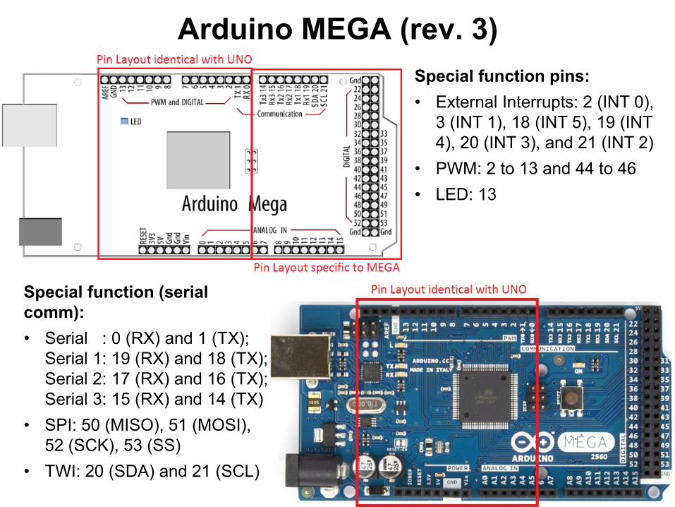
Arduino MEGA (rev. 3)
Special function (serial
comm):
• Serial : 0 (RX) and 1 (TX);
Serial 1: 19 (RX) and 18 (TX);
Serial 2: 17 (RX) and 16 (TX);
Serial 3: 15 (RX) and 14 (TX)
• SPI: 50 (MISO), 51 (MOSI),
52 (SCK), 53 (SS)
• TWI: 20 (SDA) and 21 (SCL)
Special function pins:
• External Interrupts: 2 (INT 0),
3 (INT 1), 18 (INT 5), 19 (INT
4), 20 (INT 3), and 21 (INT 2)
• PWM: 2 to 13 and 44 to 46
• LED: 13
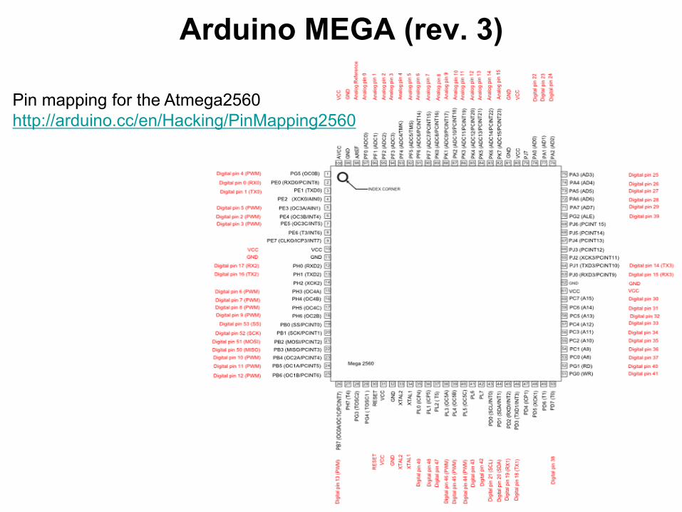
Arduino MEGA (rev. 3)
Pin mapping for the Atmega2560
http://arduino.cc/en/Hacking/PinMapping2560
The programming environment performs the PIN correspondence / mapping
The programming logic is PIN-number oriented
Digital I/O
•can be programed as an input or output, using pinMode()
•can be accessed as an input/output with digitalWrite(), and digitalRead() functions
•operate at 5 volts / can provide or receive a maximum of 40 mA
•an internal pull-up resistor (disconnected by default) of 20-50 kOhms
•some pins can have specialized functions ….
Analogue I/O
•read an analogue value (input): analogRead()
•generate a PWM signal (output): analogWrite() - PWM
•configure the reference voltage used for analog input - analogReference()
http://arduino.cc/en/Reference/HomePage
Input / output for Arduino systems

Example 1:
• Input: BTN connected to a digital pin
• Use of an explicit/external “pull down” resistor (BTN not pressed: input – “0”)
• Output: on-board LED (shared with pin 13)
Input / output for Arduino systems

Example 1:
Input / output for Arduino systems
Alternative code:

Example 2:
• Input from a switch (no external resistor)
• Internal ‘Pull-Up’ logic of each pin is used (enabled)
Input / output for Arduino systems

Example 3: reading of unstable data (i.e. buttons without internal de-bounce logic
http://www.robofun.ro/bricks/buton-mare-brick )
•A mechanical contact can oscillate (bounce) between close and open state several
times until reaches a stable state
•A mC is fast enough to ‘sense’ these oscillations – perceives them as repeated
on/off states
•The oscillations can be compensated/filtered out by software
Note: the Digilent Pmod BTN has an intrinsic/hardware de-bounce logic
implemented – no other software logic should be implemented !!!
Input / output for Arduino systems

Example 3: software de-bounce
•Filtering principle: check the input for several times until a stable level is
encountered
•Outcome: bouncing period is ignored; input value is validated only when is stable
Input / output for Arduino systems
// Time delay (ms) after which input signal should be stable

Example 4: keyboard
•Pressing one key: contact between the corresponding row and the column
•Default Row status = ‘1’ (pull-up logic enabled)
•If a key is pressed:
• If corresponding Column = ‘0’ corresponding Row = ‘0’
• Else (Column = ‘1’) nothing happens (Row = ‘1’ – pull-up logic)
Keyboard scanning principle
• Each column is activated in a sequential order (set to ‘0’). Read the status of
the rows
• Columns pins - configured as outputs. Row pins - configured as inputs
Input / output for Arduino systems

Example 4: keyboard
Input / output for Arduino systems

Example 4: keyboard
Input / output for Arduino systems

Example 4: keyboard
Input / output for Arduino systems

Used for detecting external events (without polling with digitalRead() )
External Interrupts for Arduino systems
To use an interrupt an ISR (Interrupt Service routine should be attached:
attachInterrupt(interrupt, ISR, mode)
Parameters
interrupt: the number of the interrupt (int)
ISR: the ISR to call when the interrupt occurs; this function must take no parameters and return nothing.
mode: defines when the interrupt should be triggered. Four contstants are predefined as valid values:
LOW to trigger the interrupt whenever the pin is low,
CHANGE to trigger the interrupt whenever the pin changes value
RISING to trigger when the pin goes from low to high,
FALLING for when the pin goes from high to low.
To de-attach an interrupt: detachInterrupt(interrupt_no
To deactivate all interrupts use: noInterrupts(). To reactivate all interrupts use”: interrupts().
Interrupts are activated by default! Deactivation should be done only temporary!

Example 5: toggles the status of the on-board LED when a BTN is pressed
using interrupts
int outputLED =13;
volatile int stateLED = LOW; //current status of the LED
// the setup routine runs once when you press reset:
void setup() {
pinMode(outputLED, OUTPUT);
attachInterrupt(0, isr0, RISING); // init ISR0 (pin 2) and behavior
}
void isr0()
{
stateLED = !stateLED; //on ISR togle the LED status
if (stateLED == 1)
digitalWrite(outputLED, HIGH);
else
digitalWrite(outputLED, LOW);
}
// the loop routine runs over and over again forever:
void loop() {
}
• All variables that are used in a ISR should be declared as “volatile”. The compiler will know that
these variable can be modified at any time and shall not optimize the code by attaching them to
registers, but instead will store them always into the RAM
• Only one ISR can run at a time (others are deactivated)
External Interrupts for Arduino systems

Example 6: measuring the pulse width of a digital signal (i.e. signal received
from an IR remote controller – the pulse width is ‘translated’ as a ‘0’ or a ‘1’)
External Interrupts for Arduino systems
// No. of. analyzed transitions
// No. of microseconds elapsed from program start
// Position in the transitions string
// Transitions string (contains the duration of the
transitions) - output
// Check if the max. no. of transitions is reached

External Interrupts for Arduino systemsExample 6: measuring the pulse width of a digital signal (i.e. signal received
from an IR remote controller – the pulse width is ‘translated’ as a ‘0’ or a ‘1’)
• micros() – returns the number of microseconds elapsed from program start
[millis() - returns the number of microseconds elapsed from program start]
Homework: Write the code for example 5 using the polling technique (no
interrupts)
References:
Michael Margolis, Arduino Cookbook, 2-nd Edition, O’Reilly, 2012.
Arduino documentation: http://arduino.cc/
// ISR
// If not end of transitions string
// If not first transition
// Advance the index
// Mem. current time (reference for the next transition)


