1 DESIGN THE VTOL AIRCRAFT FOR LAND SURVEYING PURPOSES SHAHDAN BIN AZMAN A report submitted as the first draft of the final year project in semester 1 2016/2017 Faculty of Mechanical Engineering Universiti Teknologi Malaysia January 2017
Transcript
1
DESIGN THE VTOL AIRCRAFT FOR LAND SURVEYING PURPOSES
SHAHDAN BIN AZMAN
A report submitted as the first draft of the final year project in semester 1 2016/2017
Faculty of Mechanical Engineering
Universiti Teknologi Malaysia
January 2017
2
1 INTRODUCTION
This chapter is the overview of the whole idea of the project. UAV’s application
in the early age of their appearance was widely been used for military purposes
especially for scouting and surveillance. Nowadays, people has implemented the
benefits of UAV into our daily life such as land surveying, aerial photography,
delivery, wildlife research, news and etc.
1.1 Background Research
1.1.1 Application of UAV in land surveying
Surveillance is one of the main objectives in most of UAV creation. Previously,
before UAV was invented, manned vehicles is implemented to carry out the operation
of monitoring the condition of the land activity such as the roadway network, vehicle
movements, land development and etc (Zaryab, 2016). Nevertheless, implementation
of manned vehicle in this operation affect the environmental issues especially the noise
produce from the helicopter and aeroplane. Besides, cost are way more expensive if
compare to latest implementation of UAV in this activity.
Therefore, UAV have been suggested in most of the land surveying operators
because of its cost effectiveness and safety to the pilot’s life. Besides, UAV especially
the small scale UAV have greater maneuverability and control in a low flight and
confined space. Nevertheless, permission of access in a prohibited flying areas is still
a main consideration in every land surveying operations in order to respect one’s
privacy of their properties
3
1.2 Problem Statement
Nowadays, the Geospatial Information System (GIS) operators used small UAV
to conduct the air-based land surveying operations. Most of the UAV used in the
operations are fixed-wing type since it has better endurance and range. The main
problems face by the operators are the difficulty to launch and land the aircraft safely
and crashes that occurred due to unexpected conditions.
The operators might have some difficulties to launch the fixed wing aircraft
especially in a limited airspace while in other hand to land safely in a limited ground
space. The UAV also had some issues due to multiple crashes because of improper
landing and uncertainty conditions during flight which lead to shorter service period.
1.3 Research Objectives
1. To design an aircraft equipped with VTOL mechanism using parametric study
2. To select suitable material and structure used for the aircraft.
3. To fabricate and test the aircraft.
1.4 Research Scopes
The scope for this research is listed below:
1. The design process of the VTOL aircraft followed the design step according to
the reference book, Aircraft Design: A Conceptual Approach by Raymer
(2006).
2. Materials selection is based on the most sustainable for the aircraft operation..
3. Simple fabrication is used to make the maintenance of the aircraft easier.
4. Manual remote control pilot system will be the main avionic system.
4
1.5 Schedule Planning
Time management during the research and design process is very important in
order to achieve specific goals. Therefore, the flow chart and Gantt chart for the design
process has been constructed in order to complete it on time given. The flow chart is
used to clearly define the targets need to be complete throughout the project. Besides
that, the Gantt chart of the project is used as a guidance to complete the task according
to a certain period. The Gantt chart of this project presented in Appendix A.
Figure 1.1: Flow chart of the project
Design and Fabrication of The VTOL UAV
Literature review
Feasibility Study
Conceptual Design
Aerodynamic Analysis
Performance Analysis
Preliminary Design
Optimization
Detail Design
Fabrication
Flight Test
5
2 LITERATURE REVIEW
2.1 RC Aircraft
Radio-controlled aircraft is a small scaled flying machine that operated by an
operator from the ground by using transmitter to send signal to the receiver installed
in the flying machine (Boddington, 1978). By using the transmitter, the operator can
control the movement of the aircraft through signal transmission to all the electronic
parts in the aircraft. Joystick in the transmitter is used to control the position of the
control surfaces of the aircraft which for typical aircraft are throttle, elevator, aileron
and rudder.
2.2 VTOL Aircraft
VTOL aircraft stands for vertical take-off landing aircraft where the aircraft has
different type of take-off and landing compare to short take-off landing. The aircraft
unnecessarily use the runway to take-off while capable to enter inaccessible areas
(Zafirov, 2013). This could justify the solution of choosing the VTOL aircraft to
operate in inaccessible areas especially places surrounded with trees.
According to Zafirov (2013), the main consideration in the VTOL aircraft
development is the thrust vector of the VTOL propulsion system which must be pass
through precisely at the maximum centre of gravity of the aircraft in order to achieve
good take-off and landing quality. In addition, the aircraft should have greater than 1
of the thrust-to-weight ratio value in order to achieve successful vertical take-off and
landing (Zafirov, 2013).
6
2.3 Aircraft Design
The design process of the VTOL aircraft follows the aircraft design process
(Abdelrahman, et al., 2009).According to Rabbey, Papon, Rumi, Monerujjaman and
Nuri (2013), the aircraft design process can be referred to many references. One of the
conservative reference is chosen which is the Aircraft Design: A Conceptual Approach
by Raymer (2006).
2.3.1 Conceptual Design
The conceptual design is where the designer put the idea of building an aircraft
based on the criteria and specified goals of the aircraft that need to be achieved. The
objective of this stage is to conceptualize the idea and to understand the basic
configurations of the aircraft. During this stage, the general airframe and sizing is
sketched and preliminary analysis is done on the designed aircraft. In order to achieve
the specification of the designed aircraft, iteration process is needed. Figure __ shows
the aircraft conceptual design process.
7
Figure 2.1: Aircraft conceptual design process (Raymer, 2006)
2.3.1.1 Aerodynamic Analysis
The aerodynamic analysis of an aircraft is very important to determine its
flying qualities. Generally, lift, drag and moment of the aircraft are the important
aerodynamic parameters of an aircraft. To determine these parameters, experimental
approach and analytical approach are available methods that can be used. Analytical
method is used to estimate the aerodynamic coefficient of the designed aircraft due to
time constrain.
Analytical approach method is done by using the XFLR5 software. The
XFLR5 software is used to estimate the aerodynamic characteristic of the aircraft
according to R/C Soaring Digest (2008). The software is a fast subsonic airplane
prototyping software where it includes the lifting theory (LLT), vortex lattice method
(VLM) and 3D panel method for aerodynamic characteristic estimation. Nevertheless,
the software has some limitation where the fuselage is excluded in the calculation due
to the accuracy of the aerodynamic characteristics affected by the fuselage integration.
8
USAF DATCOM semi-empirical method is used to estimate the aerodynamic
characteristics (Chong, 2007). Similarly, Harris (2007) employed the DATCOM
method in his thesis, Aerodynamic Study of Flow over UAV. Nonetheless, the
DATCOM is more suitable in determining aerodynamic characteristics for aircraft
with speed above Mach number of 0.3 (Harris, 2007).
In the dissertation of Master of Science by Trips (2010), the details of setting
up XFLR5 is shown and presented. Therefore, the aerodynamic analysis of the aircraft
using the XFLR5 can be approximated and estimated by referring to Trips (2010).
2.3.1.2 Performance Analysis
Preliminary performance analysis must be conducted in aircraft design process
in order to define its general performance and as well to check the efficiency of the
whole propulsion system. The performance analysis are examined through some of
the important parameters which are the power available, power required, thrust
available, thrust required, rate of climb, endurance and range. These parameter can
obtained from the analysis by referring to Aircraft Performance and Design by John
D. Anderson, Jr (1999).
2.3.2 Preliminary Design
Preliminary design is where the aircraft design will be redesign and reanalysed
without takes much changing in its original sizing and basic configurations specified
earlier (Raymer, 2006). Further precise analysis especially the structural and
performance analysis is one of the important part in preliminary design. According to
9
Zi Yang (2015), extra testing and prototyping are required in order to define the
materials, amount of materials, structure arrangement and propulsion system that will
be used in the aircraft design.
In most cases, computer aided design (CAD) is used to do the process of
reshape and reconfigure the general design perfectly and fast. In the meantime, the
fabrication procedure together with cost estimation of the whole design can be
established during the preliminary design process (Zi Yang, 2015).
The preliminary design of the VTOL aircraft follows the process of
preliminary design by Raymer (2006) since the aircraft design is simple. The aircraft
used several different material, thus the aircraft design must be simplified in order to
reduce the time constrain. CAD software such as Solidworks, AutoCAD Inventor and
etc. can be used to do the full scale modelling. Furthermore, these software provide
features to find the actual centre of gravity position and moment of inertia by giving
the material properties value into each parts that have been designed.
2.3.2.1 Accessories Selection
According to Zi Yang (2015), the accessories for a small scale aircraft are
referred to its propulsion system, servo for control surfaces and the power source
which in this project electric power is the main power source. The accessories
selection is vital since it involves the mission required by the VTOL aircraft.
Furthermore, it will cause waste of energy, waste in budget and affect the aircraft
flying behaviour if the selection is not conducted properly.
The VTOL aircraft for this project is comparable with the radio-controlled
(RC) model aircraft and mini UAV model, hence the accessories selection can be done
by referring to Boddington (1978) in RC plane model and journals by Rabbey, et al.,
10
(2013). Analysis such as the parametric study, aerodynamic and performance analysis
are vital in order to help the designer to list the detail specification of the accessories
selection required for the aircraft mission.
2.3.2.2 Material Selection
Materials selection is very important in order to sustain the aircraft shape. Most
of the materials that been used in RC aircraft are balsa wood, foam, fibre and etc.
According to Carlos (2017) in Introduction to RC Airplane Foams, the foam stiffness
is comparable to balsa wood while have a cheaper price. Nevertheless, the foams do
not have strength strong as balsa wood and low in density. Generally, designer must
take the feasibility of fabrication, mechanical properties and cost of the materials as
consideration (Boddington, 1978) in order to decide which material will be used in
each compartments.
2.3.3 Detail Design
Raymer (2006) stated that detail design process is where the production design
or fabrication process are required to be define before fabrication process takes place.
This is done in order to ensure the product which is the aircraft will be produce
accordingly to the specified design. Furthermore, it is to reduce lagging during the
period of fabrication process takes place.
The detail design of VTOL aircraft is done using Solidworks software. The
process focus on drawing the 3D model of each compartments and accessories of the
aircraft including the major and minor parts. The major part in this process is to draw
the ribs of the wing, attachment of the wing to the body and the VTOL motor position.
11
The procedures of the fabrication process of the RC aircraft can be done by referring
to Boddington (1978) in Building & Flying Radio Controlled Model Aircraft.
2.4 Fabrication Method
Every completed and inspected aircraft design can proceed to fabrication process
to transform the idea poured in the design stage into a real aircraft by following the
planned procedure. The difficulty of the fabrication stage is depend on the aircraft
design itself. Therefore, it is very important to double check the design in order to
avoid difficulties in fabrication stage which can lead to time constraint.
The VTOL aircraft concept is comparable to the RC aircraft model, hence the
fabrication method can be done by referring to Boddington (1978) in Building &
Flying Radio Controlled Model Aircraft. It is a good practice to choose easy
fabrication process in order for one to do the aircraft maintenance easily and
legitimate.
12
3 METHODOLOGY
3.1 Flow Chart
Generally, the project flow and the methodology will be discussed accordingly
to the flow chart as shown in figure below. The first semester of the project focused
more on study and analysis which will cover from literature review until static stability
analysis. The rest of the scope will be cover on the second semester which will focused
more on fabrication, further analysis and flight test.
13
Figure 3.1: Categorised flow chart
Design and Fabrication of The VTOL UAV
Literature review
- Parametric study
- UAV operation system
Conceptual Design
-Weight estimation
-Airfoil selection
-Preliminary sizing
-Materials selection
-Centre of gravity
-Aerodynamic analysis
-Preliminary performance
Optimization
Preliminary Design
-Modelling
Detail Design
-Final model defined
-Fabrication procedure
Flight Test
14
3.2 Literature Review
The goals for this project is to build a UAV that can fly and operate properly.
Therefore, the design process of an UAV must be referred to published books, articles
and journals as a guidance in order to achieve specified research scopes and to come
up with good justification for any decisions that have been made. The conceptual
design, fundamental analysis of a UAV are obtained from similar paper that discuss
related topic while the fabrication method, procedure and process guidelines are learnt
from the handbook and the experienced. Furthermore, related on board control system
of the UAV is studied through the journals. Besides that, the method to determine the
aerodynamic characteristics and the preliminary performance of the UAV are referred
on the thesis from university and published books.
3.3 Conceptual Design
The whole conceptual idea and design of the UAV are conducted according to
the reference book, Aircraft Design: A Conceptual Approach by Raymer (2006). The
fundamental steps and procedure of the aircraft design process are listed in the
mentioned earlier book. Basically, it consists of feasibility study, preliminary weight
estimation, preliminary sizing, aerodynamic analysis, performance and stability
analysis which will be conducted in this project.
3.3.1 Feasibility Study
Feasibility study is vital in the preliminary conceptual design. This study is a
guidance for the aircraft designer to assume the initial specification based on existed
aircraft under the same category. Hence, the first assumption is not totally accurate.
15
Feasibility study can be carried out by performing the parametric study. Table below
shows the design specification for a VTOL UAV.
Table 3.1 : Design specification and criteria
Specification and criteria Description
Wing configuration Fixed wing
Tail configuration Conventional
Weight Less than 3kg
Range 5 km
Endurance 70 min
Propulsion Electric motor
From the parametric study, some parameters are analysed graphically for initial
assumption. The data obtained is presented in Appendix B1. The considerations that
were taken in the graphs are listed as below.
1. Wing Span vs Maximum Take-off Weight (Appendix B2)
2. Fuselage Length vs Maximum Take-off Weight (Appendix B3)
3. Endurance vs Maximum Take-off Weight (Appendix B4)
4. Empty Weight vs Maximum Take-off Weight(Appendix B5)
5. Payload vs Maximum Take-off Weight (Appendix B6)
6. Power vs Maximum Take-off Weight (Appendix B7)
7. Endurance vs Maximum Take-off Weight (Appendix B8)
8. Cruising speed vs Maximum Take-off Weight (Appendix B9)
3.3.2 Weight Estimation
In Raymer (2006), the preliminary weight estimation can be obtained by using
the equation below
16
𝑊0 = 𝑊𝑐𝑟𝑒𝑤 + 𝑊𝑝𝑎𝑦𝑙𝑜𝑎𝑑 + 𝑊𝑓𝑢𝑒𝑙 + 𝑊𝑒𝑚𝑝𝑡𝑦 (1)
Since the propulsion system for the VTOL UAV is electric motor, hence, we
could modified the equation (1) by removing all the unnecessary term such as weight
of the crew and fuel. Then, the equation (1) becomes
𝑊0 = 𝑊𝑝𝑎𝑦𝑙𝑜𝑎𝑑 + 𝑊𝑒𝑚𝑝𝑡𝑦 (2)
Before that, we can determine the relationship between gross weight, 𝑊0 and
payload weight 𝑊𝑝𝑎𝑦𝑙𝑜𝑎𝑑 if we could obtain the value of 𝑊𝑒𝑚𝑝𝑡𝑦
𝑊0. Hence, we could
modified equation (2) into equation (3) shown below
𝑊0 =𝑊𝑝𝑎𝑦𝑙𝑜𝑎𝑑
1−𝑊𝑒𝑚𝑝𝑡𝑦
𝑊0
(3)
The value of 𝑊𝑒𝑚𝑝𝑡𝑦
𝑊0 can be obtained from plotting Graph of Empty Weight,
versus Total Gross Weight which the graph is shown in Appendix B2. This lead to
equation below
𝑊0 = 1.02𝑊𝑝𝑎𝑦𝑙𝑜𝑎𝑑 + 1712.9 (4)
Other than that, we could determine the maximum take-off weight by
examining the wing span of the existing UAV which could be observe from the
relationship in plotted graph between maximum take-off weight and the wing span.
This lead to equation below
17
𝑆𝑤 = 10.25𝑊0 − 14264 (5)
3.3.3 Preliminary Sizing
The preliminary sizing of an aircraft can be done through scaling and
estimation of each parts required according to Raymer (2006). Generally, all of the
geometry for wing, fuselage, tail and control surfaces is estimated.
3.3.3.1 Wing Sizing
Two parameters that are important for the wing sizing of an aircraft which are
the wing chord and the wing span. These two parameters can be used to find the aspect
ratio of the aircraft. There are no specific aspect ratio requirement for a typical but the
lower and high aspect ratio are for high speed and low speed aircraft respectively. It
is recommended to determine the wing chord and wing span of the aircraft by refer to
the parametric study of the existing aircraft. The relationship of these two parameters
can be shown through these two equations below:
𝐴𝑅𝑤 =𝑤𝑖𝑛𝑔𝑠𝑝𝑎𝑛
𝑤𝑖𝑛𝑔 𝑐ℎ𝑜𝑟𝑑=
𝑏𝑤
𝑐𝑤 𝑜𝑟
(𝑤𝑖𝑛𝑔𝑠𝑝𝑎𝑛)2
𝑤𝑖𝑛𝑔 𝑎𝑟𝑒𝑎=
𝑏𝑤2
𝑆𝑤 (6)
𝑆𝑤 = 𝑏𝑤𝑐�̅� (7)
3.3.3.2 Fuselage sizing
18
The fuselage length estimation for the aircraft can either follow the parametric
study or Raymer (2006). It is preferable to use the parametric study to do the
estimation since this aircraft dimension is adapted from existed aircraft. From the
graph of fuselage sizing versus the maximum take-off weight, the equation below
shows the relationship between these two parameters.
𝐿𝑓𝑢𝑠𝑒𝑙𝑎𝑔𝑒 = 𝑚𝑊𝑀𝑇𝑂𝑊 + 𝑐 (8)
Referring to Raymer (2006), the fuselage length of the aircraft can be
approximated using the equation below.
𝐿𝑓𝑢𝑠𝑒𝑙𝑎𝑔𝑒 = 0.71(𝑊𝑀𝑇𝑂𝑊)0.48 (9)
3.3.3.3 Tail sizing
There are many variations of tail configurations that can be implemented on
the aircraft design. Some of the examples are shown in the Figure below.
Figure 3.2 : Basic tail configuration of an aircraft (Raymer, 2006)
19
Generally the tail sizing can be estimated using tail volume coefficient
(Raymer, 2006) and equation shows the vertical tail volume coefficient and equation
shows the horizontal tail volume coefficient.
𝑉𝑣𝑡 =𝐿𝑣𝑡𝑆𝑣𝑡
𝑏𝑤𝑆𝑤 (10)
𝑉ℎ𝑡 =𝐿𝑣𝑡𝑆𝑣𝑡
𝑏𝑤𝑆𝑤 (11)
Otherwise, the tail volume coefficient also can be approximated according to
Table 3.2 below
Table 3.2 : Tail volume coeffcient
Type of aircraft Horizontal 𝑉ℎ𝑡 Vertical 𝑉𝑣𝑡
Homebuilt 0.5 0.04
General Aviation – single
engine
0.7 0.04
By using the relationship of the tail volume coefficient, the tail area can be
computed. According to Corke (2003), the root chord and tip chord for both horizontal
and vertical tail can be estimated according to the tail aspect ratio and taper ratio.
Besides that, by using the Table 3.3 the aft tail aspect ratio and taper ratio can be
estimated according to Raymer (2006).
Table 3.3 :Tail arm length
Aft horizontal tail Aft vertical tail
Aspect ratio,
𝐴𝑅ℎ𝑡
Taper ratio,
𝜆ℎ𝑡
Aspect ratio,
𝐴𝑅𝑣𝑡
Taper ratio,
𝜆𝑣𝑡
Combat 3-4 0.2-0.4 0.6-1.4 0.2-0.4
Sailplane 6-10 0.3-0.5 1.5-2.0 0.4-0.6
20
Other 3-5 0.3-0.6 1.3-2.0 0.3-0.6
T-tail - - 0.7-1.2 0.6-1.0
The tail root chord, tail tip chord, tail aspect ratio and tail taper ratio can be
computed using equations from (12) to (17) .
For horizontal tail,
𝐴𝑅ℎ𝑡 =𝑏ℎ𝑡
2
𝑆ℎ𝑡 (12)
𝑐𝑟ℎ𝑡= 𝜆ℎ𝑡𝑐𝑡ℎ𝑡
(13)
𝑐𝑟ℎ𝑡=
2𝑆ℎ𝑡
𝑏ℎ𝑡(1+𝜆ℎ𝑡) (14)
For vertical tail,
𝐴𝑅𝑣𝑡 =𝑏𝑣𝑡
2
𝑆𝑣𝑡 (15)
𝑐𝑟𝑣𝑡= 𝜆𝑣𝑡𝑐𝑡𝑣𝑡
(16)
𝑐𝑟𝑣𝑡=
2𝑆𝑣𝑡
𝑏𝑣𝑡(1+𝜆𝑣𝑡) (17)
3.3.3.4 Control surfaces
Basically, there are three types of control surfaces used by a typical aircraft
which are the aileron, elevator and rudder. These control will control the longitudinal,
lateral and directional stability of the aircraft and also will define the maneuverability
of the aircraft.
21
According to Raymer (2006), the aileron is used to control the rolling
behaviour of an aircraft and usually the aileron span will extend about 50% to 90% of
the wing span and aileron chord extend from 15% to 25% of the wing chord. Figure
below shows the aileron sizing guideline.
Figure 3.3 : Aileron guideline (Raymer, 2006)
In the other hand, elevator and rudder will control the pitching and yawing
behaviour of an aircraft respectively. The elevator and rudder span extend from the
tail root up to 90% of the tail span while both of these control surfaces chord cover
25% to 50% of the tail chord (Raymer, 2006).
3.3.4 Airfoil Selection
In order for an aircraft to glide during unpowered flight especially during
emergency cases, it is vital to select suitable airfoil nomenclature in order for the wing
to produce enough lift. UIUC airfoil coordinate database has big collection of airfoil
22
sample that could practically be use. One of the main consideration in the airfoil
selection of this project is the limitation of the fabrication process since it will mostly
hand made.
Perfect shape of airfoil may not be achieve if no advanced equipment are used.
Hence, an approximated method will be utilised. The characteristic of the selected
airfoil could be approximated by conducting the aerodynamic analysis using XFLR5
software. Results obtained for both airfoils are compared.
3.3.5 Materials Selection
Basically, most of the RC hobbyist will prefer use foam as it is low in density
while have good shock absorption. Two common materials that are used to
manufacture small RC aircraft are foam and balsa wood according to Boddington
(1978). Otherwise, it also can be estimated based on parametric study and handbook
by Boddington (1978).
3.3.6 Accessories Selection
In general, accessories are referring to the propulsion system, control surfaces
actuators and power source (Zi Yang, 2015). Nowadays, electrical motor is used as
main propulsion system and electrical servo is used as the control surfaces actuators
(Rabbey et al., 2013). It is recommended to survey on available accessories in the
market by examining their datasheet provide by their manufacturers to be used for
parametric study and preliminary performance analysis.
23
3.3.7 Preliminary Centre of Gravity and Moment of Inertia Estimation
Approximation of the centre of gravity can be conducted by using the
Solidworks software by giving specific density of the materials that will be used during
the modelling process. Modelling included all the accessories such as the propulsion
system and control surfaces actuators. The VTOL position is vital in the cg
management in order to reduce chances of instability during take-off.
3.3.8 Aerodynamic Analysis
For preliminary aerodynamic analysis, XFLR5 software are used since it is
suitable for an aircraft that operates at low Reynold number. XFLR5 could provide the
aerodynamic characteristics of the designed wing and tail with less computing time.
Besides, we could also find the reference velocity at particular angle of attack
while consider the aircraft will cruise under steady flight using equation (18).
𝑉∞ = √𝑊0
1
2𝜌𝑆𝑤𝐶𝐿
(18)
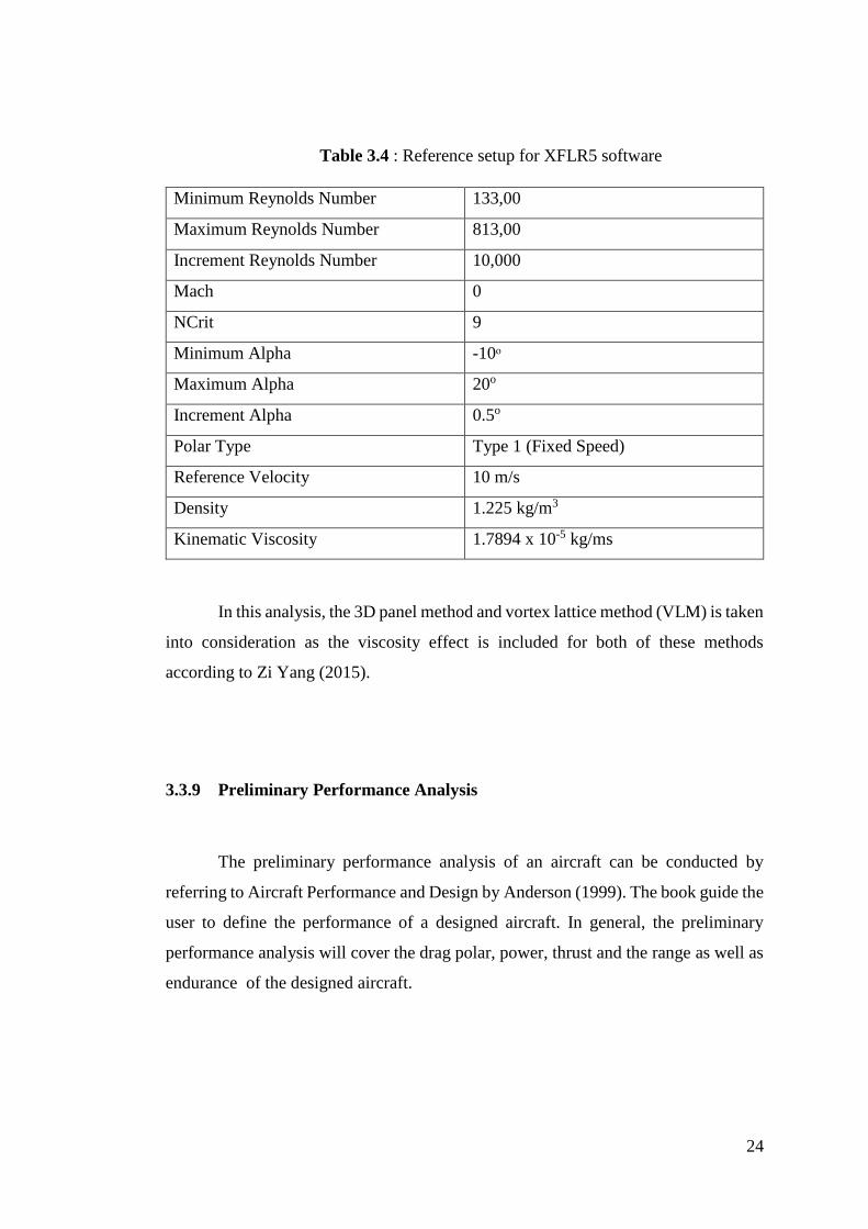
3.3.8.1 XFLR5
The steps and procedures of the XFLR5 software can be found in its official
website (Deperrois, 2012). The airfoil shape which is saved in .dat file is imported into
the software. Based on selected range of Reynolds numbers, airfoil’s aerodynamic
characteristics are approximated. Then, finite wing is inserted to find its aerodynamic
characteristics by selecting Fixed Speed configurations. Steps are repeated for tail
aerodynamic analysis. Basic setup is referred to Deperrois (2002) as listed in Table
below.
24
Table 3.4 : Reference setup for XFLR5 software
Minimum Reynolds Number 133,00
Maximum Reynolds Number 813,00
Increment Reynolds Number 10,000
Mach 0
NCrit 9
Minimum Alpha -10ᵒ
Maximum Alpha 20o
Increment Alpha 0.5o
Polar Type Type 1 (Fixed Speed)
Reference Velocity 10 m/s
Density 1.225 kg/m3
Kinematic Viscosity 1.7894 x 10⁻⁵ kg/ms
In this analysis, the 3D panel method and vortex lattice method (VLM) is taken
into consideration as the viscosity effect is included for both of these methods
according to Zi Yang (2015).
3.3.9 Preliminary Performance Analysis
The preliminary performance analysis of an aircraft can be conducted by
referring to Aircraft Performance and Design by Anderson (1999). The book guide the
user to define the performance of a designed aircraft. In general, the preliminary
performance analysis will cover the drag polar, power, thrust and the range as well as
endurance of the designed aircraft.
25
3.3.9.1 Drag Polar
Most of the aircraft designers will likely to use the drag polar of an aircraft to
determine the performance characteristic and flying qualities of an aircraft. The drag
polar describe the relationship between the total lift coefficient and total drag
coefficient of an aircraft. The drag polar can be used to calculate the lift to drag ratio
and zero lift drag coefficient.
3.3.9.2 Power Available and Required
Power available is referred to the power produced by the propulsion system
with its specific efficiency of the aircraft. According to Rabbey et. al (2013), the
aircraft is comparable to the latest mini UAV which powered by electrical motor.
Basically, the power available will not be the same with the power output of the motor
as each motor will have its own different efficiency which mostly affected by the
propeller that been used. The equation below shows the relationship between the
power available and power output of the motor.
𝑃𝑎 = 𝜂𝑝𝑟𝑜𝑝𝑃0 (19)
The performance of the electric motor could be done by using the MotoCalc
software. By using the software, we could approximate the motor performance based
on the percentage of throttle power applied, aircraft flying velocity, electric motor
controller used and the battery source. Figure 3.4 and 3.5 shows the graphical user
interface for MotoCalc software.
26
Figure 3.4 : XFLR5 interface for motor performance
Figure 3.5 : XFLR5 interface for motor performance graph analysis
Yew C. P. (2009) stated that the propeller characteristic does play an important
role in determining the actual power available, 𝑃𝑎 . Therefore, it is important to study
the propeller characteristic in order to approximate the propeller efficiency, 𝜂𝑝𝑟𝑜𝑝. By
referring to UIUC Propeller Database (2017), the propeller efficiency, 𝜂𝑝𝑟𝑜𝑝 could be
obtained.
27
Power required is referring to the power required for an aircraft to fly at certain
airspeed with its total drag force. In general, cruising is the common state taken as the
consideration in the analysis. The total power required will divided into two parts
which are the power to overcome parasite drag and power to overcome induced drag.
The equations are shown below.
Total drag,
𝐶𝐷 = 𝐶𝐷,0 + 𝐶𝐷,𝑖 (20)
Power required to overcome parasite drag,
𝑃𝑅,0 = (1
2𝜌𝑉∞
2𝑆𝑤𝐶𝐷,0) 𝑉∞ (21)
Power required to overcome induced drag,
𝑃𝑅,𝑖 = (1
2𝜌𝑉∞
2𝑆𝑤𝐶𝐷,𝑖) 𝑉∞ (22)
Total power required,
𝑃𝑅 = 𝑃𝑅,0 + 𝑃𝑅,𝑖 (23)
The induced drag coefficient is in a function of lift coefficient (Anderson,
1999) which the relation shown as below,
𝐶𝐷,𝑖 =𝐶𝐿
2
𝜋𝑒𝐴𝑅𝑤 (24)
28
3.3.9.3 Thrust Available and Required
Thrust available is the ability for the propulsion system to produce forward
thrust. Thrust is a function of power and the aircraft velocity, thus the thrust available
can be obtained if we are using the power available value by
𝑇𝑎 =𝑃𝑎
𝑉∞ (25)
Similarly, the total thrust required is a combination of force to overcome
parasite drag and force to overcome induced drag. The equations are given by
Thrust required to overcome parasite drag,
𝑇𝑅,0 =1
2𝜌𝑉∞
2𝑆𝑤𝐶𝐷,0 =𝑃𝑅,0
𝑉∞ (26)
Thrust required to overcome induced drag,
𝑇𝑅,𝑖 =1
2𝜌𝑉∞
2𝑆𝑤𝐶𝐷,𝑖 =𝑃𝑅,𝑖
𝑉∞ (27)
Total Thrust required,
𝑇𝑅 = 𝑇𝑅,0 + 𝑇𝑅,𝑖=𝑃𝑅
𝑉 (28)
29
3.3.9.4 Range
Range is the distance travel by the aircraft with such amount of power supplied.
The range for electrical propulsion system can be obtain by using the Breguet equation
(Anderson, 2009) which derived as shown in equations (29) and (30)
𝑅 = 3.6𝜂𝑠𝑦𝑠 (𝐶𝐿
𝐶𝐷)
𝑈𝑒𝑙(Δ𝐶𝑒𝑙)
𝑊𝑜 (29)
Maximum range is given by
𝑅 = 3.6𝜂𝑠𝑦𝑠 (𝐶𝐿
𝐶𝐷)
𝑚𝑎𝑥
𝑈𝑒𝑙(Δ𝐶𝑒𝑙)
𝑊𝑜 (30)
Where 𝑅 and 𝑅𝑚𝑎𝑥 unit is in km
The electric power supplied is consider not totally supplied the whole
propulsion system as it also supplied to another subsystem. Therefore, the range
equation can be derive as shown in equation (31) and (32).
𝑅 = 3.6(Δ𝐶𝑒𝑙)
(𝐶𝐿𝐶𝐷
)𝑤
𝜂𝑠𝑦𝑠𝑈𝑒𝑙+
𝐼𝑒𝑙𝑠𝑢𝑏𝑉∞
(31)
While maximum range could be written as
30
𝑅𝑚𝑎𝑥 = 3.6(Δ𝐶𝑒𝑙)
(𝐶𝐿𝐶𝐷
)𝑚𝑎𝑥
𝑤
𝜂𝑠𝑦𝑠𝑈𝑒𝑙+
𝐼𝑒𝑙𝑠𝑢𝑏𝑉∞
(32)
Where 𝑅 and 𝑅𝑚𝑎𝑥 unit is in km
3.3.9.5 Endurance
Endurance of an aircraft is about how long it will stay in its flight with given
power supplied. Similarly, with the same approach the derivation for endurance could
be written as
𝐸 = 60√(𝐶𝐿
3
𝐶𝐷2) √
𝑆𝑤𝜌
2𝑊𝑂3 𝜂𝑠𝑦𝑠𝑈𝑒𝑙(Δ𝐶𝑒𝑙) (33)
While maximum endurance is given by
𝐸𝑚𝑎𝑥 = 60√(𝐶𝐿
3
𝐶𝐷2)
𝑚𝑎𝑥√
𝑆𝑤𝜌
2𝑊𝑂3 𝜂𝑠𝑦𝑠𝑈𝑒𝑙(Δ𝐶𝑒𝑙) (34)
Where 𝐸 and 𝐸𝑚𝑎𝑥 unit is in minutes
Previously, using the same consideration in determine range equation, the
endurance equation could be written as
31
𝐸 = 60𝜂𝑠𝑦𝑠𝑈𝑒𝑙(Δ𝐶𝑒𝑙)
{√(1/(𝐶𝐿
3
𝐶𝐷2))
2𝑊𝑂3
𝑆𝑤𝜌}+𝜂𝑠𝑦𝑠𝑈𝑒𝑙𝐼𝑒𝑙𝑠𝑢𝑏
(35)
While maximum endurance is given by
𝐸 = 60𝜂𝑠𝑦𝑠𝑈𝑒𝑙(Δ𝐶𝑒𝑙)
{√(1/(𝐶𝐿
3
𝐶𝐷2)
𝑚𝑎𝑥
)2𝑊𝑂
3
𝑆𝑤𝜌}+𝜂𝑠𝑦𝑠𝑈𝑒𝑙𝐼𝑒𝑙𝑠𝑢𝑏
(36)
Where 𝐸 and 𝐸𝑚𝑎𝑥 unit is in minutes
3.4 Optimization
According to Zi Yang (2015), the aircraft design is required to be optimised in
order to achieve the best configuration with the desired performance specification after
all the preliminary analysis done. The optimization can be divided into several parts
which are the sizing can be referring to Raymer (2006), and the stability to Anderson
(1999) and Nelson (1998).
32
3.5 Preliminary Design, Detail Design and Fabrication
Preliminary design can be proceeded when the optimization done. Modelling of
the aircraft can be conducted by using Solidworks software by including all of the
accessories required. Fabrication procedure is established when the modelling process
is completed where the methods and steps to fabricate the aircraft will be listed.
According to Boddington (1978), the process is called as detail design. The procedure
to fabricate the aircraft is listed in Appendix. The items and materials required is listed
in Appendix D.
3.6 Validation Works and Flight Test
Finally, the aircraft flying qualities especially the VTOL mechanisms will be
conducted by using the radio telemetry. Manual mode will be used during the flight
test and no stabilization mode is used since there is no augmentation system will be


![[MS-AZMP]: Authorization Manager (AzMan) Policy File Format... · the Microsoft Authorization Manager (AzMan) policy. AzMan policy files are typically used in two ways: 1. Loaded](https://static.documents.pub/doc/80x56/5fa59701e400b433fe529e07/ms-azmp-authorization-manager-azman-policy-file-format-the-microsoft.jpg)


