Project Number: Design Verification Test Tracking Code: TC1002—3030_Report_Rev_1 Requested by: Brandon Harpenau Date: 2/20/2014 Product Rev: 2 Part #: SPM-05-S-B-RA-PF / USBC-MA-MB-B-S-S-1-R Lot #: 1 Tech: Troy Cook Tony Wagoner Aaron McKim Eng: Eric Mings Mark Shireman Part description: Sealed Port Mini USB Qty to test: 65 Test Start: 01/07/2010 Test Completed: 4/2/2010 Page 1 of 36 Design Verification Test Report PART DESCRIPTION SPM-05-S-B-RA-PF / USBC-MA-MB-B-S-S-1-R
Transcript
Project Number: Design Verification Test Tracking Code: TC1002—3030_Report_Rev_1
01 Dust Test Dust Test w/ DCSPM-01 Submersion Water Test Stream of Water Test
02 Check for Dust Check for Dust Check for Water Check for Water
Dust/Water Testing = Per CEI/IEC 60529 Code IP67
Dust/Water Testing = Per CEI/IEC 60529 Code IP66
*Torque spec on DCN-1532-32 shoud be 2.5 in-lb min.
Tracking Code: TC1002—3030_Report_Rev_1 Part #: SPM-05-S-B-RA-PF / USBC-MA-MB-B-S-S-1-R
Part description: Sealed Port Mini USB
Page 6 of 36
ATTRIBUTE DEFINITIONS The following is a brief, simplified description of attributes.
THERMAL: 1) EIA-364-17, Temperature Life with or without Electrical Load Test Procedure for Electrical Connectors.
2) Test Condition 4 at 105° C.
3) Test Time Condition B for 250 hours.
4) All test samples are pre-conditioned at ambient.
5) All test samples are exposed to environmental stressing in the mated condition.
HUMIDITY: 1) Reference document: EIA-364-31, Humidity Test Procedure for Electrical Connectors.
2) Test Condition B, 240 Hours.
3) Method III, +25° C to + 65° C, 90% to 98% Relative Humidity excluding sub-cycles 7a and 7b.
4) All samples are pre-conditioned at ambient.
5) All test samples are exposed to environmental stressing in the mated condition.
TEMPERATURE RISE (Current Carrying Capacity, CCC): 1) EIA-364-70, Temperature Rise versus Current Test Procedure for Electrical Connectors and Sockets.
2) When current passes through a contact, the temperature of the contact increases as a result of I2R (resistive)
heating.
3) The number of contacts being investigated plays a significant part in power dissipation and therefore
temperature rise.
4) The size of the temperature probe can affect the measured temperature.
5) Copper traces on PC boards will contribute to temperature rise:
a. Self heating (resistive)
b. Reduction in heat sink capacity affecting the heated contacts
6) A de-rating curve, usually 20%, is calculated.
7) Calculated de-rated currents at three temperature points are reported:
a. Ambient
b. 80о C
c. 95о C
d. 115о C
8) Typically, neighboring contacts (in close proximity to maximize heat build up) are energized.
9) The thermocouple (or temperature measuring probe) will be positioned at a location to sense the maximum
temperature in the vicinity of the heat generation area.
10) A computer program, TR 803.exe, ensures accurate stability for data acquisition.
11) Hook-up wire cross section is larger than the cross section of any connector leads/PC board traces, jumpers,
etc.
12) Hook-up wire length is longer than the minimum specified in the referencing standard.
CONTACT GAPS: 1) Gaps above the surrounding plastic surface were measured before and after stressing the contacts (e.g.
thermal aging, mechanical cycling, etc.).
2) Typically, all contacts on the connector are measured.
Tracking Code: TC1002—3030_Report_Rev_1 Part #: SPM-05-S-B-RA-PF / USBC-MA-MB-B-S-S-1-R
Part description: Sealed Port Mini USB
Page 7 of 36
MATING/UNMATING: 1) Reference document: EIA-364-13, Mating and Unmating Forces Test Procedure for Electrical Connectors.
2) The full insertion position was to within 0.003” to 0.004” of the plug bottoming out in the receptacle to
prevent damage to the system under test.
3) One of the mating parts is secured to a floating X-Y table to prevent damage during cycling.
NORMAL FORCE (FOR CONTACTS TESTED IN THE HOUSING): 1) Reference document: EIA-364-04, Normal Force Test Procedure for Electrical Connectors.
2) The contacts shall be tested in the connector housing.
3) If necessary, a “window” shall be made in the connector body to allow a probe to engage and deflect the
contact at the same attitude and distance (plus 0.05 mm [0.002”]) as would occur in actual use.
4) The connector housing shall be placed in a holding fixture that does not interfere with or otherwise influence
the contact force or deflection.
5) Said holding fixture shall be mounted on a floating, adjustable, X-Y table on the base of the Dillon TC2,
computer controlled test stand with a deflection measurement system accuracy of 5.0 µm (0.0002”).
6) The nominal deflection rate shall be 5 mm (0.2”)/minute.
7) Unless otherwise noted a minimum of five contacts shall be tested.
8) The force/deflection characteristic to load and unload each contact shall be repeated five times.
9) The system shall utilize the TC2 software in order to acquire and record the test data.
10) The permanent set of each contact shall be measured within the TC2 software.
11) The acquired data shall be graphed with the deflection data on the X-axis and the force data on the Y-axis
and a print out will be stored with the Tracking Code paperwork.
INSULATION RESISTANCE (IR): To determine the resistance of insulation materials to leakage of current through or on the surface of these
materials when a DC potential is applied.
1) PROCEDURE:
a. Reference document: EIA-364-21, Insulation Resistance Test Procedure for Electrical Connectors.
b. Test Conditions:
i. Between Adjacent Contacts or Signal-to-Ground
ii. Electrification Time 2.0 minutes
iii. Test Voltage (500 VDC) corresponds to calibration settings for measuring resistances.
2) MEASUREMENTS:
3) When the specified test voltage is applied (VDC), the insulation resistance shall not be less than 5000
megohms.
Tracking Code: TC1002—3030_Report_Rev_1 Part #: SPM-05-S-B-RA-PF / USBC-MA-MB-B-S-S-1-R
Part description: Sealed Port Mini USB
Page 8 of 36
DIELECTRIC WITHSTANDING VOLTAGE (DWV): To determine if the sockets can operate at its rated voltage and withstand momentary over potentials due to
switching, surges, and other similar phenomenon. Separate samples are used to evaluate the effect of
environmental stresses so not to influence the readings from arcing that occurs during the measurement
process.
1) PROCEDURE:
a. Reference document: EIA-364-20, Withstanding Voltage Test Procedure for Electrical Connectors.
b. Test Conditions:
i. Between Adjacent Contacts or Signal-to-Ground
ii. Barometric Test Condition 1
iii. Rate of Application 500 V/Sec
iv. Test Voltage (VAC) until breakdown occurs
2) MEASUREMENTS/CALCULATIONS
a. The breakdown voltage shall be measured and recorded.
b. The dielectric withstanding voltage shall be recorded as 75% of the minimum breakdown voltage.
c. The working voltage shall be recorded as one-third (1/3) of the dielectric withstanding voltage (one-
fourth of the breakdown voltage).
LLCR: 1) EIA-364-23, Low Level Contact Resistance Test Procedure for Electrical Connectors and Sockets.
2) A computer program, LLCR 221.exe, ensures repeatability for data acquisition.
3) The following guidelines are used to categorize the changes in LLCR as a result from stressing
a. <= +5.0 mOhms: ----------------------------- Stable
b. +5.1 to +10.0 mOhms: ---------------------- Minor
c. +10.1 to +15.0 mOhms: -------------------- Acceptable
d. +15.1 to +50.0 mOhms: -------------------- Marginal
e. +50.1 to +2000 mOhms: ------------------- Unstable
f. >+2000 mOhms: ----------------------------- Open Failure
Tracking Code: TC1002—3030_Report_Rev_1 Part #: SPM-05-S-B-RA-PF / USBC-MA-MB-B-S-S-1-R
Part description: Sealed Port Mini USB
Page 9 of 36
GAS TIGHT: To provide method for evaluating the ability of the contacting surfaces in preventing penetration of harsh
vapors which might lead to oxide formation that may degrade the electrical performance of the contact
system.
1) EIA-364-23, Low Level Contact Resistance Test Procedure for Electrical Connectors and Sockets.
2) A computer program, LLCR 221.exe, ensures repeatability for data acquisition.
3) The following guidelines are used to categorize the changes in LLCR as a result from stressing
a. <= +5.0 mOhms: ----------------------------- Stable
b. +5.1 to +10.0 mOhms: ---------------------- Minor
c. +10.1 to +15.0 mOhms: -------------------- Acceptable
d. +15.1 to +50.0 mOhms: -------------------- Marginal
e. +50.1 to +2000 mOhms: ------------------- Unstable
f. >+2000 mOhms: ----------------------------- Open Failure
4) Procedure:
a. Reference document: EIA-364-36, Test Procedure for Determination of Gas-Tight Characteristics
for Electrical Connectors, Sockets and/or Contact Systems.
b. Test Conditions:
i. Class II--- Mated pairs of contacts assembled to their plastic housings.
ii. Reagent grade Nitric Acid shall be used of sufficient volume to saturate the test chamber
iii. The ratio of the volume of the test chamber to the surface area of the acid shall be 10:1.
iv. The chamber shall be saturated with the vapor for at least 15 minutes before samples are
added.
v. Exposure time, 55 to 65 minutes.
vi. The samples shall be no closer to the chamber walls than 1 inches and no closer to the
surface of the acid than 3 inches.
vii. The samples shall be dried after exposure for a minimum of 1 hour.
viii. Drying temperature 50о C
ix. The final LLCR shall be conducted within 1 hour after drying.
SUPPLEMENTAL TESTS
WATER TESTING: 1) Reference document: CEI/IEC 60529 Code IP66 and IP67
2) Torque requirements for testing:
a. DCN-1532-32: 2.5 Inch/Lb Min.
b. Machine Screw Torque to Fixture: 15.0 Inch/Lb Min.
Tracking Code: TC1002—3030_Report_Rev_1 Part #: SPM-05-S-B-RA-PF / USBC-MA-MB-B-S-S-1-R
Part description: Sealed Port Mini USB
Page 13 of 36
LLCR Durability (32 LLCR test points) – 1000 Cycles
Initial --------------------------------------------------------------- 47.4 mOhms Max
Durability, 1000 Cycles
o <= +5.0 mOhms ------------------------------------ 26 Points ------------------------- Stable
o +5.1 to +10.0 mOhms ----------------------------------- 5 Points ------------------------- Minor
o +10.1 to +15.0 mOhms --------------------------------- 1 Points ------------------------- Acceptable
o +15.1 to +50.0 mOhms --------------------------------- 0 Points ------------------------- Marginal
o +50.1 to +2000 mOhms --------------------------------- 0 Points ------------------------- Unstable
o >+2000 mOhms ------------------------------------------ 0 Points ------------------------- Open Failure
Thermal
o <= +5.0 mOhms ------------------------------------ 27 Points ------------------------- Stable
o +5.1 to +10.0 mOhms ----------------------------------- 4 Points ------------------------- Minor
o +10.1 to +15.0 mOhms --------------------------------- 1 Points ------------------------- Acceptable
o +15.1 to +50.0 mOhms --------------------------------- 0 Points ------------------------- Marginal
o +50.1 to +2000 mOhms --------------------------------- 0 Points ------------------------- Unstable
o >+2000 mOhms ------------------------------------------ 0 Points ------------------------- Open Failure
Humidity
o <= +5.0 mOhms ------------------------------------ 29 Points ------------------------- Stable
o +5.1 to +10.0 mOhms ----------------------------------- 3 Points ------------------------- Minor
o +10.1 to +15.0 mOhms --------------------------------- 0 Points ------------------------- Acceptable
o +15.1 to +50.0 mOhms --------------------------------- 0 Points ------------------------- Marginal
o +50.1 to +2000 mOhms --------------------------------- 0 Points ------------------------- Unstable
o >+2000 mOhms ------------------------------------------ 0 Points ------------------------- Open Failure
LLCR Durability (32 LLCR test points) – 5000 Cycles
Initial --------------------------------------------------------------- 43.8 mOhms Max
Durability, 1000 Cycles
o <= +5.0 mOhms ------------------------------------ 31 Points ------------------------- Stable
o +5.1 to +10.0 mOhms ----------------------------------- 1 Points ------------------------- Minor
o +10.1 to +15.0 mOhms --------------------------------- 0 Points ------------------------- Acceptable
o +15.1 to +50.0 mOhms --------------------------------- 0 Points ------------------------- Marginal
o +50.1 to +2000 mOhms --------------------------------- 0 Points ------------------------- Unstable
o >+2000 mOhms ------------------------------------------ 0 Points ------------------------- Open Failure
LLCR Gas Tight (32 LLCR test points)
Initial --------------------------------------------------------------- 45.8 mOhms Max
Gas-Tight
o <= +5.0 mOhms ------------------------------------ 32 Points ------------------------- Stable
o +5.1 to +10.0 mOhms ----------------------------------- 0 Points ------------------------- Minor
o +10.1 to +15.0 mOhms --------------------------------- 0 Points ------------------------- Acceptable
o +15.1 to +50.0 mOhms --------------------------------- 0 Points ------------------------- Marginal
o +50.1 to +2000 mOhms --------------------------------- 0 Points ------------------------- Unstable
o >+2000 mOhms ------------------------------------------ 0 Points ------------------------- Open Failure
Tracking Code: TC1002—3030_Report_Rev_1 Part #: SPM-05-S-B-RA-PF / USBC-MA-MB-B-S-S-1-R
Part description: Sealed Port Mini USB
Page 14 of 36
SUPPLEMENTAL TESTING
IP66 & IP67 Testing w/o Mate (Water & Dust)
Initial (Before Exposure) After Exposure
Water No Water Present No Water Present
Dust No Dust Present No Dust Present
Tracking Code: TC1002—3030_Report_Rev_1 Part #: SPM-05-S-B-RA-PF / USBC-MA-MB-B-S-S-1-R
Part description: Sealed Port Mini USB
Page 15 of 36
DATA SUMMARIES
TEMPERATURE RISE (Current Carrying Capacity, CCC):
1) High quality thermocouples whose temperature slopes track one another were used for temperature
monitoring.
2) The thermocouples were placed at a location to sense the maximum temperature generated during testing. 3) Temperature readings recorded are those for which three successive readings, 15 minutes apart, differ less
than 1° C (computer controlled data acquisition).
4) Adjacent contacts were powered:
a. Linear configuration with 1 conductors/contacts powered
TC1011--3276
1 (1x1) Contacts inSeries
Part Numbers: SPM-05-S-B-RA-PF / USBC-MA-MB-B-S-S-1-R
6.76.7
5.35.3
4.24.2
3.33.33.63.6
2.92.9
2.12.1
1.61.6
0.0
1.0
2.0
3.0
4.0
5.0
6.0
7.0
20 40 60 80 100 120 140
Ambient Temperature, ° C
Maxim
um
Cu
rren
t, A
mp
per
Co
nta
ct
Base Curve
Derated 20 %
RT Peak Amp
RT Derated Amp
Measured Current
85 ° C
85 ° C Peak Amp
85 ° C Derated Amp
95 ° C
95 ° C Peak Amp
95 ° C Derated Amp
Limit
115 ° C Peak Amp
115 ° C Derated Amp
115 ° C
Room Temp
125° C
Limit
Useful Range
Room Temp= 23.8 C
Current Rating per Contact (30 Deg. Rise, 20% Derated) = 2.9 Amps
Tracking Code: TC1002—3030_Report_Rev_1 Part #: SPM-05-S-B-RA-PF / USBC-MA-MB-B-S-S-1-R
Part description: Sealed Port Mini USB
Page 16 of 36
b. Linear configuration with 2 adjacent conductors/contacts powered
TC1011--3276
2 (1x2) Contacts inSeries
Part Numbers: SPM-05-S-B-RA-PF / USBC-MA-MB-B-S-S-1-R
5.85.8
4.74.7
3.63.6
2.92.93.13.1
2.52.5
1.71.7
1.41.4
0.0
1.0
2.0
3.0
4.0
5.0
6.0
20 40 60 80 100 120 140
Ambient Temperature, ° C
Ma
xim
um
Cu
rre
nt,
Am
p p
er
Co
nta
ct
Base Curve
Derated 20 %
RT Peak Amp
RT Derated Amp
Measured Current
85 ° C
85 ° C Peak Amp
85 ° C Derated Amp
95 ° C
95 ° C Peak Amp
95 ° C Derated Amp
Limit
115 ° C Peak Amp
115 ° C Derated Amp
115 ° C
Room Temp
125° C
Limit
Useful Range
Room Temp= 24.1 C
Current Rating per Contact (30 Deg. Rise, 20% Derated) = 2.5 Amps
c. Linear configuration with 3 adjacent conductors/contacts powered
TC1011--3276
3 (1x3) Contacts inSeries
Part Numbers: SPM-05-S-B-RA-PF / USBC-MA-MB-B-S-S-1-R
5.05.0
4.04.0
3.13.1
2.52.52.72.7
2.12.1
1.51.5
1.21.2
0.0
1.0
2.0
3.0
4.0
5.0
20 40 60 80 100 120 140
Ambient Temperature, ° C
Maxim
um
Cu
rren
t, A
mp
per
Co
nta
ct
Base Curve
Derated 20 %
RT Peak Amp
RT Derated Amp
Measured Current
85 ° C
85 ° C Peak Amp
85 ° C Derated Amp
95 ° C
95 ° C Peak Amp
95 ° C Derated Amp
Limit
115 ° C Peak Amp
115 ° C Derated Amp
115 ° C
Room Temp
125° C
Limit
Useful Range
Room Temp= 24.1 C
Current Rating per Contact (30 Deg. Rise, 20% Derated) = 2.1 Amps
Tracking Code: TC1002—3030_Report_Rev_1 Part #: SPM-05-S-B-RA-PF / USBC-MA-MB-B-S-S-1-R
Part description: Sealed Port Mini USB
Page 17 of 36
d. Linear configuration with all (4) adjacent conductors/contacts powered
TC1011--3276
4 (All Power) Contacts inSeries
Part Numbers: SPM-05-S-B-RA-PF / USBC-MA-MB-B-S-S-1-R
4.44.4
3.53.5
2.72.7
2.22.22.32.3
1.91.9
1.31.3
1.01.0
0.0
0.5
1.0
1.5
2.0
2.5
3.0
3.5
4.0
4.5
5.0
20 40 60 80 100 120 140
Ambient Temperature, ° C
Ma
xim
um
Cu
rre
nt,
Am
p p
er
Co
nta
ct
Base Curve
Derated 20 %
RT Peak Amp
RT Derated Amp
Measured Current
85 ° C
85 ° C Peak Amp
85 ° C Derated Amp
95 ° C
95 ° C Peak Amp
95 ° C Derated Amp
Limit
115 ° C Peak Amp
115 ° C Derated Amp
115 ° C
Room Temp
125° C
Limit
Useful Range
Room Temp= 23.9 C
Current Rating per Contact (30 Deg. Rise, 20% Derated) = 1.9 Amps
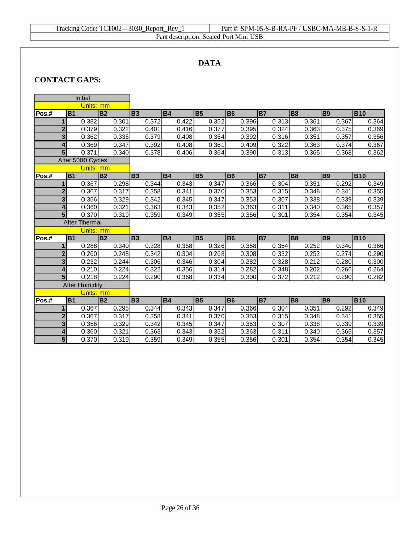
CONTACT GAPS:
Units: mm Units: mm Units: mm Units: mm
0.301 0.292 0.202 0.194
0.422 0.370 0.372 0.374
0.367 0.343 0.294 0.302
0.0284 0.0201 0.0482 0.0494
50 50 50 50
After 5000 Cycles
St. Dev.
Count
Initial
Minimum
Maximum
Average
Maximum
Average
Maximum
Average
Count
After Thermal After Humidity
Count
Minimum
Maximum
Average
St. Dev.
Count
MinimumMinimum
St. Dev.St. Dev.
Tracking Code: TC1002—3030_Report_Rev_1 Part #: SPM-05-S-B-RA-PF / USBC-MA-MB-B-S-S-1-R
Part description: Sealed Port Mini USB
Page 18 of 36
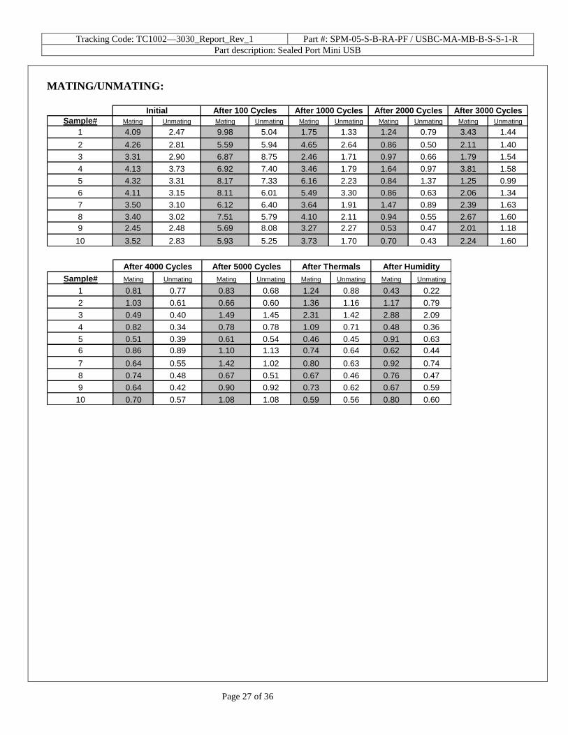
MATING/UNMATING:
Newtons Force (Lbs) Newtons Force (Lbs) Newtons Force (Lbs) Newtons Force (Lbs)


![cikguadura.wordpress - trial.spmpaper.me SPM TRIAL SBP CHEMISTRY... · SULIT 4541 KIMIA 2016 5 (d) [Able to describe briefly the verification of anion present in sulphate salt correctly]](https://static.documents.pub/doc/80x56/5e1a3fcae8c62a71446f4306/-trialspmpaperme-spm-trial-sbp-chemistry-sulit-4541-kimia-2016-5-d-able.jpg)


