IT 13 037 Examensarbete 30 hp Juni 2013 Design verification through software architecture recovery Meeting ISO 26262 requirements on software using static analysis Oscar Molin Institutionen för informationsteknologi Department of Information Technology
Transcript
IT 13 037
Examensarbete 30 hpJuni 2013
Design verification through software architecture recovery Meeting ISO 26262 requirements on software
using static analysis
Oscar Molin
Institutionen för informationsteknologiDepartment of Information Technology
Design verification through software architecturerecovery
Oscar Molin
Emerging functional safety standards in the automotive industry will create newchallenges for companies sitting on large deposits of legacy code. When refactoringexisting code for compliance with standards such as ISO 26262, great savings could bemade if work products required by the standard could be automatically generatedfrom existing source code.
In this thesis, we explore the possibilities to generate graphical softwarearchitectures, data-flow graphs and software architectural descriptions directly fromexisting C source code. By parsing the source code to find structures and therelations between them, we were able to create relational graphs that represents thesoftware of an entire system or that of just one component, using different levels ofabstraction where appropriate.
We create a proof-of-concept toolchain that can generate two kinds of graphicalarchitecture views and one data-flow view. Although these tools are by no meansready for production, they do show promise and are already useful as developmenttools for better software understanding.
Finally we test the toolchain on current production ECU (Electric Control Unit)software used in heavy trucks and buses and evaluate the results against therequirements of the ISO 26262 standard. This thesis was done at Scania CV AB inSödertälje, Sweden.
Tryckt av: Reprocentralen ITCIT 13 037Examinator: Philipp RuemmerÄmnesgranskare: Roland BolHandledare: Mattias Nyberg
1.1 Motivation and goals.................................................................................................................31.2 Previous work............................................................................................................................31.3 Thesis scope and limitations......................................................................................................41.4 Organization of this thesis.........................................................................................................4
2 Background........................................................................................................................................52.1 Functional safety........................................................................................................................52.2 (Automotive) Safety Integrity Level..........................................................................................52.3 ISO 26262:6 ”Product development at the software level”.......................................................62.4 The C programming language...................................................................................................6
2.4.1 Function calls and parameter passing................................................................................72.4.2 Pointers...............................................................................................................................7
2.6 Case: Scania embedded software...............................................................................................82.6.1 ECU OS Description..........................................................................................................82.6.2 ECU applications and software structure.........................................................................112.6.3 Scania and ISO 26262 standardization.............................................................................11
2.7 Relevant ISO 26262 requirements and provisions...................................................................112.8 Graphical representation..........................................................................................................132.9 Defining thesis goals................................................................................................................142.10 Software Architecture Recovery............................................................................................14
2.10.1 Existing software support...............................................................................................142.10.2 ISO 26262 certified tools...............................................................................................15
2.10.3 Dependency graphs from text search and pattern matching...............................................162.10.4 Static analysis using the Abstract Syntax Tree...................................................................16
3.1 Source code parsing with meta data........................................................................................193.1.1 Pre-processing source code..............................................................................................193.1.2 Parsing source code..........................................................................................................19
3.2 Defining a software architecture..............................................................................................203.2.1 Program dependence graph..............................................................................................203.2.2 Call graph tree..................................................................................................................213.2.3 Control flow – control dependence..................................................................................213.2.4 Data-dependence – data-flow...........................................................................................23
3.2.4.1 Hidden dependencies and data-flow.........................................................................233.2.5 Defining data dependence and data flow.........................................................................233.2.6 Function calls...................................................................................................................24
3.3 Creating an architectural description.......................................................................................253.3.1 XPath queries and grammar.............................................................................................263.3.2 Description XML format specification (using XML 1.0)................................................273.3.3 Description XML example...............................................................................................28
3.4 Creating graphs........................................................................................................................303.4.1 Edge and node styles, legend...........................................................................................313.5 Graphviz graph layout and dot graph description language................................................32
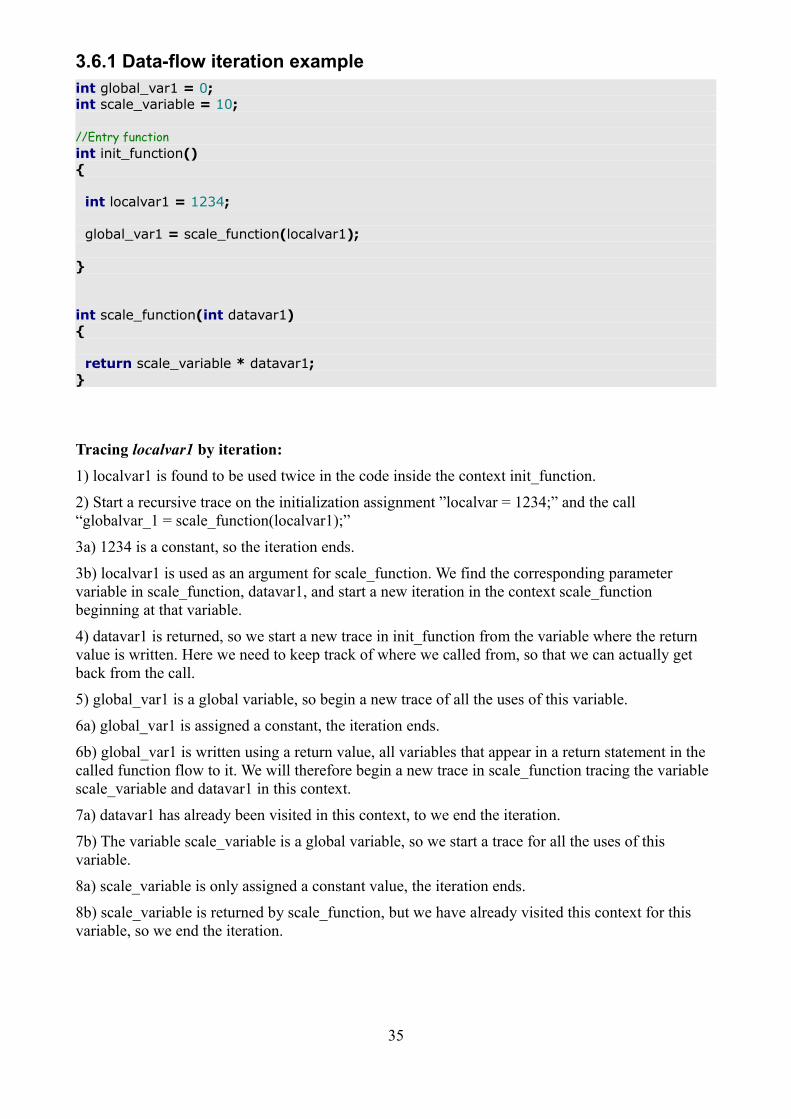
3.6 Data flow graphs......................................................................................................................323.6.1 Data-flow iteration example.............................................................................................35
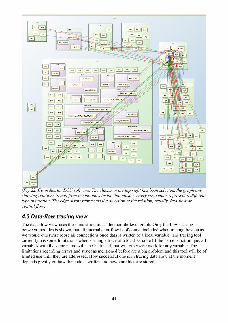
4 Evaluation of results........................................................................................................................394.1 Variable-level abstraction view................................................................................................394.2 Module-level abstraction view.................................................................................................404.3 Data-flow tracing view............................................................................................................414.4 ISO 26262 requirements evaluation........................................................................................424.5 Future improvements and feasibility.......................................................................................434.6 Conclusion...............................................................................................................................44
5 Licensing and acknowledgments.....................................................................................................456 Vocabulary.......................................................................................................................................47References..........................................................................................................................................50
2
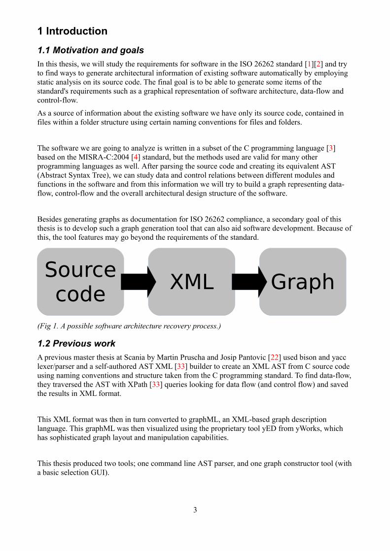
Sourcecode XML Graph
1 Introduction
1.1 Motivation and goals
In this thesis, we will study the requirements for software in the ISO 26262 standard [1][2] and try to find ways to generate architectural information of existing software automatically by employing static analysis on its source code. The final goal is to be able to generate some items of the standard's requirements such as a graphical representation of software architecture, data-flow and control-flow.
As a source of information about the existing software we have only its source code, contained in files within a folder structure using certain naming conventions for files and folders.
The software we are going to analyze is written in a subset of the C programming language [3] based on the MISRA-C:2004 [4] standard, but the methods used are valid for many other programming languages as well. After parsing the source code and creating its equivalent AST (Abstract Syntax Tree), we can study data and control relations between different modules and functions in the software and from this information we will try to build a graph representing data-flow, control-flow and the overall architectural design structure of the software.
Besides generating graphs as documentation for ISO 26262 compliance, a secondary goal of this thesis is to develop such a graph generation tool that can also aid software development. Because ofthis, the tool features may go beyond the requirements of the standard.
(Fig 1. A possible software architecture recovery process.)
1.2 Previous work
A previous master thesis at Scania by Martin Pruscha and Josip Pantovic [22] used bison and yacc lexer/parser and a self-authored AST XML [33] builder to create an XML AST from C source code using naming conventions and structure taken from the C programming standard. To find data-flow,they traversed the AST with XPath [33] queries looking for data flow (and control flow) and saved the results in XML format.
This XML format was then in turn converted to graphML, an XML-based graph description language. This graphML was then visualized using the proprietary tool yED from yWorks, which has sophisticated graph layout and manipulation capabilities.
This thesis produced two tools; one command line AST parser, and one graph constructor tool (witha basic selection GUI).
3
1.3 Thesis scope and limitations
In order to keep the amount of work manageable, some limitations have been set for this thesis:
• As the input data for our proposed process, only C90 source code will be considered along with its folder structure (if any), no other programming languages or dialects.
• Only relationships that exist in source code are considered when recovering software architecture, not relationships defined in documentation, naming conventions or other metadata.
• All input source code is considered as one project. External identifiers must be unique.
• Some C language features are represented in a simplified way, ex. arrays/structs are considered as single variables.
• Assembler code, precompiled libraries etc are not considered, all input source code must be C-code only.
• External variables are considered independent of C modules, but external functions are not.
• Only the parts of the ISO 26262-6 standard that are explicitly mentioned are considered in this thesis. For example, mapping requirements to the architecture is not done, and only a single system/ECU is considered at one time.
• External hardware and hardware/software interactions are not considered.
• Task scheduling and other dynamic aspects are not considered.
• Software tool requirements and confidence levels defined in ISO 26262 are not considered for the proof-of-concept tool.
1.4 Organization of this thesis
In this thesis we first investigate the subject of software architecture recovery and the software we will be applying it to. We want to find a method that will suit the requirements of the ISO 26262 standard.
Then we will define software architecture and data-flow using definitions based in programming language constructs. This will result in a software representation that can hold all the information we need to satisfy those ISO 26262 requirements we are considering.
Lastly we create an implementation of a tool that can recover architectural information from source code and create graphical views to display that information. The views are then evaluated to see if some requirements of the ISO 26262 standard can be met using this method and discuss what can be improved on and what limitations this method might have.
4
2 BackgroundEmerging standards for functional safety for software in embedded systems like the ISO 26262 standard for functional safety in road vehicles and for more general applications, the IEC 61508 [5](and its derivatives) standard for functional safety in electronic safety-related systems will put manyrequirements on the development of software in embedded systems. This thesis will mostly address requirements in ISO 26262-6 for software in road vehicles.
Embedded systems exist today in great numbers in cars, trucks and buses. Microcontrollers, used in ECUs in vehicles (Electric Control Unit), are taking control of more and more features in vehicles and other heavy machinery today.
Even critical things like brake systems that in the past were controlled by purely mechanical/hydraulic means are now left, at least partially, in the hands of ECUs and their software.This is now a reality in cars, spacecraft, locomotives and fighter jets alike. As this software is relied on for increasingly critical and complex systems, there is growing demand from industry, consumers and legislators to standardize the development of embedded software to ensure that is is safe and of high quality. The more safety critical the system is, the higher the demand will be that it does not fail causing property damage, personal injury or death.
2.1 Functional safety
The ISO 26262 standard is based on the concept of functional safety. This concept involves identifying hazards for a given function, creating requirements to prevent these hazards and allocatethese requirements to the architecture of the system.
In the standard's vocabulary, it is described in this way:
“functional safety concept specification of the functional safety requirements ..., with associated information, their allocation ... to architectural elements …, and their interaction necessary to achieve the safety goals” (ISO 26262-1 Vocabulary)
The details of this is outside the scope of this thesis but some parts will be explained below.
2.2 (Automotive) Safety Integrity Level
ASIL is an important part in the ISO 26262 standard and is the way hazards are graded on a scale. All elements/items in a system design will be assigned an ASIL level designating how safety-critical it is. The levels are A, B, C, D where A is least critical and D is an item whose failure may lead to death. Which level an item has depends on the probability of failure, the ASIL level of itemsit relies on and the consequences of the failure. Non-critical elements are given the level Q/M.
After identifying hazards, an item is given an ASIL level based on these hazards. An item with a certain ASIL level must meet a required maximum probability of failure. The standard requires that these ASIL levels are inherited, meaning that every subsystem of an item inherits the highest ASIL level of any of its ancestors.
5
This concept also applies to software where the same kind of inheritance happens as the software in a system of many ECUs is decomposed first down to individual ECU software, then software components, modules and so on. This already imposes some implied restrictions for how the software is structured since software with many dependencies will have harder ASIL requirements, and will push development towards components that are mostly independent of each other. As we will see when we get further into the standard, development for the highest integrity level, ASIL D, can be difficult and expensive. Explicit recommendations are given in the ISO standard which can be used as a guide to achieve a certain ASIL grade in a software item.
2.3 ISO 26262:6 ”Product development at the software level”
Part 6 of the standard on the topic of software development has 11 clauses and 4 annexes. This thesis will address only the ones concerning actual software development, programming standards, programming guidelines, software design and software verification. These topics are found in clause 5-11 in part 6 of the standard.
Each clause contains a number of requirements and each requirement is graded for all the ASIL levels and may give a different grade depending on which ASIL level an item is developed for.
++ highly recommended
+ recommended
o no recommendation for or against
Many (o) suggestions are unnecessary or redundant. This can bee seen in the fact that some requirements are marked (++) for ASIL A and only (o) for ASIL D, which usually means that the issue the recommendation addresses is solved by other means. This may be requirements such as formal verification for example, which if used is generally thought to allow developers to skip testing altogether because the correctness has already been proven.
To give a general idea of the standard's requirements for software, if a requirement has positive effects and is not covered by other requirements, but still only has (+) grade for the highest integritylevel ASIL D, it is usually very hard and/or expensive to fulfill. In the same way, methods with positive effects already universally adopted in the software industry and that bring little extra cost todevelopment will almost always have a (++) recommendation.
2.4 The C programming language
(The following is for the non C-speaking audience only)
In C, programs are constructed from function and variable declarations [14] on which operations areperformed. Functions in turn may contain parameter declarations, variable declarations, other function declarations and so on. Functions can also contain selection/control statements which in turn can contain function and variable declarations.
Each of these contexts where things are declared are called blocks, which is a kind of scope where declarations can is reachable. Declarations in one scope is visible in all sub-scopes/blocks of that scope, but not in any parent blocks. The top level scope is called the file scope, where global variables and functions can be declared.
6
C program source code is written in .c text files and .h files. Each file has a file-scope that is local toonly that particular file. There is also an extern file scope, which is visible to the whole program. .h files generally don't contain program code but only global information and external declarations used to make global functions and variables visible to other .c files.
A simplified view, if we ignore sub-blocks, is that there are 3 blocks where variables can reside, extern global, static global and block scope. Functions can by the same view exist in extern global och static global scope. This assumption is made throughout this thesis, because of restrictions made by the MISRA-C standard [4] and because it simplifies our work process .
2.4.1 Function calls and parameter passing
In C, function calls with parameters are made as call-by-value [15]. The function call arguments arecopied to the called functions corresponding parameter variable when the function call is executed. The call interface is the only proper entry point into a function that we allow.
2.4.2 Pointers
Pointers are variables that contain an address in memory, which the pointer points at. In C a pointer can point to any type of variable, including other pointer variables (pointers to pointers) or whateveris at a particular address in memory. Pointer-alias analysis for C-programs is particularly difficult [16].
Pointer address arithmetic and the global nature of pointers allows them to transgress any boundaries set forth by the C language such as scope. Pointers in static analysis are hard to interpret, especially if they are reused to point to different addresses. For example, if two tasks in a program assign a value to a pointer and some other task de-reference it to write to the pointed-to variable, it would be impossible to know which of the two pointer values were used to find the target variable through only static analysis (assuming we can't take task scheduling into consideration).
2.5 Programming standards
(Many topics in the section are covered in Les Hatton's book “Safer C” [18])
Programming standards are employed in all serious software development today and are used to force developers to avoid certain aspects of a programming language, or steer them towards writing their software in a certain standardized way. Programming standards, almost always combined with more stylistic programming guidelines, are used to make source code more readable, maintainable, safe, unambiguous and less complex.
C has been a big target for coding standards as it is very flexible and can allow the programmer to do almost anything that the hardware is capable of, with the exception of hardware specific instructions not part of the C language. Because the possibilities are so great, the possibility of erroris as well.
The C programming language was created in 1972 by Dennis Ritchie and was finally standardized in 1989 by ANSI and in 1990 by ISO where it is now known as ISO/IEC 9899:1990, or C90 for short [18]. Several programming standards have emerged [26][27][28] to tame the more error proneuse of the language by asserting rules and recommendations.
7
The C standard contains several ambiguous or undefined parts categorized as unspecified behavior, undefined behavior, implementation-defined behavior and locale-specific behavior [19]. Ambiguous behavior, as defined in the C standard, can be avoided through the means of a programming standard that addresses these issues.
To verify compliance to a programming standard and programming guidelines, it is important to create a standard that can be automatically enforced by the use of compliance checking and code inspection tools [20].
2.5.1 Static analysis tools
Much unwanted behavior can be detected by static code analysis, but some requires dynamic analysis where the program is checked while it is being executed.
Scania maintains a company programming standard and style guidelines for C based on the MISRA-C:1998 and 2004 standard and ISO C90 [21], and check their conformance with special tools. They employ static analysis tools PC-lint (a lint [29] derivative) from Gimpel Software and QA-C from Programming Research as well as other tools.
2.6 Case: Scania embedded software
Scania CV AB is a truck manufacturer founded in 1891 with headquarters in Södertälje, Sweden. They currently develop, maintain and produce heavy trucks, buses as well as standalone engines forindustrial use. All vehicles produced make use of several ECUs and most ECU software is developed in-house with a few exceptions where software is developed by external suppliers.
2.6.1 ECU OS Description
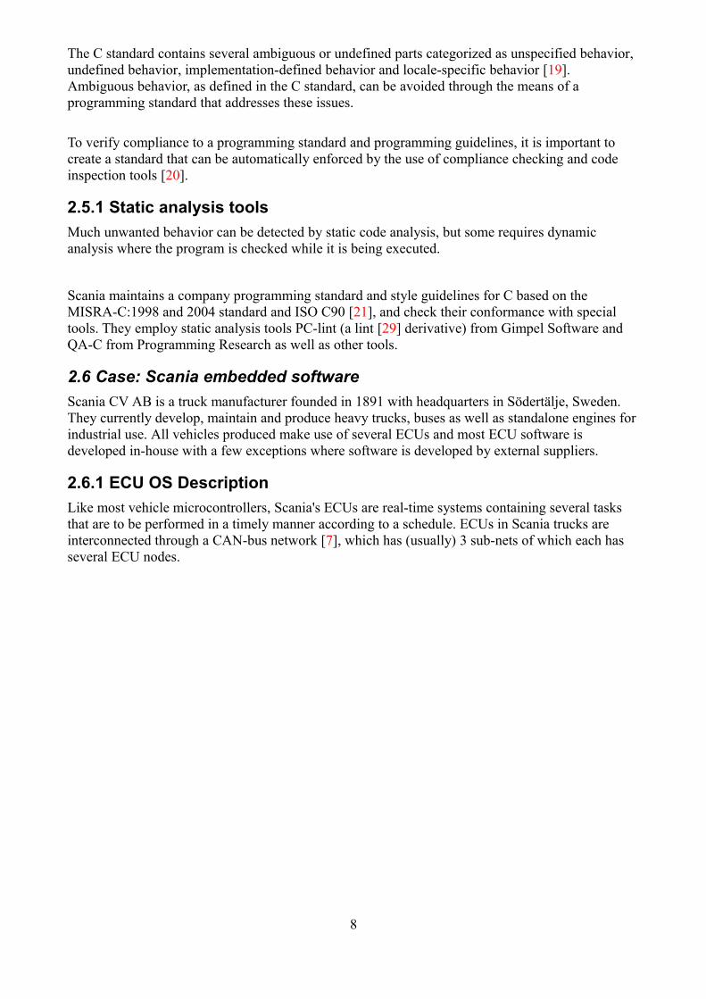
Like most vehicle microcontrollers, Scania's ECUs are real-time systems containing several tasks that are to be performed in a timely manner according to a schedule. ECUs in Scania trucks are interconnected through a CAN-bus network [7], which has (usually) 3 sub-nets of which each has several ECU nodes.
8
(Fig 2. Scania CAN bus network architecture.)
Communication between these three subnets is routed by one single ECU called the co-ordinator (COO). Local subnets and virtual subnets may also exist. The ECU's microprocessor architecture may vary. One processor that is used is the Freescale MPC series of microcontrollers.
9
(Fig 3. Cross-section showing typical ECU placement in a truck. Courtesy of Scania CV. Note the EMS (Engine Management System) ECU mounted directly on the engine block.)
The real-time operating system used in most ECU software at Scania is a self-developed primitive non-preemptive RTOS written in C called ComP (Common Platform) [6].
ComP contains hardware abstraction layers for accessing hardware features like AD/DA converters,CAN interfaces and so on. Some parts of ComP are ECU specific and the rest is common to all ECUs, such as different utility functions (unit conversions, filters etc.). At the core is a task scheduler which manages different tasks in timed loops (loops that execute at regular intervals) according to how long worst case execution time the task has. The loops can be executed with 1000Hz, 100Hz, and 20 Hz frequencies and so on, and tasks in each loop are registered when ComPstarts up. Task switches are done by a tick timer which interrupts the CPU at certain intervals (the interval depends on which timed loop that is currently executing).
This sounds like a pre-emptive scheduler, but Scania has chosen to use a simpler design where no useful task is assumed to be executing when the interrupt is raised. Because of this, ComP can get along with only one stack and no need for semaphores, mutexes etc when communicating between tasks. The downside is of course the almost inevitably low utilization factor, slow task communication and heavy use of global variables, something considered unsafe by many [4][18] but still common practice, especially in embedded systems where memory size and CPU speed are often limiting factors.
To ensure that a task actually finishes on time, an internal/external hardware watchdog is used which can reset the ECU if a task doesn't complete within its allocated time period.
10
2.6.2 ECU applications and software structure
(Some of the following is specific to Scania ECUs EEC3 and S8.)
Besides ComP each ECU has applications called managers in Scania terminology, where each manager contains one or more modules, which at Scania is one .c file and a corresponding .h file along with an optional _cal file, which has no real significance and is only used to declare a module's global variables so that they don't clutter the regular .c file with declarations.
Managers are organized in layers where some managers are allocated to a layer that each has a time-loop handler module that defines the execution order within that layer. Depending on the interpretation of ComP, managers can be considered real-time tasks of sorts, to use more common terminology.
2.6.3 Scania and ISO 26262 standardization
The vehicles produced by Scania CV AB are heavy trucks and buses only. ISO 26262 today is specifically targeted toward road vehicles with weights under 3,5 metric tonnes. As such it is not a requirement for Scania or other truck manufacturers today to follow this standard. However, regardless of this, this standard is believed to either be extended to trucks or be followed by similar standards covering them.
Scania believes that such a standard may become a legal requirement in some of the markets where they operate and this is part of the reason why this standard interests them.
2.7 Relevant ISO 26262 requirements and provisions
In this section we will go through parts of ISO 26262-6 that may be relevant to our case and that can be used to justify the need for the processes proposed by this thesis. Quotes are taken from the ISO 26262-6:2011 document.
Clause 5.4 discusses the choice of programming language (or model based development) and has some strong recommendations about programming standards and requirements on the programminglanguage used. These recommendations imply the use of a programming standard to improve code quality and to prevent use of undefined properties of programming languages.
For the language C, this is very relevant, and is addressed by several standards, the most popular being MISRA-C, which is already partially used at Scania. The ISO 26262 standard mentions MISRA-C explicitly as an example of a coding standard for C [2]
From clause 5 table 1 we get some relevant recommendations:
1a) Enforcement of low complexity
1e) Use of established design principles
1f) Use of unambiguous graphical representation
11
Next in clause 7.2 we have the following statement:
“The software architectural design represents all software components and their interactions in a hierarchical structure. Static aspects, such as interfaces and data paths between all software components, as well as dynamic aspects, such as process sequences and timing behavior are described.”
Clause 7.4.5:
“The software architectural design shall describe:
a) The static design aspects of software components... the software structure including its hierarchical levels.
b) The dynamic design aspects of the software components...
data-flow between software components... data-flow at external interfaces”
In clause 7.4 table 6 on methods for verification of the software architectural design, the important requirements for us are the following:
1b) Inspection of design
1f) Control-flow analysis
1g) Data-flow analysis
This is the most important part of the standard for this thesis. The architectural design itself is also used as a tool in other development tasks that need to be done according to the standard. By using the architecture as a point of reference, we can allocate or map things such as requirements or safetygoals to the architecture and then later refer to it in documentation, for example to prove that a software component is independent of another component.
Having such an architecture will help the development, as mentioned at the beginning of clause 7.2:
”The software architectural design provides the means to implement the software safety requirements and to manage the complexity of the software development.”
Clause 8 table 8 makes some restrictions on programming language features which are mostly covered by standards such as MISRA-C, and this is also mentioned in the standard.
Clause 8.4 table 9 makes almost the same recommendation as 7.4 table 6 above, about the methods of verification of software unit design and implementation.
To summarize, these are some of the things we need for software development:
• An architectural design that can be verified (using various means mentioned already)
• If the design uses a graphical representation, it should be unambiguous
• A design of software units and a software implementation that can be verified
• We should use established design principles to do the above mentioned tasks
• We should do data-flow and control-flow analysis on our software
12
2.8 Graphical representation
The representation of software as graphs is a natural extension of traditional graph drawing of maps,relational graphs, game boards, nautical charts etc. The techniques used in software graphs today were conceived over a millennia ago and hasn't changed much with the exception of 3D graphs. Theusefulness of the latter for software representation is debatable.
In software engineering, creating some form of graphical representation of software design has beendone as long as software has existed. Representations used usually depends of the level of abstraction that is to be shown. Architectural description languages exist to formalize software architectures, but there is no single standard and the graphical representation of such a description varies greatly.
(Fig 4, 5. To the left, a typical UML diagram used in Scania documentation. To the right, the tree of virtue as a tree graph, made in the middle ages.)
UML diagrams are popular in high level representation, and is used in some of Scania's architectural documentation as well.
Directed graphs are used in some graph languages such as DOT, GXL, GraphML which is commonly used in software engineering and education to display software in various ways. An advantage of directed graphs over undirected is that they can describe hierarchies by enforcing ranks on graph nodes based on the direction on the edges.
Model based development usually has graphical models that are used to generate source code, which we won't go into here since the ISO 26262 standard allows for model based development andsince the model generally means that a good enough design description already exists, it's not relevant here.
13
Logic diagrams and state machines are used to describe behavior, but this doesn't really describe thearchitecture of software very well. It can however be useful when describing low level control and data-flow.
In real-time systems, timing graphs are usually used in addition to the graph types mentioned above.
2.9 Defining thesis goals
As was already discussed, Scania is working towards supporting ISO 26262. Part of this work has been identified as creating a software architectural design and being able to analyze and verify this design against the actual implementation. Because Scania has a large amount of software not developed with the standard in mind which lacks a lot of design documentation which would be required, generating some of this documentation from the existing source code has been proposed.
The goal of this thesis is to study different methods for doing this and to create a proof of concept tool that can generate software architectural views that include data-flow, data dependency and other forms of dependency information that can be recovered from the source code using static analysis. This tool should preferably also be of help to developers in aiding them to create software closer to the recommendations of the ISO 26262 standard such as software with limited complexity,modular software and software with highly cohesive components and low coupling between with components.
2.10 Software Architecture Recovery
Creating a software architecture from existing software is referred to as Software Architecture Recovery. One method generally used for software architecture recovery is analyzing source code by static [8] and/or dynamic analysis, looking at any documentation available, code comments, folder structures, metadata etc to recreate a meaningful architecture of the software.
Possible motivations for doing this might be:• The existing architecture [11] no longer matches what is actually implemented due to code
maintenance/development.• Verifying if a change made to some software component alters the software architecture.• No documentation about the architecture exists, or it lacks in detail.• The existing architecture description is incorrect for some other reason.
The usage scenario may involve legacy software that needs to be updated or refactored in some waythat requires the creating of a software architecture description. Of course it is possible to apply this method to new development as well, although most people will likely benefit more from an architecture description as a tool to write better structured code, therefore creating an architecture afterward may seem a little backwards. It would still be useful for generating reference information and documentation for future maintenance use etc.
A key advantage compared to a manually created architecture is that the information automatically generated from code will always be current and correct, at least to the degree that the generation-tool allows (assuming it's correct itself).
2.10.1 Existing software support
There would at first glance appear to be an abundance of software tools targeting software architecture recovery. However, while we have so far uncovered references to probably upwards of
14
40 [11] tools, these are almost exclusively research projects that push out a tool, write a few articles and then stop all development and availability of the tool, and in most cases we doubt that the tool was ever made publicly available at all.
Simpler kinds of tools are available in some compiler suites or IDEs such as Visual Studio, Eclipse [12] but are usually limited to a simple call graph, a control-flow graph, class diagrams (not applicable in C) and can not be considered to meet any ISO 26262 requirements with the output they produce.
A few larger commercial tools do exist that may be of interest:
Understand, Scientific Toolworks Inc (non-free, trial)This tools does provide an architectural view, however we found the output on our test case to be hard to interpret and having very little detail. The view provided was on a file basis, showing dependencies between every .c and .h file in a project. The tool also provides call graphs and control-flow graphs.
Klocwork Inspect/Insight, Klocwork Inc (non-free, unavailable trial)Although some videos provided of this tool on the Klocwork website showed promise, Klocwork did not respond to our repeated requests for a trial version meaning that we were unable to test on any real code. The tool provides call graphs and control-flow graphs and an architectural view (or dependency graph).
LDRA Tool suite, LDRA Ltd (non-free)The tool provides call graphs and control-flow graphs and claims to provide explicit support for ISO 26262. They claim to provide an architectural view of software, but this is not shown on their website and they have not responded to our requests for an example image of one of these views. They also provide no trial version of their software.
Grammatech CodeSonar (non-free, supposedly an evaluation version available)
Appears to provide call-trees with graph manipulation features, mostly static analysis with warnings/suggestions and also control-flow graphs. Responded at first but would not provide us with an evaluation version.
Programming Research Structure101 for QAC (non-free, evaluation by request)
Software architecture recovery tool that is an extension for QAC, a well-known static analysis tool.
Programming Research provided us with an evaluation version as Scania happens to be a customer of theirs already. After a few weeks being in contact with their support department to actually make the program run and failing at every step of the way, we decided not to pursue this further due to time constraints. This tool requires a license for QAC static analysis tool and operates on project reports generated by QAC. This part requires a lot of tailoring to work with an existing project's source-tree.
The tool Understand is shown in the thesis of Martin Pruscha and Josip Pantovic at Scania [22].
2.10.2 ISO 26262 certified tools
Part 8 of the ISO 26262 standard contains criteria for the use of software tools in development of software and other work products. Requirements similar to those applied to software are applied to software tools used in the development, testing etc of software. A certain confidence level is required for a given software tool when developing software/hardware.
15
As with other development according to the standard, ASIL level classification is done for software tools also using a set of requirements that apply only to software tools. The ASIL level required for a tool is the same as the highest ASIL level of the target it is applied to.
Interestingly, ASIL D for software tools requires that it is developed according to a safety standard such as ISO 26262 or similar, which means that eventually, a tool must be developed without such arequirement fulfilled for the tools used to develop the software tool (and so on).
Some commercial tools already advertise some form of ISO 26262 compliance, and this can be expected to become more common as more developers adopt the standard in the automotive industry. Our own implementation will not consider this aspect, as besides time constraints, letting developers certify their own product for safety is generally not a good idea.
2.10.3 Dependency graphs from text search and pattern matching
A primitive or maybe optimistic way to create a high level architecture is to use regular expressions to find some matching patterns in the source code, and use these to link two components (defined assource code files, or by language-specific code blocks) together. As long as our code fits the regularexpression perfectly, we get an architectural description limited by the structure we can handle in our search expressions. The more detail we want from this method, the more details of the programming language have to be added.
A method to structure the gathered information is called clustering [23], where components with many relations to each other are clustered together, forming groups. Representing this in a graph, we can give weights to the edges of the graph according to if two components or nodes are closely related, making these edges shorter and paths less traveled get longer edges. Such a view can give some idea of the software structure, but we get no hierarchical information without creating very complex search expressions or relying strict easy-to-parse calling conventions between software components. An example of the latter could be the notion of software component “ports”, which is widely used in literature and in other software standards such as AUTOSAR [24].
To get a sense of which component depends on which, we need to add directions to our relations and to do that we need to define what constitutes a certain relation. This will inevitably require correctly understanding the whole of the programming language that is used and regular expressions and similar methods will eventually get too difficult to use. Fortunately there are methods much better suited for more detailed parsing of source code.
2.10.4 Static analysis using the Abstract Syntax Tree
To be able to parse source code correctly, we will turn to the Abstract Syntax Tree (AST) representation since it gives us the source code described in a more well defined way that will be easier for us to look through to find what we want such as a certain kind of relation, a unit of a program and the program structure as described by the programming language (functions, methods, blocks). The AST is the preferred way in most situations where code analysis is to be performed and is also used internally by compilers, for code optimization etc.
Similar combinations of parsing source code into AST, creating some description in an architecturaldescription language of some sort and then displaying it in a clustered graph is a tried method [23]
16
[25] and is one of the few methods that can be applied without any knowledge of the software except which language it is written in.
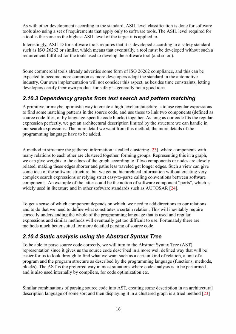
If additional artifacts exist, they could of course be incorporated into an architectural description, for example if there is a naming convention for source files or folders that gives hints of the architecture. An additional reason for this is that a structure created only from source code will lookexactly like the source code, so if the source code is complicated and hard to structure by hand it will look just as complex and hard to understand when structured. However, in that case, these sources could be incorrect, while the source code itself will always represent the true state of the architecture if it is interpreted correctly.
(Fig 6. A manually created low-level software architecture, created from mixed sources. This image was created at Scania for evaluation purposes, and the process proved to be very time consuming.)
Manual methods (Fig 6) won't be discussed here and it is an assumption made in this thesis that manually creating a software architecture from nothing but source code is too costly, time consuming and error prone which is one of the motivations behind this thesis.
2.10.5 AST Parsers
A C-parser called “standard” which creates abstract syntax trees in XML format, was created by Martin Pruscha at Scania for a previous master thesis. It proved to be difficult to use because it usedXML in an inefficient way, adding nodes as children instead of siblings. This caused deeply nested nested XML that could not be queried efficiently using XPath or by other means.
There are few similar tools available such as the commercial “DMS Software re-engineering toolkit” as well as open source alternatives of varying quality. One among them is srcML [30] which we finally decided to use. It is a parser for C, C++ and Java that produces a selected AST in XML-format.
17
NOxupstream
sensor part
VNUMRecieve engine Nox model value
NOx flöde -> ppm samtväljer NOx värde innan katalysatorn från
sensor eller från modellerat värde
V1: Use NOx sensor value, (L1)V2: Use modeled value from EMS (E2, E3)
COMP (SW)HW: ADC, CAN controllers,
PWM, I/O
LLAP
VSENVirtuella sensorer
Sensoreroch
Aktuatorerwires
APPLApplikationsnivå
L1 (NOx sens driver) Deliver ppm measured by NOx sensor
E2 CAN J1939 signal Convert CAN signal to
g/min
E3 CAN J1939 signal Convert CAN signal to
kg/min
E5 CAN J1939 signal Convert
CAN to -
L2 (Analog temp sens
driver) Conv V to degC
B1 ADC
llap_t_scrInlet_S16 degC
E6 CAN J1939 signal CAN to
hPa
E7 CAN J1939 signal CAN to
hPa
llap_dm_UreaReqEms_S16 g/minRequested dosing of Urea (EMS)
L3 (Analog temp sens
driver) Conv V to degC
B2 ADC
L4 (Analog temp sens
driver) Conv V to degC
B3 ADC
W12
S3 SCR inlet exhaust temp
sensordual pull up,
(choose resist. in SW)
llap_r_NOxUpStream_S16 ppm
llap_dm_NOxModelUpStream_S16g/min (från modell i EMS)
llap_dm_exhaustFlow_S16kg/min (från EMS)
DOSCDosing control
Styr SCR injektor, (Urea dosing unit)Beräknar ontid för Ureainsprutning från begärd dos och tryckförhållanden
1 Test: High pressure check for UreaActual
L5 (Analog pressure sens
driver) V to hPa
B4 ADC
W13
L6 Urea injector driver and diagnosis
B5 ADCB7
PWM in
SCR Pump
B8PWM out
PUMCPump control
Styr ureapumpen för att hålla konstant tryck vid doseringsenheten
Only in Engines path, not in Eu6, EU6Inc. They use a tripple high temp sensor
(CAN)
S-B8: Generate electrical PWM-signal at output port
S-PUMC: Make pump pressure constant.
S-S7b: Make pump motor rotate with speed
smhy_r_pumpPwm_S16 %.
S-S12: Create rotation based on W19, and W20.
L7a Pump speed sensor driver
L7b Pump motor driver and
diagnostics
L7a:T5:feedback signal SCGT6:feedback signal OL or SCB
S-S7a: Deliver pump rpm.
S-B7: Deliver frequency at input port.
S-L5: Deliver pump pressure.
S-B4: Deliver voltage at input port.
Con
tro
l sig
nal S
CB
Con
tro
l sig
nal S
CG
Fee
dba
ck s
igna
l SC
GF
ee
dbac
k si
gn
al O
L o
r S
CB
Pump motor speed feedback
Su
pply
OL
Su
pply
SC
G
W10 elec. fault ?W2 OL
Signal source
W1,W3 SCG
supp
ly c
ontr
ol
B9Supply
S-B9: Deliver supply to output port based on
supply control.
L5:T1: SCG W13T2: SCB or OW W13V1: use sensor valueV2: use replacement value
L4:T1: SCG W12T2: SCB or OW W12V1: sensor valueV2: replacem. val.
Controller
NOx sensor upstream
EMS to EEC3 CAN
SCR exhaust temperature
sensor
Injector sensors
Urea injector
Pump actuator
Vsen
Urea tank temperature
sensor
CAN controller + transmitter
”CAN2" specific
sensor bus
EX CAN J1939 signal
Convert signal to
CAN signal
DX CAN J1939Message
”NOx Sensor Values Up Stream ”
EMS system
S6 EMS CAN routing
CAN cable
EX CAN J1939 signal
Convert signal to
CAN signal
EX CAN J1939 signal
Convert signal to
CAN signal
smhy_dm_adblueDosingMaxLim_S16
EX CAN J1939 signal
Convert signal to
CAN signal
smhy_dm_adblueDosingActual_S16
DX CAN J1939Message
”SCR Controller Status ”
EEC3 to EMS CAN
DX CAN J1939Message ”Emission
Control Temperature”
Urea injection control
V4 Virtual sensor for the actual urea injection
Till EMS och till PUMC. Ev. också för diagnos.
DOSC tar injectionPeriod från EMS och beräknar en injection period som kan
styras ut från EEC3. Samma för
injectionDuration.
srcMLparser
Createarchitecturaldescription
mcpppreprocessor
Constructgraph
Graphvizgraph layout
dot/fdp
Graphviewer
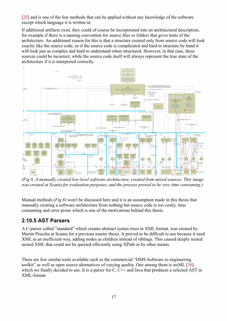
srcML has an added advantage to most alternatives in that it stores the source code inside the AST as text, which can be useful to get text from the source that doesn't match the parsers own grammar (pre-processing directives etc.). srcML was developed by Michael L. Collard and Jonathan I. Maletic, is open source and licensed under GPL.
(Fig 7. Flow-chart of our implementation toolchain. Our own implementations in red.)
18
C90Source
code
Pre-processedC-code
srcMLXML
IntermediateXML
Graphvizlanguage
SVGimage
preprocessor.rb
ast_reader.rb
module_graph.rbgraph_builder.rb data_flow.rb
viewer.html
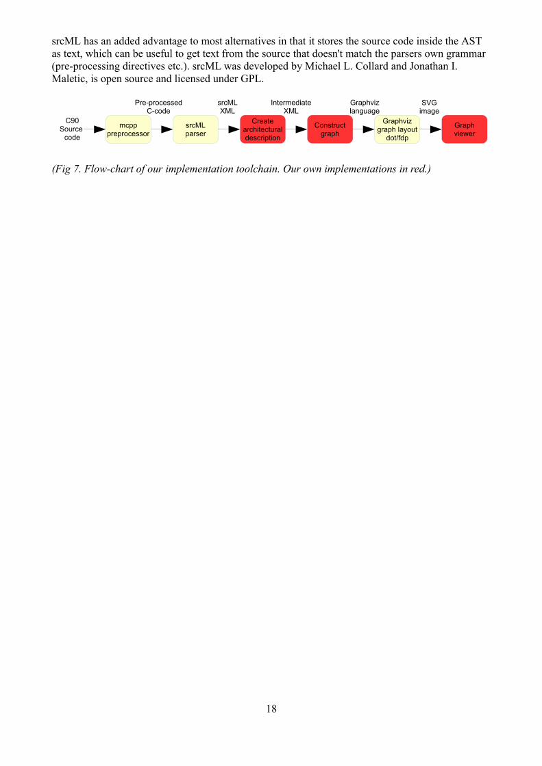
3 Tool implementationThe tool implementation is done in the script language Ruby [36] and uses XML-files as an intermediate storage format. It is constructed as a 3-stage toolchain and uses both newly written code and existing software components. All software used in the toolchain (except those written by us) is licensed with some form of open source license.
C allows the inclusion of external header-files to import functionality of one module into another, and also allows the use of macros and definitions that can make programs easier to write and make them more readable. Because these different directives are not part of the C grammar, they must be stripped away when compiling the source code. This is called pre-processing.
For this task, compilers use a pre-processing stage that translates these directives to pure C source code. Macros are translated to code, included files are copied in full into the module that included it etc. As we will not be compiling the source code, we will use a compiler-independent standalone pre-processor called MCPP. To function correctly, the pre-processor needs to find all included header-files referred to by in all the source code modules. Build systems such as make, Cmake (used by Scania) etc usually have their own implementation of how to define where these included files are located.
To simplify and to make the tool more general, we decided to include all sub-directories of the inputsource-tree along with the directory of the C standard library (any library implementation that follows the C standard can be used.) which allows pre-processing of the entire software project without any user input at all. A downside is that files with identical names will cause conflict, however this is usually disallowed in programming guidelines and was not an issue for the source code we used for testing.
3.1.2 Parsing source code
As input data we have a folder tree with source files for the whole software we want to analyze. Thefolder structure we consider as metadata, which will be used to cluster our software components.
After pre-processing, we parse each pre-processed file using the srcML parser tool called src2srcml,and save the result of each module along with the module's file path in a file. The output will be in srcML XML-format.
19
3.2 Defining a software architecture
Before we go through the next stage of the toolchain, we will define some rules that will be used when extracting information from the srcML AST and creating a software description format. We will also go though some possible interpretations which can be used to translate a software relation into a relational graph.
When employing static code analysis, a software structure can be derived by creating control flow graphs (CFG) [10], data-dependence graphs (DDG) or program dependence graphs (PDG) to visualize hierarchical dependencies in software [10]. The definition of these terms may vary slightlydepending on in what context they are used. To begin with, lets assume that the program we are to analyze is a structured program, that there is no wild use of GOTO, program statements are placed inside functions or procedures in a sensible manner and so on.
3.2.1 Program dependence graph
(Fig 9. A system dependence graph (SDG) [35], an extension of the PDG. The PDG shows the flow of the source code, and the SDG adds the dependencies of a program statement to another.)
PDGs [9][10] could be seen as a hybrid of control-flow and data-flow, basically creating a graph of every program statement and it's descendants. As with the CFG, it is on a very low level and is of little use for the abstract purposes defined in ISO 26262.
20
3.2.2 Call graph tree
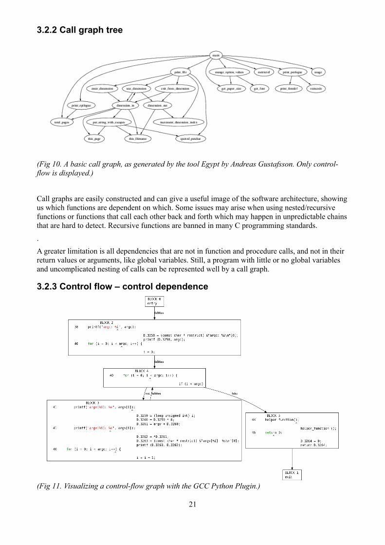
(Fig 10. A basic call graph, as generated by the tool Egypt by Andreas Gustafsson. Only control-flow is displayed.)
Call graphs are easily constructed and can give a useful image of the software architecture, showingus which functions are dependent on which. Some issues may arise when using nested/recursive functions or functions that call each other back and forth which may happen in unpredictable chainsthat are hard to detect. Recursive functions are banned in many C programming standards.
.
A greater limitation is all dependencies that are not in function and procedure calls, and not in their return values or arguments, like global variables. Still, a program with little or no global variables and uncomplicated nesting of calls can be represented well by a call graph.
3.2.3 Control flow – control dependence
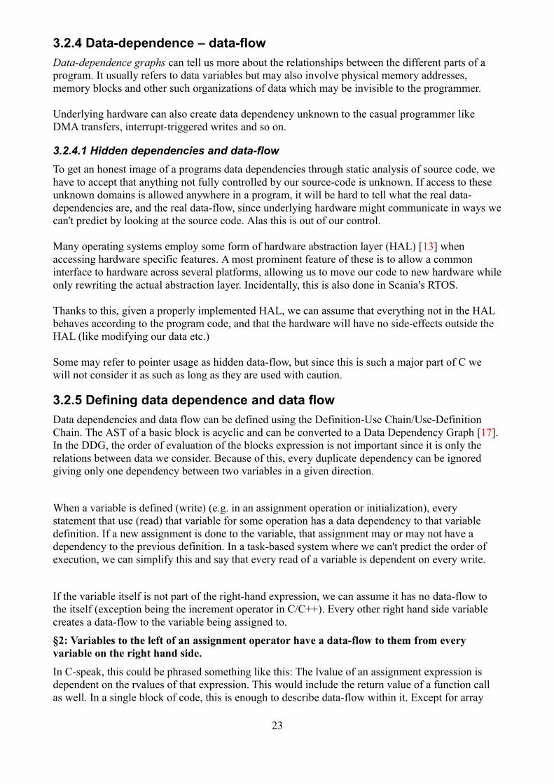
(Fig 11. Visualizing a control-flow graph with the GCC Python Plugin.)
21
Control flow would generally refer to flow determined by IF or SWITCH statements, conditional loops, basically any flow determined by the result of a conditional expression. Function calls are also a kind of control flow, which will be covered later. Control dependence is, for example, statements that depend on control-flow, like the statements inside an IF block is dependent on the conditional expressions of that IF statement. Such flow is hard to determine through static code analysis since to know which path in the control-flow graph is chosen, we have to evaluate the expressions that are part of the conditional statement involved. In general, we can only know which paths might be taken, and what every path is dependent on.
If we ignore literals, a conditional expression is just a collection of variables which are evaluated using some Boolean operators (unless it's a more complex expression like a function call). To know what variables a path in a control flow depends on, we just need to collect the variables in the conditional expression. If these variables are global, they constitute a global control dependency that can exist between different software components (modules).
We can now define conditional dependency this way:§1: If a variable is used in a conditional expression, the blocks dependent on this conditional expression has a conditional dependency on this variable.
For the conditional structures in C, conditional dependency is defined as follows:
If statements:• if block depends on the condition in the if statement.• else if block depends on the if condition, any preceding else if conditions and the current
else if condition.• else block statements depend on all preceding if/else conditions.
For loop:• initializers have no dependencies• block statements depend on the condition• increment expression also depends on the condition (can be regarded as part of the block).
While loop:• block statements depend on the condition
Do-while loop:• One iteration of the block does not depend on the condition, but all others do. To simplify,
we can consider it as a while loop with a copy of the block code standing before it.
Ternary statement:• The statement where the expression is used depends on the condition.
Switch statement:This can be a little tricky since C allows making switch (selection statements) that execute all its cases regardless of the evaluation of the condition. Switch statements without breaks after a case is banned by MISRA however, so we will assume that this is followed. In that case, every case is simply dependent on the condition.
22
3.2.4 Data-dependence – data-flow
Data-dependence graphs can tell us more about the relationships between the different parts of a program. It usually refers to data variables but may also involve physical memory addresses, memory blocks and other such organizations of data which may be invisible to the programmer.
Underlying hardware can also create data dependency unknown to the casual programmer like DMA transfers, interrupt-triggered writes and so on.
3.2.4.1 Hidden dependencies and data-flow
To get an honest image of a programs data dependencies through static analysis of source code, we have to accept that anything not fully controlled by our source-code is unknown. If access to these unknown domains is allowed anywhere in a program, it will be hard to tell what the real data-dependencies are, and the real data-flow, since underlying hardware might communicate in ways wecan't predict by looking at the source code. Alas this is out of our control.
Many operating systems employ some form of hardware abstraction layer (HAL) [13] when accessing hardware specific features. A most prominent feature of these is to allow a common interface to hardware across several platforms, allowing us to move our code to new hardware whileonly rewriting the actual abstraction layer. Incidentally, this is also done in Scania's RTOS.
Thanks to this, given a properly implemented HAL, we can assume that everything not in the HAL behaves according to the program code, and that the hardware will have no side-effects outside the HAL (like modifying our data etc.)
Some may refer to pointer usage as hidden data-flow, but since this is such a major part of C we will not consider it as such as long as they are used with caution.
3.2.5 Defining data dependence and data flow
Data dependencies and data flow can be defined using the Definition-Use Chain/Use-Definition Chain. The AST of a basic block is acyclic and can be converted to a Data Dependency Graph [17]. In the DDG, the order of evaluation of the blocks expression is not important since it is only the relations between data we consider. Because of this, every duplicate dependency can be ignored giving only one dependency between two variables in a given direction.
When a variable is defined (write) (e.g. in an assignment operation or initialization), every statement that use (read) that variable for some operation has a data dependency to that variable definition. If a new assignment is done to the variable, that assignment may or may not have a dependency to the previous definition. In a task-based system where we can't predict the order of execution, we can simplify this and say that every read of a variable is dependent on every write.
If the variable itself is not part of the right-hand expression, we can assume it has no data-flow to the itself (exception being the increment operator in C/C++). Every other right hand side variable creates a data-flow to the variable being assigned to.
§2: Variables to the left of an assignment operator have a data-flow to them from every variable on the right hand side.
In C-speak, this could be phrased something like this: The lvalue of an assignment expression is dependent on the rvalues of that expression. This would include the return value of a function call as well. In a single block of code, this is enough to describe data-flow within it. Except for array
23
indices (always data dependency), this is strictly data-flow.
In C as in most other languages, we have the notion of scope, to describe where variables reside. There is a file scope, where so-called global variables are declared. The file can be a .c or .h file. These variables can be visible to other .c and .h files (from hereon referred to as modules, per SCANIA terminology) or only visible to the file where it is declared. A global variable is visible to all blocks defined inside its scope and all scopes under it. Anything declared inside a block in C has block scope and only exists inside the block or any blocks under it.
Following data-flow and determining data dependency, these scopes do concern us, but we can still follow data-dependence while ignoring where a variable belongs. If we do this however, we can't get any architectural information from these dependencies. Blocks represent the actual structure thatwe want to find in our architectural recovery process. The detail of the architecture we want determines what to use and what to ignore.
C allows highly (though not limitless) nested blocks and recursive functions which allows for very complex data dependencies. Safe coding standards like the MISCRA-C standard or SCANIAs derivative coding guidelines however limit these possibilities by banning nested functions, recursivefunctions and contains some other rules that in practice will limit the level of nesting in blocks of code in general (if nothing else, for readability).
We shall not look further than the function scope, since any deeper blocks will give very little architectural information. Except for loop variables, few if any variables are declared in these blocks, and in the C90 [3] standard used to define the MISRA-C subset, these loop variables are notallowed. With these given scopes, the global and the local function scope, we can use data dependency within our code to describe our architecture.
§3: Variables read in a context/scope constitutes a data dependency between that scope and allscopes where that variable it is written.
With this in place, we can for example follow dependencies from a local variable in one function, toa global variable, on to a local variable in another function, and show that one function has a dependence on the other, the direction of which is decided by if variables are written or read.
3.2.6 Function calls
Now we must get into the matter of function calls as these can constitute both control flow and also data flow, both as passed parameters and as returned values. Parameters can be many but C only allows one return value, however this can be a pointer so multiple variables can in a way be passed as return values also.
Let's consider 4 types of function calls:
1. A function is called with one or more variables as argument and returns the value of some variable.
2. A function is called with one or more variables as argument and returns void, nothing or a constant (i.e. is does not return the value of a variable).
3. A function is called with void, nothing or constant arguments and returns the value of some variable.
24
preprocessor.rb
ast_reader.rb
module_graph.rbgraph_builder.rb data_flow.rb
viewer.html
4. A function is called with void, nothing or constant arguments and returns void, nothing or a constant.
• In type 1 calls, we can define data dependency as a read of the parameter variables and a write to the local variables defined in the function definition. If the function definition takes a pointer parameter, the function can write to the pointers address constituting a data flow unless the pointer is qualified as const. The return value will be treated as a variable if used in an assignment expression, which would constitute another data flow.
• In type 2 the parameters are treated the same, and since there is no return value, this is handled just as an unused return value in type 1.
• Type 3 will only gives us a data-flow from the return value if it is used, and it will be in one direction only.
• Type 4 gives no data flow at all.
We can still see any data-flow through global variables shared between these functions, giving us a dependency of one function to the other through the intermediary global variable which the two have a direct dependence to. This is right if we want to show data dependency and data flow, but might be a problem if we want an architecture description since the relation caller and the called function is not as well defined as in the case of true function calls.
3.3 Creating an architectural description
(Fig 12. Toolchain stage 2. Parse srcML AST, create description format from AST information and folder structure information.)
An architectural description file format was created in XML to hold the structure and dependency information. This format is loosely based on intermediate XML format used in the thesis by Josip Pantivic [22] and could be described as a selected abstract syntax tree where the full grammar of the srcML AST is condensed down to a simpler form that contains structure, variables, assignments, function calls and conditional dependencies only. This is the second stage of the toolchain.
This description file is created using the srcML files generated in the first stage of the toolchain. Structure not inherent in the AST is given by the filenames of the input files. A description file can be created from a selection of modules or all of the modules parsed in the first stage.
(Description XML format for an empty function. Information gathered from the folder structure of the source will be saved in the module node, with the folder hierarchy represented in dot notation as an attribute of the module node. The module name is naturally the file name of the .c file.)
3.3.1 XPath queries and grammar
For each input module, the srcML AST is parsed using XPath queries to collect the information we want from the AST. Structure in the form of functions is collected by finding function definitions in the AST. Variables declarations are collected and given the context where they were found, and allocated to the correct scope in the description format. All block scope variables and parameters are placed in functions, all static global variables are placed in modules, and all external global variables are placed outside the modules in a root node.
In C, external identifiers are not necessarily accessible in all modules, but this simplification has no negative effects because global identifiers are required to have unique names. By contrast, we choseto place external functions inside the modules where they were defined.
Assignments were placed inside functions except for constant initializations of global variables which were placed directly in the module where they were declared. All assignments are simplified to only signify which variables (or a variable and a constant) were used in the assignment and in what direction, not what operator was used etc.
Function calls and return statements are placed in the function where they exist and includes a list of argument (if applicable) which is a list of sub-arguments for each argument as an argument may be a complex expression containing several constants or identifiers.
Conditional statements are parsed and all identifiers in a conditional statement are added to a list (constants in conditional statements are ignored), and each of these lists is used to hold any assignments, calls och conditional statements found in the block of the conditional statement.
Blocks in the code are represented in the description language as a statement list, which inherits the conditional list of its parent adding any new condition that was involved in the expression containing the block.
26
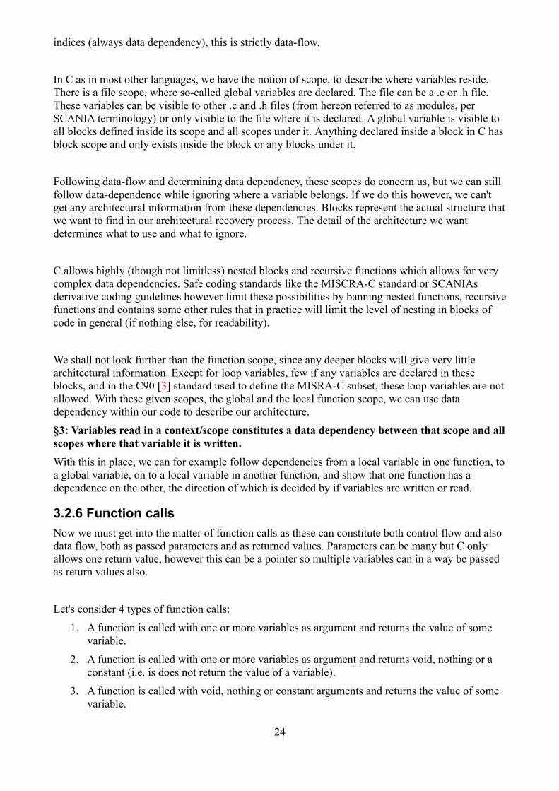
3.3.2 Description XML format specification (using XML 1.0)
The following nodes are available in the description format:
<root>
This node has no attributes and can contain variable and module nodes only.
<module>
Has attributes name, manager, path and calibration. The name is a unique string, path is a folder path in dotted notation, manager is the parent folder of the module. Calibration is an optional attribute that is Scania specific, and is set to ”yes” if the module has a calibration file.
<function>
Has attributes name, type_specifier, which is the return type, storage_class_specifier which is eitherextern or static and line which is the line number in the original (unpreprocessed) source code where the function definition starts.
A function can contain one parameter_list and one statement_list.
<variable>
This node represents a variable declaration, and is placed in the node that corresponds to the declaration scope where it was declared in the source code. Attributes are name, type_specifier, and optional array and pointer attributes which are set to “yes” and “*” respectively, if the variable is anarray and/or a pointer.
Variables can be declared in <root> (extern), <module> (static file-scope), <parameter_list> or in the first statement_list descendant of a <function> node (local variable).
<parameter_list>
This node contains variables which represent the parameters of the function where the parameter_list exists. They must be placed in the correct order.
<statement_list>
The statement_list node represent a C-block, and may contain variables, conditions_lists, calls, assignments or another statement_list. It has no attributes.
<condition_list>
A condition list is placed inside a <statement_list>. Everything inside that statement_list is dependent on the conditions in the <condition_list>. It has no attributes.
<condition>
Represents a condition and has the attribute name, which is a variable name. The <condition> is always inside a <condition_list>.
<assignment>
An assignment expression. This node has two attributes source and destination, which are strings with a variable name for the destination, and either a variable name or a constant number for the source. Assignments can exist inside a statement_list, or in a <module>.
If the assignment is in a module, it is an initialization of a global variable (and by the C-standard definition, this is always a constant). Because an initialization can also be the address of a pointer (using & operator in C), we allow variable names as source even in this case.
27
<call>
The call node represents a function call and can only be placed inside a <statement_list>. Attributes are function, which is the name of the function that is called, and return, which is the variable wherethe return value is written. It can also be the string void, if the is no return value.
<argument>
This node represents a function call argument, and can only be placed in a <call> node. Arguments must be in the correct order. It has one attribute “source” which is a string of comma-separated variable names or constant values. This is one part of the description XML not following the spirit of XML.
<return>
This node represents a return statement and can appear in any statement_list. By MISRA recommendations, return statements should preferable appear at the end of a function and only onceper function. It has one attribute “source” which is one variable name or constant.
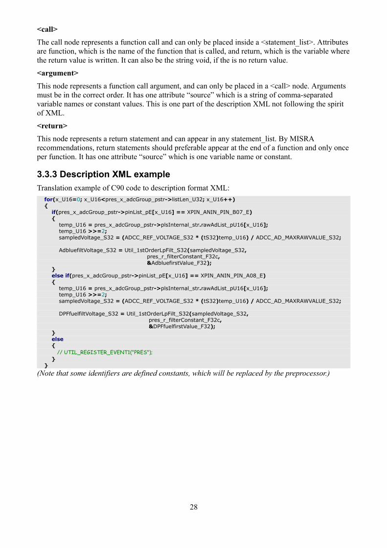
3.3.3 Description XML example
Translation example of C90 code to description format XML:
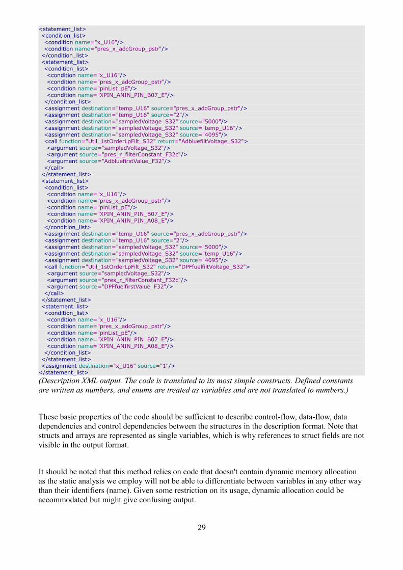
(Description XML output. The code is translated to its most simple constructs. Defined constants are written as numbers, and enums are treated as variables and are not translated to numbers.)
These basic properties of the code should be sufficient to describe control-flow, data-flow, data dependencies and control dependencies between the structures in the description format. Note that structs and arrays are represented as single variables, which is why references to struct fields are notvisible in the output format.
It should be noted that this method relies on code that doesn't contain dynamic memory allocation as the static analysis we employ will not be able to differentiate between variables in any other way than their identifiers (name). Given some restriction on its usage, dynamic allocation could be accommodated but might give confusing output.
29
3.4 Creating graphs
Now that we have our software description and our relational rules as defined above, we can begin to create our software graph. A natural way of representing data flow, control flow etc in a graph is by directed edges between nodes. To draw relational graphs of our software, given our newly produced architecture description XML file, we also have to select an appropriate level of abstraction which we want to display.
For C, as well as most traditional languages, there are a few abstraction levels given by the language itself such as functions, blocks, and modules. Given an abstraction level, we only need to draw things of higher abstraction. For example, if we choose to show only modules in the software, only relations between modules are show, not those that happen internally in the module.
When representing relations between nodes by edges, we can choose to display all relations of one path as one edge per relation or one edge per path and everything in between. As our target softwareis rather complex, we want to limit the number of edges, especially when our abstraction level is high, to improve readability of the graph.
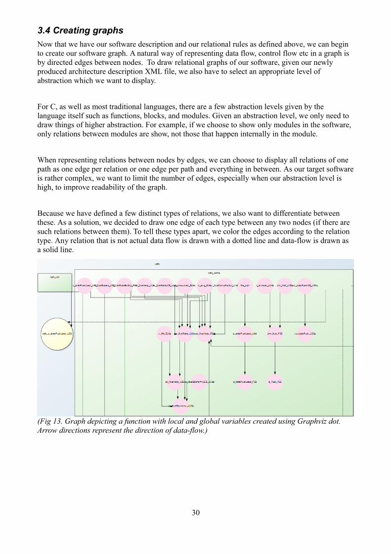
Because we have defined a few distinct types of relations, we also want to differentiate between these. As a solution, we decided to draw one edge of each type between any two nodes (if there are such relations between them). To tell these types apart, we color the edges according to the relation type. Any relation that is not actual data flow is drawn with a dotted line and data-flow is drawn as a solid line.
(Fig 13. Graph depicting a function with local and global variables created using Graphviz dot. Arrow directions represent the direction of data-flow.)
30
3.4.1 Edge and node styles, legend
All nodes and edges in the rendered graphs are given colors and style according to certain rules givea better understanding of the relational graph.
Module-level graphs:
Entity Color/style
Module Yellow rectangle.
Cluster Every cluster level has its own color, following a preset color scheme.
Assignment edge Solid black line.
Parameter passed in call Solid green line.
Value returned from function Solid red line.
Conditional dependency Solid purple line.
Parameter-less function call Solid blue line.
With data flow:
Module Starting point of data flow is purple, other points in the flow are red, modules not involved are yellow rectangles.
Assignment Data flow assignments are undirected.
Edges All edges have descriptive text labels for the data flow graph.Variable level graphs:
Entity Color/style
Module Blue rectangle.
Function Green rectangle when external, orange when static/local.
Variable Yellow circle. Local variables are small, static file-scope larger and external variables are the largest.
Parameter Beige/brown circle, same size as local variables.
Assignment edge Solid black line.
Parameter passed in call Solid green line.
Value returned from function Solid red line.
Parameter-less function call Solid blue line.
Assignment ownership Dashed black line. Shows which function made an assignment from a global variable.
Parameter passing ownership Dashed green line. Shows which function used aglobal variable as an argument in a call.
Return ownership Dashed red line. Shows which function returned the value of a global variable to a caller.
Conditional ownership Dashed purple line. Shows which function used a global variable as a condition
31
preprocessor.rb
ast_reader.rb
module_graph.rbgraph_builder.rb data_flow.rb
viewer.html
preprocessor.rb
ast_reader.rb
module_graph.rbgraph_builder.rb data_flow.rb
viewer.html
3.5 Graphviz graph layout and dot graph description language
Graphviz [31][32] is an open source graph layout tool which also has its own graph language called dot, as well as supporting other popular graph languages as input. It has a wide selection of graph layout engines which lays out graphs automatically according to different principles. The finished graph can then be rendered in a wide array of image formats.
(Fig 14. Toolchain stage 3. Create relational graphs, highlight andformat source code and render graphs into an SVG image.
graph_builder.rb creates graphs with variable-level abstraction, module_graph.rb with module-level abstraction.)
The dot layout engine in Graphviz is a directed layoutwhich is popular for software representation. It lays out graph by automatic clustering and ranks nodes in the graph by the direction of the edges going to and from it. This ranking can be used to form a software hierarchy if given the right input. The dot layout also supports manual clustering to use in combination with the automatic layout, which can be useful to hold things together which have a structural bond likevariables in a function for example.
If such a graph was laid out automatically and there were no relations between some of the variables, they might end up very far apart with no information left to show that they belong together.
If we have a predefined structure which we want to apply to our software to give a consistent view regardless of code changes, an undirected graph is more appropriate. Fdp is an undirected layout engine in Graphviz which also supports manual clustering. To use our predefined structure, we simply create a base template graph of empty clusters and position them according to our need, afterwhich we add all our nodes and edges just as we do with a directed graph. The layout engine then positions the nodes inside the clusters but leaves the clusters themselves unchanged.
3.6 Data flow graphs
(Fig 15. Toolchain stage 3. Create a relational graph from the data-flow relations flowing from one specific variable. Uses the same module-level abstraction as in module_graph.rb)
When representing data-flow in a graph, we generally want to display the data as it flows betweenvariables (or addresses if looking at the physical memory). For global variables that are visible in more than one scope, we would also like to see in which context the data flow happens, which generally means showing which function performed the operation that led to a certain data-flow.
32
In multitask systems, this is complicated by the fact that multiple tasks can read or write a variable independent of each other, causing apparent data-flow between tasks that might not be actual data-flow and just variable reuse.
Most real-time systems have some type of task-communication interface which handles synchronization, allocation of data, invalidation of data, queuing and so on. To visualize such data flow properly using the methods we have chosen, an implementation-specific solution would most likely have to be done.
In most Scania ECUs, since there is no preemption, such synchronization does not exist, and sharing of a variable between tasks actually implies data-flow between them almost every time. Thecommon data storage layer used in Scania software, RTDB, is simply a collection of global variables that can be manipulated through get and set functions. Reading and writing rights are given to task in the form of a global pointer to use for reading (const pointer) or writing. Because alldata-flow is done through trivial C-language constructs, finding this data-flow in an AST and displaying it is easy.
When drawing the actual graph, one can choose two different ways to represent variables, or a combination of both. A natural way to display them is as nodes, with the flow represented by the edge between them. Another way is to have nodes representing contexts, for example a function or a module and the edges between them represent data-flow between those contexts through a global variable or function call.
Pointers can be difficult to display when showing data-flow. A naive way is to treat it as a variable always (which in a sense is true), even when it is de-referenced. By doing this one need not worry about what the pointer points to at the moment. To find where the real data-flow went, we need to trace backwards in the data-flow of the pointer variable in find where is got its address. This of course becomes confusing if the pointer was actually assigned a value several times.
If we enforced a rule that all global pointers that never change their value are const, we could translate it by de-referencing it directly to the actual variable that it was pointing to. By doing this we could show the data-flow more directly. This has some downsides, for example we would then be able to break the description XMLs scope, and the required restriction might make a lot of existing code incompatible with the tool. Because of these issues, we choose not to implement such a feature at this time.
The actual data-flow is calculated by starting from a given identifier (a variable name). Every context (function body or global initializer in a module) of occurrence of this identifier is traced independently in a recursive fashion. When a data-flow to or from the identifier is found, a new recursive trace is made on the variable that was the source or destination of that data-flow operation. Special treatment is given to function calls, when parameters passed to a function can create a new backward data-flow back to the caller if for example a pointer was passed to the function and then de-referenced in the function call (when this pointer was not part of the data-flow originally).
33
Every trace is made to one variable in one given context. If a global variable is involved, we trace all contexts where it is written or read. At every trace, we mark the variable and context of in a checklist so that we don't have to visit it again. Eventually we should reach the end of the data-flow.In the case that we don't or that the data-flow is too complex, we have an option to impose an iteration limit to the trace, forcing the trace to stop once it has gone a specified number of iterations away from the origin. In the current version, structs and arrays create problems when tracing data-flow as every user of an array will get involved in a trace that only concerns a single index in the array. To work around this, the data-flow trace tool currently has an option to stop iteration when anarray is reached. This is a serious limitation and needs to be addressed.
(Fig 16. Part of a data flow graph showing flow between modules (boxes). The edge labels show the function call relation or the external variable used in the data flow. The purple box is the origin module for the variable whose data-flow we are tracing.)
int scale_function(int datavar1){ return scale_variable * datavar1;}
Tracing localvar1 by iteration:
1) localvar1 is found to be used twice in the code inside the context init_function.
2) Start a recursive trace on the initialization assignment ”localvar = 1234;” and the call “globalvar_1 = scale_function(localvar1);”
3a) 1234 is a constant, so the iteration ends.
3b) localvar1 is used as an argument for scale_function. We find the corresponding parameter variable in scale_function, datavar1, and start a new iteration in the context scale_function beginning at that variable.
4) datavar1 is returned, so we start a new trace in init_function from the variable where the return value is written. Here we need to keep track of where we called from, so that we can actually get back from the call.
5) global_var1 is a global variable, so begin a new trace of all the uses of this variable.
6a) global_var1 is assigned a constant, the iteration ends.
6b) global_var1 is written using a return value, all variables that appear in a return statement in the called function flow to it. We will therefore begin a new trace in scale_function tracing the variable scale_variable and datavar1 in this context.
7a) datavar1 has already been visited in this context, to we end the iteration.
7b) The variable scale_variable is a global variable, so we start a trace for all the uses of this variable.
8a) scale_variable is only assigned a constant value, the iteration ends.
8b) scale_variable is returned by scale_function, but we have already visited this context for this variable, so we end the iteration.
35
preprocessor.rb
ast_reader.rb
module_graph.rbgraph_builder.rb data_flow.rb
viewer.html
3.7 Architectural graph browser/viewer
(Fig 17. Toolchain stage 4. A common graph viewer for all graphs, including a source viewer, zoom/pan and some simple edge abstraction capabilities.)
After creating our graphs in Graphviz, we render them in SVG (Scalable Vector Graphics) which allows some useful features such as unlimited scaling (since its a vector format), hyperlinks, text labels etc. After this is done, we transform the SVG using an XSL style-sheet to give the graph a better and uniform appearance. The actual displaying of the SVG image is then done in a web browser.
(Fig 18. Viewer application showing data-flow of one variable through the whole ECU software. The software structure is represented by the clusters and sub-clusters containing the nodes. To the right is the source code browsers which shows the source code of the module currently selected.)
36
To connect the graph to the source code, the whole source code is transformed into prettified HTMLfiles with embedded highlight annotation and HTML anchors to allow jumping to a given point in the code. These annotations are created by performing regexp queries on the source code for all identifiers found in the AST (for highlighting variables in source code) and a complex regexp for identifying function definitions in the source code.
JavaScript program SVGPan is used to allow the user to zoom and pan the graph in the browser. Because we use the SVG format, it is technically possible to manipulate the graph arbitrarily in the browser, but so far we only use a static graph. Every node of the graph is given a hyperlink address that points to the corresponding source code HTML-file, along with the highlight annotation identifier (usually a variable name or function name). To show only relations between a selection of graph elements, the graph viewer can strip the SVG image of all edges not matching certain criteria.This is done by simply finding these edges in the SVG and setting them to be invisible, after which the browser itself redraws the image. The physical graph file is left untouched.
The viewer is implemented using only client-side scripting and HTML. A more dynamic viewer would most likely require the use of some server-side applications to allow reading of files, using advanced script languages etc (such as Ruby). As of now, the viewer can only be used as a viewer, itcannot generate new graphs itself (this is done by the ruby-script toolchain).
37
38
4 Evaluation of resultsThe implementation phase of this thesis produced 3 tools used to produce different variations of architecture views. All these tools share the same output format and can all be viewed in a single viewer application or any other viewer supporting SVG. Using existing ECU software from Scania, we will now evaluate these tools to find if they can be useful in the development process. Lastly we will look back at the standard and discuss what is needed to meet the requirements of the ISO 26262standard as stated earlier.
4.1 Variable-level abstraction view
In this architecture view, variables are represented as nodes, local variables are allocated in functionclusters, which are allocated in module clusters along with static global variables. External variablesare placed outside all clusters at the top level of the graph. This gives a very complete view, but sometimes too detailed. The dot layout engine is used which yields a hierarchical graph where globally shared variables and function calls are used to rank nodes and clusters. Because it uses the dot layout and because of the level of detail, this view is limited to a handful of modules due to Graphviz limitations/bugs. Modules to be included in the graph currently have to be selected manually when the graph is generated.
The graph generated here only uses structure inherent in the source code itself, and does not use anyfolder structure or other metadata/scaffolding to cluster the top level graph. The time it takes to generate a graph increases greatly with increased complexity/size of the modules included in the graph.
The resulting graph can be useful when looking at a limited set of modules. When including modules containing different helper functions that are called by tasks, all uncalled functions will still take up space. The same goes for unused global variables (unused by the selected modules). To get around this, options were added to the graph builder when generating the variable-level graphs to hide things that seem to be unused.
(Fig 19. A variable level graph. A module (blue) containing 3 functions (green and beige boxes) and an external function in another module being called by one of them (lower left corner). The graph needs a large resolution display or large printout to display properly.)
39
(Fig 20. The same graph, with a function selected. The source window highlights the selected function in the source code.)
(Fig 21. An external function (green box) was selected. In the top left window we see a complete listof all modules that make reference to this function and a link to their respective source file.)
4.2 Module-level abstraction view
This view uses a given structure to create clusters and then only adds edges between nodes. Becauseof the abstraction done, it is possible to fit a whole ECU software project into a single graph while still keeping it at a manageable size. Relations inside modules are not drawn at all leaving only external function calls and sharing of external global variables as relations in the graph.
The complete graph of an entire ECU is created, so for this graph there will be no real problems with any unused modules, and if those exist (dead code) they will not take up much space anyway.
On the other hand, the number of relations between modules may be overwhelming. Thankfully we are able to selectively show relational edges for only those modules we are interested in.
40
(Fig 22. Co-ordinator ECU software. The cluster in the top right has been selected, the graph only showing relations to and from the modules inside that cluster. Every edge color represent a differenttype of relation. The edge arrow represents the direction of the relation, usually data-flow or control flow)
4.3 Data-flow tracing view
The data-flow view uses the same structure as the module-level graph. Only the flow passing between modules is shown, but all internal data-flow is of course included when tracing the data as we would otherwise loose all connections once data is written to a local variable. The tracing tool currently has some limitations when starting a trace of a local variable (if the name is not unique, allvariables with the same name will also be traced) but will otherwise work for any variable. The limitations regarding arrays and struct as mentioned before are a big problem and this tool will be oflimited use until they are addressed. How successful one is in tracing data-flow at the moment depends greatly on how the code is written and how variables are stored.
41
(Fig 23. Data-flow tracing of a variable. The edges are annotated with either variable name or function call and argument name. Green edges are arguments passed in function calls and red edges are data returned by the function.)
Assignments are currently not given direction and therefore we trace in both directions of the data flow. This can certainly be improved if pointer de-referencing can be handled correctly, allowing the tracing of data flow in only on direction at a time, forwards or backwards.
4.4 ISO 26262 requirements evaluation
The software architectural design, which is constrained by requirements in clause 7.2, 7.4 of the standard, can partially be produced by the tools developed in this thesis. Reiterating again clause 7.2:
“The software architectural design represents all software components and their interactions in a hierarchical structure. Static aspects, such as interfaces and data paths between all software components, as well as dynamic aspects, such as process sequences and timing behavior are described.”
Similar requirements are set for software units. The static aspects mentioned here can be said to be fulfilled. The same goes for enforcement of limited complexity (Clause 5 table 1). The dynamic partof course is lacking, alas this is out of the scope of this thesis.
The general requirements regarding analyzing control and data-flow can be said to be partially fulfilled. The question arises here of course how this is supposed to be documented. A reasonable assumption is that this is only to be applied on an ISO component (equivalent of Scania manager or module). Low level control-flow however is not addressed, that is, control-flow within functions. However this is probably not meant to be addressed using a graphical approach but simply means doing some coverage testing which again is a dynamic activity.
The tools can produce views that far exceed the detail level of any architectural documents Scania currently has, but will certainly have to improve further to comply with the standard in all respects.
42
As it's not yet clear exactly how the required documentation is going to look like, it's hard to make afair evaluation. A lot will likely be decided by the industry as a whole and possibly influenced by legislators. At the moment, there is not much available in terms of best practices for such documentation. As a consequence, our approach may have to change to accommodate future interpretations or revisions in the standard.
The requirement of using an unambiguous graphical representation we classify as partially fulfilled,but there is certainly room for improvement there.
4.5 Future improvements and feasibility
There are several improvements to be made to the implementation with the most important being support for struct fields and array indexing. While struct fields are trivial to add, array indexing would require enforcing additional constraints on C language usage in order to handle single array indices properly while still only using static analysis. Iterating over arrays will have to be restricted.With the current Scania codebase, supporting individual array indices is necessary to be able to display data flow, as the flow will otherwise explode in complexity every time an array is reached inthe flow (and make the results unusable).
Other that this, function pointers are still not supported properly, but no effort was put into finding if supporting them would be difficult or not. As they are not widely used outside ComP, the implementation works reasonably well without them. The current description XML format can not represent function pointers and probably needs to be changed in order to support such constructs. The same goes for function calls used as parameters or function calls as return values. These can notbe represented in the description XML because they rely on an implicit temporary data storage which conflicts with the formats rule that data is always stored in a variable that has a name and a scope where it is declared.
Variable pointers and pointer de-referencing could be represented better than it is at the moment. Replacing de-referenced pointers with an assignment to the pointed-to variable in the description XML would seem like a natural choice, but also brings out other problems such as the format not respecting variable scopes, ambiguous pointers such as pointers parameters where it would be impossible to know where they point to. It's not entirely clear how to go forward with pointers, but programming standards call for restriction on their use and this is an easy way out. In the meantime,a good start would be to simply include de-referencing as an attribute of an assignment so that the information can be used once we know what to do with it. For the data-flow case, this information is easily exploitable.
Since relations are limited to one of each type (except for the data-flow graph), it could also be useful to store a list of relations represented by a single relational edge with a link to the line in the source code where the relation can be found. This should be possible to implement without any major changes to the current design.
We believe that it is feasible to support parts of ISO 26262 using these tools given above mentionedimprovements and restrictions on the source code. In some ways, the tools deliver more detailed information than the standard requires. If they meet the standard or not is a matter of interpretation of the standard. To fully fulfill the standard, all tools used in development must meet the same ASILlevel as the software that is developed, so to support software development other than QM, the tool
43
has to be developed according to the requirements on software tools as set forth in part 8 of the ISO 26262 standard.
4.6 Conclusion
Compared to the available alternatives, taking the path of architecture recovery has cost advantages in the short term, and is certainly the most conservative way to comply with the ISO 26262 standardsince it will hopefully allow most legacy code to remain unchanged.
Alternatives such as model based development, which the standard also favors, have advantages such as easy development and automated verification. The advantages of hand-written C-code in terms of speed and low memory usage quickly disappears as standards restrict language use to a point where the performance is just as bad as generated code. And while a code generator is free to improve itself, the hand-written code is hindered by standards.
But as long as code generators produce C-code, our method will still be valid for both hand-written and generated code, which will allow a great deal of flexibility for the programmer.
44
5 Licensing and acknowledgmentsThe implementation part of this thesis used several open source programs. This is a list of the licenses of these programs:
Program name Author License/terms
mcpp portable C preprocessor Kiyoshi Matsui BSD-style
srcML src2srcml Michael L. Collard and Huzefa Kagdi GPL
Graphviz AT&T Labs Research (and others) Eclipse Public License
google-code-prettify Mike Samuel (and others) Apache License 2.0
The author also wishes to thank Mattias Nyberg, Josip Pantovic and Martin Pruscha, whose suggestions were very helpful when researching this subject and developing the architectural recovery toolchain.
45
46
6 VocabularyADC
Analog to digital converter.
AST
Abstract Syntax Tree. Source code can be represented as a tree of nodes containing the structure of the code syntax. Variations which may be allowed in the actual source code suchas indentation, whitespaces etc are not present, only the deconstructed syntax. There are variations of abstract syntax trees such as selected ASTs which may chose to only include certain parts of the full language syntax. The convenient tree structure makes it easy to traverse through source code.
BlockBlock is a portion of code encapsulated by curly brackets {}. Each block has its own scope and local variables can be declare in each scope which will be unavailable outside the block.Keeping variables in as limited scope as possible is generally considered a safe practice since it keeps other parts of the program from modifying the data by accident.
CAN bus
Controller Area Network is a simple networking protocol made popular in automobiles. It is used with 2-wire network buses with two or more nodes connected to each bus. CAN was made popular due to the low-cost and high availability CAN controller hardware. Transfer speeds for data is slow compared to other protocols such as Ethernet, and gets worse when the wire lengths increase due to signal propagation delays.
Condition
A condition in C is evaluated until a Boolean result is reached. The order of evaluation of complex expressions can sometimes be hard to understand by just reading. MISRA makes restrictions on the complexity of such expressions and does not allow them to be written in away that relies on the order of evaluation unless in very simple cases. This is particularly important for expressions including volatile variables where one variable in the expression may change in the middle of the evaluation.
Conditional statements in C/C++ are ternary, if, switch, while, do-while, for. While, do-while and for allows the condition to be empty making an infinite loop that has to be broken out of in some other way
const
A variable declared const (constant) should not be allowed to be written to, and consequently a const pointer should not be allowed to be de-referenced and then written to. It is the compilers responsibility to make sure that consts are not written to. It does not have a physical significance in the actual compiled program, that is, the address where the variable is stored is not necessarily read-only.
De-reference (of pointers)
The de-reference operator returns the value at the address pointer to by a pointer. In C, the de-reference operator is * for pointers and -> for pointers to structs. In the special case of arrays the notation variable[index] is used in a similar way. This is equivalent to writing *(variable + index) where variable is the array name. Symbolically, the variable name of an array is a pointer to the first index of the array.
47
DMA
Direct Memory Access and closely related features such as DTC (data transfer controller) is a hardware feature use in many computers and embedded systems. It allows hardware devices to transfer data to or from memory without interrupting the CPU. DTC is a similar feature that can transfer data from one memory address to another without CPU interaction.
The C language and compilers are unaware of any such data transfers, so care must be taken when handling data written to or read from by a DMA controller. This is a case when variables are usually qualified as volatile, to tell the compiler that their content may change unexpectedly.
ECU
Electric Control Units use sensors and actuators to control some function such as engine control for example. These units have evolved in the last decades from analog electronics to digital electronics and now becoming more and more software based. ECUs today are usually a type of embedded system consisting of a CPU or microcontroller, AD/DA converters (connecting sensors and actuators) and communication interface (like CAN).
Enum
Enumerators in C is an integer of a set range that have an identifier associated with each integer in the range. It's a convenient way to use words in place of constants to increase codereadability.
Extern
Externally declared variables and functions in C are globally accessible everywhere in the program. This make programming easier but creates many possibilities for programmer errors. The use of global variables is popular in embedded systems since it can save on memory and code size, but is discouraged by standards such as MISRA and ISO 26262.
IDE
Integrated Development Environment. IDEs are text editors with additional features such as syntax checking, version management, debugging, etc. Advanced static analysis is usually not part of an IDE but some static analysis tools supply add-ins for major IDEs such as Microsoft Visual Studio, Eclipse etc.
InitializerAn initializer initializes a variable, giving it an initial value. An initialization of a variable is usually done when it is declared, or at the beginning of a for loop when the variable is used as an iteration variable.
Preemptive (scheduler)A preemptive scheduler is a scheduler that is allowed to interrupt the current running task before it has finished when making a context switch.
RTOS
Real-Time Operation System. An OS that is required to keep time constraints set for the given task-set it schedules. Most ECUs use an RTOS.
Struct
Struct is a defined data structure which is defined by the programmer to contain a collection of variables of different types. Each variable in the struct is given an identifier which can be used to access it. The identifier is called a member. It is the struct equivalent of the array index.
48
UML
Unified modeling language is a popular modeling language used extensively in software engineering. UML is now part of the ISO 19501:2005 standard.
XML
Extensible Markup Language. A markup language that everyone should be familiar with.
XPath
XML path language. This is one of a few query languages used to create queries for searching through an XML document in an efficient manner. A query can return one or many results matching the query which the user can then iterate over. This has great advantages over accessing nodes in XML documents by hard paths and much easier than iterating through documents manually and comparing nodes at every step. A popular open source implementation of XPath is available in libxml2 [34].
49
References
1. ISO 26262:2011, “Road vehicles - Functional safety”, first edition, 2011
2. ISO 26262-6:2011, “Production development at the software level”, first edition, 2011
4. MISRA-C:1998/2004/2012, “Guidelines for the use of the C language in critical systems”, The Motor Industry Software Reliability Association, published: 1998, 2004, 2013 respectively
5. IEC 61508, “Functional safety of electrical/electronic/programmable electronic safety-related systems”, International Electrotechnical Commission, 1998-2000
8. “Static Analysis Based Software Architecture Recovery”, Jiang.G, Yuehong.L, R.Pamula, ICCSA2006, LNCS 3982, pp. 974-983, 2006
9. “The program dependence graph in static program testing”, Bogdan Korel, Information Processing Letters 24 (1987), 103-108.
10. “Evaluation of Flow graph and Dependence Graphs for Program Representation”, V. Arora, R.K. Bhatia, M. Singh, IJCA (0975-8887) Volume 56 No.14, October 2012
11. “Towards A Process-Oriented Software Architecture Reconstruction Taxonomy”, D. Pollet, S.Ducasse,L.Poyer,I.Alloui,S.Cîmpan, H.Verjus, 11th CSMR, 0-7695-2802-3/07, IEEE, 2007
12. http://wiki.eclipse.org/Linux_Tools_Project/Callgraph/User_Guide, Eclipse Linux Tools Project,downloaded 2013-03-28
13. “Hardware dependent Software, Concept, Tools and Applications”, Wolfgang Ecker, Wolfgang Müller, Rainer Domer, 2009, Springer, 67- 94
18, 19, 20. “Safer C: Developing Software for High-integrity and Safety-critical Systems”, Les Hatton, 1995, McGraw-Hill, ISBN 0-07-707640-0, p.38, p.43, chapter 5 respectively.
21. “C-Programming rules for embedded software in vehicle systems”, REVE12015, Bo Neidenström, Scania internal, 2012
22. ”Automated Data Flow Visualization Through Static Analysis of Source Code”, Martin Pruscha,Josip Pantovic, 2013, Master thesis
23. “Using Automatic Clustering to Produce High-Level System Organizations of Source Code”, S. Mancoridis, B.S. Mitchell, C. Rorres, Y. Chen, E.R. Ganser, IWPC '98. Proceedings, 6th International Workshop on Program Comprehension (45-52), 1998
27. ”JSF Air Vehicle - C++ Coding Standards”, Revision C, Lockheed Martin Corporation, 2005,http://www.jsf.mil/downloads/documents/JSF_AV_C++_Coding_Standards_Rev_C.doc, downloaded 2013-05-13
28. ”JPL Institutional Coding Standard for the C Programming Language”, Jet Propulsion Laboratory, 2009, http://lars-lab.jpl.nasa.gov/JPL_Coding_Standard_C.pdf, downloaded 2013-05-13
29. “Lint, a C Program Checker”, S. C. Johnson, Bell Laboratories, Computer Science Technical Report Number 65, 1978
30. “Lightweight Transformation and Fact Extraction with the srcML Toolkit”, M. L. Collard, M.J. Decker, J.I. Maletic, SCAM 2011 (173-184)
31. “Drawing graphs with Graphviz”, Emden R. Gansner, 2011, http://ww.graphviz.org, downloaded 2013-05-14
32. “Using Graphviz as a Low-cost Option to Facilitate the Understanding of Unix Process System Calls”, M. Riesco, M. D. Fondón, D. Álvarez, Electronic Notes in Theoretical CS 224 (89-95), 2009
33. “XML - begreppen och tekniken”, Gustaf Liljegren, Studentlitteratur, 2003
34. “The XML C parser and toolkit of Gnome - libxml”, http://xmlsoft.org, downloaded 2013-05-17
35. “Semantic similarity-based grading of student programs”, Wang Tiantian, Su Xiaohong, Wang Yuying, Ma Peijun, Information and Software Technology 49, 99–107, 2007