Design Your Ow n Regulated POWER SUPPLY INTEGRATED-CIRCUIT VOLTAGE REGULATORS have been around r quite a while, but they have been expensive and have needed loʦ of "outboard" pans to get them to work. Tay, there's a new breed of volt- age regulato here. These are low in cost ($2-5 in singles), very easy to use, and take very few ouʦide additional pans. Some directly handle up to 1 of an amp; othe easily handle an amp or more with etemal pass transisto. Some are fied-value out- puʦ; othe are variable. Some are dual pai that give you two output voltages (one sitive, one negative) out of the same package. Why bother to regulate a wer sup· ply? For oפne. the hum eentially dis· appea. Besides a rock-stable output volt· age that is independent of temperature, line, or load variations. most designs are also shon-circuit proof, shutting down or urrent limiting automatically. This protecʦ the regulator and the supply against dam· age om shons, and the current limiting will usually (but not always!) al protect the load from damage caused by wrong biing or polarity mumps. Finally, a regu- lated power supply may actually be chea p er than an unregulated one, particularly if you need ve low hum on the supply lines. This happens because you can usually use a much smaller filter capacitor. For instance, if you wanted a 5-volt, 2mA supply with le than 20 millivolʦ of ripple, single ca- pacitor "brute-force" filtering might take around a 80,0 11F capacitor. With a regu· lator, you might design a power supply with a 16-volt output and four volʦ of peak to peak pple, and do the job with a (11F capacitor, with the regulator absorb· ing the "lumps" and giving a smooth out- put. Often times, the difference in capacitor cost is greater than the price of the regu- lator, pticularly if the capacitor makes the ce bigger, and regulated supplies can be cheaper than unregulated ones. Of coue, the problem with any power supply design is figuring out what size and voltage transfoer you need, where to get it. what size capacitor to use, and how much fusing to provide. After that, we can New IC regulators are so inexpensive and easy to use that you can build a regulated, short-circuit proof power supply for less than the old unregulated kind tack a regulator onto the output. Start with an unregulated power supply Let's aume you're interested in out- put voltages that are low compared to the 117-volt power line, and are interested in currents between 50 mA and an ampere or two. Let's also assume you are working with a 60-henz, single-phase power line. as usual. For this panicular type of power re- quirement, the transformer-coupled, full· wave capacitor-input circuit of Fig. I is rec- ommended. The transformer drops the voltage to a chon value and pdes safety isolation. When its anode is sitive diode DI con- ducʦ and charg�s capacitor C. On the net half-cycle. diode D2 conducʦ and charges capacitor C. If there isn't too much load on the capacitor, it dœsn't discharge very much between cycles and so the conduction time of each diode tus out to ve short. Ve high currents flow ve brierly during the diode conduction time and the current to the capacitor is delivered in nar· row spikes. The amount of the current and the time width of the spik deפnd on the load, the capacitor. and the inteal resis- tance of the transformer, but the time spac- ing between the spikes is precisely half of a < henz power line cle, or a time period of 8.33 milliseconds. Figure I also shows the waveform at the capacitor and the load. It is eentially a fixed de value om which a sawtooth waveform is subtracted. The frequency of the sawtooth is 120 henz (for a full-wave rectifier), and iʦ depth depends on how ft the capacitor diharges. The greater the load for a given size capacitor, the more the capacitor can discharge between the charging current spikes and the higher the sawtooth pple. There are two other poible circuits, the half-wave single diode one, and the ll-wave one using a single (untapped) transer winding and a bdge rectifier. The half-wave circuit takes twice the ca- pacitor size and h twice the peak diode current. It also takes a bigger transer as unbalanced currents and a resultant de !low through the transrmer windings. The full-wave circuit takes ur diodes instead of just two and presents an additional diode drop between load and transrmer. Besides this, you can only get one voltage from any given winding. while the Fig. I circuit can easily get you several voltages since the transformer center tap is grounded. Thus, unle you have a good rean not to, stick with the center-tapped. OUTPUT VOLTAGE � 8.33ms J- F Tl Dl D2 GREEN FIG. 1-FULL-WAVE POWER SUPPLY with ca- pacitor-Input lllter Is a go choice lor a low- volta regulated supply. Regulator Is added between cacitor and output. 0 1.5 > 1.0 c· 0 � . 5 0 0 BASED ON 1N40 SERIES DIODE AND lOX PEAK CURRENT. .2 .4 .6 .8 LOAD CURRENT, AMPS 1.0 FIG. 2-OLTAGE DROP ACROSS SILICON DIODE can aroximat lrom l• cha II you not have data on your die. 54 RADIO-ELECTRONICS • DECEMBER 1973 w mPrirnrnrliohistorv rom
Transcript
Design Your Own Regulated
POWER SUPPLY INTEGRATED-CIRCUIT VOLTAGE REGULATORS have been around for quite a while, but they have been expensive and have needed lots of "outboard" pans to get them to work. Today, there's a new breed of voltage regulators here. These are low in cost ($2-5 in singles), very easy to use, and take very few outside additional pans. Some directly handle up to 1.4 of an amp; others easily handle an amp or more with elltemal pass transistors. Some are filled-value outputs; others are variable. Some are dual pairs that give you two output voltages (one positive, one negative) out of the same package.
Why bother to regulate a power sup· ply? For openers. the hum essentially dis· appears. Besides a rock-stable output volt· age that is independent of temperature, line, or load variations. most designs are also shon-circuit proof, shutting down or .current limiting automatically. This protects the regulator and the supply against dam· age from shons, and the current limiting will usually (but not always!) also protect the load from damage caused by wrong biasing or polarity mumps. Finally, a regulated power supply may actually be cheaper than an unregulated one, particularly if you need very low hum on the supply lines. This happens because you can usually use a much smaller filter capacitor. For instance, if you wanted a 5-volt, 200-mA supply with less than 20 millivolts of ripple, single capacitor "brute-force" filtering might take around a 80,000 11F capacitor. With a regu· lator, you might design a power supply with a 16-volt output and four volts of peak to peak ripple, and do the job with a 400-11F capacitor, with the regulator absorb· ing the "lumps" and giving a smooth output. Often times, the difference in capacitor cost is greater than the price of the regulator, particularly if the capacitor makes the case bigger, and regulated supplies can be cheaper than unregulated ones.
Of course, the problem with any power supply design is figuring out what size and voltage transformer you need, where to get it. what size capacitor to use, and how much fusing to provide. After that, we can
New IC regulators are so inexpensive and easy to use that you can build a regulated, short-circuit proof
power supply for less than the old unregulated kind
tack a regulator onto the output.
Start with an unregulated power supply
Let's assume you're interested in output voltages that are low compared to the 117-volt power line, and are interested in currents between 50 mA and an ampere or two. Let's also assume you are working with a 60-henz, single-phase power line. as usual. For this panicular type of power requirement, the transformer-coupled, full· wave capacitor-input circuit of Fig. I is recommended.
The transformer drops the voltage to a chosen value and provides safety isolation. When its anode is positive diode DI conducts and charg�s capacitor C. On the nellt half-cycle. diode D2 conducts and charges capacitor C. If there isn't too much load on the capacitor, it doesn't discharge very much between cycles and so the conduction time of each diode turns out to be very short. Very high currents flow very brierly during the diode conduction time and the current to the capacitor is delivered in nar· row spikes. The amount of the current and the time width of the spikes depend on the load, the capacitor. and the internal resistance of the transformer, but the time spacing between the spikes is precisely half of a 60 henz power line cycle, or a time period of 8.33 milliseconds.
Figure I also shows the waveform at the capacitor and the load. It is essentially a fixed de value from which a sawtooth waveform is subtracted. The frequency of the sawtooth is 120 henz (for a full-wave rectifier), and its depth depends on how fast the capacitor discharges. The greater the load for a given size capacitor, the more the capacitor can discharge between the charging current spikes and the higher the sawtooth ripple.
There are two other possible circuits, the half-wave single diode one, and the full-wave one using a single (untapped) transformer winding and a bridge rectifier. The half-wave circuit takes twice the capacitor size and has twice the peak diode current. It also takes a bigger transfonner
as unbalanced currents and a resultant de !low through the transformer windings. The full-wave circuit takes four diodes instead of just two and presents an additional diode drop between load and transformer. Besides this, you can only get one voltage from any given winding. while the Fig. I circuit can easily get you several voltages since the transformer center tap is grounded. Thus, unless you have a good reason not to, stick with the center-tapped.
OUTPUT
VOLTAGE � 8.33ms --J J-
F Tl Dl
D2
GREEN
FIG. 1-FULL-WAVE POWER SUPPLY with capacitor-Input lllter Is a good choice lor a lowvoltage regulated supply. Regulator Is added between capacitor and output.
Vl 1-...J 0
1.5
> 1.0 c.· 0 er Cl � .5 0 Cl
0
BASED ON 1N4000 SERIES
DIODE AND lOX PEAK
CURRENT.
.2 .4 .6 .8
LOAD CURRENT, AMPS
1.0
FIG. 2-\IOLTAGE DROP ACROSS SILICON DIODE can be approximated lrom lhl• chart II you do not have data on your diode.
54 RADIO-ELECTRONICS • DECEMBER 1973
www ::imP.rir.::inrnrliohistorv r.om
two-diodes, full-wave, capacitor-input circuit of Fig. I.
Some numbers There is no obvious "one-to-one" rela
tionship between the transformer voltage and the output voltage. You do not get 6.3 volts of de output from a 6.3-volt centertapped-transformer, or 12.6 volts from a 12.6 one and so on. While the game isn't quite this simple, it is easy to calculate the voltages you need for a given output.
Let's try the calculation "frontwards" first. Suppose you had a 6.3-volt rms center-tapped transformer, and to keep things simple, suppose further that the reR1Jlario11 of the transformer itself is very good, which is another way of saying the transformer can handle the load we want it to.
Each half of the 6.3 volt winding will be providing half of 6.3 volts or 3.15 volts. This is the rms ac value. We need to find the peak value, for this is what charges the capacitor through the diode. The peak value is 1.41 times the rrns value or 3.15 x 1.41 = 4.45 volts. (Note you can "speed math" this calculation by taking one-tenth the rms voltage, doubling it, doubling it again, and then adding the original voltage to it.)
If the diodes were perfect, we'd get a capacitor voltage of 4.45 volts. The diodes have a conduction drop, and quite a bit more than you might expect, sinct. when they are conducting, they carry ten to twenty times the average load current. Rcmem ber that the diodes only conduct bndly. If they are only on for II 10 the time, they have to conduct ten times the current the load needs.
The accurate way to find the voltage drop is to use a data sheet for the particular diode you are using and calculating the actual conduction angle, which is a pain. Figure 2 gives you a curve that is exactly valid for a IN4000 series diode and a conduction time of I/ 10 a complete cycle. This is close enough so long as you are using any reasonable silicon power diode. From Fig. 2, we see that the drop will be around a volt for lower currents; let's use this fi��
ure. The diode drop subtracts from the available voltage, so the voltage across the capacitor is 3.45 volts. This is a peak value, from which we subtract the ripple voltage.
Figure 3 is a chart that relates the transformer voltage to the filter capacitor voltage for several values of diode drop. Use the chart directly or else use the following rules:
To find the peak output voltage: I. Start with the transformer secondary rms voltage 2. Divide by two to get the centertapped voltage 3. Multiply this by 1.4 to get the peak value 4. Subtract the diode drop, estimated from Fig. 2, or subtract ( volt for lower current operation.
To find the transformer voltage: I. Start with the peak capacitor voltage. 2. Add the diode drop 3. Multiply by 0.707 to get the rms value 4. Double this for the center-tapped rms value
It turns out that you always design for much more output voltage than you really need if you are using a regulator. The regulator has a minimum dropout voltage above its output it needs for proper operation. The maximum voltage is limited by regulator breakdown or power dissipation. We'll see more on this in just a bit, but first.
What size capacitor? The size of the filter capacitor and the
maximum load current determine the amount of sawtooth ripple you get. The accurate analysis of this is also a pain. We can make a very good approximation if we assume our ripple sawtooth voltage recharges very fast and decreases linearly. This both simplifies the math and puts us on a conservative side of things.
With this simplification, the relationship between the load current and the capacitor size is given by:
VALID FOR FULL WAVE 60 H E RT Z ONLY!
.5 LOAD CURRENT, AMPERES
where: V1011<1 =Load voltage, volts R1oa<1 =Load Resistance. ohms .l V =Ripple in volts C =Capacitance in farads
1.0
Even this is a messy and confusing formula. Figure 4 gives it in graphical form. A simple way to forever remember how to calculate capacitor size is:
Use an 8000-µF capacitor and the ripple In VOL TS will Equal the current In AMPS.
Use an 8-µF capacitor and the ripple In VOL TS will Equal the current In MILLIAMP$.
Double the capacitor to halve the ripple and so on. For instance, with our rule, a 4000-µF capacitor gives us I volt of ripple at 500 mA, and so on. Rules-ofthumb like we are giving you may not be exactly accurate, but they are quick, easy, and they work. And that's all we need to worry about.
Picking the parts Th.e choice of a capacitor isn't too
hard to make-use the best quality electrolytic you can afford, of a voltage rating at least equal to, and preferably double your output voltage. Ordinary computergrade aluminum electrolytics are a good choice. Tantalum capacitors are an expensive luxury unless you happen on to some surplus units or are going to put your circuit into orbit. Silicon power diodes are wugh and readily available. Use the IN4001 or IN5060 or their surplus equivalents for the I-amp or less applications. For higher currents, use the 3-ampere diodes such as a IN5624 or a 1N4721 or something larger.
These diodes run very hot. Their leads should be short and routed to some sort of heat radiator such as lots of foil on a PC board, or a large terminal strip. The heat removal process is mostly by conduction-
Load current =RVioad load
Cx.'l V out the leads. For long diode life, provide 8.33x 10⁻³ some place for this heat to go. Phenolic PC
DECEMBER 1973 • RADIO-ELECTRONICS 55
www.americanradiohistorv.com
boards may char under direct heat exposure, so the epoxy-glass versions are preferred for power supply work. Also be sure that a power diode doesn't end up in direct contact with an electrolytic or the heating can shorten the capacitor's useful life.
The maximum voltage across the diode is twice the output voltage. Use a PIY rating at least double this. If in doubt, go to a 200- or a 400-PIY unit; they don't cost that much more and may be easier to get.
This brings us back to the transformer. If you possibly can, use a stock filament transformer, as these are inexpensive and easy to get. Unfortunately, these often tum out to be rather large, particularly if you are working with compact gear, and offer only a limited choice of voltages.
One source of transformers I've found extremely handy-at twice the usual filament transformer cost-is Signal Transformers, I Junius Street, Brooklyn. New York, 1 12 12. They have an incredible variety of stock very small to enormous transformers, some of which mount directly on a PC board without any hardware. For instance, a PC-mount IO-Vet transformer that can handle 120 mA, measures I W' square by 11 " long and sells for around $4.37, plus postage.
The input fuse and third wire ground on the supply is simply good practice. Use a slow-blow fuse whose amperage is above l/50th the load power. For instance. a 5-volt. I-amp unregulated supply provides 5 watts at full load. Use a 5/50=0. I ampere unit. The actual current may be found by dividing the load power and the trans-
BLK
?4 WHITE
GREEN
�
Tl D1 R LOAD(+)
+ \1 C+ I l
RLOADH FIG. 5-NEGATIVE SUPPLY may be added to basic supply. The transformer curren.1 rating must be high enough to handle both loads.
FROM TRANSFORMER
+
former losses by the line voltage and then making some power factor adjustments and then adding a safety factor. The I /50th load power current (measured at the capacitor-not the regulator) formula is a lot quicker and gives the same result.
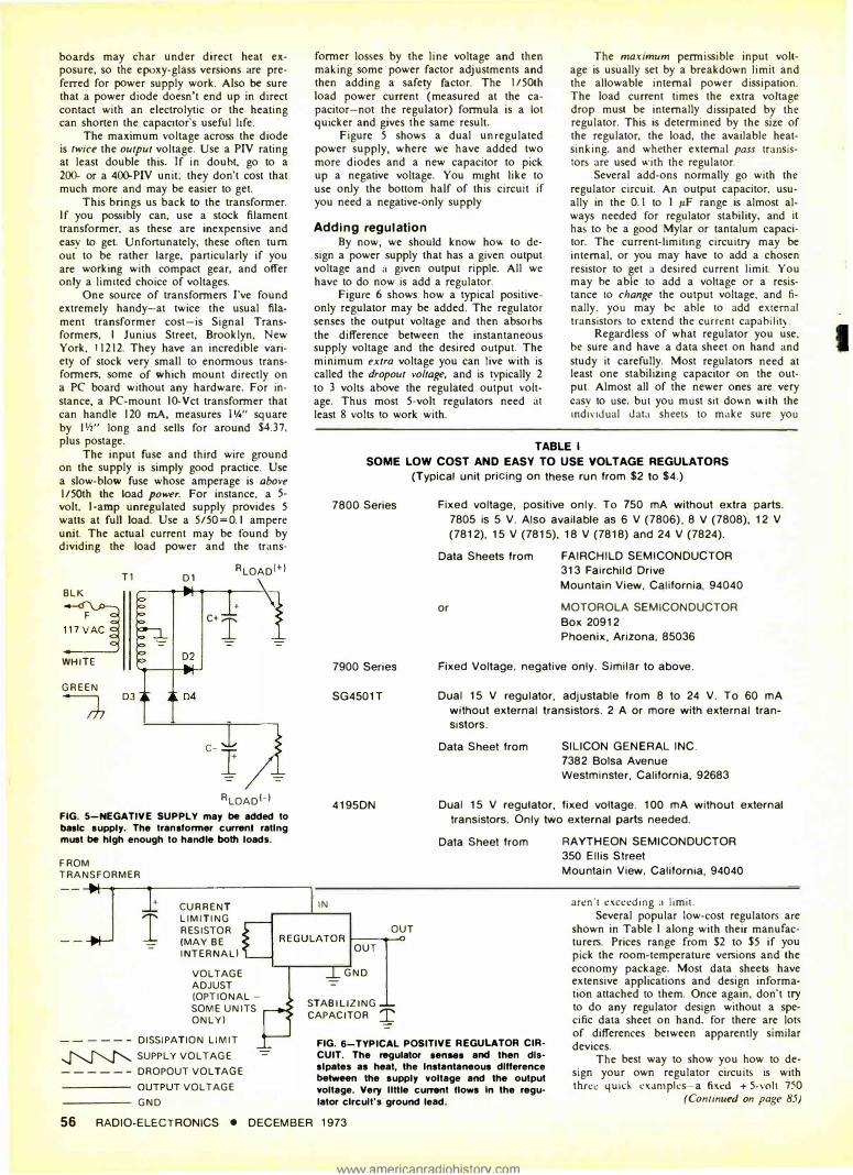
Figure 5 shows a dual unregulated power supply, where we have added two more diodes and a new capacitor to pick up a negative voltage. You might like to use only the bottom half of this circuit if you need a negative-only supply
Adding regulation By now, we should know how to de
sign a power supply that has a given output voltage and a given output ripple. All we have to do now is add a regulator.
Figure 6 shows how a typical positiveonly regulator may be added. The regulator senses the output voltage and then absorbs the difference between the instantaneous supply voltage and the desired output. The minimum extra voltage you can live with is called the dropout voltage, and is typically 2 to 3 volts above the regulated output voltage. Thus most 5-volt regulators need ar least 8 volts to work with.
The maximum permissible input voltage is usually set by a breakdown limit and the allowable internal power dissipation. The load current times the extra voltage drop must be internally dissipated by the regulator. This is determined by the size of the regulator, the load, the available heatsinking. and whether external pass transistors are used v.·ith the regulator.
Several add-ons normally go with the regulator circuit. An output capacitor. usually in the 0. I to I µ.F range is almost always needed for regulator stability. and it has to be a good Mylar or tantalum capacitor. The current-limiting circuitry may be internal, or you may have to add a chosen resistor to get a desired current limit. You may be able to add a voltage or a resistance to change the output voltage. and finally. you may be able 10 add external transistors to extend the current capability
Regardless of what regulator you use. be sure and have a data sheet on hand and study it carefully. Most regulators need at least one stabilizing capacitor on the output. Almost all of the newer ones are very easy to use. but you must sit down with the individual dat;1 sheets to make sure you
TABLE l
IN
SOME LOW COST AND EASY TO USE VOLTAGE REGULATORS
(Typical unit pricing on these run from $2 to $4.)
7800 Series
7900 Series
SG4501T
4195DN
OUT
Fixed. voltage, positive only. To 750 mA without extra parts.
7805 is 5 V. Also available as 6 V (7806), 8 V (7808), 12 V
(7812). 15 V (7815), 18 V (7818) and 24 V (7824).
Data Sheets from
or
FAIRCHILD SEMICONDUCTOR 313 Fairchild Drive
Mountain View. California, 94040
MOTOROLA SEMICONDUCTOR
Box 20912 Phoenix, Arizona, 85036
Fixed Voltage, negative only. Similar to above.
Dual 15 V regulator, adjustable from 8 to 24 V. To 60 mA
without external transistors. 2 A or more with external transistors.
Data Sheet from SILICON GENERAL INC.
7382 Balsa Avenue
Westminster, California, 92683
Dual 15 V regulator, fixed voltage. 100 mA without external
transistors. Only two external parts needed.
Data Sheet from RAYTHEON SEMICONDUCTOR 350 Ellis S treet
Mountain View, California, 94040
arcn "t exceeding a limit.
I CURRENT LIMITING RESISTOR (MAY BE INTERNAL)
REGULATOR ,__ ___ _,_,
Several popular low-cost regulators are shown in Table I along with their manufacturers. Prices range from $2 to $5 if you pick the room-temperature versions and the economy package. Most data sheets have extensive applications and design information attached to them. Once again. don't try to do any regulator design without a specific data sheet on hand, for there are lots of differences between apparently similar devices.
-=
VOLTAGE ADJUST (OPTIONAL -SOME UNITS ONLY)
DISSIPATION LIMIT � SUPPLY VOLTAGE ------DROPOUT VOLTAGE
----- OUTPUT VOLTAGE ----� GND
-=
OUT
GND
STABILIZING CAPACITOR T
FIG. 6'-TYPICAL POSITIVE REGULATOR CIRCUIT. The regulator 1enae1 and then dissipates as heat, the Instantaneous difference between the supply voltage and the output voltage. Very llttle cum1nt !lows In the regulator circuit's ground lead.
56 RADIO-ELECTRONICS • DECEMBER 1973
www ::imP.rir.::mrndiohistorv.com
The best way to show you how to design your own regulator circuits is with three 4uid cxampks-a fi�cd + 5-vc'lt 750
(Continued on page 85)
I
REGULATED POWER SUPPLIES (co111i1111eJ fro111 page 56)
mA logic supply. a dual plus-minus IS-volt. 1 00-mA op-amp supply, and finally a dual. variable, I-amp supply you can use for general lab use. If these basic circuits can't be used directly. you should be able to adapt them to fit your custom needs pretty well.
The 5-volt, 570 mA logic supply: We'll
Tl 16 VCT 640mA
SIGNAL PC-16-640
BLK .15 AMP
�� .
60- ::g WHT
+ 2500
I µF/150
-=-r - - IN
.. IN4002 HEATSINK I 7805 GRN
I I
the maximum permissible voltage across the regulator is S/0.7S =6.7 volts. For this circuit. the permissible range of supply voltage is then 7 to 11.7 volts. Let's aim for a 10-volt supply with 2-volts worth of ripple. splitting the difference on both ends.
First.. our capacitor size. An 8000-flF and I amp would give I volt of ripple. Similarly. reducing capacitance and current by onc-yuarter would still give I volt of ripple. or 6000 µF for 7SO mA. Halve the 6000 µF for double the ripple. or 3000 µF
FIG. 7-LOGIC CIRCUITS often require a regulated supply like this that delivers 5 volts at 750 mA. The 7805 needs a good heatsink. The transformer and other parts can be mounted on a PC board. See text reference to PC boards and heat dissipation.
OUT OUT
+ ·5V 75A
L - - GND I'
WHT
GRN
�
FRONT VIEW
7805 1000µ�
IN4004 + -=-
-=-
+ 1µF/6V � TANTALUM
FIG. 8-,(below) DUAL REGULATED SUPPL V uses the Raytheon 4195 series regulator. The ON type is OK if you keep current drain well below 100 mA. Use a more rugged regulator if the current is heavy.
L. NC NC p 3 +lOµF
+15V
2 lOOmA 4195DN MAX
-=- 4 5
15V
lOµF
Tl 28VCT.2A SIGNAL 56-.1
T +1000µF r- _r
FROM TRANSFORMER
+
I CURRENT LIMITING RESISTOR (MAY BE INTERNAL)
VOLTAGE ADJUST (OPTIONAL -
SOME UNITS ONLY)
- - - - --DISSIPATION LIMIT
�� SUPPLY VOLTAGE
------DROPOUT VOLTAGE
----- OUTPUT VOLTAGE
----- GND
-=-
IN
OUT REGULATOR 1-----0
OUT
GND
STABILIZING CAPACITOR T
-=- -=-
FIG. 9-DUAL 1-AMP SUPPLY has adjustable output voltage. The two transistors handle the load currents; series resistors determine the current limits. See text for details.
for 2 volts of ripple. We can probably cheal jusl a bit and get by wilh a 2SOO-µF. IS-volt electrolytic.
40 MHz DIGITAL FREQUENCY COUNTER:
• Will not be damaged by high power transmission levels.
• Simple, 1 cable connection to transmitter's output.
ES 220K - Line frequency time base. I KHz resolution. 5 digit: $69.50 Case extra: $10
ES 221K - Crystal time base. JOO Hz resolution. 6 digit $109.50 Case extra: $10.00
DIGITAL CLOCK:
. -
. I 2 2 8 c' I
ES I 12K/ 124K • 12 hr. or 24 hr. clock $46.95 Case extra, Walnut $12.00 • Metal $7 .50
CRYSTAL TIME BASE: ES 201K-Optional addition to ES 112K, 124K or SOOK. Mounts on board_ Accurate to. 002%.
I D REMINDER: ES 200K Reminds operator 9 min. 45 sec. have passed. Mounts on ES 112 or 124 board. Silent LED flash $9.95. Optional audio alarm $3.00 extra.
Dependable solid state components and circuitry.
Easy reading, 7 segment displa� tubes with clear, bright numerals. These products operate from 117 VAC, 60 cycles No moving parts. Quiel. trouble free
printed circuit.
Each kit contains compl-.te parts list with all parts, schematic illustrations and easy to follow, step by step instructions. No special tools required.
@ CRDER YOURS TODAY: Use your Mastercharge or Bankamericard l';loney Back Guarantee
10418 La C1enegai •Inglewood Ca 90304
(213" 674-3021
use the fixed 780S positive regulator for this. It internally current limits at 7SO mA and should be just what we need for a TTL or DTL system power supply. The dropout voltage is 2 volts. The maximum power· dissipation at room temperature with a good heatsink is slightly over S watts. This means
Outpul voltage at the capacitor. in absence of ripple, should be IO volts. Add a volt for the diode to get 11 volts. Multiply
(co111in11ed 011 !'"!!." 86) Circle 16 011 H!ada service card
DECEMBER 1973 • RADIO-ELECTRONICS 85
IMMN ::imP.rir.;:mr;:irtiohistorv r.om
ree 1974
�® CATALOG
NEWES'T SAVE on t�: tacnous· and 9£S'T �uct nnes • •
name pro
A superstore of electronics at your fingertips
• Stereo I 4-Channel Sound Systems • Tape Recorders and Accessories • Radios • Phonos • Kits • Amateur and Shortwave Gear • Citizens Band • Antennas • Police/Fire VHF-UHF Radios • Electronic Calculators and Timepieces • Security • Test Equipment • 1000's of Parts, Tubes, Batteries, Wire, Hardware
Exclusive TELEDYNE and OLSON Audio Products
'-'I�"" .. �u�\\te
1or the electronics in
FREE
1974 Catalog Send coupon
today
the VALUE leader since 1931
-------------, G>lson electronics Dept. LO I 260 S. Forge St.. Akron. Ohio 44327 I D Send me my FREE 1974 Olson I
Catalog (Please Print) I Name __ _ Apt.
Street __
I I I
City ____ State - Zip -- I D Send an Olson Cat!llog to my friend
I Name Apt. - I Street-- I \ City State __ Zip_ -- I
, ____________ , Circle 27 011 reader serl'ice card
REGULATED POWER SUPPLIES
(continued from page 85)
by 0.707 and get 8 volts. Double this for a 16-volt center tapped transformer. We need a 16-V ct transformer at 750 mA. Let's cheat again just a bit and use a 64�mA transformer, the Signal PC16-640. Jl/,X P/sX2", PC mount, and costing around $4.88, plus postage.
Figure 7 shows the circuit. A high quality 1-µF, 6-volt tantalum is used on the output for stability. The output power measured at the capacitor at maximum load is. 10 volts X.750 ampere=7.5 watts. The fuse should be 7.5/50 amp=0.15 ampere. Load current limiting is automatic and internal. Any reasonable-sized standing-up type of heatsink can be used, or the regulator may be bolted to the case (be sure to insulate it'}.
If we wanted a negative supply instead, there's several things we could do. If we only want a negative supply, simply call the + 5 line "ground" and the common line "-5". Note that if we do this, we don't use the transformer winding for any other voltages. positive or negative.
Another alternative is to turn the whole circuit upside down and use a negative regulator. Devices such as the 78N05 or the 7905 have been announced and should be readily available by the time you need them.
Dual 15-volt, 100-mA op-amp supply: Would you believe only three parts? This time we use the Raytheon 4195, in the lowcost DN minidip plastic package if we aren't going to be using things at the 100-
:iargthinq: Y.titf '¥lantetl Jo · knovi·ahoµt CD Ignition: ·
Send for FREE Tiger booklet (20 pages) which answers all your <1uestions.
Nan1e ___ _ _
Address. - ·--
City_. __ _
State __ -�--- Zip_
Cl.II' OCT !'HIS AD A!'-:D SE:--!D 1'0-
TRI-STAR CORP. P. 0. Box 1727 Dept. H Grand Junction, Colo. 81501
86 RADIO-ELECTRONICS • DECEMBER Circle 28 011 reader service card
1973
www.americanradiohistorv.com
mA end too much, or in the more expensive and more powerful T or TK packages if we are.
The dropout voltage is 3 volts: the dissipation limit is 6 (with the minidip}. Let's work on a 4-5 volt differential range as an input. One volt of ripple with 100 mA takes 800 µF. Let's use !000. The input voltage has to be 20 volts ( 15 + 5}. Add a volt for the diode to 21 volts. Multiply by 0.707 for rms to get 14.5. Double this for 29Vct Use a 28-volt transformer. The Signal 56-0.1 does the job with both secondaries in parallel. Two inches square by 1 W' ($4.66 plus postage}. Chassis mount this time.
This particular regulator takes larger, quality output capacitors; I0-11F tantalums are recommended. The final circuit is shown in Fig. 8. Input taps on the 56-1 transformer let you trim for optimum voltage range for your particular line voltage.
Variable 8-15-volt, I-amp bench supply: This circuit is shown in Fig. 9. We add two pass transistors to a SG4501 regulator and properly heatsink them. About 5000 microfarads should do, and the transformer can be a I amp (one per side} such as the Signal 56-1. Voltage is adjusted with the potentiometer shown. You can set the current limit by changing the two 0.6-ohm series resistors. Doubling the value to 1.2 ohms gives you a 500 mA limit; 2.4 ohms a 250 mA limit and so on.
With these basic circuits as guidelines, you should be able to build up most any low-voltage regulator circuit you want. Always remember to work directly with a data sheet, provide the needed stabilizing and outboard components, and keep the input voltage to the regulator above the dropout voltage and helow a value that causes excessive internal dissipation at high load currents.-Don Lancaster R-E
' James Brolin says:
"Birth defects are forever ... unless
you help!' Give to the
March of Dimes THIS SPACE CONTRIBUTED BY THE PUBL SHER