Page 1
1 11/18/05 JS Copyright © 2005 Ortronics/Legrand. All rights reserved.
Designing a Fiber Structured Cabling System for the Data Center
John M. Struhar, DirectorFiber SCS SolutionsOrtronics/Legrand
[email protected]
A Web Conference Presented by theTIA Fiber Optics LAN Section
Page 2
2 11/18/05 JS Copyright © 2005 Ortronics/Legrand. All rights reserved.
TIA Fiber Optics LAN Section (FOLS)
Founded in 1993 as a Section of the TIA’s Fiber Optics Division Mission: Educate system designers, architects, consultants, engineers, contractors, end users & the media about the technical advantages that optical transmission brings to customer-owned networks Stimulates development of new fiber standards and promotes optical-based applications in customer-owned networks
Page 3
3 11/18/05 JS Copyright © 2005 Ortronics/Legrand. All rights reserved.
Introduction to new standards-based data center & storage area network designSelecting the optimal fiber structured cabling system for your data center & storage area network
Today’s AgendaDesigning a Fiber SCS for the Data Center
Page 4
4 11/18/05 JS Copyright © 2005 Ortronics/Legrand. All rights reserved.
Introduction to new standards-based data center & storage area network design– Information generation & storage trends
– Data center & storage area network growth
– Introduction to the new TIA-942 data center standard
Page 5
5 11/18/05 JS Copyright © 2005 Ortronics/Legrand. All rights reserved.
2002 new information production: 5 exabytes– 1 exabyte – 1,000,000,000,000,000,000 bytes– New digital information = 1 Library of Congress every 15 minutes
Four primary physical media– Print– Film– Magnetic– Optical
350% more information communicated than stored (2002: 18 exabytes)Four electronic channels
– Telephone– Radio– Television– Internet
Source: “How Much Information 2003?”, School of Information Management & Systems at University of California at Berkeley
New information doubled in last 3 years
New Information GenerationSignificant Annual Increases
Page 6
11/18/05 JS Copyright © 2005 Ortronics/Legrand. All rights reserved.
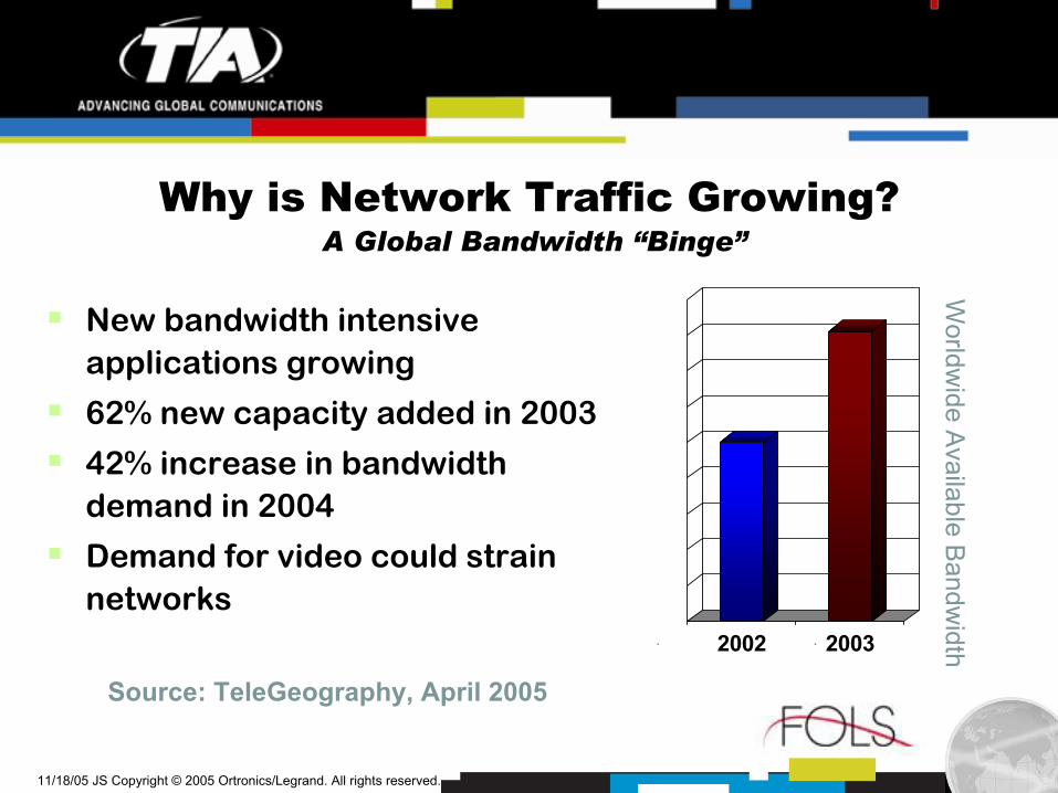
Why is Network Traffic Growing?A Global Bandwidth “Binge”
New bandwidth intensive applications growing
62% new capacity added in 2003
42% increase in bandwidth demand in 2004
Demand for video could strain networks
Source: TeleGeography, April 2005
2002 2003
Worldw
ide Available B
andwidth
Page 7
7 11/18/05 JS Copyright © 2005 Ortronics/Legrand. All rights reserved.
Why Are Data Center & SANs Growing?U.S. Legislation & Recommendations
Sarbanes-Oxley Act
Health Insurance Portability & Accountability Act (HIPAA)
Graham-Leach-Bliley Financial Services Modernization Act
U.S Federal Reserve
Securities & Exchange Commission – Rule 17a
SB 1386 - California
Page 8
8 11/18/05 JS Copyright © 2005 Ortronics/Legrand. All rights reserved.
Introduction to new standards-based data center & storage area network design– Information generation & storage trends
– Data center & storage area network growth
– Introduction to the new TIA-942 data center standard
Page 9
9 11/18/05 JS Copyright © 2005 Ortronics/Legrand. All rights reserved.
DefinitionsData Center & Storage Area Network
Data Center
– “The factory floor of the information age”
– ISP: Specialized facility that houses web sites & provides data serving & other services for other companies
– Enterprise: Central data processing facility and/or the group of people who manage the enterprise’s data processing & networks
Storage Area Network (SAN)
– High-speed special purpose network (or subnetwork) that interconnects different kinds of data storage devices with associated data servers on behalf of a larger network of users
– Usually located in Data Center
Source: http://www.whatis.com
Page 10
10 11/18/05 JS Copyright © 2005 Ortronics/Legrand. All rights reserved.
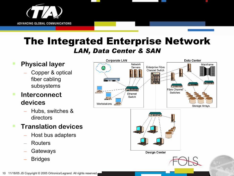
The Integrated Enterprise NetworkLAN, Data Center & SAN
Physical layer– Copper & optical
fiber cabling subsystems
Interconnect devices
– Hubs, switches & directors
Translation devices– Host bus adapters– Routers– Gateways– Bridges
Page 11
11/18/05 JS Copyright © 2005 Ortronics/Legrand. All rights reserved.
Data Center GrowthRapid & Significant
Large enterprise 50% yearly data growth
Undergoing major technological shifts
$7.4 billion market by 2009
Sources: Yankee Group & IDC reports, 2004 & 2005
Page 12
11/18/05 JS Copyright © 2005 Ortronics/Legrand. All rights reserved.
Networked Storage GrowthOutpaces Overall Storage Market Growth
Network Attached Storage (NAS) & Storage Area Networks (SANs)
– 2004: 50% of overall storage market
– 12% CAGR vs. 5%
– 2005: 38% Fibre Channel port shipment growth
Dollars invested
– 18% of total I.T. budget
– 60% of hardware budget
Source: Dell ‘Oro Group 2005, iSuppli Corporation, 2004
0.0
20.0
40.0
60.0
80.0
100.0
120.0
140.0
2004 2005
Fibre Channel Port Shipments
Page 13
13 11/18/05 JS Copyright © 2005 Ortronics/Legrand. All rights reserved.
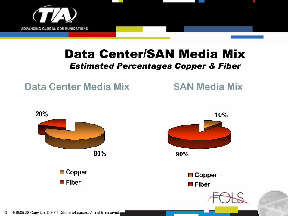
Data Center/SAN Media MixEstimated Percentages Copper & Fiber
80%
20%
CopperFiber
Data Center Media Mix
10%
90%
CopperFiber
SAN Media Mix
Page 14
14 11/18/05 JS Copyright © 2005 Ortronics/Legrand. All rights reserved.
Fibre Channel Technology in SANsShort Wavelength VCSELs the Dominant Device
0
5,000
10,000
15,000
20,000
2001 2002 2003 2004 2005 2006 2007 2008
8 Gbps4 Gbps2 Gbps1 Gbps
Source: High Speed Optical Data Link Modules,Market Review & Forecast, Strategies Unlimited, 2002
Fibre Channel Units in Thousands
Page 15
15 11/18/05 JS Copyright © 2005 Ortronics/Legrand. All rights reserved.
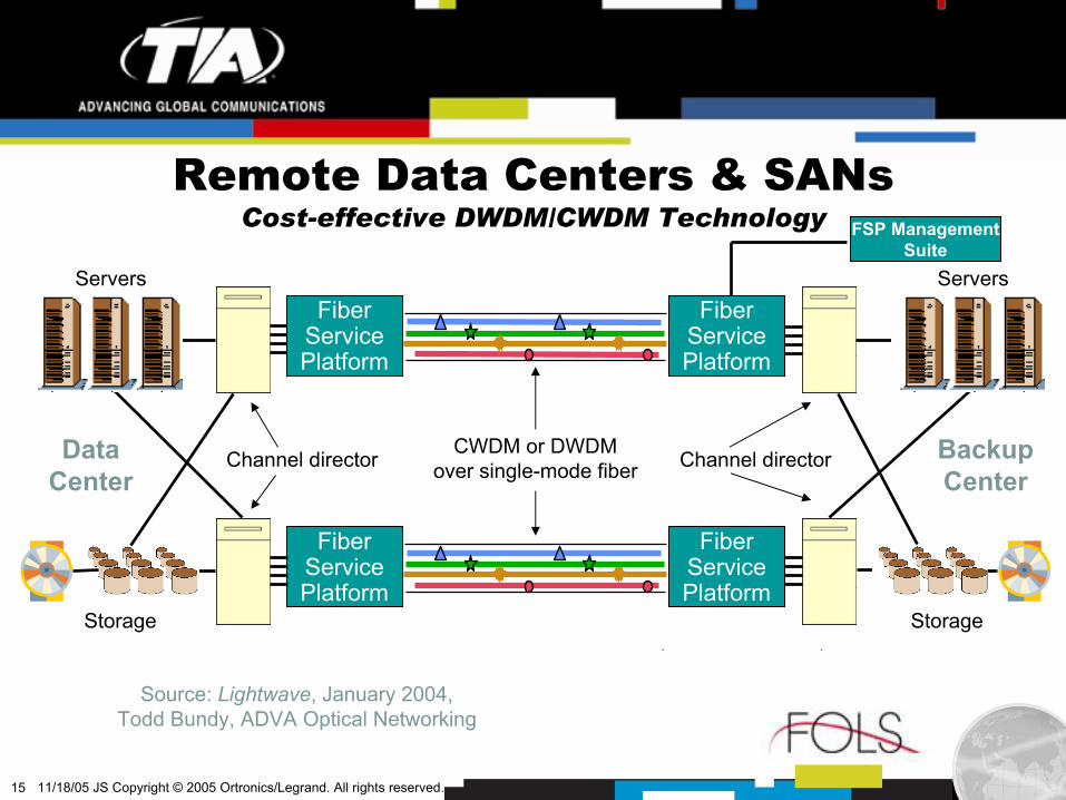
FiberServicePlatform
FiberServicePlatform
FiberServicePlatform
FiberServicePlatform
FSP ManagementSuite
CWDM or DWDMover single-mode fiberChannel director Channel directorData
Center
Servers
Storage
BackupCenter
Servers
Storage
Source: Lightwave, January 2004,Todd Bundy, ADVA Optical Networking
Remote Data Centers & SANsCost-effective DWDM/CWDM Technology
Page 16
16 11/18/05 JS Copyright © 2005 Ortronics/Legrand. All rights reserved.
Data Center Upgrade ExampleFor 50% Annual Storage Capacity Growth
10,000 ft2 data center
50% annual capacity increase typical
Doubling of floor space required every 3-5 years
Data center floor space cost: $700-1200/ft2
Upgrade cost: $8-12 million over 3 year period
Source: The Meta Group, “Room at the Data Center?” 8-01
Page 17
17 11/18/05 JS Copyright © 2005 Ortronics/Legrand. All rights reserved.
Insufficient DC/SAN Infrastructure InvestmentThe Costs are Staggering
Ramifications– Minimized customer transactions, interactions
& sales volumes– Decreased revenues
Network downtime estimates:– Pay-per-view TV operator: $125,000 per hour– Credit card authorization company:
$2,600,000 per hour– Retail brokerage: $6,400,000 per hour
Source: Lightwave, January 2004Todd Bundy, ADVA Optical Networking
Page 18
18 11/18/05 JS Copyright © 2005 Ortronics/Legrand. All rights reserved.
Introduction to new standards-based data center & storage area network design– Information generation & storage trends
– Data center & storage area network growth
– Introduction to the new TIA-942 data center standard
Page 19
19 11/18/05 JS Copyright © 2005 Ortronics/Legrand. All rights reserved.
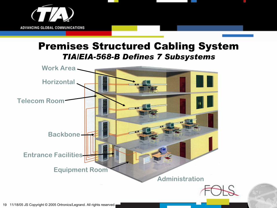
Work Area
Horizontal
Telecom Room
Backbone
Entrance Facilities
Equipment RoomAdministration
Premises Structured Cabling SystemTIA/EIA-568-B Defines 7 Subsystems
Page 20
20 11/18/05 JS Copyright © 2005 Ortronics/Legrand. All rights reserved.
Do We Really Need Another Standard?Don’t We Already Have Too Many?
Page 21
21 11/18/05 JS Copyright © 2005 Ortronics/Legrand. All rights reserved.
Data Center Cabling StandardsStructured Cabling Systems for the Data Centers & SANs
TIA-942– “Telecommunications Infrastructure Standard for Data Centers”– Published: April 2005– Order from Global Engineering Documents (www.global.ihs.com)
CENELEC– EN 50173-5
• “Information technology - Generic cabling systems – Part 5: Data Centres”• Expected publication: Early 2006
– EN 50174-2 Amendment• Adds Annex on Data Center planning & installation
ISO/IEC– “Generic Cabling for Data Centres – Proposed”– ISO/IEC JTC-1/SC 25/WG 3
Page 22
22 11/18/05 JS Copyright © 2005 Ortronics/Legrand. All rights reserved.
TIA-942 Data Center StandardObjective
Requirements & guidelines for the design & installation of a data center or computer room
Intended for use by designers needing thorough understanding of data center design
Comprehensive document
Access
RedundancyElectrical designLocation
Water intrusionEnvironmental designNetwork Design
Fire protectionArchitectural designCabling
Page 23
23 11/18/05 JS Copyright © 2005 Ortronics/Legrand. All rights reserved.
Data Center Structured Cabling System9 Elements Comprise TIA-942
1. Computer room
2. Telecommunications room
3. Entrance room
4. Main distribution area
5. Horizontal distribution area
6. Zone distribution area
7. Equipment distribution area
8. Backbone cabling
9. Horizontal cabling
Spaces
Cabling subsystems
Page 24
24 11/18/05 JS Copyright © 2005 Ortronics/Legrand. All rights reserved.
Data Center CablingFor the Backbone & Horizontal Cabling Subsystems
Backbone subsystem (fiber)– Backbone cables– Main cross-connects– Horizontal cross-connects– Mechanical terminations– Patch cords
Horizontal subsystem (fiber or copper)
– Horizontal cables– Mechanical terminations– Patch cords– Zone outlet or consolidation point (optional)
Page 25
25 11/18/05 JS Copyright © 2005 Ortronics/Legrand. All rights reserved.
TIA-942 Data Center StandardSupported Architectures
Basic data center topology
Distributed data center topology
Reduced data center topology
Centralized fiber optic cabling topology
Page 26
26 11/18/05 JS Copyright © 2005 Ortronics/Legrand. All rights reserved.
Basic Data Center TopologyAnd TIA/EIA-568-B Counterparts
Entrance Room– Analogy: “Entrance Facility”
Main Distribution Area (MDA)– Analogy: “Equipment Room”
Horizontal Distribution Area (HDA)
– Analogy: “Telecom Room”Zone Distribution Area (ZDA)
– Analogy: “Consolidation Point”Equipment Distribution Area (EDA)
– Analogy: “Work Area”
Page 27
27 11/18/05 JS Copyright © 2005 Ortronics/Legrand. All rights reserved.
Distributed Data Center TopologyWith Multiple Entrance Rooms
May be required for large data centers
Circuit distance limitations may require multiple entrance rooms
Primary entrance room has no direct connections to HDASecondary entrance room may be directly connected to HDA conditionally
Page 28
28 11/18/05 JS Copyright © 2005 Ortronics/Legrand. All rights reserved.
Reduced Data Center TopologyFor Many Enterprise Installations
HDA combined with MDA
Telecom room can also be consolidated into MDA
Copper or fiber in the horizontal
Page 29
29 11/18/05 JS Copyright © 2005 Ortronics/Legrand. All rights reserved.
Data Center Centralized Fiber CablingSignificant Cost Savings Possible
Alternative to optical cross-connection in the horizontal distribution areaNo electronics in horizontal distribution area (HDA) Centralized electronicsCost reduction factors
– Smaller, simpler HDA– Faster & easier installation &
testing– Fewer idle ports– Centralized administration– Simplified moves, adds &
changesVisit TIA Fiber Optics LAN Section web site forinformation on centralized fiber cabling: www.fols.org
Page 30
30 11/18/05 JS Copyright © 2005 Ortronics/Legrand. All rights reserved.
TIA/EIA-942 (2005) EN 50173-5 (2006)
ZD
ZD
MD
ENI
EO
EO
LDP
ENI
EO
EO
EO
EO
Main
Distribution A
rea
Entrance Room
Horizontal
Distribution A
rea
EquipmentDistribution
Area
ZoneD
istributionA
rea
TIA-942 & Draft EN 50173-5 ComparedSimilarities & Differences
Courtesy: Mike Gilmore, e-Ready Building Limited (2004)
Equipment Outlet (EO)Connection point within the EDA
Local Distribution Point (LDP)Connection point within the ZDA
Zone Distributor (ZD)Functional distribution element within the HDA
Main Distributor (MD)Functional distribution element within the MDA
Equipment Network Interface (ENI)Connection point to the outside world
Page 31
31 11/18/05 JS Copyright © 2005 Ortronics/Legrand. All rights reserved.
Media SelectionDesign Considerations per TIA-942
Flexibility with respect to supported services
Required useful life of cabling
Facility site/size & occupant population
Channel capacity within the cabling system
Equipment vendor recommendations or specifications
Same facility architecture if different media types used
Page 32
32 11/18/05 JS Copyright © 2005 Ortronics/Legrand. All rights reserved.
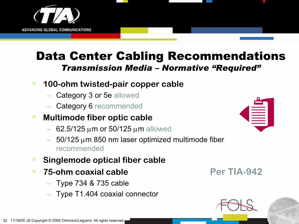
Data Center Cabling RecommendationsTransmission Media – Normative “Required”
100-ohm twisted-pair copper cable– Category 3 or 5e allowed– Category 6 recommended
Multimode fiber optic cable– 62.5/125 µm or 50/125 µm allowed– 50/125 µm 850 nm laser optimized multimode fiber
recommendedSinglemode optical fiber cable75-ohm coaxial cable– Type 734 & 735 cable– Type T1.404 coaxial connector
Per TIA-942
Page 33
33 11/18/05 JS Copyright © 2005 Ortronics/Legrand. All rights reserved.
Data Center CablingDesign Recommendations (Informative) - “Optional”
Copper design (informative)– Adequate spacing for labeling on each patch panel– Label each port per Annex B and ANSI/TIA/EIA-606-A
Fiber design (informative)– Installation time reductions– Multi-fiber increments & multi-fiber connectors– Pre-calculated, pre-terminated multi-fiber ribbon assemblies– Consider performance effects of additional connections
Per TIA-942
Page 34
34 11/18/05 JS Copyright © 2005 Ortronics/Legrand. All rights reserved.
Data Center StandardMultiple Benefits to Designers & Managers
Consistency in design
Predictable level of performance
More choice in the marketplace
Interoperability between different vendors’ products
Economies of scale
Page 35
35 11/18/05 JS Copyright © 2005 Ortronics/Legrand. All rights reserved.
Introduction to new standards-based data center & storage area network designSelecting the optimal fiber structured cabling system for your data center & storage area network
Page 36
36 11/18/05 JS Copyright © 2005 Ortronics/Legrand. All rights reserved.
Why is the choice of a fiber structured cabling system so
important in data centers & SANs?
Guidelines for selecting the fiber termination methodGuidelines for selecting the fiber termination method
Connecting the system elements togetherConnecting the system elements together
AgendaSelecting the Optimal Fiber SCS for your Data Center & SAN
Page 37
37 11/18/05 JS Copyright © 2005 Ortronics/Legrand. All rights reserved.
Higher Speed Networks More DemandingFiber, Cable & Connectivity Choices Critical
– Fiber cable plant loss budgets continue to decrease
– Widely perceived 2.6 dB budget for 10 Gbps Ethernet & Fibre Channel
– Installation techniques more challenging
– Advanced fiber SCS technology provides new options
Page 38
38 11/18/05 JS Copyright © 2005 Ortronics/Legrand. All rights reserved.
OFL = Overfilled launchEMB = Effective modal (laser) bandwidth
OM1, OM2, OM3 designationsPer ISO/IEC 11801, 2nd Edition
Min Bandwidth
(MHz km)
Fiber type
Wavelength
(nm)
Max Loss (dB/km) OFL EMB
1 Gb/s Reach (meters)
10 Gb/s Reach (meters)
62.5 µm (OM1) 850 1300
3.5 1.5
200 500
n.s.* n.s.
275 550
33 300
50 µm (OM2) 850 1300
3.5 1.5
500 500
n.s. n.s.
550 550
82 300
850-nm 10G Laser-Optimized
50 µm (OM3)
850 1300
3.5 1.5
1500 500
2000 n.s.
1000 600
300 300
Multimode FibersIndustry Standard Types
*n.s. = Not specified
Page 39
39 11/18/05 JS Copyright © 2005 Ortronics/Legrand. All rights reserved.
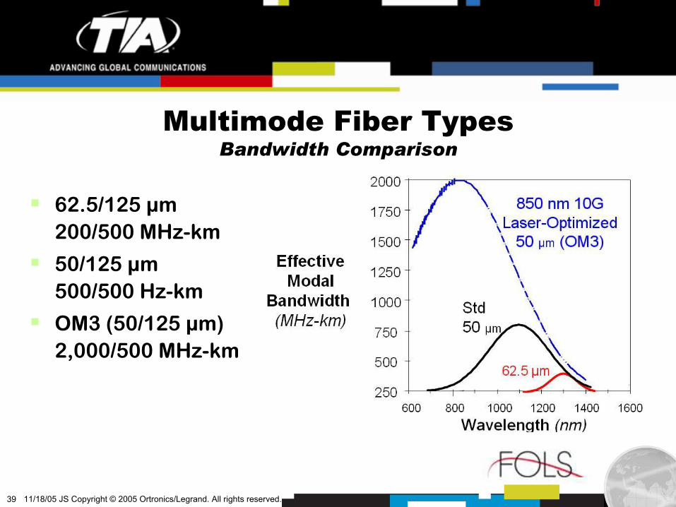
Multimode Fiber TypesBandwidth Comparison
62.5/125 µm200/500 MHz-km
50/125 µm500/500 Hz-km
OM3 (50/125 µm)2,000/500 MHz-km
Page 40
40 11/18/05 JS Copyright © 2005 Ortronics/Legrand. All rights reserved.
Ethernet Fiber Loss Budgets DecreasingDue to Ever Increasing Speeds
2.60IEEE 802.3ae10GBASE-SR*10,000 Mbps10 Gigabit Ethernet2004
3.56IEEE 802.3z1000BASE-SX1,000 Mbps1 Gigabit Ethernet2000
4.0TIA/EIA-785100BASE-SX10/100 MbpsShort Wavelength Fast Ethernet
Late 90’s
11.0IEEE 802.3100BASE-FX100 MbpsFast EthernetEarly 90’s
12.5IEEE 802.310BASE-FL10 MbpsEthernetEarly 80’s
Cable Plant Loss Budget
(db)
StandardDesignationData RateApplicationYear
Insertion loss values are for maximum distance specified in the standard& can vary based on the distance & number of connections
Page 41
41 11/18/05 JS Copyright © 2005 Ortronics/Legrand. All rights reserved.
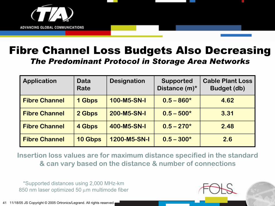
Fibre Channel Loss Budgets Also DecreasingThe Predominant Protocol in Storage Area Networks
2.60.5 – 300*1200-M5-SN-I10 GbpsFibre Channel
2.480.5 – 270*400-M5-SN-I4 GbpsFibre Channel
3.310.5 – 500*200-M5-SN-I2 GbpsFibre Channel
4.620.5 – 860*100-M5-SN-I1 GbpsFibre Channel
Cable Plant Loss Budget (db)
Supported Distance (m)*
DesignationData Rate
Application
*Supported distances using 2,000 MHz-km850 nm laser optimized 50 µm multimode fiber
Insertion loss values are for maximum distance specified in the standard& can vary based on the distance & number of connections
Page 42
42 11/18/05 JS Copyright © 2005 Ortronics/Legrand. All rights reserved.
Reliable, high bandwidth networks required
The optimal solution: systems engineered, manufactured & independently verified to meet & exceed worldwide standards requirements
Performance of individual fiber network elements critical1. Electronics: Fully qualified devices with high laser coupling efficiency2. Fiber: Low DMD or high EMBc
3. Cable: Low attenuation4. Apparatus: Reduced insertion loss per mated pair
Key Elements of a Robust DC/SANTo Support Multiple Generations of Electronics
Page 43
43 11/18/05 JS Copyright © 2005 Ortronics/Legrand. All rights reserved.
850 nm laserspot projected
on 50 µm fiber core
850 nm operating wavelength more cost effective
Small Form Factor Pluggable (SFP) modules dominant
Broad manufacturer availability
Fully qualified devices recommended
Ethernet & Fibre Channel TransceiversLook For High Laser Coupling Efficiency
Most power is inside9-38 µm “donut”
Page 44
44 11/18/05 JS Copyright © 2005 Ortronics/Legrand. All rights reserved.
Cables with low attenuation tested & verified not to degrade fiber performance in 10 Gbps networks
Tight control over buffer uniformity & concentricity for highest connector performance
Cable Design & ManufacturingCan Affect 10 Gbps Performance
Page 45
45 11/18/05 JS Copyright © 2005 Ortronics/Legrand. All rights reserved.
Small-Form-Factor Fiber ConnectorsHigh Density Critical for Space-Limited Data Centers
VF-45 OptiJack
MT-RJ LC
LX.5
Page 46
46 11/18/05 JS Copyright © 2005 Ortronics/Legrand. All rights reserved.
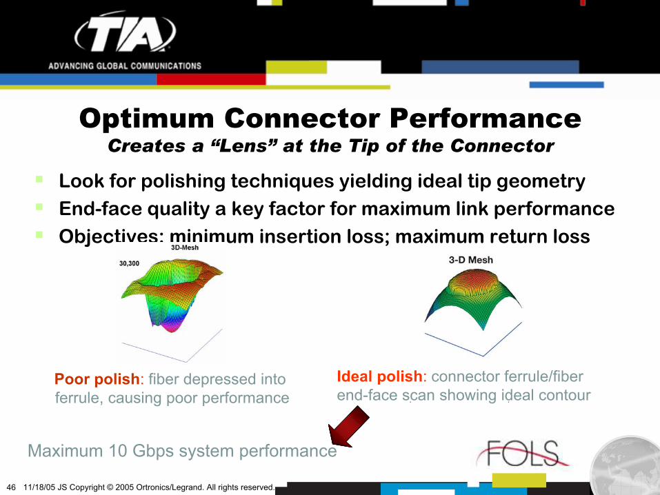
Look for polishing techniques yielding ideal tip geometryEnd-face quality a key factor for maximum link performanceObjectives: minimum insertion loss; maximum return loss
Ideal polish: connector ferrule/fiberend-face scan showing ideal contour
Poor polish: fiber depressed intoferrule, causing poor performance
Optimum Connector PerformanceCreates a “Lens” at the Tip of the Connector
Maximum 10 Gbps system performance
Page 47
47 11/18/05 JS Copyright © 2005 Ortronics/Legrand. All rights reserved.
Power budget consumed by various impairments
– Cross noise– Receiver eye opening– Relative intensity noise– Mode partition noise– Inter-symbol interference (ISI)– Channel insertion loss
Robust fibre solutions– Low insertion loss– Low Differential Mode Delay (DMD)– “Borrow” budget from other areas for
channel insertion loss
Cross noiseReceiver eye openingRelative intensity noise
Mode partition noise
Inter-symbol interference (ISI)
Channel insertion loss (ChIL)To
tal A
vaila
ble
Pow
er in
dB
10 Gbps Multimode Cabling SystemIEEE Link Model 850 nm Serial, 2,000 MHz-km MMF
75% of total penalty
Page 48
48 11/18/05 JS Copyright © 2005 Ortronics/Legrand. All rights reserved.
Reallocating ISI Loss PenaltyUsing State-of-the-Art Fiber Technology
Ideal application to MTP/MPO-based systems
Ideal for data centers & SANs
Exchange ISI for channel insertion loss
Page 49
49 11/18/05 JS Copyright © 2005 Ortronics/Legrand. All rights reserved.
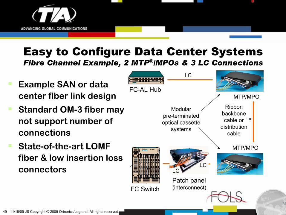
FC Switch
FC-AL Hub
LC
MTP/MPO
MTP/MPO
Patch panel(interconnect)
Ribbonbackbonecable or
distributioncable
Modularpre-terminatedoptical cassette
systems
LCLC
MT
Easy to Configure Data Center SystemsFibre Channel Example, 2 MTP®/MPOs & 3 LC Connections
Example SAN or data center fiber link design
Standard OM-3 fiber may not support number of connections
State-of-the-art LOMF fiber & low insertion loss connectors
Page 50
50 11/18/05 JS Copyright © 2005 Ortronics/Legrand. All rights reserved.
Why is the choice of a fiber structured cabling system so
important in data centers & SANs?
Guidelines for selecting the fiber termination method
Connecting the system elements together
AgendaSelecting the Optimal Fiber SCS for your Data Center & SAN
Page 51
51 11/18/05 JS Copyright © 2005 Ortronics/Legrand. All rights reserved.
Available Fiber Termination MethodsMultiple Solutions for Data Centers & SANs
MultimodeCassette-based Pre-terminatedField-terminated
Single-mode Cassette-basedPre-terminatedField-terminated
Page 52
52 11/18/05 JS Copyright © 2005 Ortronics/Legrand. All rights reserved.
Cassette-Based DC/SAN SolutionRibbon Backbone or Ribbonized Fiber Cable
Definition: Ribbon backbone or reduced diameter loose tube cable terminated with MTP/MPO connectors designed to interface with optical cassette system
Ideal for use in the Zone Distribution Area (ZDA)
Page 53
53 11/18/05 JS Copyright © 2005 Ortronics/Legrand. All rights reserved.
Cassette-Based DC/SAN SolutionSelection Criteria
Guaranteed optical performanceFactory terminated solution
Designed for interoperabilityIntegrated system
Integration with existing systemsDistributes optical signals to common LC & SC interfaces
Significant cost savingsEasy, fast, error-free installation
Standards-based systemCompliant with TIA SP-3-4424-AD7*
Greatly simplified connectivityCassette supports multiple fibers
Ideal for data centers & SANsHighly reliable
AdvantageDesign Element
*to become TIA/EIA-568-B.3, Addendum 7
Page 54
54 11/18/05 JS Copyright © 2005 Ortronics/Legrand. All rights reserved.
Pre-Terminated DC/SAN SolutionTime & Labor Saving Backbone Cable Designs
Definition: Backbone cable with factory installed connectors extending from rear of adapter panel to mating end of another adapter panel in another rack
Page 55
55 11/18/05 JS Copyright © 2005 Ortronics/Legrand. All rights reserved.
Pre-Terminated DC/SAN SolutionSelection Criteria
Guaranteed optical performanceFactory terminated solution
Solution for every applicationDistribution, armored, or reduced diameter plenum cable
Better air flow & less congestionSmaller overall cable diameter & cross-sectional areas
Reduced on-site time & labor costsFast & easy installation
Facilitates cable routing & dressingMultiple optical links contained in one sheath
AdvantageDesign Element
Page 56
56 11/18/05 JS Copyright © 2005 Ortronics/Legrand. All rights reserved.
Field-Terminated DC/SAN SolutionTime & Labor Saving Backbone Cable Designs
Definition: Field-installable fiber optic connectors installed on-site with local installation crews
LC
SC
Fiber connector field termination kit
Page 57
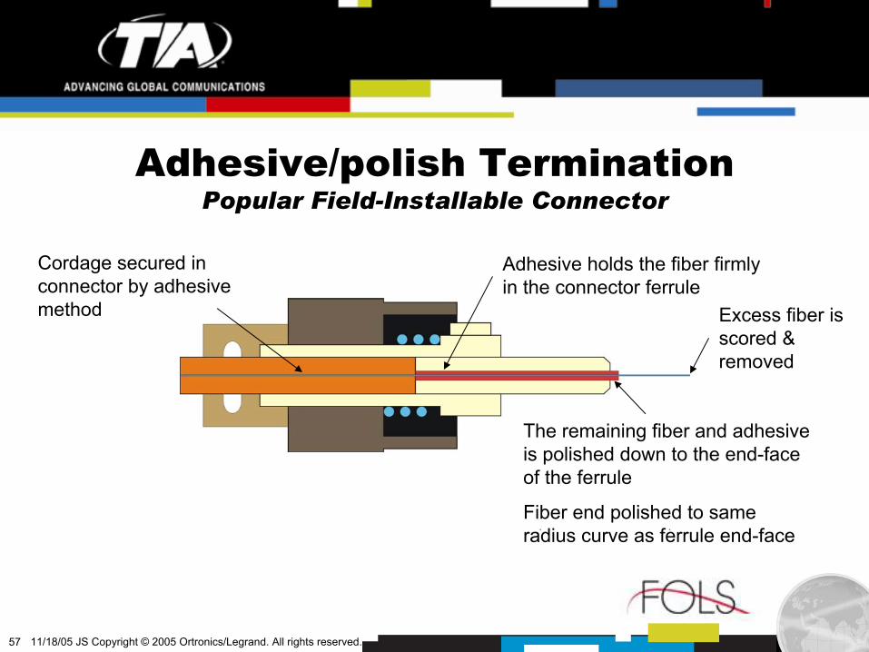
57 11/18/05 JS Copyright © 2005 Ortronics/Legrand. All rights reserved.
Adhesive holds the fiber firmly in the connector ferrule
Excess fiber is scored & removed
The remaining fiber and adhesive is polished down to the end-face of the ferrule
Fiber end polished to same radius curve as ferrule end-face
Cordage secured in connector by adhesive method
Adhesive/polish TerminationPopular Field-Installable Connector
Page 58
58 11/18/05 JS Copyright © 2005 Ortronics/Legrand. All rights reserved.
No-polish TerminationReduced On-Site Labor Costs
Fiber end polished and tested at the factory to same radius curve as ferrule end-face
Adhesive holds the factory-installed fiber stub firmly in the connector ferrule
Drop of index-matching gel providesoptical interface for cleaved fibers
Mechanical splice joins factory-installedfiber stub and fiber being terminated
Page 59
59 11/18/05 JS Copyright © 2005 Ortronics/Legrand. All rights reserved.
Field-Terminated DC/SAN SolutionSelection Criteria
Minimize hybrid patch cordsConnector choices may unique to specific data center/SAN
Reduced on-site labor costsNo polish connector requires less consumables
Fewer installation errorsLook for complete, easy to understand instructions
Good choice for skilled installersState-of-the-art fiber connector designs
Reduced on-site labor costsAnaerobic adhesive connector requires no heating oven
Integration with existing systemsWide range of popular connector types available
AdvantageDesign Element
Page 60
60 11/18/05 JS Copyright © 2005 Ortronics/Legrand. All rights reserved.
Why is the choice of a fiber structured cabling system so
important in data centers & SANs?
Guidelines for selecting the fiber termination method
Connecting the system elements together
AgendaStructured Cabling Systems in Data Centers & SANs
Page 61
61 11/18/05 JS Copyright © 2005 Ortronics/Legrand. All rights reserved.
Cassette-Based Data Center SolutionChannel Components for 10 Gbps Multimode System
Page 62
62 11/18/05 JS Copyright © 2005 Ortronics/Legrand. All rights reserved.
Pre-Terminated Data Center SolutionChannel Components for Single-mode System
Cable ManagementRack
Rack MountFiber Patch Cabinet Single Mode
Duplex Patch Cord
LC Adapter Panel24 Fiber
Cable ManagementRack
SC Adapter Panel12 Fiber
Single ModeDuplex Patch CordRack Mount
Fiber Patch Cabinet
Page 63
63 11/18/05 JS Copyright © 2005 Ortronics/Legrand. All rights reserved.
Field-Terminated Data Center SolutionChannel Components for 10 Gbps Multimode System
Cable ManagementRack
Rack MountFiber Patch Cabinet
Cable ManagementRack
LOMF FiberPatch Cord
LOMF FiberPatch Cord
Rack MountFiber Patch Cabinet
LC Adapter Panel24 Fiber
SC Adapter Panel12 Fiber
Page 64
64 11/18/05 JS Copyright © 2005 Ortronics/Legrand. All rights reserved.
SummaryData Centers & SANs: Rapidly Growing SCS Applications
Vast amounts of new information being created, communicated & stored
Legislation & other business priorities impacting data center & storage area network growth
The TIA-942 Data Center Standard applies structured cabling principles as TIA/EIA-568 did for commercial buildings
Careful choice of structured cabling system products should span multiple of generations of data center systems
Page 65
65 11/18/05 JS Copyright © 2005 Ortronics/Legrand. All rights reserved.
Designing a Fiber Structured Cabling System for the Data Center