66
ARCH Designing Cisco Network Service Architectures Version 2.0 Lab Guide 05.03.07
| Date post: | 23-Oct-2015 |
| Category: |
Documents |
| Upload: | lindsay-pierce |
| View: | 83 times |
| Download: | 2 times |
ARCH
Designing Cisco Network Service Architectures
Version 2.0
Lab Guide
05.03.07
ii Designing Cisco Network Service Architectures (ARCH) v2.0 © 2007 Cisco Systems, Inc.
DISCLAIMER WARRANTY: THIS CONTENT IS BEING PROVIDED “AS IS.” CISCO MAKES AND YOU RECEIVE NO WARRANTIES IN CONNECTION WITH THE CONTENT PROVIDED HEREUNDER, EXPRESS, IMPLIED, STATUTORY OR IN ANY OTHER PROVISION OF THIS CONTENT OR COMMUNICATION BETWEEN CISCO AND YOU. CISCO SPECIFICALLY DISCLAIMS ALL IMPLIED WARRANTIES, INCLUDING WARRANTIES OF MERCHANTABILITY, NON-INFRINGEMENT AND FITNESS FOR A PARTICULAR PURPOSE, OR ARISING FROM A COURSE OF DEALING, USAGE OR TRADE PRACTICE. This learning product may contain early release content, and while Cisco believes it to be accurate, it falls subject to the disclaimer above.
© 2007 Cisco Systems, Inc. Lab Guide iii
Table of Contents Lab Guide 1
Overview 1 Outline 1
Case Study 1: MegaCorp Campus Design 2 Activity Objective 2 Visual Objective 2 Required Resources 2 MegaCorp Campus Case Study Scenario 3 Campus Design: Business Factors 4 Campus Design: Technical Factors 5 MegaCorp Campus Design Tasks 6 Activity Verification 8
Case Study 2: CP Hotels Addressing and Routing Design 9 Activity Objective 9 Visual Objective 9 Required Resources 10 CP Hotels Case Study Scenario 10 CP Hotels Design Tasks 19 Activity Verification 20
Case Study 3: CP Hotels Network Initiatives 21 Activity Objective 21 Visual Objective 21 Required Resources 21 CP Hotels Case Study Scenario 22 CP Hotels Design Tasks 24 CP Hotels Design Tasks 24 Activity Verification 26
Case Study 4: CP Hotels Security and IPsec VPN Network 27 Activity Objective 27 Visual Objective 27 Required Resources 27 CP Hotels Case Study Scenario 27 CP Hotels Design Tasks 32 Activity Verification 33
Case Study 5: DS Medical Research Institute Network Infrastructure 35 Activity Objective 35 Visual Objective 35 Required Resources 36 DS-MRI Case Study Scenario 36 DS-MRI Design Tasks 37 Activity Verification 39
Answer Key 41 Case Study 1 Answer Key: MegaCorp Campus Design 41 Case Study 2 Answer Key: CP Hotels Addressing and Routing Design 45 Case Study 3 Answers: CP Hotels Network Initiatives 49 Case Study 4 Answer Key: CP Hotels Security and IPsec VPN Network 53 Case Study 5 Answer Key: DS Medical Research Institute Network Infrastructure 57

iv Designing Cisco Network Service Architectures (ARCH) v2.0 © 2007 Cisco Systems, Inc.
ARCH
Lab Guide
Overview This guide presents the instructions and other information concerning the activities for this course. You can find the recommended solutions in the Case Study Answer Key.
Outline This guide includes these activities:
This guide includes these activities:
Case Study 1: MegaCorp Campus Design
Case Study 2: CP Hotels Addressing and Routing Design
Case Study 3: CP Hotels Network Initiatives
Case Study 4: CP Hotels Security and IPsec VPN Network
Case Study 5: DS Medical Research Institute Network Infrastructure
2 Designing Cisco Network Service Architectures (ARCH) v2.0 © 2007 Cisco Systems, Inc.
Case Study 1: MegaCorp Campus Design This case study enables you to practice the skills and knowledge learned in the “Reviewing Cisco Network Service Architectures” and “Enterprise Campus Network Design” modules.
This Case Study is based on a fictional company, MegaCorp. MegaCorp is a rapidly-growing and leading knowledge worker-based company with many large offices. They operate in the insurance, financial, marketing, services, and/or government areas of business.
You represent a Cisco Premier Partner and have been called in by the CIO to review the MegaCorp design. The design is focused on their campus network.
Activity Objective In this activity, you will create a high level design for the campus portions of the MegaCorp network.
After completing this activity, you will be able to meet these objectives:
Document and explain the real customer requirements for this scenario.
Complete and present an optimal high-level design, including diagram, physical and logical topology descriptions, recommended switch models and alternatives, other significant details, notes on how your design will support IP Telephony, and notes on what your Power over Ethernet (PoE) recommendations are. Describe and defend the pros and cons for your optimal design, and how it improves on the existing MegaCorp design.
Describe any other technical design factors the detailed design should incorporate.
Present a high-level approach for how to smoothly migrate from the old to the new network design.
Describe how to mitigate risks in the present MegaCorp design using Cisco switches.
Complete and present a design using Metro Ethernet components as provided in this Case Study to connect to remote office buildings.
Visual Objective There is no visual objective for this case study.
Required Resources These are the resources and equipment required to complete this activity:
Case Study guidelines, presented in the Course Introduction
MegaCorp Campus Case Study Scenario, presented here in the Lab Guide
A workgroup consisting of two to four students
Blank sheets of paper and a pencil
© 2007Cisco Systems, Inc. Lab Guide 3
MegaCorp Campus Case Study Scenario MegaCorp has a large campus network supporting 10,000 users. The campus consists of 8 equally-sized buildings. Each building has 5 floors of approximately 30,000 square feet per floor with 2 wiring closets (A and B) per floor.
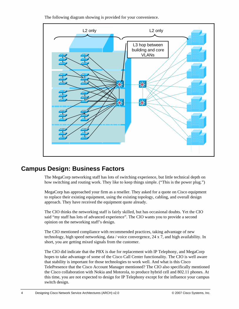
The present campus network uses a design recommended by their present switch vendor, who is no longer in business. The design uses stackable switches in a daisy-chain in each closet. The end switches in each daisy chain connect to a pair of building switches. Spanning tree is disabled in the closets – the switches detect link state loss and only activate one of the two uplinks at a time. Access ports are 10 Mbps and uplinks 100 Mbps in many cases.
The two building switches are connected with a trunk to each other. Each building switch connects back to one of the two core switches. The core switches have a link between them and operate at Layer 2 only. All the uplinks and the connecting link are in one VLAN. The building switches route the building subnets into the one core VLAN, which every building switch is connected to.
The present design uses one VLAN per department. Real-estate “wars” have led to departments being spread over different parts of different floors in each building. Shuffling ports to different VLANs to support personnel moves keeps several recent technical institute grads busy.
MegaCorp thinks their current network is very stable. They only have an outage every month or two, and staff can usually fix them within an hour by turning off one of the two building switches. In the evening, they power it up, and disconnect switches until the STP problem is found. The staff doesn’t mind the overtime pay.
4 Designing Cisco Network Service Architectures (ARCH) v2.0 © 2007 Cisco Systems, Inc.
The following diagram showing is provided for your convenience.
L2 only L2 only
L3 hop between building and core
VLANs
Campus Design: Business Factors The MegaCorp networking staff has lots of switching experience, but little technical depth on how switching and routing work. They like to keep things simple. (“This is the power plug.”)
MegaCorp has approached your firm as a reseller. They asked for a quote on Cisco equipment to replace their existing equipment, using the existing topology, cabling, and overall design approach. They have received the equipment quote already.
The CIO thinks the networking staff is fairly skilled, but has occasional doubts. Yet the CIO said “my staff has lots of advanced experience”. The CIO wants you to provide a second opinion on the networking staff’s design.
The CIO mentioned compliance with recommended practices, taking advantage of new technology, high speed networking, data / voice convergence, 24 x 7, and high availability. In short, you are getting mixed signals from the customer.
The CIO did indicate that the PBX is due for replacement with IP Telephony, and MegaCorp hopes to take advantage of some of the Cisco Call Center functionality. The CIO is well aware that stability is important for those technologies to work well. And what is this Cisco TelePresence that the Cisco Account Manager mentioned? The CIO also specifically mentioned the Cisco collaboration with Nokia and Motorola, to produce hybrid cell and 802.11 phones. At this time, you are not expected to design for IP Telephony except for the influence your campus switch design.
© 2007Cisco Systems, Inc. Lab Guide 5
The company is now using the offices from 6 AM to 12 midnight, with different people working different hours to service customers in different time zones. Many cubicles are virtualized or used for hoteling, with different occupants at different times or on different days.
MegaCorp prides itself on providing good customer service.
Campus Design: Technical Factors You conducted a network baseline. The baseline monitoring indicates that there is a moderate degree of STP instability in the current network. This causes bursts of 50 second outages that employees do not complain about, because they have gotten so used to them. There is evidence that the 100 Mbps uplinks from the closets are congested.
The technical staff think Cisco VTP sounds interesting, as it might save having to create VLANs on switches to support moves, adds, changes.
The CIO wants more availability than MegaCorp has at present, and has specifically asked for a design using three building switches instead of two, to get better availability.
The network staff asked that the switches quoted be “IPT and wireless ready”, whatever that means.
The draft Bill of Materials given you by the technical staff indicates a plan for all switches to be equipped for Power over Ethernet (PoE) on all ports. They also asked for an option for equipment without PoE since power injectors sound less costly to some of the lead technical staff.
6 Designing Cisco Network Service Architectures (ARCH) v2.0 © 2007 Cisco Systems, Inc.
MegaCorp Campus Design TasksComplete these steps:
Step 1 Determine what MegaCorp’s business and technical requirements really are (or should be), and how to convince MegaCorp that you are correct. (Do not spend a lot of time on this.)
_______________________________________________________________
_______________________________________________________________
_______________________________________________________________
Step 2 Determine a recommended design, and its pros and cons, as well as how it improves the current MegaCorp design. Diagram the design, and use bullet lists to itemize specifics. Be prepared to justify any changes to the MegaCorp plan that you propose. Include in your plans:
Physical topology (port counts, links, and link speeds, diagrams)
Logical topology (VLAN locations and scopes, Layer 2, Layer 3, other protocols (VTP, STP choice, STP settings, routing protocol, First Hop Routing Protocol, etc.)
Recommended switch models and alternatives
Other significant details
Plans for IP Telephony support
Recommendation for PoE
_______________________________________________________________
_______________________________________________________________
_______________________________________________________________
Step 3 Identify other technical design elements that the detailed design should include (e.g. type of STP, security measures, etc.)
_______________________________________________________________
_______________________________________________________________
_______________________________________________________________
Step 4 Provide a high level plan for how the network could be smoothly migrated over to the new equipment over several months.
_______________________________________________________________
_______________________________________________________________
_______________________________________________________________
© 2007 Cisco Systems, Inc. Lab Guide 7
Step 5 If the client insists on “just modernizing equipment” by replacing the existing switches with Cisco switches in their present design and extending to 3 building switches instead of 2, what can you do to mitigate any negative aspects of the design? (Identify the aspects you feel are risky or negative, and then how you propose to reduce the related risk.)
_______________________________________________________________
_______________________________________________________________
_______________________________________________________________
The Design Requirements ChangePartway through preparing your design write-up, proposal, and presentation MegaCorp tells you that the plan has changed. MegaCorp is acquiring a nearby company, whose name cannot be disclosed. The other company has five buildings not too far away, each with a switched network. They are currently interconnected by T1 links and routers. MegaCorp wants your proposal to include a design for incorporating the other sites. The CIO just got a sales pitch and wants the design to use a local Metro Ethernet service which provides FastEthernet multi-point Ethernet service to connect to the other sites. All the CIO can tell you is that the multi-point Ethernet is completely transparent, like connecting into a large Ethernet switch. The offering provides 100 Mbps or 1 Gbps connectivity, and sites do not all need to be connected at the same speed.
Step 6 Without knowing more about the Metro Ethernet service, you can think of it as being more or less like standard Ethernet connecting to some other switched buildings. How does this impact your design? What do you propose? Can you fit the acquired locations into your previous design?
_______________________________________________________________
_______________________________________________________________
_______________________________________________________________
Note One sign of a good design is that it readily accommodates changes and new requirements.
8 Designing Cisco Network Service Architectures (ARCH) v2.0 © 2007 Cisco Systems, Inc.
Activity Verification Your group has completed this activity when you have completed answers to the above questions, and selected a presenter for the group.
The presenter should be prepared to explain and defend your answers to the class. The topics for discussion include the following:
What you think are the requirements for MegaCorps, and the justification for your answers
Your diagram, etc. for the best design
Your list of pros and cons for the best design, and how it improves the current MegaCorp (proposed) design. (See the list of detailed items to provide above.)
Your justifications for any changes to the MegaCorp plan that you propose.
Your list of other technical design factors the detailed design should incorporate
Your high-level migration plan.
Your plan for how to mitigate risks in a “modern equipment” version of the MegaCorp current design.
Your proposal for how to accommodate the Metro Ethernet and acquisition into your design, and justification for the main elements you propose.
© 2007 Cisco Systems, Inc. Lab Guide 9
Case Study 2: CP Hotels Addressing and Routing Design
This case study enables you to practice the skills and knowledge learned in the modules up to this point, especially the “Advanced Addressing and Routing Design” lesson. Any technology we have not yet discussed is used in only minor ways where superficial knowledge or the information provided within the case study should suffice.
This case study is based on a fictional company, CP Hotels. CP Hotels is a rapidly-growing hotel organization providing services to a family of 8 hotel brand names such as SuiteSpotTM, CheapStayTM, El QuartoTM, and PurpleRoof InnTM. The brands are different corporate divisions with different cost structures and networking requirements, serviced by the shared IT organization. Each brand provides different pricing and customer amenities (premium service versus low cost, single room versus suite, etc.).
You represent a Cisco Partner called in to review the existing CP Hotels addressing and routing design, and provide recommendations for improvement.
We normally try to use private addressing in case studies. In this case study, we use some fictional public IP address blocks for clarity and a real-world flavor.
Activity Objective In this activity, you will critically review, redesign, and create new parts of an IP addressing and routing design for CP Hotels.
After completing this activity, you will be able to meet these objectives:
Examine and critique a moderately complex IP addressing scheme, and propose how to improve it.
Examine and critique a moderately complex routing scheme, and propose how to improve it.
Evaluate and improve the current route redistribution scheme. Evaluate and improve the current default routing scheme.
Propose a new addressing scheme to provide out-of-band NAC roles and voice VLANs in the four HQ buildings.
Discuss the impact of moving web servers to collocation facilities, and propose a design for how to best connect them back to the data centers, and how to best perform routing to them.
Visual Objective There is no visual objective for this case study.
10 Designing Cisco Network Service Architectures (ARCH) v2.0 © 2007 Cisco Systems, Inc.
Required Resources These are the resources and equipment required to complete this activity:
Case study guidelines, presented in the Course Introduction
CP Hotels Case Study Scenario
A workgroup consisting of two to four students
Blank sheets of paper and a pencil
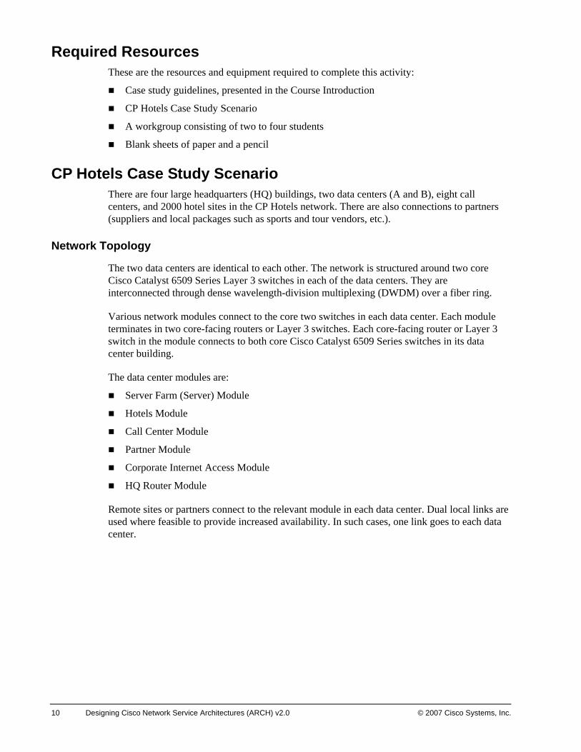
CP Hotels Case Study Scenario There are four large headquarters (HQ) buildings, two data centers (A and B), eight call centers, and 2000 hotel sites in the CP Hotels network. There are also connections to partners (suppliers and local packages such as sports and tour vendors, etc.).
Network Topology
The two data centers are identical to each other. The network is structured around two core Cisco Catalyst 6509 Series Layer 3 switches in each of the data centers. They are interconnected through dense wavelength-division multiplexing (DWDM) over a fiber ring.
Various network modules connect to the core two switches in each data center. Each module terminates in two core-facing routers or Layer 3 switches. Each core-facing router or Layer 3 switch in the module connects to both core Cisco Catalyst 6509 Series switches in its data center building.
The data center modules are:
Server Farm (Server) Module
Hotels Module
Call Center Module
Partner Module
Corporate Internet Access Module
HQ Router Module
Remote sites or partners connect to the relevant module in each data center. Dual local links are used where feasible to provide increased availability. In such cases, one link goes to each data center.
© 2007 Cisco Systems, Inc. Lab Guide 11
The following diagram illustrates the CP Hotels network topology at a high level:
Data Center B
Data Center A
(Identical layout)
HQ 1 & 2
HQ 3 & 4
HQ Module
HQ 1 & 2
HQ 3 & 4
HQ Module
Corporate Internet Access
Internet
Corporate Internet Access
InternetInternet
Hotels Module
Core Aggregation (4 pairs)L2 connectivity
(shared)Access (4 groups
of 4, 16 total)
FrameRelayFrameRelayTo 2000 hotels
Partner Module
PartnersPartners
Various connection
methods
Call Center Module
MPLS VPN
Call Center Module
MPLS VPN
MPLS VPN
Core
Server Farm Module
Aggregation Access Rows of racks of servers
x 8
x 8
Mainframe & website DMZ also located here
InternetInternet
12 Designing Cisco Network Service Architectures (ARCH) v2.0 © 2007 Cisco Systems, Inc.
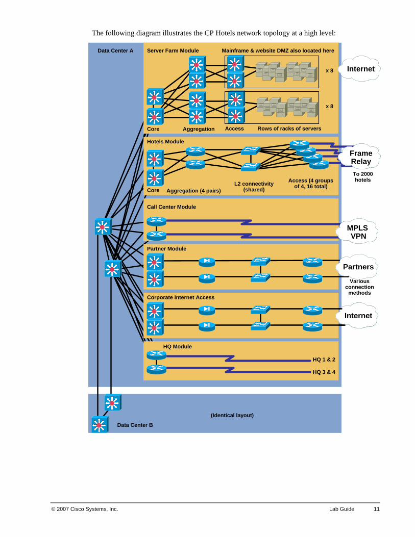
Server Farm Module In each data center, there are many servers organized into rows. Each server row is connects to a pair of Cisco Catalyst 6509 Series access switches placed at the end of the row. Eight server rows connect to a pair of Layer 3 Cisco Catalyst 6509 Series aggregation switches using 4 Gbps EtherChannel. Although a smaller chassis might have been used for the aggregation switches, this approach keeps the equipment model inventory simple and allows space for NAM blades and service modules.
There are currently two pairs of aggregation switches (two aggregation modules of 8 rows each) connecting to the core server switches by 4 Gbps EtherChannel.
The corporate mainframes also connect to switches via Gigabit connections. They run IBM OSA, which uses OSPF to route traffic to the rest of the network, mainly to detect and respond to Gigabit link failure. They connect directly to aggregation layer switches in one of the two aggregation modules.
The corporate public-facing web and e-commerce servers are in a DMZ complex connected to one pair of access switches in the server farm area. They produce a high volume of traffic, all local to the server module. Separate dedicated high-speed Internet connections connect to the outside of the firewalls in the DMZ complex. All servers, mainframes, and web servers are duplicated at the second data center site.
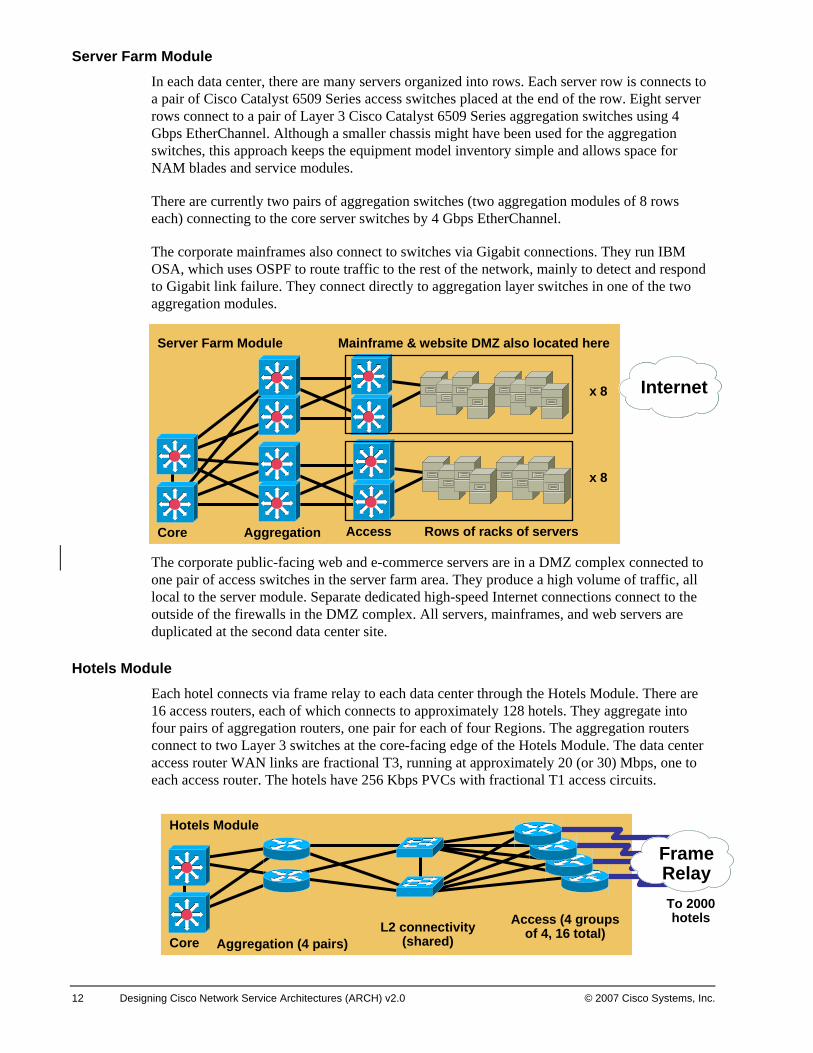
Hotels Module Each hotel connects via frame relay to each data center through the Hotels Module. There are 16 access routers, each of which connects to approximately 128 hotels. They aggregate into four pairs of aggregation routers, one pair for each of four Regions. The aggregation routers connect to two Layer 3 switches at the core-facing edge of the Hotels Module. The data center access router WAN links are fractional T3, running at approximately 20 (or 30) Mbps, one to each access router. The hotels have 256 Kbps PVCs with fractional T1 access circuits.
Core
Server Farm Module
Aggregation Access Rows of racks of servers
x 8
x 8
Mainframe & website DMZ also located here
Internet
Core
Server Farm Module
Aggregation Access Rows of racks of servers
x 8
x 8
Mainframe & website DMZ also located here
InternetInternet
Hotels Module
Core Aggregation (4 pairs)L2 connectivity
(shared)Access (4 groups
of 4, 16 total)
FrameRelayFrameRelayTo 2000 hotels
© 2007 Cisco Systems, Inc. Lab Guide 13
Note 128 x 256 Kbps is approximately 33 Mbps. So each data center access router needs some fraction of that bandwidth, depending on how much oversubscription is built into the network.
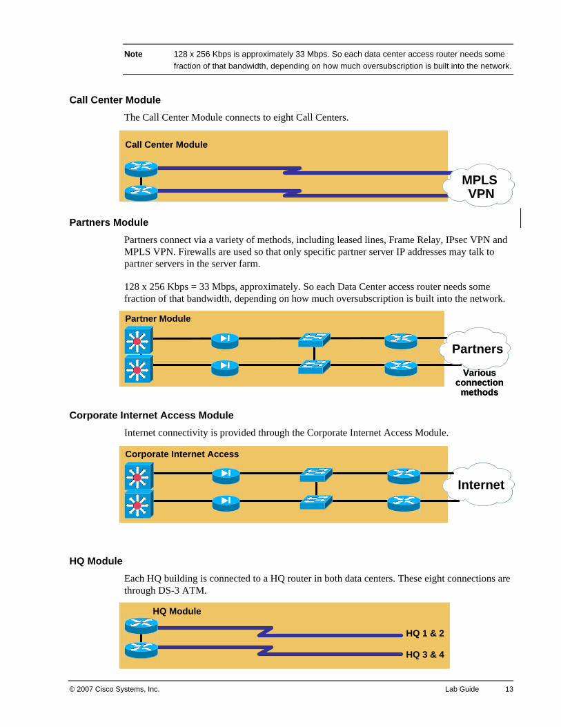
Call Center Module The Call Center Module connects to eight Call Centers.
Partners Module Partners connect via a variety of methods, including leased lines, Frame Relay, IPsec VPN and MPLS VPN. Firewalls are used so that only specific partner server IP addresses may talk to partner servers in the server farm.
128 x 256 Kbps = 33 Mbps, approximately. So each Data Center access router needs some fraction of that bandwidth, depending on how much oversubscription is built into the network.
Corporate Internet Access Module Internet connectivity is provided through the Corporate Internet Access Module.
HQ Module Each HQ building is connected to a HQ router in both data centers. These eight connections are through DS-3 ATM.
Call Center Module
MPLS VPN
Call Center Module
MPLS VPN
MPLS VPN
Partner Module
Partners
Various connection
methods
Partner Module
PartnersPartners
Various connection
methods
HQ 1 & 2
HQ 3 & 4
HQ Module
HQ 1 & 2
HQ 3 & 4
HQ Module
Corporate Internet Access
Internet
Corporate Internet Access
InternetInternet
14 Designing Cisco Network Service Architectures (ARCH) v2.0 © 2007 Cisco Systems, Inc.
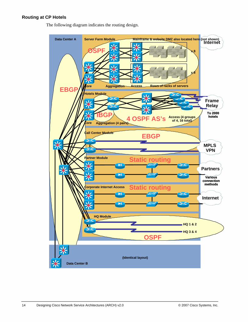
Routing at CP Hotels The following diagram indicates the routing design.
Internet
Data Center B
Data Center A
(Identical layout)
HQ 1 & 2
HQ 3 & 4
HQ Module
Corporate Internet Access
Partner Module
Call Center Module
Hotels Module
Internet
Partners
MPLS VPN
Core Aggregation (4 pairs)
Access (4 groups of 4, 16 total)
FrameRelayTo 2000 hotels
Various connection
methods
Core
Server Farm Module
Aggregation Access Rows of racks of servers
x 8
x 8
Mainframe & website DMZ also located here (not shown)
EBGP
OSPF
EBGP
Static routing
Static routing
4 OSPF AS’sIBGP
OSPFInternetInternet
Data Center B
Data Center A
(Identical layout)
HQ 1 & 2
HQ 3 & 4
HQ Module
Corporate Internet Access
Partner Module
Call Center Module
Hotels Module
InternetInternet
PartnersPartners
MPLS VPN
MPLS VPN
Core Aggregation (4 pairs)
Access (4 groups of 4, 16 total)
FrameRelayFrameRelayTo 2000 hotels
Various connection
methods
Core
Server Farm Module
Aggregation Access Rows of racks of servers
x 8
x 8
Mainframe & website DMZ also located here (not shown)
EBGP
OSPF
EBGP
Static routing
Static routing
4 OSPF AS’sIBGP
OSPF
© 2007 Cisco Systems, Inc. Lab Guide 15
The routing design uses external Border Gateway protocol (EBGP) to isolate routing in the various modules. Most modules use Open Shortest Path First (OSPF) within the module. Each module has a different private BGP autonomous system (AS) number, to simplify writing BGP policy rules. The module pair of routers uses EBGP to the two core routers in each data center. Each module router peers with both core routers in its data center. The two data center core pairs each have different BGP AS numbers and also use EBGP to the other data center pair.
Each module router pair redistributes the relevant Interior Gateway Protocol (IGP) into BGP. Default is injected into the IGP in each module, so that default points to the core (which then routes to the dedicated Internet links).
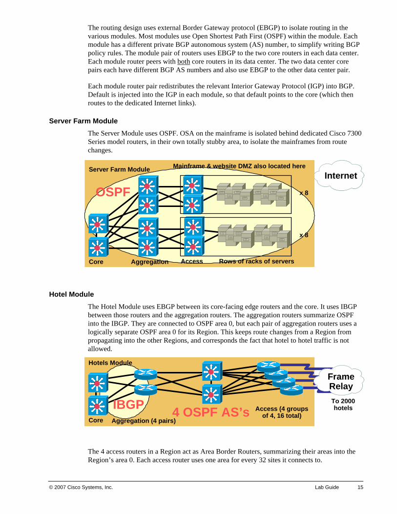
Server Farm Module The Server Module uses OSPF. OSA on the mainframe is isolated behind dedicated Cisco 7300 Series model routers, in their own totally stubby area, to isolate the mainframes from route changes.
Hotel Module The Hotel Module uses EBGP between its core-facing edge routers and the core. It uses IBGP between those routers and the aggregation routers. The aggregation routers summarize OSPF into the IBGP. They are connected to OSPF area 0, but each pair of aggregation routers uses a logically separate OSPF area 0 for its Region. This keeps route changes from a Region from propagating into the other Regions, and corresponds the fact that hotel to hotel traffic is not allowed.
The 4 access routers in a Region act as Area Border Routers, summarizing their areas into the Region’s area 0. Each access router uses one area for every 32 sites it connects to.
InternetInternet
Core
Server Farm Module
Aggregation Access Rows of racks of servers
x 8
x 8
Mainframe & website DMZ also located here
OSPF
Hotels Module
Core Aggregation (4 pairs)
Access (4 groups of 4, 16 total)
FrameRelayFrameRelayTo 2000 hotels4 OSPF AS’sIBGP
16 Designing Cisco Network Service Architectures (ARCH) v2.0 © 2007 Cisco Systems, Inc.
Note This frame relay design approach gives us 5 areas per ABR (128/32 = 4, plus area 0). This was very aggressive design as of 5-10 years ago, when 3 areas on one router was considered aggressive. One alternative would have been to put 64 hotels per area. This alternative would however waste more bandwidth on LSA flooding within each area. For purposes of this Case Study, we will stick with the aggressive OSPF design is used.
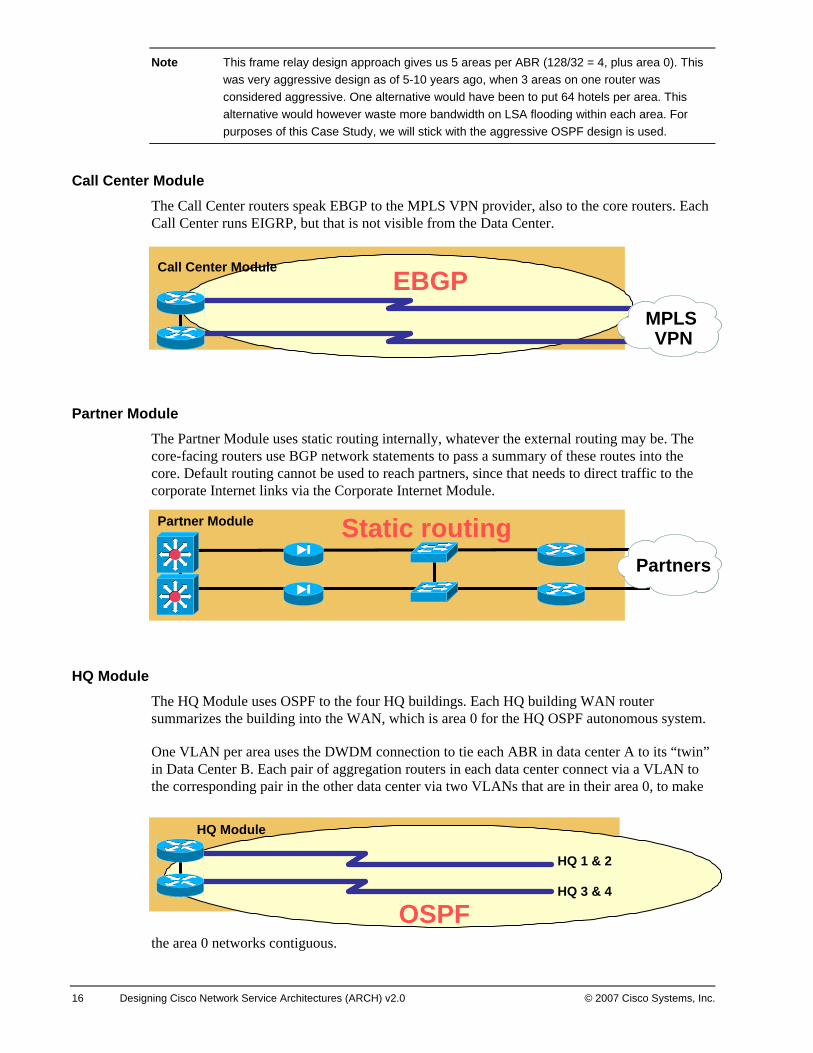
Call Center Module The Call Center routers speak EBGP to the MPLS VPN provider, also to the core routers. Each Call Center runs EIGRP, but that is not visible from the Data Center.
Partner Module The Partner Module uses static routing internally, whatever the external routing may be. The core-facing routers use BGP network statements to pass a summary of these routes into the core. Default routing cannot be used to reach partners, since that needs to direct traffic to the corporate Internet links via the Corporate Internet Module.
HQ Module The HQ Module uses OSPF to the four HQ buildings. Each HQ building WAN router summarizes the building into the WAN, which is area 0 for the HQ OSPF autonomous system.
One VLAN per area uses the DWDM connection to tie each ABR in data center A to its “twin” in Data Center B. Each pair of aggregation routers in each data center connect via a VLAN to the corresponding pair in the other data center via two VLANs that are in their area 0, to make
the area 0 networks contiguous.
Call Center Module
MPLS VPN
MPLS VPN
EBGP
Partner Module
PartnersPartners
Static routing
HQ 1 & 2
HQ 3 & 4
HQ Module
OSPF
© 2007 Cisco Systems, Inc. Lab Guide 17
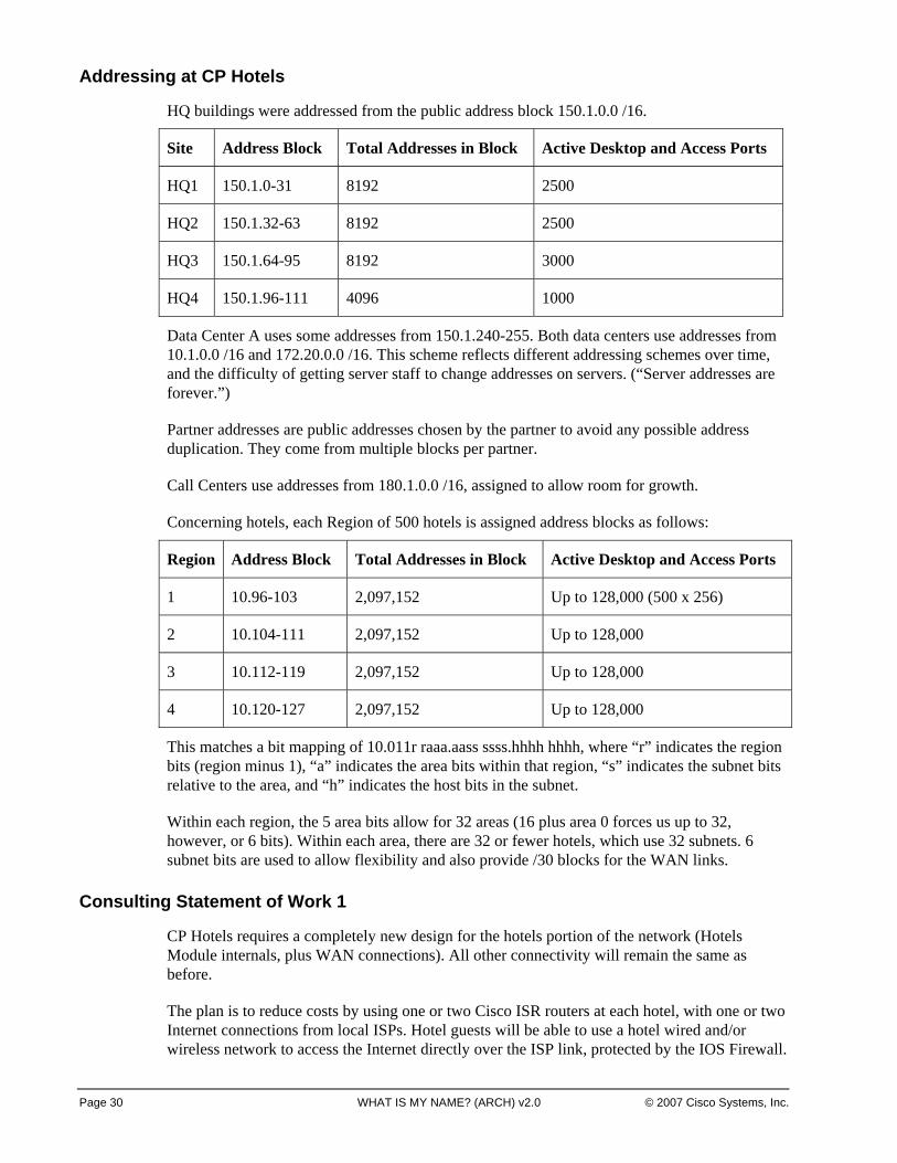
Addressing at CP Hotels
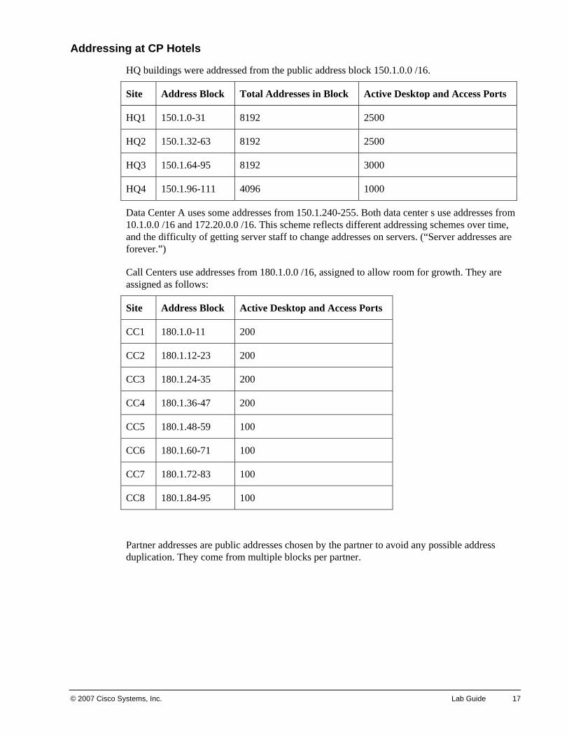
HQ buildings were addressed from the public address block 150.1.0.0 /16.
Site Address Block Total Addresses in Block Active Desktop and Access Ports
HQ1 150.1.0-31 8192 2500
HQ2 150.1.32-63 8192 2500
HQ3 150.1.64-95 8192 3000
HQ4 150.1.96-111 4096 1000
Data Center A uses some addresses from 150.1.240-255. Both data center s use addresses from 10.1.0.0 /16 and 172.20.0.0 /16. This scheme reflects different addressing schemes over time, and the difficulty of getting server staff to change addresses on servers. (“Server addresses are forever.”)
Call Centers use addresses from 180.1.0.0 /16, assigned to allow room for growth. They are assigned as follows:
Site Address Block Active Desktop and Access Ports
CC1 180.1.0-11 200
CC2 180.1.12-23 200
CC3 180.1.24-35 200
CC4 180.1.36-47 200
CC5 180.1.48-59 100
CC6 180.1.60-71 100
CC7 180.1.72-83 100
CC8 180.1.84-95 100
Partner addresses are public addresses chosen by the partner to avoid any possible address duplication. They come from multiple blocks per partner.
18 Designing Cisco Network Service Architectures (ARCH) v2.0 © 2007 Cisco Systems, Inc.
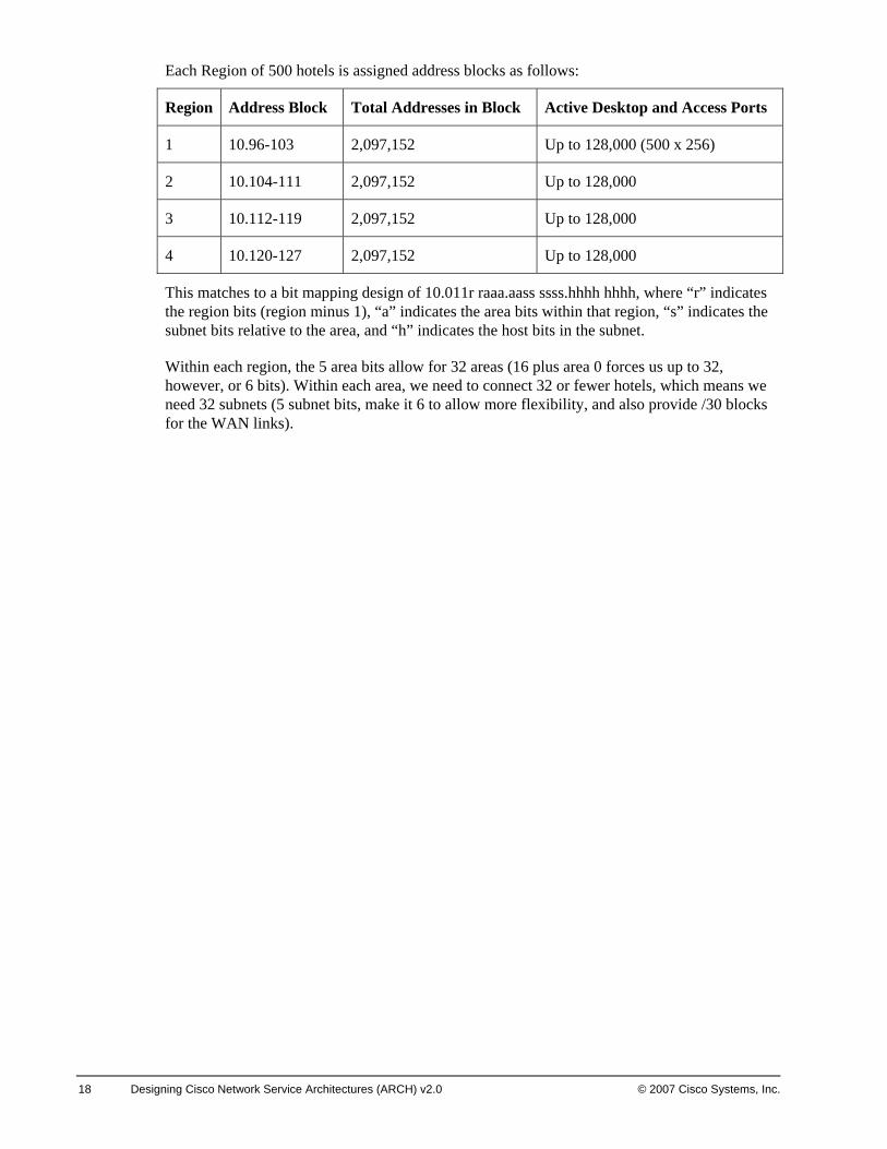
Each Region of 500 hotels is assigned address blocks as follows:
Region Address Block Total Addresses in Block Active Desktop and Access Ports
1 10.96-103 2,097,152 Up to 128,000 (500 x 256)
2 10.104-111 2,097,152 Up to 128,000
3 10.112-119 2,097,152 Up to 128,000
4 10.120-127 2,097,152 Up to 128,000
This matches to a bit mapping design of 10.011r raaa.aass ssss.hhhh hhhh, where “r” indicates the region bits (region minus 1), “a” indicates the area bits within that region, “s” indicates the subnet bits relative to the area, and “h” indicates the host bits in the subnet.
Within each region, the 5 area bits allow for 32 areas (16 plus area 0 forces us up to 32, however, or 6 bits). Within each area, we need to connect 32 or fewer hotels, which means we need 32 subnets (5 subnet bits, make it 6 to allow more flexibility, and also provide /30 blocks for the WAN links).
© 2007 Cisco Systems, Inc. Lab Guide 19
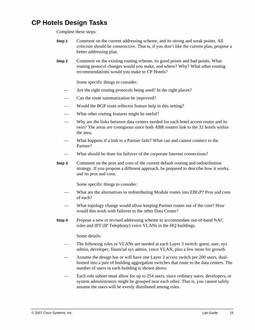
CP Hotels Design TasksComplete these steps:
Step 1 Comment on the current addressing scheme, and its strong and weak points. All criticism should be constructive. That is, if you don’t like the current plan, propose a better addressing plan.
Step 2 Comment on the existing routing scheme, its good points and bad points. What routing protocol changes would you make, and where? Why? What other routing recommendations would you make to CP Hotels?
Some specific things to consider:
— Are the right routing protocols being used? In the right places?
— Can the route summarization be improved?
— Would the BGP route reflector feature help in this setting?
— What other routing features might be useful?
— Why are the links between data centers needed for each hotel access router and its twin? The areas are contiguous since both ABR routers link to the 32 hotels within the area.
— What happens if a link to a Partner fails? What can and cannot connect to the Partner?
— What should be done for failover of the corporate Internet connections?
Step 3 Comment on the pros and cons of the current default routing and redistribution strategy. If you propose a different approach, be prepared to describe how it works, and its pros and cons.
Some specific things to consider:
— What are the alternatives to redistributing Module routes into EBGP? Pros and cons of each?
— What topology change would allow keeping Partner routes out of the core? How would this work with failover to the other Data Center?
Step 4 Propose a new or revised addressing scheme to accommodate out-of-band NAC roles and IPT (IP Telephony) voice VLANs in the HQ buildings.
Some details:
— The following roles or VLANs are needed at each Layer 3 switch: guest, user, sys admin, developer, financial sys admin, voice VLAN, plus a few more for growth.
— Assume the design has or will have one Layer 3 access switch per 200 users, dual-homed into a pair of building aggregation switches that route to the data centers. The number of users in each building is shown above.
— Each role subnet must allow for up to 254 users, since ordinary users, developers, or system administrators might be grouped near each other. That is, you cannot safely assume the users will be evenly distributed among roles.
Page 20 WHAT IS MY NAME? (ARCH) v2.0 © 2007 Cisco Systems, Inc.
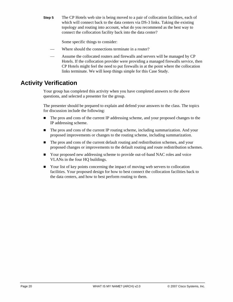
Step 5 The CP Hotels web site is being moved to a pair of collocation facilities, each of which will connect back to the data centers via DS-3 links. Taking the existing topology and routing into account, what do you recommend as the best way to connect the collocation facility back into the data center?
Some specific things to consider:
— Where should the connections terminate in a router?
— Assume the collocated routers and firewalls and servers will be managed by CP Hotels. If the collocation provider were providing a managed firewalls service, then CP Hotels might feel the need to put firewalls in at the point where the collocation links terminate. We will keep things simple for this Case Study.
Activity Verification Your group has completed this activity when you have completed answers to the above questions, and selected a presenter for the group.
The presenter should be prepared to explain and defend your answers to the class. The topics for discussion include the following:
The pros and cons of the current IP addressing scheme, and your proposed changes to the IP addressing scheme.
The pros and cons of the current IP routing scheme, including summarization. And your proposed improvements or changes to the routing scheme, including summarization.
The pros and cons of the current default routing and redistribution schemes, and your proposed changes or improvements to the default routing and route redistribution schemes.
Your proposed new addressing scheme to provide out-of-band NAC roles and voice VLANs in the four HQ buildings.
Your list of key points concerning the impact of moving web servers to collocation facilities. Your proposed design for how to best connect the collocation facilities back to the data centers, and how to best perform routing to them.
Page 21 Lab Guide © 2007 Cisco Systems, Inc.
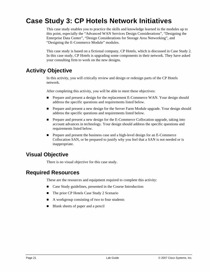
Case Study 3: CP Hotels Network Initiatives This case study enables you to practice the skills and knowledge learned in the modules up to this point, especially the “Advanced WAN Services Design Considerations”, “Designing the Enterprise Data Center”, “Design Considerations for Storage Area Networking”, and “Designing the E-Commerce Module” modules.
This case study is based on a fictional company, CP Hotels, which is discussed in Case Study 2. In this case study, CP Hotels is upgrading some components in their network. They have asked your consulting firm to work on the new designs.
Activity Objective In this activity, you will critically review and design or redesign parts of the CP Hotels network.
After completing this activity, you will be able to meet these objectives:
Prepare and present a design for the replacement E-Commerce WAN. Your design should address the specific questions and requirements listed below.
Prepare and present a new design for the Server Farm Module upgrade. Your design should address the specific questions and requirements listed below.
Prepare and present a new design for the E-Commerce Collocation upgrade, taking into account advances in technology. Your design should address the specific questions and requirements listed below.
Prepare and present the business case and a high-level design for an E-Commerce Collocation SAN, or be prepared to justify why you feel that a SAN is not needed or is inappropriate.
Visual Objective There is no visual objective for this case study.
Required Resources These are the resources and equipment required to complete this activity:
Case Study guidelines, presented in the Course Introduction
The prior CP Hotels Case Study 2 Scenario
A workgroup consisting of two to four students
Blank sheets of paper and a pencil
Page 22 WHAT IS MY NAME? (ARCH) v2.0 © 2007 Cisco Systems, Inc.
CP Hotels Case Study Scenario See Case Study 2 for a description of the current CP Hotels network.
Parts of the diagrams are replicated here for reference.
CP Hotels Web Site Topology
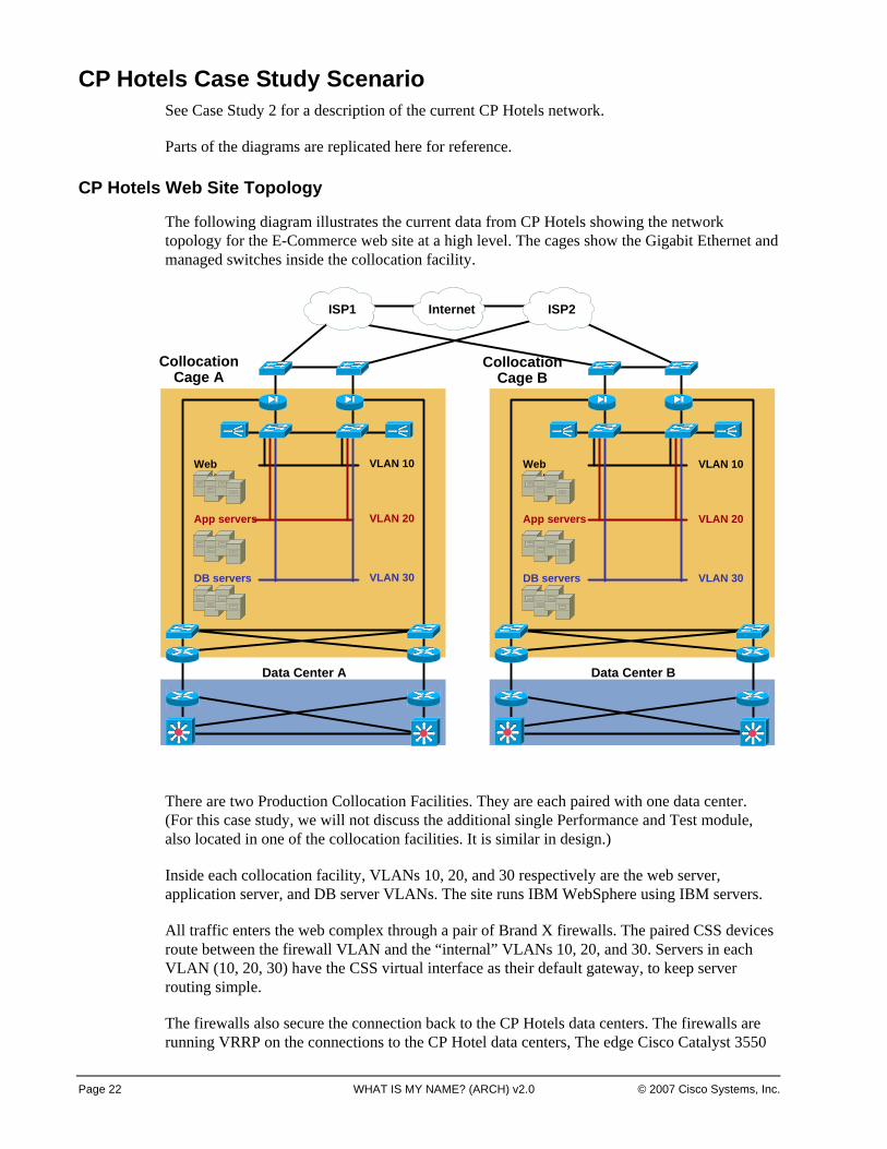
The following diagram illustrates the current data from CP Hotels showing the network topology for the E-Commerce web site at a high level. The cages show the Gigabit Ethernet and managed switches inside the collocation facility.
There are two Production Collocation Facilities. They are each paired with one data center. (For this case study, we will not discuss the additional single Performance and Test module, also located in one of the collocation facilities. It is similar in design.)
Inside each collocation facility, VLANs 10, 20, and 30 respectively are the web server, application server, and DB server VLANs. The site runs IBM WebSphere using IBM servers.
All traffic enters the web complex through a pair of Brand X firewalls. The paired CSS devices route between the firewall VLAN and the “internal” VLANs 10, 20, and 30. Servers in each VLAN (10, 20, 30) have the CSS virtual interface as their default gateway, to keep server routing simple.
The firewalls also secure the connection back to the CP Hotels data centers. The firewalls are running VRRP on the connections to the CP Hotel data centers, The edge Cisco Catalyst 3550
InternetInternet
Web servers
App servers
DB servers
ISP2ISP2ISP1ISP1
Collocation Cage A
Data Center A
Web servers
App servers
DB servers
VLAN 10
VLAN 20
VLAN 30
Collocation Cage B
Data Center B
VLAN 10
VLAN 20
VLAN 30
Page 23 Lab Guide © 2007 Cisco Systems, Inc.
Series switches use HSRP and EIGRP to the edge WAN routers connecting to the data centers. The Cisco Catalyst 3550 Series switches also provide a SPAN port for troubleshooting. The firewalls and Cisco Catalyst 3550 Series switches have static routes pointed at each other’s VIP addresses.
There are two WAN routers at each E-Commerce web site. Each WAN router has a DS-3 connection back to one router at the paired Data Center. The data center WAN routers connect back to aggregation layer switches inside the Server Farm Module in that data center.
CP Hotels Server Farm Topology
As you know (you designed it!), the Server Farm topology is as follows.
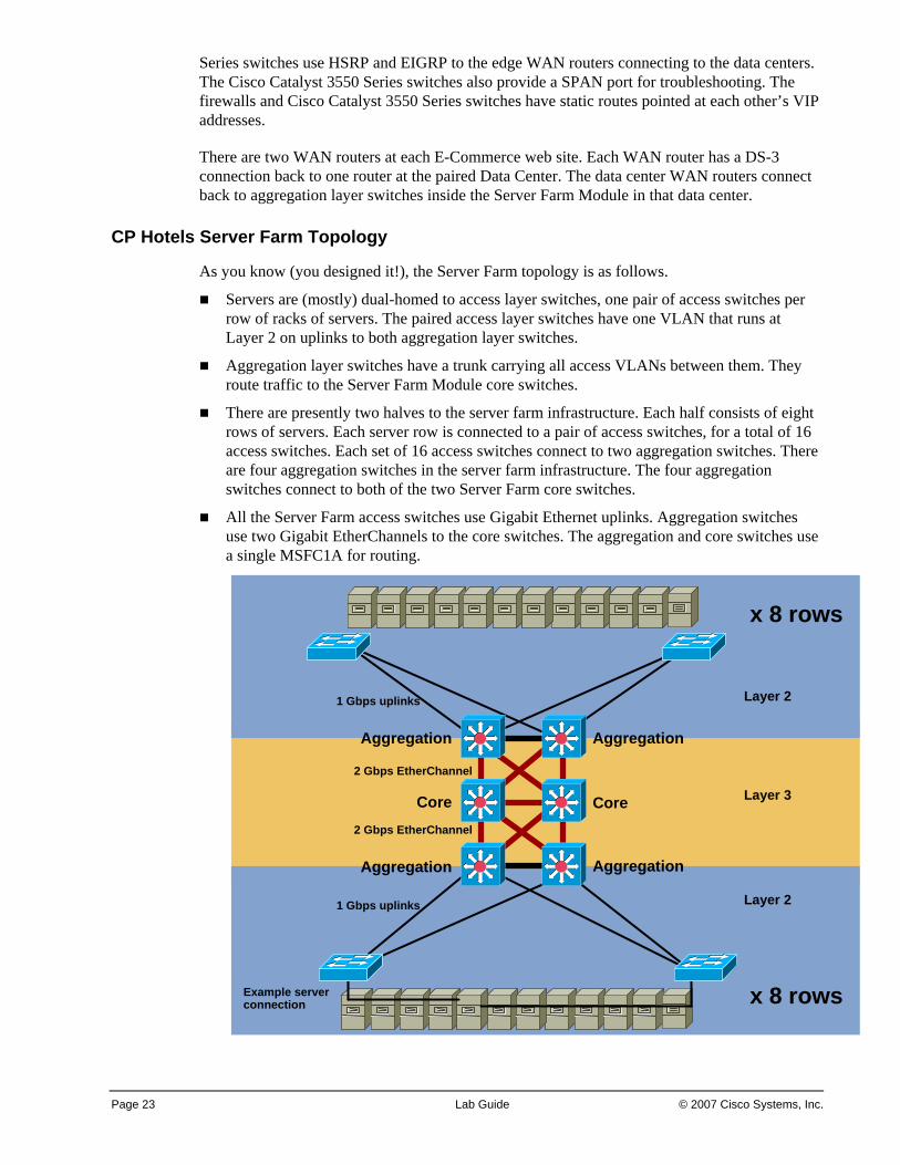
Servers are (mostly) dual-homed to access layer switches, one pair of access switches per row of racks of servers. The paired access layer switches have one VLAN that runs at Layer 2 on uplinks to both aggregation layer switches.
Aggregation layer switches have a trunk carrying all access VLANs between them. They route traffic to the Server Farm Module core switches.
There are presently two halves to the server farm infrastructure. Each half consists of eight rows of servers. Each server row is connected to a pair of access switches, for a total of 16 access switches. Each set of 16 access switches connect to two aggregation switches. There are four aggregation switches in the server farm infrastructure. The four aggregation switches connect to both of the two Server Farm core switches.
All the Server Farm access switches use Gigabit Ethernet uplinks. Aggregation switches use two Gigabit EtherChannels to the core switches. The aggregation and core switches use a single MSFC1A for routing.
Example server connection
1 Gbps uplinks
2 Gbps EtherChannel
2 Gbps EtherChannel
1 Gbps uplinks
Aggregation
Aggregation Aggregation
Aggregation
CoreCore
x 8 rows
x 8 rows
Layer 2
Layer 2
Layer 3
Page 24 WHAT IS MY NAME? (ARCH) v2.0 © 2007 Cisco Systems, Inc.
CP Hotels Design Tasks Complete these steps:
Step 1 (E-Commerce WAN Statement of Work) CP Hotels’ website is experiencing 50% growth in traffic back to the Data Centers every year. The current links are at 80% utilization, so that if one fails, the other will not have enough capacity. Assuming all the old and new WAN technologies are available, recommend an updated E-Commerce WAN design.
Be sure to address the following:
— Are there any WAN technologies that should clearly be ruled out? If so, why?
— Are there any WAN technologies that are particularly suitable for this use?
— Is there an approach that would provide the ability to “turn up the bandwidth” without new hardware or access circuits?
— How much bandwidth do you recommend that CP Hotels start out with on the replacement WAN links?
— What SLA characteristics are needed for these links, if CP Hotels views them as part of the highly critical revenue-producing e-commerce site?
Step 2 (Server Farm Statement of Work) CP Hotels is asking you, as their favorite and highly-skilled consultant, to comment on the data center Server Farm Module design.
— Management has asked for a “green field” re-design of the Server Farm module from scratch. As you know from some late nights, there have been several “configuration accidents” and the odd hardware problem leading to large Spanning Tree loops. Management would like to “add another 9 of availability” for the server farm network.
— The CIO emphasized that the new design should take advantage of technology and speed improvements, while complying with shifts in what are considered Best Practices.
— The CP Hotels server administrators discovered VMWare about 2 years ago, and started rolling it into large-scale production use about 9 months ago. As you know, VMWare allows one physical server to be divided into multiple logical servers, providing isolation for different applications with a heavy hardware investment for “one application, one server”. They have been testing VMotion, which can “snapshot” a virtual server and move it to another physical server in about 1 second, without having to take it out of service. Their VMotion consultant is telling them the best way to deploy VMotion is to use one or two dedicated interface(s) per server, on a dedicated VLAN, to ensure rapid problem-free moves without contention from data traffic. Many rows of racks are full, however, so any “unused” servers for VMotion could be anywhere in the data center. Space at row ends is tight, so CP Hotels cannot just add some spare racks and servers to the existing rows.
— CP Hotels wants your recommendation on how to accommodate the VMotion requirements while meeting the first goal of “adding another 9 of availability”.
Page 25 Lab Guide © 2007 Cisco Systems, Inc.
Step 3 (E-Commerce Redesign Statement of Work) The hardware in the Collocation Facility is coming off lease, and the E-Commerce manager has the budget to “do it well”. You have been asked to come up with a proposed design, meeting the following requirements:
— Firewall support is desired between web and application, application and database layers. That way, a server compromise in one layer might be contained before it affects the other layers.
— If there is a good way to protect servers within a VLAN from each other, CP Hotels would like to know about it.
— The CIO emphasized that the new design should take advantage of technology and speed improvements, while complying with shifts in what are considered recommended practices.
— Simplicity and low device count matter – collocation space is costly, and tight.
— The web site is doubling in traffic volume every year. The design needs to scale to cover growth over the next 4-5 years.
— There is talk of the collocation provider managing the devices within its site, so appropriate security is needed inside the data centers in case there is a lapse in the security they provide.
— Do not forget to put in IPS capability.
— After losing millions of dollars due to a single extended outage, management has purchased the Network General Infinistream product, which does packet capture and reporting based on terabytes of disk space. The intent is to use it as a “network flight record” to help analyze the next outage. Your design will need to provide SPAN ports and “plumbing” so that the Infinistream can capture every packet every device in the collocation facility transmits on the inside of the firewall.
Step 4 SAN Business Case and High-Level Design for Collocation Facilities
— All web pages and application and database files are static, used to generate responses to web queries. Some of the databases are refreshed nightly, others change monthly, reflecting new hotel locations, etc. Actual guest reservations, frequent traveler benefits, and so on are stored in databases within the data center, not the collocation facility.
— At a very high level, what might be some business or technical reasons for using SAN in the collocation facilities? If you think a SAN is not needed or inappropriate, prepare to justify this.
— How would you describe your SAN design at a high level, taking the above security requirements into account?
Page 26 WHAT IS MY NAME? (ARCH) v2.0 © 2007 Cisco Systems, Inc.
Activity Verification Your group has completed this activity when you have completed answers to the above questions, and selected a presenter for the group.
The presenter should be prepared to explain and defend your answers to the class. The topics for discussion include the following:
Prepare and present a design for the replacement E-Commerce WAN. Your design should address the specific questions and requirements listed below.
Prepare and present a new design for the Server Farm Module upgrade. Your design should address the specific questions and requirements listed below.
Prepare and present a new design for the E-Commerce Collocation upgrade, taking into account advances in technology. Your design should address the specific questions and requirements listed below.
Prepare and present the business case and a high-level design for an E-Commerce collocation SAN, or be prepared to justify why you feel that a SAN is not needed or inappropriate. Your design should address the specific questions and requirements listed below.
Page 27 Lab Guide © 2007 Cisco Systems, Inc.
Case Study 4: CP Hotels Security and IPsec VPN Network
This case study enables you to practice the skills and knowledge learned in the modules up to this point, especially the “Security Services Design” and the “IPsec and SSL VPN Design” modules.
This case study is based on a fictional company, CP Hotels, discussed in a previous case study.
You represent a Cisco Partner called in to review the existing CP Hotels addressing and routing design, and provide recommendations for improvement.
We normally try to use private addressing in case studies. In this case study, we use some fictional public IP address blocks for clarity and a real-world flavor.
Activity Objective In this activity, you will critically review and/or redesign key portions of the CP Hotels network, using your new Security and IPsec VPN design skills.
After completing this activity, you will be able to meet these objectives:
Recommend what type of IPsec VPN CP Hotels should use, and present the pros, cons, and justification for your recommendation. Determine and present a detailed design for the hotel IPsec VPN, including overall hotel routing with failover, how IPsec reaches the other tunnel endpoint, and detailed IP addressing plan.
Critically review and make recommendations to improve security at CP Hotels, including specific items listed below.
Determine and present a design for Network Admission Control (NAC) Appliance deployment in CP Hotels headquarters (HQ) buildings, including coverage of specific items listed below.
Visual Objective There is no visual objective for this case study.
Required Resources These are the resources and equipment required to complete this activity:
Case Study guidelines, presented in the Course Introduction
Previous CP Hotels IP Addressing and Routing Case Study Scenario
A workgroup consisting of two to four students
Blank sheets of paper and a pencil
CP Hotels Case Study Scenario See Case Study 2 for a description of the current CP Hotels network. The diagrams are provided in this case study for ease of reference.
Page 28 WHAT IS MY NAME? (ARCH) v2.0 © 2007 Cisco Systems, Inc.
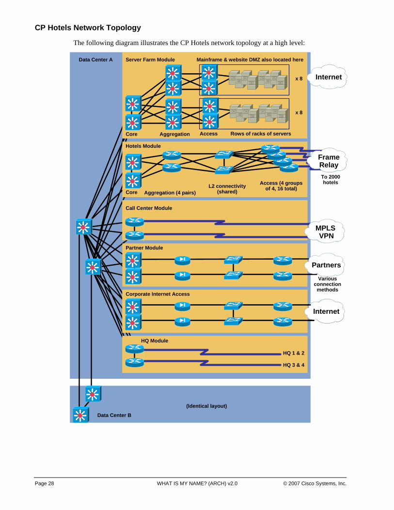
CP Hotels Network Topology
The following diagram illustrates the CP Hotels network topology at a high level:
Data Center B
Data Center A
(Identical layout)
HQ 1 & 2
HQ 3 & 4
HQ Module
HQ 1 & 2
HQ 3 & 4
HQ Module
Corporate Internet Access
Internet
Corporate Internet Access
InternetInternet
Hotels Module
Core Aggregation (4 pairs)L2 connectivity
(shared)Access (4 groups
of 4, 16 total)
FrameRelayFrameRelayTo 2000 hotels
Partner Module
PartnersPartners
Various connection
methods
Call Center Module
MPLS VPN
Call Center Module
MPLS VPN
MPLS VPN
Core
Server Farm Module
Aggregation Access Rows of racks of servers
x 8
x 8
Mainframe & website DMZ also located here
InternetInternet
Page 29 Lab Guide © 2007 Cisco Systems, Inc.
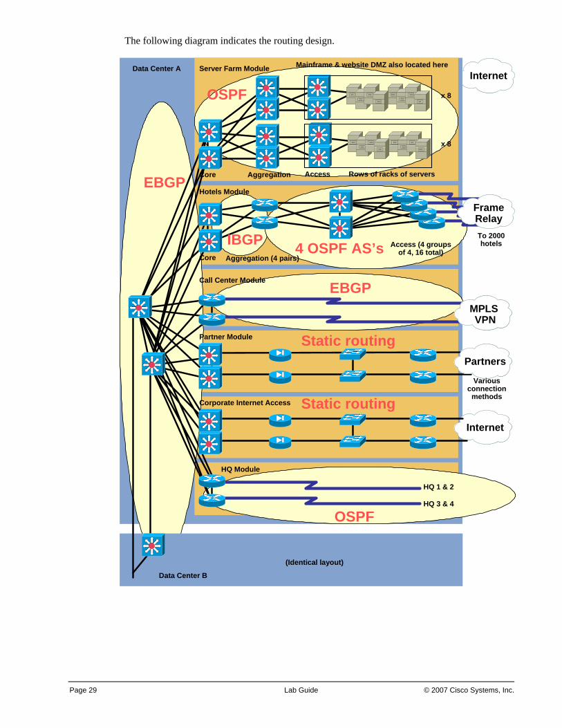
The following diagram indicates the routing design.
InternetInternet
Data Center B
Data Center A
(Identical layout)
HQ 1 & 2
HQ 3 & 4
HQ Module
Corporate Internet Access
Partner Module
Call Center Module
Hotels Module
InternetInternet
PartnersPartners
MPLS VPN
MPLS VPN
Core Aggregation (4 pairs)
Access (4 groups of 4, 16 total)
FrameRelayFrameRelayTo 2000 hotels
Various connection
methods
Core
Server Farm Module
Aggregation Access Rows of racks of servers
x 8
x 8
Mainframe & website DMZ also located here
EBGP
OSPF
EBGP
Static routing
Static routing
4 OSPF AS’sIBGP
OSPF
Page 30 WHAT IS MY NAME? (ARCH) v2.0 © 2007 Cisco Systems, Inc.
Addressing at CP Hotels
HQ buildings were addressed from the public address block 150.1.0.0 /16.
Site Address Block Total Addresses in Block Active Desktop and Access Ports
HQ1 150.1.0-31 8192 2500
HQ2 150.1.32-63 8192 2500
HQ3 150.1.64-95 8192 3000
HQ4 150.1.96-111 4096 1000
Data Center A uses some addresses from 150.1.240-255. Both data centers use addresses from 10.1.0.0 /16 and 172.20.0.0 /16. This scheme reflects different addressing schemes over time, and the difficulty of getting server staff to change addresses on servers. (“Server addresses are forever.”)
Partner addresses are public addresses chosen by the partner to avoid any possible address duplication. They come from multiple blocks per partner.
Call Centers use addresses from 180.1.0.0 /16, assigned to allow room for growth.
Concerning hotels, each Region of 500 hotels is assigned address blocks as follows:
Region Address Block Total Addresses in Block Active Desktop and Access Ports
1 10.96-103 2,097,152 Up to 128,000 (500 x 256)
2 10.104-111 2,097,152 Up to 128,000
3 10.112-119 2,097,152 Up to 128,000
4 10.120-127 2,097,152 Up to 128,000
This matches a bit mapping of 10.011r raaa.aass ssss.hhhh hhhh, where “r” indicates the region bits (region minus 1), “a” indicates the area bits within that region, “s” indicates the subnet bits relative to the area, and “h” indicates the host bits in the subnet.
Within each region, the 5 area bits allow for 32 areas (16 plus area 0 forces us up to 32, however, or 6 bits). Within each area, there are 32 or fewer hotels, which use 32 subnets. 6 subnet bits are used to allow flexibility and also provide /30 blocks for the WAN links.
Consulting Statement of Work 1
CP Hotels requires a completely new design for the hotels portion of the network (Hotels Module internals, plus WAN connections). All other connectivity will remain the same as before.
The plan is to reduce costs by using one or two Cisco ISR routers at each hotel, with one or two Internet connections from local ISPs. Hotel guests will be able to use a hotel wired and/or wireless network to access the Internet directly over the ISP link, protected by the IOS Firewall.
Page 31 Lab Guide © 2007 Cisco Systems, Inc.
The data centers will be connected to the hotels through major international ISPs. Traffic from hotels will reach the data centers across the Internet from the hotel local ISPs through various peering points.
At each hotel, the main office and front desk will be on a separate interface or VLAN protected by the IOS Firewall. CP Hotels believes the switch-let and secure wireless modules are attractive for future data connectivity within the front office. Right now IT Services does not attempt to manage LAN connectivity in hotels, local contractors provide those services, so the ISR routers will not contain such modules at least initially.
Hotel office traffic will be carried back to the data centers via IPsec VPN. A VPN to each data center will be used for redundancy.
The routing metrics on IPsec tunnels or routes to IPsec peers are to be adjusted in some fashion to provide determinism, so that half the hotels normally route via Data Center A, and half through Data Center B. The design should dynamically fail over to the other data center if the primary path becomes unavailable.
Congratulations on winning this design project! If your consulting firm does a good job on the design and documentation, you may be asked to assist in the implementation phase (full-time work for 8 consultants for at least one year, with a lot of travel). If you continue to impress the CIO, your team will get complimentary upgraded rooms and breakfast at the hotels used during the implementation. (Although the hotel chain is paying the travel expenses for the project anyway.)
Consulting Statement of Work 2
CP Hotels wants you to review their design for high-level “holistic” security. Specific questions to consider are listed below. They have already re-designed their collocated web site to use a classic three-layer DMZ implemented using FWSM and CSM or ACE modules in the switches within the collocation facility.
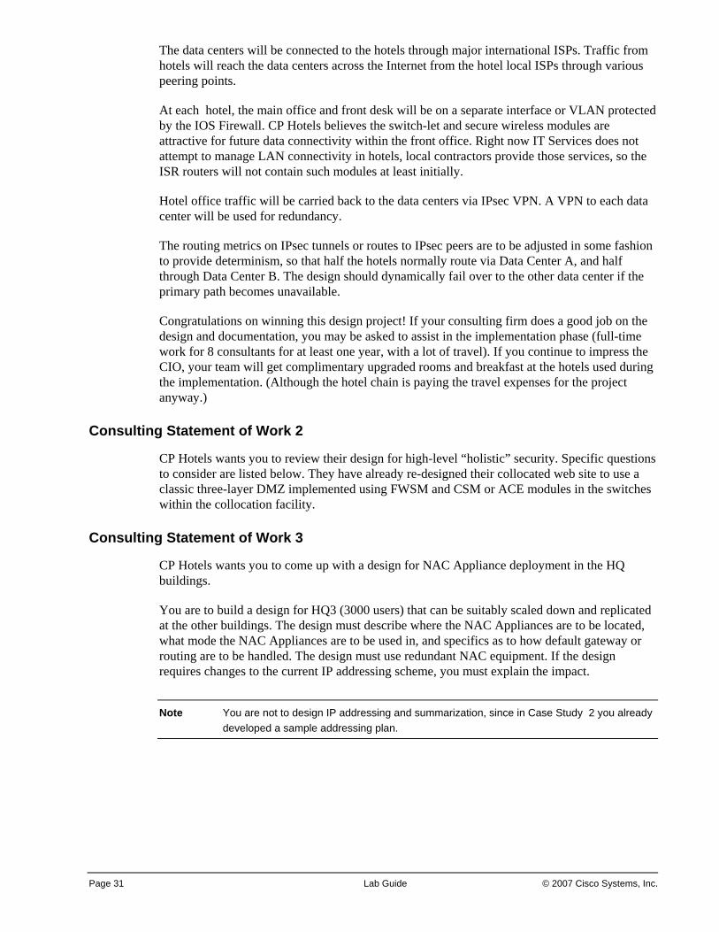
Consulting Statement of Work 3
CP Hotels wants you to come up with a design for NAC Appliance deployment in the HQ buildings.
You are to build a design for HQ3 (3000 users) that can be suitably scaled down and replicated at the other buildings. The design must describe where the NAC Appliances are to be located, what mode the NAC Appliances are to be used in, and specifics as to how default gateway or routing are to be handled. The design must use redundant NAC equipment. If the design requires changes to the current IP addressing scheme, you must explain the impact.
Note You are not to design IP addressing and summarization, since in Case Study 2 you already developed a sample addressing plan.
Page 32 WHAT IS MY NAME? (ARCH) v2.0 © 2007 Cisco Systems, Inc.
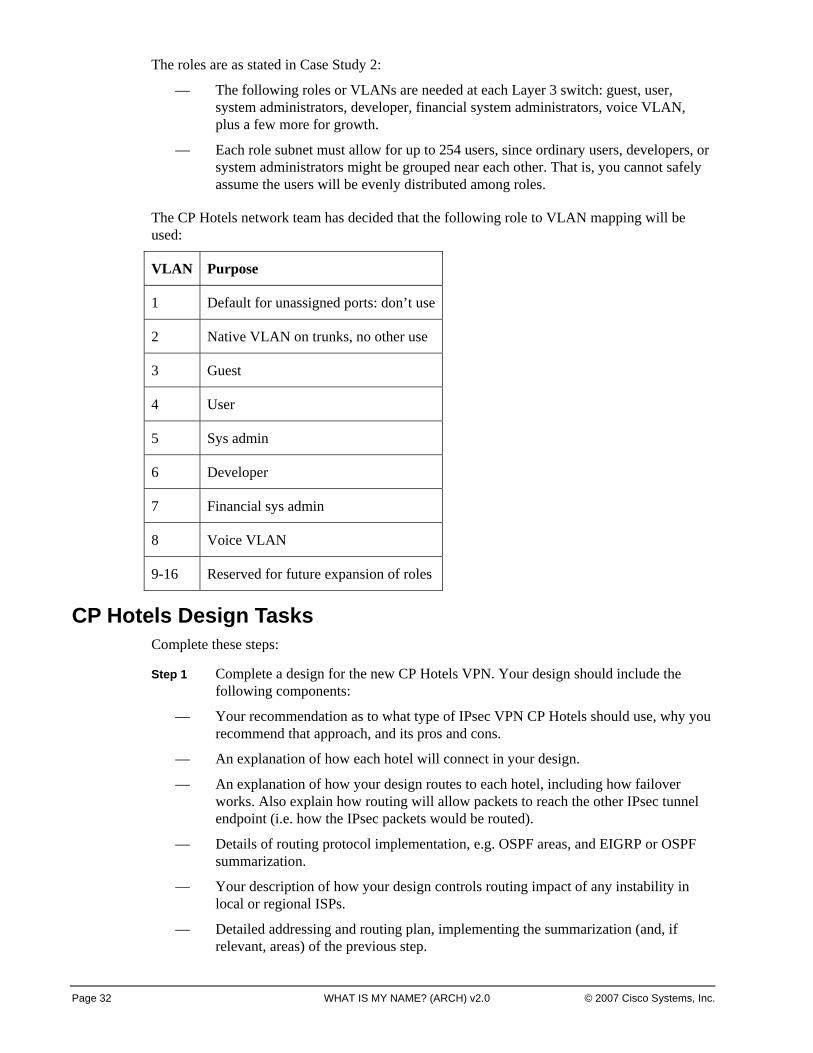
The roles are as stated in Case Study 2:
— The following roles or VLANs are needed at each Layer 3 switch: guest, user, system administrators, developer, financial system administrators, voice VLAN, plus a few more for growth.
— Each role subnet must allow for up to 254 users, since ordinary users, developers, or system administrators might be grouped near each other. That is, you cannot safely assume the users will be evenly distributed among roles.
The CP Hotels network team has decided that the following role to VLAN mapping will be used:
VLAN Purpose
1 Default for unassigned ports: don’t use
2 Native VLAN on trunks, no other use
3 Guest
4 User
5 Sys admin
6 Developer
7 Financial sys admin
8 Voice VLAN
9-16 Reserved for future expansion of roles
CP Hotels Design TasksComplete these steps:
Step 1 Complete a design for the new CP Hotels VPN. Your design should include the following components:
— Your recommendation as to what type of IPsec VPN CP Hotels should use, why you recommend that approach, and its pros and cons.
— An explanation of how each hotel will connect in your design.
— An explanation of how your design routes to each hotel, including how failover works. Also explain how routing will allow packets to reach the other IPsec tunnel endpoint (i.e. how the IPsec packets would be routed).
— Details of routing protocol implementation, e.g. OSPF areas, and EIGRP or OSPF summarization.
— Your description of how your design controls routing impact of any instability in local or regional ISPs.
— Detailed addressing and routing plan, implementing the summarization (and, if relevant, areas) of the previous step.
© 2007 Cisco Systems, Inc. Lab Guide 33
Step 2 Review the CP Hotels design concerning overall security. Your report should include at least the following:
— Your observations of any security problems in the present design. Also note ways in which packet and control plane security might be improved.
— A check that all external connections are properly secured with firewalls. (Since all the details have not been specified, indicate what you want the design to look like at each external connection.)
— Your recommendations for where CP Hotels should deploy IPS systems, and how they should be deployed, also where to deploy Cisco MARS.
— Your evaluation of the risks concerning the Call Centers, and how best to mitigate those risks. The CP Hotel.com site and the Call Centers are crucial to revenue production at CP Hotels. The collocation facility redesign secured the e-commerce site. Now it is time to ensure the Call Centers are secure.
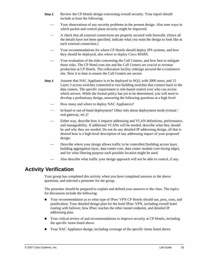
Step 3 Assume that NAC Appliance is to be deployed in HQ3, with 3000 users, and 15 Layer 3 access switches connected to two building switches that connect back to the data centers. The specific requirement is role-based control over who can access which servers. While the formal policy has yet to be determined, you will need to develop a preliminary design, answering the following questions at a high level:
— How many and where to deploy NAC Appliances?
— In-band or out-of-band deployment? Other info about deployment mode (virtual / real gateway, etc.)?
— Either way, describe how it impacts addressing and VLAN definitions, performance, and manageability. If additional VLANs will be needed, describe what they should be and why they are needed. Do not do any detailed IP addressing design, all that is desired here is a high-level description of any addressing impact of your proposed design.
— Describe where your design allows traffic to be controlled (building access layer, building aggregation layer, data center core, data center module core-facing edge), and for what filtering purpose each possible location might be used.
— Also describe what traffic your design approach will not be able to control, if any.
Activity Verification Your group has completed this activity when you have completed answers to the above questions, and selected a presenter for the group.
The presenter should be prepared to explain and defend your answers to the class. The topics for discussion include the following:
Your recommendation as to what type of IPsec VPN CP Hotels should use, pros, cons, and justification. Your detailed design plan for the hotel IPsec VPN, including overall hotel routing with failover, how IPsec reaches the other tunnel endpoint, and detailed IP addressing plan.
Your critical review of and recommendations to improve security at CP Hotels, including the specific items listed above.
Your NAC Appliance design, including coverage of the specific items listed above.

34 Designing Cisco Network Service Architectures (ARCH) v2.0 © 2007 Cisco Systems, Inc.
© 2007 Cisco Systems, Inc. Lab Guide 35
Case Study 5: DS Medical Research Institute Network Infrastructure
This case study enables you to practice the skills and knowledge learned in the modules up to this point, especially “IPsec and SSL VPN Design”, “IP Multicast Design”, “Voice Over WLAN Design”, and “Network Management Capabilities with Cisco IOS Software” modules. It is intended as a cumulative case study to bring together the concepts you have learned in this course.
This Case Study is based on a fictional organization funded by a large trust fund established by an extremely wealthy donor with initials DS. The DS Medical Research Institute (“DS-MRI”) is trying to speed medical progress with cutting edge research towards cures for several targeted major medical problems. The staff of DS-MRI conducts pharmaceutical, biochemistry, and computer-driven research, and also acts as a clearinghouse for data on cases and drug trials from around the world.
You represent a Cisco Partner that was invited to design a network for DS-MRI. The first building for the new Headquarters and Research Campus is already under construction. The Institute Director wants to design and pre-stage the network so that researchers can be up and running as soon as possible.
What is needed now is a high-level design, where you propose a general approach. If the Institute Director likes your work, your company may be asked to develop the detailed design, order the equipment, and do the pre-staging and installation work.
Activity Objective In this activity, you will design the network for DS-MRI.
After completing this activity, you will be able to meet these objectives:
Prepare and present a high-level building and data center design for DS-MRI
Prepare and present high-level alternative to add security
Design and justify how to extend the design to include more buildings
Propose a suitable high-level routing design
Prepare and present a high-level SAN design for the scenario
Propose a design or technology for grouped servers with substantial inter-server communications
Prepare and present a WAN design meeting the specified requirements
Propose and defend an IP multicast design
Prepare and present a high-level wireless design supporting VoWLAN and the Cisco Location Appliance
Prepare and present a design for using Cisco IOS network management features to meet the customer need, along with describing where those features will be used
Visual Objective There is no visual objective for this case study.
36 Designing Cisco Network Service Architectures (ARCH) v2.0 © 2007 Cisco Systems, Inc.
Required Resources These are the resources and equipment required to complete this activity:
Case Study guidelines, presented in the Course Introduction
The scenario below
A workgroup consisting of two to four students
Blank sheets of paper and a pencil
DS-MRI Case Study Scenario The first building will be completed in a few months. More buildings are planned for the campus but are not yet funded or designed.
The Building 1 of the planned campus consists of five interconnected wings, each of which has 6 floors. There will also be a large attached data center connected to the back of the building by elevated walkways providing views of the beautiful hillside campus setting.
The wings are named A, B, C, D, and E. They mingle office space, bio/chem/medical lab space, and computer researcher spaces. The spaces are intended for somewhat flexible use as projects and initiatives start and end, and as needs changes.
Each floor of each wing is about 20,000 square feet, housing up to 200 staff, with four network ports planned per 100 square feet, for a total of 800 ports per floor. All ports will be wired for Gigabit Ethernet. Uplinks are to be at least 10 Gbps.
The medical researchers’ time is precious. The promise of copious computing and network support was made to help recruit key research talent. Some of the researchers use medical imaging of cancer or other patients, reviewing high resolution CAT, DS-MRI and other scan “movie” files that can be 10 GB or larger in size. The computer research tends to be compute-intensive (gene database lookup or correlation, molecular modeling, etc.). Some of the computer research leads to computer-animated images, but at much lower resolution than the medical imaging. Researchers working with outside researchers or clinical trials sometimes receive DVDs with data and need to load these into the appropriate server(s) for statistical or other analysis.
The data center will host a large number of servers. Some will provide file, print, and directory services for staff. Others will provide research database or compute cluster capabilities. The plan is to have the data center network provide flexible hosting, to allow server hardware to be shifted between projects. Highly compute-intensive projects may use special hardware appropriate for the type of computation being done. Longer-running computations will require an appropriate degree of data center High Availability so as not to lose days or weeks of computation.
The plan is for the data center to start with 2000 servers, probably mostly blade servers. Each will have two Gigabit Ethernet connections to the network. That number may well grow to 6000 or more servers, as more projects and then more buildings are added.
There will also be 200 file or database servers providing access to large medical images. These are to be connected with either multi-Gigabit EtherChannel or 10 Gbps Ethernet connections.
© 2007 Cisco Systems, Inc. Lab Guide 37
DS-MRI Design TasksComplete these steps:
Step 1 Complete a high-level design for the Building 1 and the data center infrastructures.
— The Institute Director wants to know how much bandwidth the various parts of your design will supply, and what switch models you have in mind. Some approximate port counting would be a good idea.
— You should describe how they would be organized, both for Building 1 and for the data center, as well as how they interconnect.
Note At the time of this writing, the 6500 models can hold up to 8 blades with eight 10-Gbps ports each, for a total of sixty-four 10-Gbps ports. The 3750-E and 3560-E models come with two 10-Gbps uplink ports. The 3750-E may be put into stacks of up to 9 switches. Both come with either 24 or 48 10/100/1000 Mbps port models, either with or without PoE. They allow use of the TwinGig converter, for 2 Gbps SFP ports initially, then one 10 Gbps ports later.
Step 2 Design to address security concerns. Research activity needs to be secured by project. Every attempt will be made to put project team members close to one another, but that sometimes is not possible.
— The DS-MRI is mostly concerned about restricting access to servers based on project. How will your plan accommodate this?
— Suppose there is concern about protection of Intellectual Property, since any patents that come from research could be worth millions of dollars. Does that change your design? If so, how?
Step 3 Plan for growth. Your design needs to include a description of how you would expand coverage to 3 more similar buildings located 200-300 yards from each other, in a loop around the lake in the middle of the campus.
Step 4 Describe your proposed routing architecture at a high level. Detailed address planning is not needed at this time, but you should describe information such as where you would summarize routes, and what routing protocol(s) you would use.
Step 5 Discuss storage support. The current plans call for starting with 2000 blade servers, later expanding to 6000 or more. Provide a high-level SAN design to support these data center blade servers and expansion.
Step 6 Discuss server approach. The Institute Director asked a specific question: some of the computing requires many grouped servers with substantial amounts of inter-server communication. Is there any way to improve performance for these servers? Cost-effective 10 Gbps connectivity for servers is another related concern.
Step 7 Discuss WAN connectivity. DS-MRI is working internationally on many vital medical projects, teaming with many local doctors, professors, and other researchers. A flexible architecture is needed to allow for very rapid addition or removal of external WAN access, with security for data about local patients, since researchers may be actively involved in the ongoing treatment of patients. The architecture must accommodate a range of media and speeds, depending on what local facilities are available.
38 Designing Cisco Network Service Architectures (ARCH) v2.0 © 2007 Cisco Systems, Inc.
— DS-MRI is willing to consider commercial shipment of pre-configured small Cisco routers, to simplify connectivity and support at remote sites containing teams of researchers. The DS-MRI views this as providing facilities for and empowering local research teams.
— It is also important that local researchers be able to interact, and send data and possibly voice traffic as directly as possible to peers, rather than sending it to the U.S. and back out, to minimize latency.
— Recommend a WAN approach that maximizes flexibility without compromising security.
Step 8 Discuss IP Multicast implications. The HQ campus will be doing IP multicast for video and audio transmission of technical seminars and training materials. Lower resolution versions could be made available to remote sites, or this material could be provided in the form of downloads from an internal web site.
— What are your recommendations, including security and other aspects of the multicast design (at a high level)?
— If DS-MRI is going to be using IP multicast, where should the RP(s) be located? Bearing in mind the topics covered in our IP multicast module, what other design features should be used by DS-MRI in their multicast design?
— Does multicast require any impact or change your solution to the WAN connectivity design question above? If so, describe the changes needed.
Step 9 Discuss VoWLAN considerations. DS-MRI intends to deploy VoWLAN in the HQ buildings, to facilitate reaching staff when they are away from their desk or lab. The DS-MRI is also considering using the Location Appliance.
— How does this impact your design? How will the wireless devices connect to your switch design?
— What are the key site survey and AP placement considerations to support this?
— Approximately how many access points , controllers, or other items will DS-MRI need to purchase to cover the first building?
— Is there any business justification for using Location Services with VoWLAN at DS-MRI?
Note As of this writing, one WCS can support up to 3000 access points managed by up to 250 controllers. A single Location Appliance can track up to 2500 wireless devices.
Step 10 Discuss network management considerations. The DS-MRI anticipates that it will need to allocate network overhead to various research projects, for internal cost accounting corresponding to the research grant focus of the organization. To help troubleshoot issues with WAN connections, the DS-MRI Network Operations Center (NOC) will need to be able to track packet loss, latency, and jitter.
— What Cisco IOS network management features should DS-MRI consider using?
— Where in the network should DS-MRI use these features?
© 2007 Cisco Systems, Inc. Lab Guide 39
Activity Verification Your group has completed this activity when you have completed answers to the above questions, and selected a presenter for the group.
The presenter should be prepared to explain and defend your answers to the class. The topics for discussion include the following:
The high-level building and data center design
The high-level alternatives to add security to the design
The design to extend the building design to include more buildings
The high-level routing design
The high-level SAN design for 2000 blade servers, and how you propose to expand it to 6000
The proposed approach for grouped servers with substantial inter-server communications
The proposed WAN approach
The proposed IP multicast design
The requested wireless design information
The proposed network management features and where they will be used

40 Designing Cisco Network Service Architectures (ARCH) v2.0 © 2007 Cisco Systems, Inc.
© 2007 Cisco Systems, Inc. Lab Guide 41
Answer Key The recommended solutions for the activities that are described in this guide appear here.
Case Study 1 Answer Key: MegaCorp Campus Design You will create a high level design for the campus portions of the MegaCorp network including the following objectives:
Document and explain the real customer requirements for this scenario.
Complete and present an optimal high-level design, including diagram, physical and logical topology descriptions, recommended switch models and alternatives, other significant details, notes on how your design will support IP Telephony, and notes on what your Power over Ethernet (PoE) recommendations are. Describe and defend the pros and cons for your optimal design, and how it improves on the existing MegaCorp design.
Describe any other technical design factors the detailed design should incorporate.
Present a high-level approach for how to smoothly migrate from the old to the new network design.
Describe how to mitigate risks in the present MegaCorp design using Cisco switches.
Complete and present a design using Metro Ethernet components as provided in this Case Study to connect to remote office buildings.
Step 1 Real Requirements If IPT and video are under consideration, the network needs to be highly available and have
plenty of bandwidth.
The stated outage rate and duration is not compatible with “high availability”. Better availability is needed.
The long hours of office use suggest productivity and frugality are important to MegaCorp. The network needs to operate 18 x 5, not just 9 x 5.
Good service is hard to provide if customer records cannot be accessed due to a network outage. The same is even more so when IPT is in use. Not answering the phone sends the wrong signal to customers. This just emphasizes that reliability and high availability are important requirements for MegaCorp.
IPT means the design should use QoS-capable switches.
The access switches need to be PoE-capable on most if not all ports. There should be little to no need for PoE on distribution and core switches.
The access switches should provide at least 100 Mbps access ports and 1 Gbps uplinks.
The design should be recommended practices compliant. This is both a requirement and something you can use as a major justification for appropriate differences from the staff design.
Unless there is an unstated good reason for it, there is no reason to tie VLANs to departments. A follow-up question should clarify this.
Simplicity and ease of troubleshooting would be good.
42 Designing Cisco Network Service Architectures (ARCH) v2.0 © 2007 Cisco Systems, Inc.
Note that using 3 instead of 2 switches for the building distribution switches is a customer solution to a perceived problem. The real requirement is higher availability. It is up to the designer to decide the best way to provide the higher availability.
The network staff needs training and skills-building. Bringing in someone with deeper technical skills might inspire staff to build skills.
Step 2 Proposed Design
Here are some points about the optimal design and how to justify it:
The current MegaCorp design is clearly an older style of design. More substantial use of Layer 3 switching would provide better stability. The problem is telling the customer that, diplomatically but effectively. Justification: Routing limits the scope of failure domains and is simpler and easier to troubleshoot.
Use VLANs per closet or portion of floor, and get out of the moves, adds, changes business. Justification: This frees up staff for more useful tasks, or cuts costs. It also helps minimize VLANs spanning distribution switches.
With 10,000 employees, 8 buildings, there will be about 1250 people per building, perhaps 250 or 300 per floor. This design assumes to start that twice that many ports are needed. To support this port density, a modular switch such as a Cisco Catalyst 4500 or 6500 Series switch is recommended.
Note An alternate design would use five or size 48 port 100/1000 switches at the access layer per closet per floor to support the expected 500 to 600 ports per floor. The Cisco Catalyst 3750 Series switches with StackWise technology would avoid daisy-chaining access layer switches as occurred in the original design. Daisy-chained switches are strongly to be avoided, due to the high likelihood of STP problems . However, this alternative with multiple individual switches should be avoided since the sheer number of devices becomes hard to manage.
You should plan for one or two VLANs per access switch. With 20:1 oversubscription estimate, and 100 MB access ports, each chassis would need an uplink of about 1.25 G so use 2 GB EtherChannel to each building switches. The VLANs should be at most triangles consisting of the two uplinks and the trunk between the distribution layer switches if needed to span distribution switches.
Layer 3 (routing) to the access layer should be considered as a desirable option. It increases cost mildly, but would greatly reduce the need to troubleshoot Spanning Tree (simplicity!). It would require some staff training for the MegaCorp technical staff.
The distribution layer could be small 6500s, and the core bigger 6500 model switches. One argument in favor of using the 6500 would be 10 Gbps readiness which can also support oversubscription ratios for data today, and voice in the future.
The current Layer 2 Core is an older approach. Most sites want Layer 3 cores to avoid the large-scale outage a core Spanning Tree loop creates. You should highly recommend MegaCorp use a Layer 3 core. A Layer 2 Core would be unwise with 8 x 2 + 2 = 18 switches in the STP domain.
The building switches should have two uplinks to the core switches, not just one. Recommended Practice: “Use triangles, not squares.” Justification: Equal-cost routing provides fast failover. If you use 4:1 oversubscription model, the uplinks from building to core would be (2 closets * 2 GB * 5 floors)/4 = 5GB. So the design can start with 4 GB
© 2007 Cisco Systems, Inc. Lab Guide 43
uplinks, since the speeds on the uplinks from closets were rounded up. All uplinks in the design will need to be upgraded when VoIP is deployed.
Simplicity is somewhat at odds with power injection. PoE is affordable for MegaCorp if used where needed, namely in the access switches. While utility ports (printers, etc.) might be grouped on one non-PoE blade, it may be simpler to just provide PoE support on any port or blade in an access switch.
The distribution and core switches need little or no PoE.
VTP transparent mode is required: there is little reason for VLANs to be changing frequently.
Step 3 Other Technical Design Elements Turning off STP anywhere should be avoided.
Layer 2 and Layer 3 security features should be used (disable trunking on access ports, set native VLANs to an unused VLAN for trunks, BPDU Guard, Root Guard, Dynamic ARP Inspection, …).
Any Layer 2 switches should use the Layer 2 toolkit (UplinkFast, UDLD, etc.).
Use voice VLANs in every closet.
(Later topic) Plan addressing to assist in IPT deployment, and allow simple access lists for quality of Service (QoS) and voice security.
Coming up with a QoS architecture (plan) would be a good follow-up task.
Note Congratulations! MegaCorp agrees to your proposal. They especially liked the part about including design and implementation services in with the three year equipment lease.
Step 4 Network Migration Plan Put in the replacement core switches next to the existing ones. Cable them, and route
between old and new networks. This is simplified if a distinct address block or prefix is used for the new switches.
Put in the replacement building switches next to the existing one. Cable their uplinks to the core. Configure routing, etc.
Schedule building cutover to occur during the night (one building per week allows time for preparation, recovery from a late evening, etc.). When cutting over an existing building, pre-position and configure closet switches. First test link status and cable or fiber quality on the uplinks, then shut those ports down before configuring the switch. Pre-provision any DHCP scopes that will be needed.
The actual cutover then consists of activating uplinks, moving user patch cables, re-addressing printers and devices with hard-coded addresses, verifying DHCP is working, verifying key applications work, troubleshooting, etc.
Have a Quality Assurance plan to help make sure that everything is done properly despite late night brain fogging.
Step 5 Mitigating the MegaCorp “Equipment Modernizing” Plan Use Layer 3 Core if at all possible.
Decrease the size of VLANs to single closets if at all possible.
44 Designing Cisco Network Service Architectures (ARCH) v2.0 © 2007 Cisco Systems, Inc.
Use the Layer 2 toolkit (UplinkFast, UDLD, etc.)
Use Rapid PVST+ not regular Spanning Tree.
Tell them that a third building distribution switch will not provide them more redundancy, it will mostly provide more complexity to the solution.
Step 6 Redesign for Metro Ethernet and Acquisition The point here is that Ethernet WAN or Metro Ethernet are similar to Ethernet in the Core.
Use Layer 3 switching from each remote building back to the core. This will contain any Spanning Tree problems to the building. While it would be best if the remote building distribution layer switches did Layer 3 switching, terminating in a routed connection on the main campus core at least protects the existing campus from Spanning Tree problems to a fair degree.
The case for Layer 3 switches at remote buildings is to isolate Spanning Tree problems to one remote site. Otherwise, any Spanning Tree problem could and probably would impact all the Layer 2-connected sites on the Metro Ethernet network.
Consider the routers at each remote site. The concern is that a T1 router might well not be capable of routing between the building 100 Mbps or faster speed network and the Metro Ethernet 100 Mbps link. These routers probably need to be replaced. Given the speeds in question, and to provide some room for growth, Layer 3 switches are advisable. Whether separate switches are used, or the building switches replaced, is a choice of the customer. Replacing routers with small switches as an interim measure is quick. Replacing building switches with Layer 3 building switches might take a little longer. It makes some sense to get the new acquisition connected, then go back and revamp the building networks as needed. This is a choice for the customer to make. The designer’s role is to present the alternatives and pros and cons of each, as well as estimate the level of effort to complete implementation for each alternative, if needed.
Since the number of peers for the core switches is getting moderately large (8 x 2 + 1 = 17 before adding the remote buildings), you might consider a separate Metro Ethernet core pair of Layer 3 switches. On the other hand, adding five remote devices only bumps the number of peers to 22, which is a bit high but not terrible.
© 2007 Cisco Systems, Inc. Lab Guide 45
Case Study 2 Answer Key: CP Hotels Addressing and Routing Design
Based on the scenario, this section includes a proposed solution. According to the case study guidelines, there may be some minor variations in your solutions.
Step 1 Addressing The Call Center blocks go up by 12. Going up by 8 would summarize better and still
provide enough address space.
It would be good to have a plan for address consolidation in the Data Centers, to get servers onto one prefix per Data Center, say over a 5-7 year period as servers are replaced.
Step 2 Routing and Summarization The hotel areas should be made totally stubby. (This was not specified, and should be
brought up with the customer, recommended if not part of the present design.)
The HQ areas should also be totally stubby.
EIGRP would make the design simpler in the following ways:
— EIGRP can filter all but corporate prefix summaries or default routes from the routes sent to the hotels, greatly reducing the routing traffic to hotels. OSPF has to flood all LSAs to all hotels, plus all prefixes imported from BGP. This is exacerbated by FR instability.
— OSPF does not allow intra-area filtering, so all hotels within an areas see routes to each other, yet there is no reason for one hotel to have a route to any other hotel.
— In conjunction with filtering and corporate summaries, the EIGRP stub feature would be useful for hotels.
— The VLAN links between Data Centers would not be needed for area contiguity and avoiding having OSPF transit traffic going through hotel sites to stay within an area. They still would be needed due to the route summarization, however. (Why?)
EIGRP could be useful in the Server Farm Module, for more flexibility, although OSPF should work reasonably well there, given the regularity of the topology. OSPF has the virtue that it can be used with Cisco FWSM or PIX, CSS/CSM Route Health Injection, etc., whereas EIGRP cannot.
The OSPF aggregation routers could be done away with, but the price would be a much larger (and single) area 0, more routes being sent to hotels, and a lot of peers for the core-facing EBGP routers. The present design compartmentalizes the large-scale hotel routing well.
NAT for partners would avoid the injection of random prefixes into core BGP, also would allow partners to use private addresses without concern about overlapping server addresses at CP Hotels that they need to communicate with.
BGP route reflector won’t help with EBGP. It might be used for the IBGP in the Hotels Module, although the same peering would be needed (each aggregation router peered to both core-facing routers). Not using Route Reflector has the advantage that one hotel aggregation block (Region) doesn’t need to see routes to the others anyway.
The links to twin routers are needed to prevent black-holing packets if a hotel link fails. Otherwise, the summary prefix advertisement may draw in packets to the router with the
46 Designing Cisco Network Service Architectures (ARCH) v2.0 © 2007 Cisco Systems, Inc.
failed link, and it would have no good way to get them to its twin in the other Data Center with a good link to the hotel. The same might happen with EIGRP summarization.
There is no failover to Partners. Careful import of routes via BGP and BGP peering through the firewalls is one option. Another would be redistribution into OSPF and passing OSPF to the firewalls and the core-facing routers. Network statements could then advertise the Partner prefixes into the EBGP.
The answer for Corporate Internet failover is to use EBGP to the ISPs or some other method (see the later Data Center module) to track connectivity. And then pass default back into the core. Static default routing is unsatisfactory for failover.
Step 3 Redistribution and Default Routing It would be better to use network statements to selectively inject routes into EBGP. This
would mitigate the risk of having a problem with excess or incorrect routes in one Module spilling over into the core. (Tradeoff: maintenance that control requires versus increased stability).
If the Partner Module connected into the Corporate Internet Module’s core-facing routers, then traffic to a Partner could follow default, say from a server to the Internet core-facing router, which would then have a more-specific route to the Partner.
For Partner failover, dynamic routing is needed. A dedicated link (VLAN) or two to the Partner Module in the other Data Center would also be needed. That way, the more specific routes would work even if a Partner link were down in one Data Center. (This is the price of summarization, viewing default routing as an extreme case of summarization.)
Step 4 NAC Addressing Scheme
Addressing for NAC roles requires some calculations. You will need a subnet per role at each Layer 3 switch. One design choice is to use 8 or 16 subnets per Layer 3 switch. It is a good practice for each HQ building to be summarizable.
Figuring that room for expansion requires 16 subnets per Layer 3 switch, we would have:
HQ Building Active Ports Number of Layer 3 switches
1 2500 13
2 2500 13
3 3000 15
4 1000 5
The information about 254-user subnets means we need a /24 for each role. Another way of saying that: the last 8 bits are host bits. They would be preceded by the 4 bits we need for 16 subnets. That gets us to xxxx xxxx.xxxx xxxx.xxxx ssss.hhhh hhhh, using “s” for subnet bits and “h” for host bits, “x” for unknown bits.
Let us use 4 bits for the Layer 3 switch. That brings us to xxxx xxxx.xxxx xxxx.rrrr ssss.hhhh hhhh, using “r” for router or Layer 3 switch.
© 2007 Cisco Systems, Inc. Lab Guide 47
Another option uses 3 bits for designating the HQ building (building in some room for growth, management always grows). Using “b” for the HQ building brings us to xxxx xxxx.xxxx xbbb.rrrr ssss.hhhh hhhh.
Assuming the addresses are available, we might then use 10.80-83 for the four buildings. Within each of those, we would use the third octet to indicate Layer 3 switch (first four bits) and role subnet relative to that switch. All subnets would be /24s, which keeps things simple.
This scheme is somewhat wasteful of address space. There are two advantages of the scheme:
1. It readily accommodates moves adds and changes of users
2. It is uniform, rather than treating four HQ buildings differently.
Step 5 Collocation of Web Servers
The simplest thing is to view the collocation site as a WAN extension of the Server Farm Module. That is why we ruled out managed services at the collocation facility, to avoid the complexity of firewalls in between the data center and the collocation facility.
One design would add a pair of routers into the Server Farm Module, connecting into the aggregation or core switches within that module. The WAN links would terminate to the collocation facility in those routers. The collocation site would run as a separate OSPF area with summarization.
If firewalls were added, routing OSPF to the firewalls is perhaps the simplest answer. There are other alternatives that are discussed later in the course.

48 Designing Cisco Network Service Architectures (ARCH) v2.0 © 2007 Cisco Systems, Inc.
© 2007 Cisco Systems, Inc. Lab Guide 49
Case Study 3 Answers: CP Hotels Network Initiatives These tasks are all intended to stimulate debate. The Server Farm and to some extent WAN tasks are somewhat open-ended, where any of several answers might be suitable. The E-Commerce module is more of a direct “interpret the slides in this context” effort, requiring thinking through how to best fit a FWSM and Content Switching Module (CSM) or Application Control Engine (ACE), or ACE alone, into a chassis to meet the requirements. The SAN design is mostly about “Is there a business case?”, the design concepts available for use without more SAN expertise are rather limited.
Step 1 E-Commerce WAN Frame relay and ATM are too slow and typically too costly to be attractive. They also do
not provide much speed flexibility. On the other hand, ATM from a quality provider that is not phasing it out (yet) might be very reliable and affordable, if they view the service as revenue from equipment that is already fully depreciated.
The connections are highly critical, so very high availability and low mean time to repair (MTTR) is also a requirement. If available at a reasonable price, dark fiber, especially on one or two SONET rings, would be most attractive. The alternative would be some form of Metro Ethernet, if available. Smaller companies might favor the latter, viewing dark fiber or SONET as having associated equipment and skill costs. Larger companies might (or might not) consider Metro Ethernet a business risk. Inquiry into the underlying topology and how the Metro Ethernet service is provided could reassure management as to the risks. Unfortunately, knowing that the customer demarcation point is Gigabit Ethernet tells you nothing about the quality of and reliability of the underlying provider network.
One factor not specified is how robust the applications in the E-Commerce collocation facility are. Does a little WAN hiccup cause say 20-30 minutes of slow web response to customers? Or can the WAN be down for 3-5 minutes and applications pick right up where they left off? Can reservations be booked via some local storage if the data center and mainframes are unavailable? This information helps to evaluate business risk. However, even if this information is available, the information may not be valid, since most sites just do not have the time to conduct intensive testing to understand E-Commerce complex failure modes. It is bad enough getting the next build tested for functionality and into production on time.
There are several options for the WAN service. A service where CP Hotels pays for increments of say 10 Mbps on Fast Ethernet, or 100 Mbps on a Gbps Ethernet, would be attractive for ability to “turn up the bandwidth”. Dark fiber could be viewed in the same way: use it for long haul (LH) or very long haul (VLH) Ethernet or Packet Over SONET or resilient packet ring (RPR), then shift to coarse wavelength-division multiplexing (CWDM) or dense wavelength-division multiplexing (DWDM) as more bandwidth is needed (assuming there would be no issues with wavelengths and repeaters).
In any case, you should recommend a Layer 2 service to CP Hotels, since it would be useful to run routing over the replacement WAN, to provide fast failover. Putting provider Multiprotocol Border Gateway Protocol (MBGP) in the middle of the WAN is undesirable.
You should recommend that CP Hotels start with at least 2 x DS-3 x 80% = approximately 72 Mbps, to avoid failover problems.
Note This amount of bandwidth is needed on each link.
50 Designing Cisco Network Service Architectures (ARCH) v2.0 © 2007 Cisco Systems, Inc.
To allow for another year of operation at 50% growth per year, that number should be increased to 1.5 x 72 = 108 Mbps. To allow for two years of operation at 50% growth per year, the bandwidth should be 1.5 x 108 = 162 Mbps. If the bandwidth can readily be increased, then there is no good reason to incur the costs for the second year until they are close to being necessary.
You should look for a service level agreement (SLA) with fast response time, fast MTTR, very high availability, very low packet loss, low latency and jitter. The penalties for non-compliance should be commensurate with the costs of an outage. Being able to play one provider off against another (“if your service doesn’t improve, we’ll take all our business elsewhere”) would help.
Step 2 Server Farm Refresh There is significant trade-offs in design options, between robustness driving some designers
towards “Layer 3 to the access layer”, and cost and vendor solutions such as IBM high-availability clusters (HACMP), Oracle High Availability, and VMotion pushing for “VLANs that go everywhere”. We view the latter as a substantial risk. The issue can be quite political: how well can the risk be explained to management? Can the server farm be managed so that VLANs can be contained within a row or one of the two aggregation blocks? (If not, it might be good to put your recommendations to the contrary into a diplomatic write up, and make sure the management chain sees them.) The “right answer” varies by the organization. In any case, try to limit all VLANs to one or two rows of racks, to limit per-VLAN STP domain sizes.
We recommend R-PVST+, the STP toolkit (root guard, BPDU guard, host mode on ports, VTP transparent, manually pruned VLANs, UDLD, etc. – to limit exposure to STP-related problems).
Concerning technology updates, there are several things to consider:
— tradeoffs between Sup32 or a Sup720 variants for the fabric throughput
— Implementing 10 Gbps links (core to aggregation, possibly in a year or two from aggregation to access)
— Potential need for ACE in portions of the server farm
— Out of band management of servers using multiple VLANs or via dedicated cabling and switches to localize the management STP domains
— Terminal server access to network devices? Servers?
— Planning for coordination concerning blade servers, including discussion of what type of internal switch is used (if any), who manages it, and how they do so
Concerning recommended practices, consider:
— Creating isolation VLANs or private VLANs (PVLANs) for “anti-social” servers or clusters that use multicast or unknown unicast flooding
— Using firewall service module (FWSM) in selected aggregation or access switches to isolate critical / sensitive servers (financial, credit card, or medical records)
— Adding intrusion prevention systems (IPS) for such “zones”.
— Deploying remote packet capture and analysis capability on SPAN ports near critical servers (NAM, Distributed Sniffer, laptop with WireShark and VNC, etc.). This makes staff much more productive than spending time lugging a capture device to the server farm, plugging it in, setting up a SPAN port (chance for error), and then capturing in a noisy and uncomfortable environment.
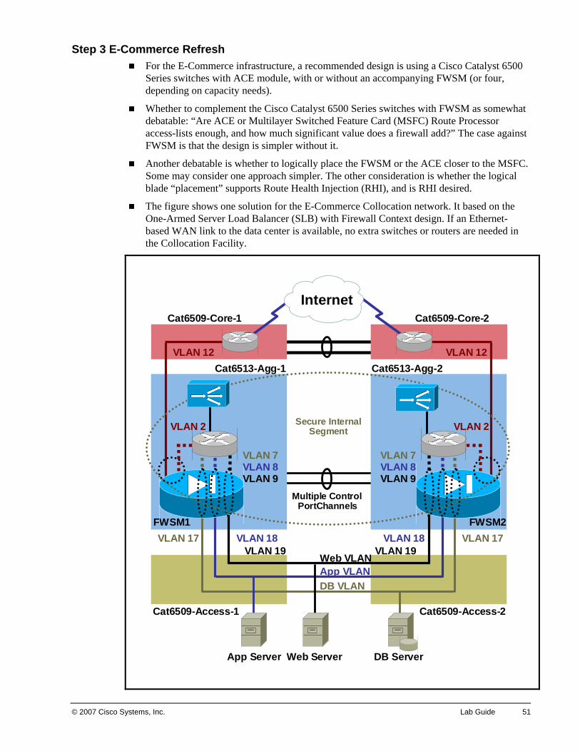
© 2007 Cisco Systems, Inc. Lab Guide 51
Step 3 E-Commerce Refresh For the E-Commerce infrastructure, a recommended design is using a Cisco Catalyst 6500
Series switches with ACE module, with or without an accompanying FWSM (or four, depending on capacity needs).
Whether to complement the Cisco Catalyst 6500 Series switches with FWSM as somewhat debatable: “Are ACE or Multilayer Switched Feature Card (MSFC) Route Processor access-lists enough, and how much significant value does a firewall add?” The case against FWSM is that the design is simpler without it.
Another debatable is whether to logically place the FWSM or the ACE closer to the MSFC. Some may consider one approach simpler. The other consideration is whether the logical blade “placement” supports Route Health Injection (RHI), and is RHI desired.
The figure shows one solution for the E-Commerce Collocation network. It based on the One-Armed Server Load Balancer (SLB) with Firewall Context design. If an Ethernet-based WAN link to the data center is available, no extra switches or routers are needed in the Collocation Facility.
InternetCat6509-Core-1 Cat6509-Core-2
Cat6513-Agg-1 Cat6513-Agg-2
Multiple ControlPortChannels
VLAN 12 VLAN 12
VLAN 17 VLAN 17VLAN 18 VLAN 18VLAN 19 VLAN 19
Cat6509-Access-1 Cat6509-Access-2
App Server Web Server DB Server
Web VLANApp VLANDB VLAN
FWSM1 FWSM2
VLAN 2 VLAN 2
VLAN 7VLAN 8VLAN 9
VLAN 7VLAN 8VLAN 9
Secure InternalSegment
52 Designing Cisco Network Service Architectures (ARCH) v2.0 © 2007 Cisco Systems, Inc.
A good alternative is to have the ACE do the routing instead of the MSFC, to simplify passing traffic between the different tiers of servers. That is, put the ACE logically between the MSFC and the FWSM, rather than the other way around.
Firewalls are needed for the data center edge, due to the specified security requirement.
One or multiple IDSM-2 modules would be attractive for IDS/IPS functionality, assuming there is room in the switch.
Note about the Infinistream deployment: did you spot the slightly subtle “SPAN port” issue? One alternative would be to use a VACL to feed each IDSM-2 module(s), also the Infinistream, since multiple VLANs or ports would need to be spanned. Another approach would be to use relatively inexpensive copper or fiber taps at key points in the cabling infrastructure.
Step 4 SAN High-Level Design One good question would be, “How many servers are there in the E-Commerce Module?”
If only a few, deploying a SAN is probably not going to help much. If many, the usual “economies of disk space” reasoning applies.
SAN might be useful for backup. On the other hand, if the servers are all clones of some base image using static or dynamically generated content, then there might be no need to back them up.
SAN might be useful for faster pushes of new builds. Coupled with VMotion, it might provide a way to bring virtual servers running a new build online rapidly, rather than having to run off a test or other production environment during the day or so to switch over to new disk content, content databases, etc.
SAN is an enabler for VMware. One approach to troubleshooting E-Commerce server problems is to just take the offending server(s) offline using the Server Load Balancer (SLB), while shifting load over to fresh virtual servers. This assumes the problem is one where the servers ran OK for a while, then got into some odd state. Instead of troubleshooting a complex problem under pressure, the new approach is to just swap the server out, and troubleshoot it offline if desired.
Our SAN design would be to estimate the relevant number of ports, allowing for some growth, preferably based on some trending data from the capacity planning group. Then put in a pair of SAN switches with enough ports. If that is not possible, then a cascaded approach would be needed.
For security, VSANs and zones could be used. Separate VSANs should be created for the web, application and db servers to keep the files for each type of server secure from the others.
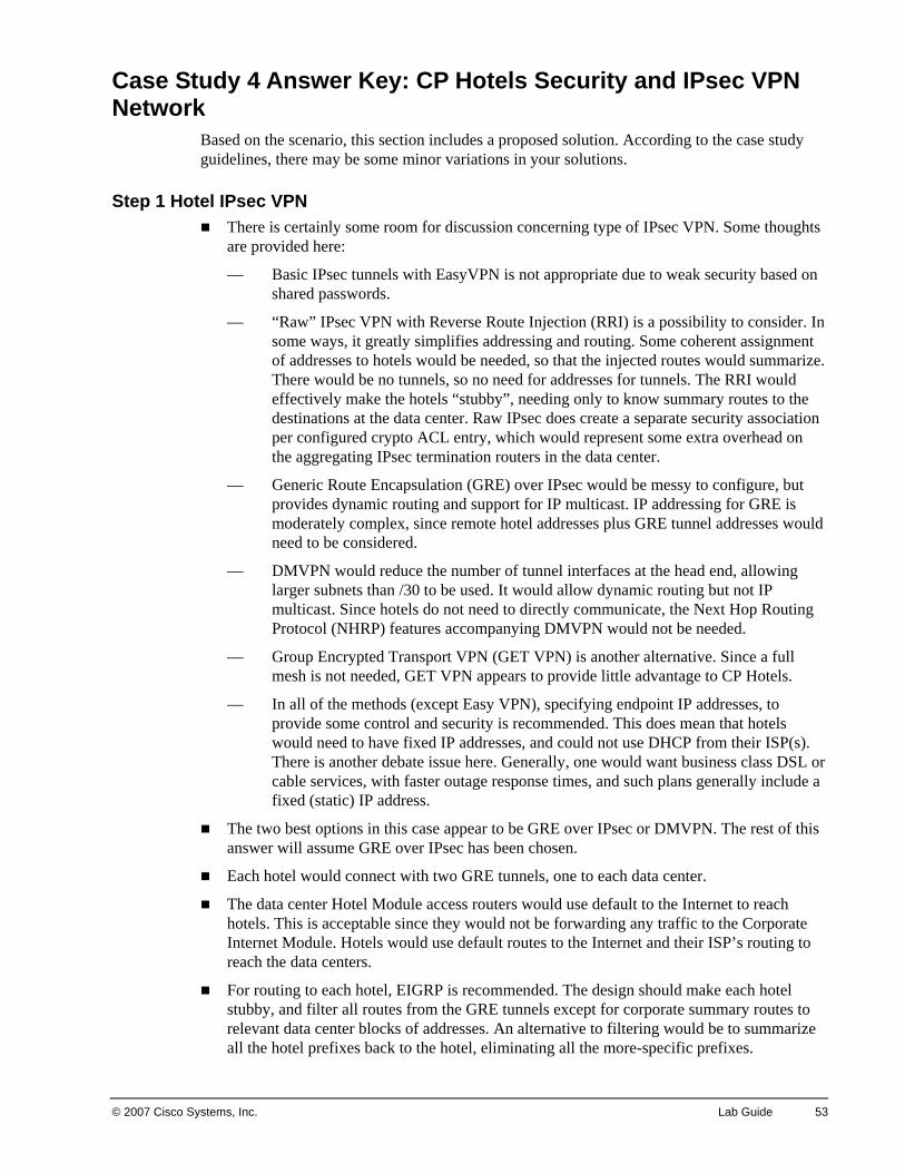
© 2007 Cisco Systems, Inc. Lab Guide 53
Case Study 4 Answer Key: CP Hotels Security and IPsec VPN Network
Based on the scenario, this section includes a proposed solution. According to the case study guidelines, there may be some minor variations in your solutions.
Step 1 Hotel IPsec VPN There is certainly some room for discussion concerning type of IPsec VPN. Some thoughts
are provided here:
— Basic IPsec tunnels with EasyVPN is not appropriate due to weak security based on shared passwords.
— “Raw” IPsec VPN with Reverse Route Injection (RRI) is a possibility to consider. In some ways, it greatly simplifies addressing and routing. Some coherent assignment of addresses to hotels would be needed, so that the injected routes would summarize. There would be no tunnels, so no need for addresses for tunnels. The RRI would effectively make the hotels “stubby”, needing only to know summary routes to the destinations at the data center. Raw IPsec does create a separate security association per configured crypto ACL entry, which would represent some extra overhead on the aggregating IPsec termination routers in the data center.
— Generic Route Encapsulation (GRE) over IPsec would be messy to configure, but provides dynamic routing and support for IP multicast. IP addressing for GRE is moderately complex, since remote hotel addresses plus GRE tunnel addresses would need to be considered.
— DMVPN would reduce the number of tunnel interfaces at the head end, allowing larger subnets than /30 to be used. It would allow dynamic routing but not IP multicast. Since hotels do not need to directly communicate, the Next Hop Routing Protocol (NHRP) features accompanying DMVPN would not be needed.
— Group Encrypted Transport VPN (GET VPN) is another alternative. Since a full mesh is not needed, GET VPN appears to provide little advantage to CP Hotels.
— In all of the methods (except Easy VPN), specifying endpoint IP addresses, to provide some control and security is recommended. This does mean that hotels would need to have fixed IP addresses, and could not use DHCP from their ISP(s). There is another debate issue here. Generally, one would want business class DSL or cable services, with faster outage response times, and such plans generally include a fixed (static) IP address.
The two best options in this case appear to be GRE over IPsec or DMVPN. The rest of this answer will assume GRE over IPsec has been chosen.
Each hotel would connect with two GRE tunnels, one to each data center.
The data center Hotel Module access routers would use default to the Internet to reach hotels. This is acceptable since they would not be forwarding any traffic to the Corporate Internet Module. Hotels would use default routes to the Internet and their ISP’s routing to reach the data centers.
For routing to each hotel, EIGRP is recommended. The design should make each hotel stubby, and filter all routes from the GRE tunnels except for corporate summary routes to relevant data center blocks of addresses. An alternative to filtering would be to summarize all the hotel prefixes back to the hotel, eliminating all the more-specific prefixes.
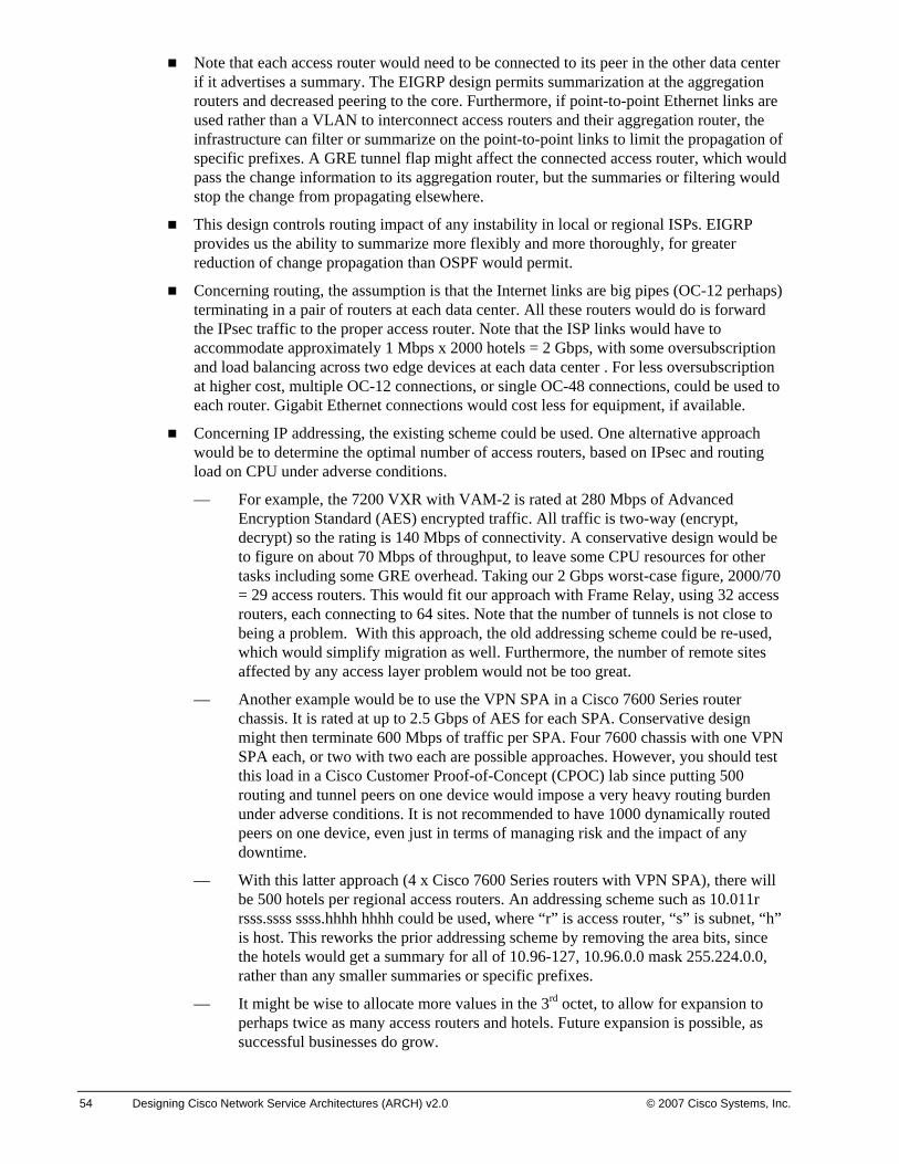
54 Designing Cisco Network Service Architectures (ARCH) v2.0 © 2007 Cisco Systems, Inc.
Note that each access router would need to be connected to its peer in the other data center if it advertises a summary. The EIGRP design permits summarization at the aggregation routers and decreased peering to the core. Furthermore, if point-to-point Ethernet links are used rather than a VLAN to interconnect access routers and their aggregation router, the infrastructure can filter or summarize on the point-to-point links to limit the propagation of specific prefixes. A GRE tunnel flap might affect the connected access router, which would pass the change information to its aggregation router, but the summaries or filtering would stop the change from propagating elsewhere.
This design controls routing impact of any instability in local or regional ISPs. EIGRP provides us the ability to summarize more flexibly and more thoroughly, for greater reduction of change propagation than OSPF would permit.
Concerning routing, the assumption is that the Internet links are big pipes (OC-12 perhaps) terminating in a pair of routers at each data center. All these routers would do is forward the IPsec traffic to the proper access router. Note that the ISP links would have to accommodate approximately 1 Mbps x 2000 hotels = 2 Gbps, with some oversubscription and load balancing across two edge devices at each data center . For less oversubscription at higher cost, multiple OC-12 connections, or single OC-48 connections, could be used to each router. Gigabit Ethernet connections would cost less for equipment, if available.
Concerning IP addressing, the existing scheme could be used. One alternative approach would be to determine the optimal number of access routers, based on IPsec and routing load on CPU under adverse conditions.
— For example, the 7200 VXR with VAM-2 is rated at 280 Mbps of Advanced Encryption Standard (AES) encrypted traffic. All traffic is two-way (encrypt, decrypt) so the rating is 140 Mbps of connectivity. A conservative design would be to figure on about 70 Mbps of throughput, to leave some CPU resources for other tasks including some GRE overhead. Taking our 2 Gbps worst-case figure, 2000/70 = 29 access routers. This would fit our approach with Frame Relay, using 32 access routers, each connecting to 64 sites. Note that the number of tunnels is not close to being a problem. With this approach, the old addressing scheme could be re-used, which would simplify migration as well. Furthermore, the number of remote sites affected by any access layer problem would not be too great.
— Another example would be to use the VPN SPA in a Cisco 7600 Series router chassis. It is rated at up to 2.5 Gbps of AES for each SPA. Conservative design might then terminate 600 Mbps of traffic per SPA. Four 7600 chassis with one VPN SPA each, or two with two each are possible approaches. However, you should test this load in a Cisco Customer Proof-of-Concept (CPOC) lab since putting 500 routing and tunnel peers on one device would impose a very heavy routing burden under adverse conditions. It is not recommended to have 1000 dynamically routed peers on one device, even just in terms of managing risk and the impact of any downtime.
— With this latter approach (4 x Cisco 7600 Series routers with VPN SPA), there will be 500 hotels per regional access routers. An addressing scheme such as 10.011r rsss.ssss ssss.hhhh hhhh could be used, where “r” is access router, “s” is subnet, “h” is host. This reworks the prior addressing scheme by removing the area bits, since the hotels would get a summary for all of 10.96-127, 10.96.0.0 mask 255.224.0.0, rather than any smaller summaries or specific prefixes.
— It might be wise to allocate more values in the 3rd octet, to allow for expansion to perhaps twice as many access routers and hotels. Future expansion is possible, as successful businesses do grow.
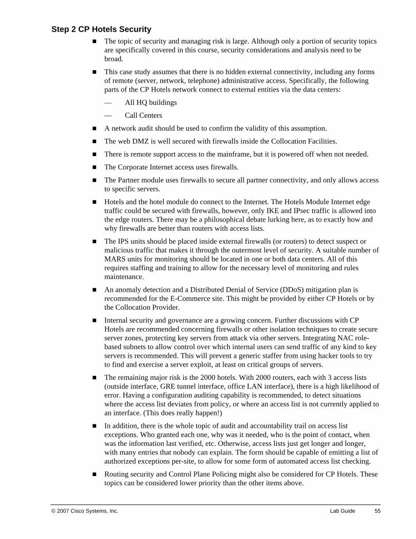
© 2007 Cisco Systems, Inc. Lab Guide 55
Step 2 CP Hotels Security The topic of security and managing risk is large. Although only a portion of security topics
are specifically covered in this course, security considerations and analysis need to be broad.
This case study assumes that there is no hidden external connectivity, including any forms of remote (server, network, telephone) administrative access. Specifically, the following parts of the CP Hotels network connect to external entities via the data centers:
— All HQ buildings
— Call Centers
A network audit should be used to confirm the validity of this assumption.
The web DMZ is well secured with firewalls inside the Collocation Facilities.
There is remote support access to the mainframe, but it is powered off when not needed.
The Corporate Internet access uses firewalls.
The Partner module uses firewalls to secure all partner connectivity, and only allows access to specific servers.
Hotels and the hotel module do connect to the Internet. The Hotels Module Internet edge traffic could be secured with firewalls, however, only IKE and IPsec traffic is allowed into the edge routers. There may be a philosophical debate lurking here, as to exactly how and why firewalls are better than routers with access lists.
The IPS units should be placed inside external firewalls (or routers) to detect suspect or malicious traffic that makes it through the outermost level of security. A suitable number of MARS units for monitoring should be located in one or both data centers. All of this requires staffing and training to allow for the necessary level of monitoring and rules maintenance.
An anomaly detection and a Distributed Denial of Service (DDoS) mitigation plan is recommended for the E-Commerce site. This might be provided by either CP Hotels or by the Collocation Provider.
Internal security and governance are a growing concern. Further discussions with CP Hotels are recommended concerning firewalls or other isolation techniques to create secure server zones, protecting key servers from attack via other servers. Integrating NAC role-based subnets to allow control over which internal users can send traffic of any kind to key servers is recommended. This will prevent a generic staffer from using hacker tools to try to find and exercise a server exploit, at least on critical groups of servers.
The remaining major risk is the 2000 hotels. With 2000 routers, each with 3 access lists (outside interface, GRE tunnel interface, office LAN interface), there is a high likelihood of error. Having a configuration auditing capability is recommended, to detect situations where the access list deviates from policy, or where an access list is not currently applied to an interface. (This does really happen!)
In addition, there is the whole topic of audit and accountability trail on access list exceptions. Who granted each one, why was it needed, who is the point of contact, when was the information last verified, etc. Otherwise, access lists just get longer and longer, with many entries that nobody can explain. The form should be capable of emitting a list of authorized exceptions per-site, to allow for some form of automated access list checking.
Routing security and Control Plane Policing might also be considered for CP Hotels. These topics can be considered lower priority than the other items above.

56 Designing Cisco Network Service Architectures (ARCH) v2.0 © 2007 Cisco Systems, Inc.
Concerning the Call Centers, there is the separate consideration of voice security, e.g. preventing outsiders from placing international calls, etc. In addition, if IP Telephony is present, the voice VLANs and Cisco Unified Call Managers should be secured and protected from the data parts of the network. Access lists and QoS are the tools for mitigating internal VoIP / IPT security risks.
Note This is a brief treatment of security considerations. In a production environment, more attention should be applied to the Call Center security. Similar real world consulting work might lead to 50 pages of specifics as well as the general principles listed above.
Step 3 NAC Appliance Design Using the heuristic of one NAC Appliance per 1500 users, two NAC Appliances are
needed. Four NAC Appliances are needed for redundancy. In addition, two Clean Access Managers are needed to cover all sites, unless standalone site capability is desired.
Layer 3 out-of-band deployment is recommended. Although Policy Based Routing (PBR) is often viewed as complex, it does allow gradual phase-in of the NAC functionality. It also allows scaling by adding more NAC Appliances, and by allowing selected traffic to bypass the NAC Appliances.
The NAC Appliances would be connected to the combined core/aggregation (building) switch pair. Due to the Layer 3 access layer switches, PBR is needed to steer quarantine VLAN traffic into the NAC Appliances for users whose posture has not yet been validated.
There is no need at this site to isolate different groups of users, which conceivably might require access layer placement of the NAC Appliances. Having one NAC Appliance per access switch gets rather costly.
All VLANs would be routed at the access layer. Only the initial quarantine VLAN would need to be policy routed through the NAC Appliance. Once a desktop computer posture was validated, its switch port would be changed to the appropriate VLAN, bypassing the NAC Appliance.
An alternative to PBR would be to have a quarantine VLAN spanning all access switches and the distribution switches. A VLAN spanning the building might be rather hazardous to your building network’s health, and is not recommended.
Traffic could be controlled with inbound access lists on the VLAN interfaces, where appropriate. Alternatively, it could be controlled elsewhere, e.g. at the data center HQ Module routers, or at the data center core-facing Server Farm Module switches.
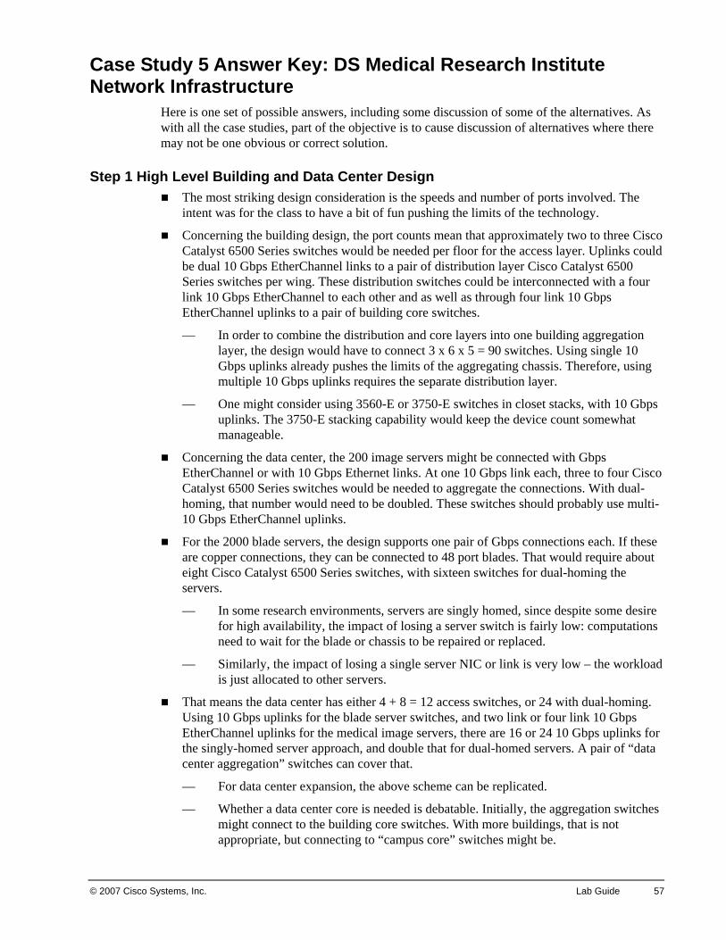
© 2007 Cisco Systems, Inc. Lab Guide 57
Case Study 5 Answer Key: DS Medical Research Institute Network Infrastructure
Here is one set of possible answers, including some discussion of some of the alternatives. As with all the case studies, part of the objective is to cause discussion of alternatives where there may not be one obvious or correct solution.
Step 1 High Level Building and Data Center Design The most striking design consideration is the speeds and number of ports involved. The
intent was for the class to have a bit of fun pushing the limits of the technology.
Concerning the building design, the port counts mean that approximately two to three Cisco Catalyst 6500 Series switches would be needed per floor for the access layer. Uplinks could be dual 10 Gbps EtherChannel links to a pair of distribution layer Cisco Catalyst 6500 Series switches per wing. These distribution switches could be interconnected with a four link 10 Gbps EtherChannel to each other and as well as through four link 10 Gbps EtherChannel uplinks to a pair of building core switches.
— In order to combine the distribution and core layers into one building aggregation layer, the design would have to connect 3 x 6 x 5 = 90 switches. Using single 10 Gbps uplinks already pushes the limits of the aggregating chassis. Therefore, using multiple 10 Gbps uplinks requires the separate distribution layer.
— One might consider using 3560-E or 3750-E switches in closet stacks, with 10 Gbps uplinks. The 3750-E stacking capability would keep the device count somewhat manageable.
Concerning the data center, the 200 image servers might be connected with Gbps EtherChannel or with 10 Gbps Ethernet links. At one 10 Gbps link each, three to four Cisco Catalyst 6500 Series switches would be needed to aggregate the connections. With dual-homing, that number would need to be doubled. These switches should probably use multi-10 Gbps EtherChannel uplinks.
For the 2000 blade servers, the design supports one pair of Gbps connections each. If these are copper connections, they can be connected to 48 port blades. That would require about eight Cisco Catalyst 6500 Series switches, with sixteen switches for dual-homing the servers.
— In some research environments, servers are singly homed, since despite some desire for high availability, the impact of losing a server switch is fairly low: computations need to wait for the blade or chassis to be repaired or replaced.
— Similarly, the impact of losing a single server NIC or link is very low – the workload is just allocated to other servers.
That means the data center has either 4 + 8 = 12 access switches, or 24 with dual-homing. Using 10 Gbps uplinks for the blade server switches, and two link or four link 10 Gbps EtherChannel uplinks for the medical image servers, there are 16 or 24 10 Gbps uplinks for the singly-homed server approach, and double that for dual-homed servers. A pair of “data center aggregation” switches can cover that.
— For data center expansion, the above scheme can be replicated.
— Whether a data center core is needed is debatable. Initially, the aggregation switches might connect to the building core switches. With more buildings, that is not appropriate, but connecting to “campus core” switches might be.
58 Designing Cisco Network Service Architectures (ARCH) v2.0 © 2007 Cisco Systems, Inc.
— It is open to debate which switches are Layer 2 and which are Layer 3, per the Campus module. The buildings might have Layer 3 at the access layer, and the data center might be Layer 2 at the access layer.
Step 2 LAN Security Design Restricting server access might just mean limiting logins to servers. If what is meant is
limiting the ability to send any packets to certain servers, then NAC is the answer. Given the speeds involved, it would have to be Out-of-Band NAC Appliance or NAC Framework, to avoid creation of a 1 Gbps bottleneck. There is insufficient information provided to determine which of the two would be a better fit for this customer.
— In the initial scenario description. NAC might be used to assign users role-based VLANs or subnets. Access lists on switches in the data center could then control which role subnets could reach which servers. The access lists might be placed on the Layer 3 switches nearest the servers. FWSM or ACE modules might also be used. There are designs available for using an ACE to split load across four ACE modules. Given the size of the connections, throughput is a major issue here.
— If the requirement is to secure different user populations from each other, one could use VLANs and access lists. This is difficult to implement and may affect network stability and manageability unless the VLANs are rather localized. As above, either Out of Band NAC Appliance or NAC Framework is a viable alternative. Using either would allow the use of role-based access lists at the first Layer 3 reached by user traffic. These access lists would have to be applied inbound (or outbound) on every user VLAN. The maintenance burden of doing this is another factor to consider.
Step 3 Design Extensions To connect other buildings in the future, there is a choice of technologies, with arguments
for each.
— One might use 10 Gbps links (one or several) in a Layer 3 ring between building core switch pairs. The max distance is 80 km, so distance will not be a problem in the campus. The 10 Gbps Layer 3 ring is not bad as long as the ring has at most four to six buildings in it. For more buildings, multiple rings could be used – it is a new campus, so it should be relatively inexpensive to put a lot of fiber in place.
— RPR or SONET could be used. The main challenge with that approach is justifying the extra layer of equipment and the extra skills that would be required to support it.
— Yet another alternative would be to start using DWDM equipment. The counter-argument is that DWDM is generally used where fiber count is low. In this case it might cost less to just put many fiber pairs in place. Many fiber pairs would also be simpler to manage.
Step 4 High Level Routing Design Use EIGRP or OSPF, with summarization at building boundaries, possibly even at wing
boundaries. If NAC role subnets are used in a design with Layer 3 closets, there will be a very large number of subnets, so summarization will definitely be needed.
— If OSPF is used, one then has the question of using BGP in the core to add another layer of summarization. The relatively slow convergence of BGP is a strong disadvantage to doing so.
— OSPF timers could be tweaked, or other features used, to enhance convergence speed, per the “Advanced Addressing and Routing Design” module.
© 2007 Cisco Systems, Inc. Lab Guide 59
Step 5 High Level Storage Design The simplest answer is to use the large scale dual fabric core-edge design shown in the
“Design Considerations for Storage Area Networks” module for 2000 servers, and use more copies of that for additional groupings of 2000 servers.
— One would have to work further with the customer to understand whether that is a valid grouping, or whether the servers should be logically broken into smaller groups with different SAN storage and administration.
— One would also need to understand whether three separate SAN fabrics would work for the customer, in terms of future use.
Step 6 Servers Approach Infiniband might be considered for some of the server groupings, or to lower costs and
offload processing for 10 Gbps server connections (for servers with intense data rates).
Step 7 WAN Design IPsec using DMVPN appears to be the best fit to the requirements described in the case
study. Internet connections are generally the fastest way to get a remote site online. DMVPN would then allow local sites to establish direct connections on an ad hoc basis in response to temporary needs, without administrative intervention.
Step 8 IP Multicast Design The campus should use PIM-SM with Anycast RP and some access controls to limit any
rogue IP multicast. The RPs should probably be located centrally, in the core or distribution layers, for efficient traffic flows.
— A good IP multicast assignment scheme should be used, with addresses from the 239.0.0.0 /8 block, in accord with the Cisco IP multicast addressing guide.
— Multicast boundaries should be used to keep multicast off the IPsec WAN, since DMVPN cannot handle IP multicast. Alternatively, if IP multicast on the WAN is a requirement, then GET VPN might be considered.
— Multicast is also not appropriate for the data center, except perhaps for the servers or video units that are sources of the multicast traffic. Application multicast, including clusters, load balancing, etc., is best when contained within a VLAN and not multicast routed. Not enabling PIM on such VLAN interfaces is one simple way to keep such multicast localized.
— In a setting like this, WAN bandwidth requirements are likely to vary widely. One answer might be to use GET VPN for sites with sufficient bandwidth, and use Video On Demand or a “push” approach to distribute content (Although not in the scope of this case study, the Cisco Application and Content Networking System (ACNS) or Cisco Wide-Area Application Services (WAAS) products are “push” approaches to distribute content.).
— Cluster or grid computing often uses multicast to distribute computational tasks to servers. Part of design might be determining policy on where such servers would be located in the data center. One could then enable multicast in a limited fashion if the number of servers suggests distributing them across switches and across multiple VLAN. Keeping inter-server traffic localized to just part of the data center would be a good idea. As the number of servers increases, this may be difficult to do, unless sufficient rack space was reserved for expansion.
60 Designing Cisco Network Service Architectures (ARCH) v2.0 © 2007 Cisco Systems, Inc.
Step 9 High Level VoWLAN Design The main impact is on the wireless site survey and access point placement. Using LWAPP
and controllers keeps the impact on the design minimal: controllers would probably be attached to wing or building switches, depending on how many are needed.
— The Location Appliance requirement suggests placing access point s in corners and on building edges, using directional antennas. Internal access point s could then be added as needed to achieve the appropriate cell sizes and access point densities to support Location triangulation and VoWLAN coverage. Since edge and corner access point s only cover ¼ or ½ a circle, they add to the access point count.
— Using the 3000 square foot per access point figure for a first approximation to the number of access point s, then each wing floor would require 20,000 / 3,000 = 7 access point s, or more. The 200 users would thus be divided into up to 30 per access point. If they all need to use wireless simultaneously, you would need to deploy additional collocated access points on different channels.
— If one knows the floor dimensions, say 100 feet by 200 feet, one can then do a little more careful estimation and initial access point placement. This level of detail would be appropriate for a real customer, but is too time-consuming to do in this case study.
— Each wing would then need 6 x 7 = 42 access points (or more). So one approach would be to use a 50- access point controller per wing, with fallback to a spare someplace else.
— Do not forget to include WCS and Location Appliance(s) to manage the WLAN To estimate the number of Location Appliances, one needs to know what or who is being tracked.
— Location Appliance coupled with wireless phones would permit locating staff or equipment. On the other hand, tracking staff locations might raise privacy concerns.
Step 10 Network Management Design NetFlow could be used to track traffic volumes and do cost allocation. It would be best
applied inbound on interfaces in the traffic path. If most traffic will be data center to desktop, NetFlow might be used at the building or wing distribution layer. Note that this would miss some localize IP phone or desktop to desktop traffic.
IP SLA could be used to provide the desired information about the WAN. This may be of limited value for Internet connections, since there is little that can be done to improve on poor conditions.
— IP SLA would most likely be done between the remote router and central site routers.
— As the number of remote connections increases, it might be wise to offload the central IP SLA responder role to dedicated routers.
— IP SLA should not be needed within the campus or datacenter. However, some tools should be used to identify duplex or speed problems with links, and Spanning Tree or routing instability in the network, as all would cause performance problems with traffic across the campus.
© 2007 Cisco Systems, Inc. Lab Guide 61
DS-MRI would also need to identify tools that are:
— Cost-effective
— Scale to the desired scale
— Reasonably easy to manage and use
— Produce good reports with the desired information

62 Designing Cisco Network Service Architectures (ARCH) v2.0 © 2007 Cisco Systems, Inc.


