TECHNICAL NOTE On Cold-Formed Steel Construction 1201 15th Street, NW, Suite 320 W ashington, DC 20005 (202) 785-2022 $5.00 DESIGNING COLD-FORMED STEEL USING THE DIRECT STRENGTH METHOD The key documents and tools necessary for the application of the Direct Strength Method are summarized in Figure 1, they include: (a) The North American Specification for the Design of Cold-Formed Steel Structural Members (AISI- S100-07) also known as the main Specification, (b) the Direct Strength Method (DSM) Design Guide (AISI 2006), and (c) the finite strip software CUFSM (Schafer 2006). The Direct Strength Method provisions are straightforward. For example, column design was excerpted from AISI-S100- 07 and is provided in Figure 2. Complete column design takes only one page. The engineer must provide the elastic buckling loads in global (P cre ), local (P crl ), and INTRODUCTION Cold-Formed Steel Engineers Institute TECH NOTE G102-09 August 2009 1 Summary: The Direct Strength Method is an entirely new design method for cold-formed steel. The Direct Strength Method requires no effective width calculations, eliminates tedious iterations to determine section properties, properly includes interaction effects between elements of the cross-section such as the flange and the web, and opens up the potential to create new sections as it is applicable to nearly any shape that can be formed from cold-formed steel, as opposed to just C, Z and hat shapes. The Direct Strength Method was first adopted in 2004 as Appendix 1 to the North American Specification for the Design of Cold-Formed Steel Structural Members, and the most recent version can be found in the recently published AISI-S100-07. This CFSEI Technical Note introduces the Direct Strength Method and details some of the features of a recently published AISI Design Guide for this Method. The intent of this Tech Note and the Guide is to provide engineers with practical guidance in the application of this new design method. Disclaimer: Designs cited herein are not intended to preclude the use of other materials, assemblies, structures or designs when these other designs and materials demonstrate equivalent performance for the intended use; CFSEI documents are not intended to exclude the use and implementation of any other design or construction technique. (a) Specification AISI (2007) 1 (b) DSM Design Guide AISI (2006) 2 (c) CUFSM Schafer (2006) 3 FIGURE 1: KEY DOCUMENTS AND TOOLS NEEDED FOR THE DIRECT STRENGTH METHOD distortional (P crd ) buckling, these, along with the squash load (P y ) are the only inputs. The method checks limit states of global, local, and distortional buckling and provides the column load carrying capacity. Beam design is similar. The only complication for the engineer is finding the elastic buckling loads, but this is simplified by freely available, open source, software, CUFSM, (www.ce.jhu.edu/bschafer/cufsm, Schafer and Ádány 2006). However, even CUFSM is not required for the Direct Strength Method as closed-formed solutions are provided for standard shapes in the DSM Design Guide, and other software packages are available that provide the same solution.
Transcript
TECHNICAL NOTEOn Cold-Formed Steel Construction1201 15th Street, NW, Suite 320 W ashington, DC 20005 (202) 785-2022
$5.00
DESIGNING COLD-FORMED STEEL USING THEDIRECT STRENGTH METHOD
The key documents and tools necessary for the applicationof the Direct Strength Method are summarized in Figure 1,they include: (a) The North American Specification for theDesign of Cold-Formed Steel Structural Members (AISI-S100-07) also known as the main Specification, (b) theDirect Strength Method (DSM) Design Guide (AISI 2006),and (c) the finite strip software CUFSM (Schafer 2006).
The Direct Strength Method provisions are straightforward.For example, column design was excerpted from AISI-S100-07 and is provided in Figure 2. Complete column designtakes only one page. The engineer must provide the elasticbuckling loads in g lobal (P
cre) , local (P
crl) , and
INTRODUCTION
Cold-Formed Steel Engineers Institute
TECH NOTE G102-09 August 20091
Summary: The Direct Strength Method is an entirely new design method for cold-formed steel. The Direct StrengthMethod requires no effective width calculations, eliminates tedious iterations to determine section properties, properlyincludes interaction effects between elements of the cross-section such as the flange and the web, and opens up thepotential to create new sections as it is applicable to nearly any shape that can be formed from cold-formed steel, asopposed to just C, Z and hat shapes. The Direct Strength Method was first adopted in 2004 as Appendix 1 to the NorthAmerican Specification for the Design of Cold-Formed Steel Structural Members, and the most recent version can befound in the recently published AISI-S100-07. This CFSEI Technical Note introduces the Direct Strength Method anddetails some of the features of a recently published AISI Design Guide for this Method. The intent of this Tech Noteand the Guide is to provide engineers with practical guidance in the application of this new design method.Disclaimer: Designs cited herein are not intended to preclude the use of other materials, assemblies, structures ordesigns when these other designs and materials demonstrate equivalent performance for the intended use; CFSEIdocuments are not intended to exclude the use and implementation of any other design or construction technique.
(a) Specification AISI (2007)1
(b) DSM Design Guide AISI (2006)2
(c) CUFSM Schafer (2006)3
FIGURE 1: KEY DOCUMENTS AND TOOLS NEEDED FOR THE DIRECT STRENGTH METHOD
distortional (Pcrd
) buckling, these, along with the squashload (P
y) are the only inputs. The method checks limit
states of global, local, and distortional buckling andprovides the column load carrying capacity. Beam designis similar.
The only complication for the engineer is finding theelastic buckling loads, but this is simplified by freelyavailable, open source, software, CUFSM,(www.ce.jhu.edu/bschafer/cufsm, Schafer and Ádány2006). However, even CUFSM is not required for theDirect Strength Method as closed-formed solutions areprovided for standard shapes in the DSM Design Guide,and other software packages are available that providethe same solution.
Administrator
Text Box
Note: this document was originally published as G100-09, Corrected to G102-09 in April, 2011.
TECH NOTE G102-09 August 2009 Cold-Formed Steel Engineers Institute2
On the more theoretical/philosophical side DSM includesproper consideration of the interaction of elements (i.e.,equilibrium and compatibility between the flange and webis maintained in the elastic buckling prediction), andexplores and includes all stability limit states. Further,DSM encourages cross-section optimization, provides asolid basis for rational analysis extensions to new sectionsand situations, and has a potential for much widerapplicability and scope than the main Specification whichis essentially tied to C, Z, and simple hat shapes. FinallyDSM focuses the engineering effort on correctdetermination of elastic buckling behavior, instead of oncorrect determination of empirical effective widths, andchange that leads to more insight for the engineer withregard to the expected behavior.
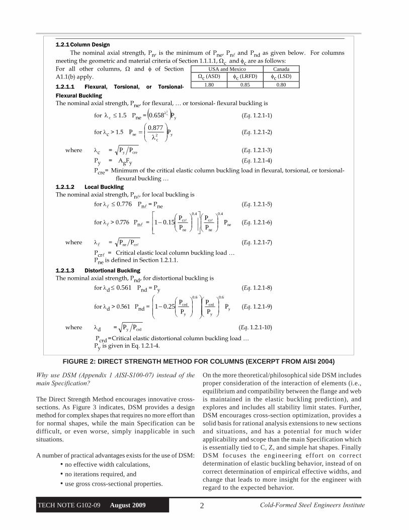
1.2.1 Column Design The nominal axial strength, Pn, is the minimum of Pne, Pnl and Pnd as given below. For columns
meeting the geometric and material criteria of Section 1.1.1.1, Ωc and φc are as follows: For all other columns, Ω and φ of Section A1.1(b) apply.
1.2.1.1 Flexural, Torsional, or Torsional-
Flexural Buckling The nominal axial strength, Pne, for flexural, … or torsional- flexural buckling is
for 5.1c ≤λ Pne = ( ) yP658.02cλ (Eq. 1.2.1-1)
for λc > 1.5 y2c
ne P877.0
P ⎟⎟⎠
⎞⎜⎜⎝
⎛
λ= (Eq. 1.2.1-2)
where λc = crey PP (Eq. 1.2.1-3)
Py = AgFy (Eq. 1.2.1-4)
Pcre= Minimum of the critical elastic column buckling load in flexural, torsional, or torsional-flexural buckling …
1.2.1.2 Local Buckling The nominal axial strength, Pnl, for local buckling is
for λl 776.0≤ Pnl = Pne (Eq. 1.2.1-5)
for λl > 0.776 Pnl = ne
4.0
ne
cr
4.0
ne
cr PP
P
P
P15.01 ⎟⎟
⎠
⎞⎜⎜⎝
⎛
⎥⎥⎦
⎤
⎢⎢⎣
⎡⎟⎟⎠
⎞⎜⎜⎝
⎛− ll (Eq. 1.2.1-6)
where λl = lcrne PP (Eq. 1.2.1-7)
Pcrl = Critical elastic local column buckling load … Pne is defined in Section 1.2.1.1.
1.2.1.3 Distortional Buckling The nominal axial strength, Pnd, for distortional buckling is
for λd 561.0≤ Pnd = Py (Eq. 1.2.1-8)
for λd > 0.561 Pnd = y
6.0
y
crd
6.0
y
crd PP
P
P
P25.01 ⎟
⎟⎠
⎞⎜⎜⎝
⎛
⎟⎟⎟
⎠
⎞
⎜⎜⎜
⎝
⎛
⎟⎟⎠
⎞⎜⎜⎝
⎛− (Eq. 1.2.1-9)
where λd = crdy PP (Eq. 1.2.1-10)
Pcrd = Critical elastic distortional column buckling load … Py is given in Eq. 1.2.1-4.
USA and Mexico Canada Ωc (ASD) φc (LRFD) φc (LSD)
1.80 0.85 0.80
FIGURE 2: DIRECT STRENGTH METHOD FOR COLUMNS (EXCERPT FROM AISI 2004)
Why use DSM (Appendix 1 AISI-S100-07) instead of themain Specification?
The Direct Strength Method encourages innovative cross-sections. As Figure 3 indicates, DSM provides a designmethod for complex shapes that requires no more effort thanfor normal shapes, while the main Specification can bedifficult, or even worse, simply inapplicable in suchsituations.
A number of practical advantages exists for the use of DSM:• no effective width calculations,
• no iterations required, and
• use gross cross-sectional properties.
Cold-Formed Steel Engineers Institute TECH NOTE G102-09 August 20093
(a) conventional shapes (b) optimized shapes
design effort main Specification medium DSM (Appendix 1) medium
design effort main Specification high or NA* DSM (Appendix 1) medium
*NA = not applicable or no design rules
FIGURE 3: DESIGN OF COLD-FORMED STEEL SHAPES MAIN SPECIFICATION AND DSM
DSM DESIGN GUIDE
In an effort to expand the use of the Direct StrengthMethod a Design Guide (AISI 2006) was recentlycompleted. The subsequent sections of this Note focuson this DSM Guide and provide the interested engineerwith further information on the application of DSM. TheGuide covers the following areas: elastic buckling,overcoming difficulties with elastic bucklingdetermination in the finite strip method, beam design,column design, beam-column design, productdevelopment and nearly 100 pages of design examples.
MEMBER ELASTIC BUCKLING
Solution MethodsTo use DSM the engineer needs to know the elastic bucklingloads or moment of the member. The Guide discusses andprovides references to a variety of solution methods for elasticbuckling of cold-formed steel members including the finiteelement method, the finite strip method, and closed-formhand solutions , but the focus is on the finite strip method.Typical results from a finite strip analysis are shown inFigure 5. From finite strip analyses local, distortional, andglobal buckling of a beam and/or column may be identified.
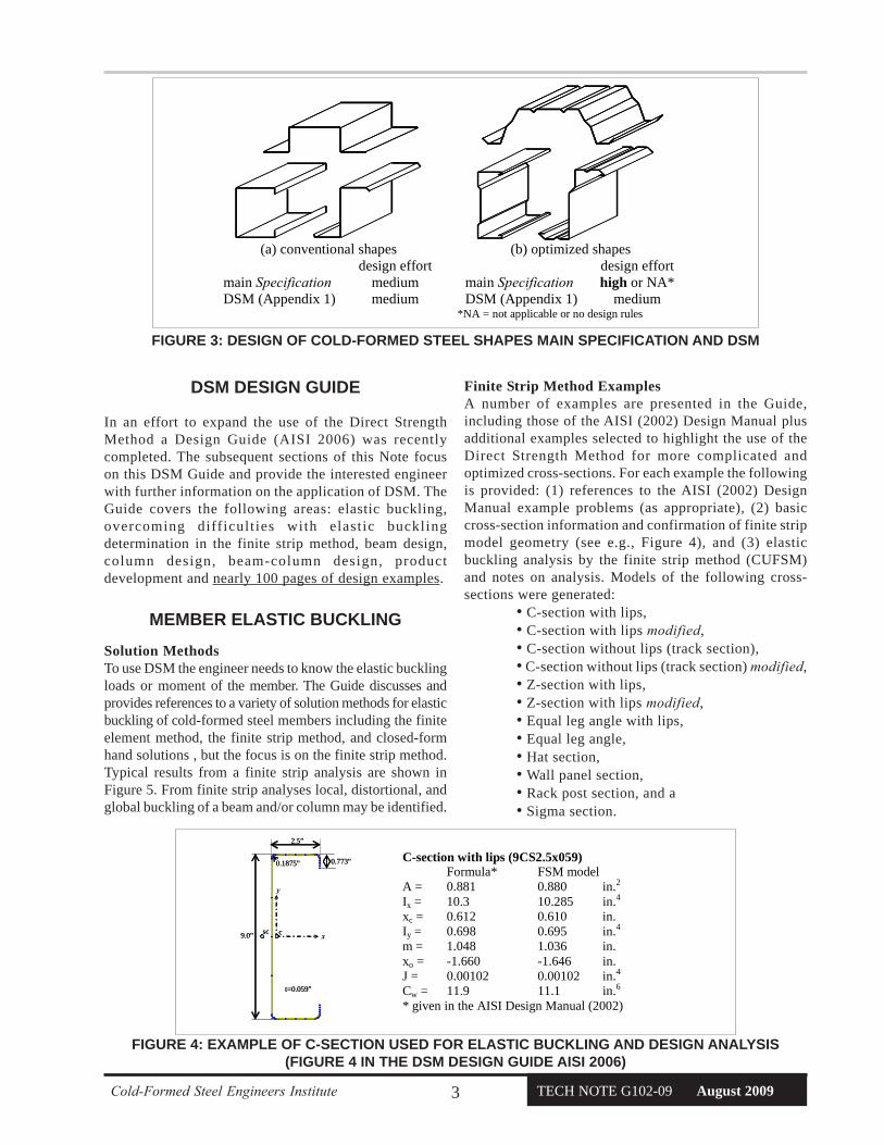
Finite Strip Method ExamplesA number of examples are presented in the Guide,including those of the AISI (2002) Design Manual plusadditional examples selected to highlight the use of theDirect Strength Method for more complicated andoptimized cross-sections. For each example the followingis provided: (1) references to the AISI (2002) DesignManual example problems (as appropriate), (2) basiccross-section information and confirmation of finite stripmodel geometry (see e.g., Figure 4), and (3) elasticbuckling analysis by the finite strip method (CUFSM)and notes on analysis. Models of the following cross-sections were generated:
• C-section with lips,• C-section with lips modified,• C-section without lips (track section),• C-section without lips (track section) modified,• Z-section with lips,• Z-section with lips modified,• Equal leg angle with lips,• Equal leg angle,• Hat section,• Wall panel section,• Rack post section, and a• Sigma section.
9.0”
2.5”
0.773”
t=0.059”
0.1875”
x
y
csc9.0”
2.5”
0.773”
t=0.059”
0.1875”
x
y
csc
C-section with lips (9CS2.5x059) Formula* FSM model A = 0.881 0.880 in.2 Ix = 10.3 10.285 in.4 xc = 0.612 0.610 in. Iy = 0.698 0.695 in.4 m = 1.048 1.036 in. xo = -1.660 -1.646 in. J = 0.00102 0.00102 in.4 Cw = 11.9 11.1 in.6 * given in the AISI Design Manual (2002)
FIGURE 4: EXAMPLE OF C-SECTION USED FOR ELASTIC BUCKLING AND DESIGN ANALYSIS
(FIGURE 4 IN THE DSM DESIGN GUIDE AISI 2006)
TECH NOTE G102-09 August 2009 Cold-Formed Steel Engineers Institute4
The heart of the DSM Design Guide is a series of exampleproblems. A typical page from the design examples isannotated, and provided in Figure 6. Each set of exampleproblems is focused on a particular cross-section. Forexample, for a C-section with lips (a stud section) thefollowing examples are provided:
C-section with lips-Flexural strength for a fully braced member (AISI 2002 Example I-8)-Flexural strength for L=56.2 in. (AISI 2002 Example II-1)-Effective moment of inertia (AISI 2002 Example I-8)-Compressive strength for a continuously braced column (AISI 2002, I-8)-Compressive strength at F
n=37.25 ksi (AISI 2002
Example III-1)-Beam-column design strength (AISI 2002 Example III-1)
The flexural strength for a fully braced member is similarin concept to determining the effective section for a memberat yield. The examples cover strength as well as serviceability
(deflection) determinations using the Direct Strength Method.Application of the Direct Strength Method to beam-columnsis also illustrated. In addition, reference is provided to the AISI(2002) Design Manual (noted in parentheses in the above list)where similar calculations are performed using the conventionaleffective width methods of the main Specification.
The design examples in the Guide span nearly 100 pages andcover a variety of cross-sections and situations, including:
•a C-section with web stiffeners added, includingstrong axis flexural strength and compressive strength withdifferent bracing conditions,
•a track section with flange stiffeners added,including flexural strength and compressive strength,
•a Z-section purlin, including flexural andcompressive strength for different bracing conditions,
•a Z-section purlin with stiffeners added and lip lengthmodified, including flexural and compressive strength,
•an equal leg angle with lips, including flexuralstrength, compressive strength, and compressive strengthexplicitly including eccentricity,
Cold-Formed Steel Engineers Institute TECH NOTE G102-09 August 20095
Mnl 94kip in⋅=
(Eq. 1.2.2-5)(Eq. 1.2.2-6)
Mnl Mne λl 0.776≤if
1 0.15Mcrl
Mne
⎛⎜⎝
⎞⎟⎠
0.4
⋅−⎡⎢⎢⎣
⎤⎥⎥⎦
Mcrl
Mne
⎛⎜⎝
⎞⎟⎠
0.4
Mne⋅⎡⎢⎢⎣
⎤⎥⎥⎦
λl 0.776>if
:=
(Eq. 1.2.2-7)(subscript "l" = "l")λl 1.22=λlMne
Mcrl:=
Local buckling check per DSM 1.2.2.2
(fully braced)Mne 127kip in⋅=Mne My:=
per DSM 1.2.2, Mn is the minimum of Mne, Mnl, Mnd. For a fully braced member lateral-torsional buckling will not occur and thus Mne = My, Mnl and Mnd must still be checked.
Mcrd 108kip in⋅=Mcrd 0.85 My⋅:=
Mcrl 85kip in⋅=Mcrl 0.67 My⋅:=
My 126.55 kip⋅ in⋅:=
Inputs from the finite strip analysis include:
Finite strip analysis of 9CS2.5x059 in pure bending as summarized in Example 3.2.1
Determination of the bending capacity for a fully braced member is equivalent to determining the effective section modulus at yield in the main Specification. see AISI (2002) example I-8.
8.1-1 Computation of bending capacity for a fully braced member (AISI 2002 Example I-8)
Given: a. Steel: Fy = 55 ksi
b. Section 9CS2.5x059 as shown to the rightc. Finite strip analysis results (Section 3.2.1)Required:1. Bending capacity for fully braced member2. Bending capacity at L=56.2 in. (AISI 2002 Example II-1)3. Effective moment of inertia4. Compression capacity for a fully braced member5. Compression capacity at a uniform compressive stress of 37.25 ksi (AISI 2002 Example III-1)6. Beam-column design (AISI 2002 Example III-1)
8.1 C-section with lips
Typical example from the DSM Design Guide
Mn
Ω b56kip in⋅=Ω b 1.67:=ASD:
φb Mn⋅ 84kip in⋅=φb 0.9:=LRFD:
The geometry of this section falls within the "pre-qualified" beams of DSM 1.1.1.2 and the higher φ and lower Ω of DSM Section 1.2.2 may therefore be used.
Mn 93kip in⋅=Mn min Mne Mnl Mnd( )( ):=
Predicted bending capacity per 1.3
Mnd 93kip in⋅=
(Eq. 1.2.2-8)(Eq. 1.2.2-9)
Mnd My λd 0.673≤if
1 0.22Mcrd
My
⎛⎜⎝
⎞⎟⎠
0.5
⋅−⎡⎢⎢⎣
⎤⎥⎥⎦
Mcrd
My
⎛⎜⎝
⎞⎟⎠
0.5
My⋅⎡⎢⎢⎣
⎤⎥⎥⎦
λd 0.673>if
:=
(Eq. 1.2.2-10)λd 1.08=λdMy
Mcrd:=
Distortional buckling check per DSM 1.2.2.3
Equation numbers refer to the relevant parts of DSM (Appendix 1 AISI 2004)
Problem Assumptions
Provided examplesFor each cross-section a number of different beam, column, and beam-column examples are provided.
Elastic BucklingElastic buckling results are the key to DSM. For this bending example, Mcrl and Mcrd are found from the finite strip analysis which is shown in thumbnail to the right, the same analysis is also fully examined in Chapter 3 of the Guide.
Global buckling checkThe beam is assumed to be fully laterally braced, thus the global buckling strength is simply the moment at first yield, My.
Local buckling checkThe Direct Strength expressions are used to provide the strength in local buckling (Mnl) including interaction with global buckling strength (Mne) as shown at right.
Distortional buckling checkThe Direct Strength expressions for distortional buckling are given to the right. Note that interaction with global buckling (Mne) is not included for distortional buckling.
Nominal strengthMn is the minimum of three individual strength checks. Conversion of nominal strength to allowable design strength (ASD) or design strength (LRFD) requires application of the appropriate safety and resistance factors which
are discussed in the examples.
•an equal leg angle, including flexural andcompressive strength,
•a hat section, including flexural strength,compressive strength for different bracing conditions, andbeam-column allowable strength,
•a wall panel section, including flexural strength for
intermediate and end panels with the top flange in compressionand flexural strength for bottom flange in compression,
•a rack post section, including flexural andcompressive strength, and
•a sigma section, including flexural andcompressive strength.
FIGURE 6: ANNOTATED EXAMPLE OF DSM DESIGN GUIDE EXAMPLE PROBLEMS
TECH NOTE G102-09 August 2009 Cold-Formed Steel Engineers Institute6
BEAM AND COLUMN CHARTS
The DSM Design Guide provides complete details fordevelopment of beam span tables or charts and columnheight tables or charts using the Direct Strength Method.An example beam chart is provided in Figure 7. In thisexample one can see how the local buckling strength, M
nl,
is a reduction below the global buckling strength, Mne
. Thepoint where M
nl and M
ne merge (approximately 9 ft) indicates
that local buckling no longer provides a reduction in thestrength of this beam - in the main Specification this occurswhen the stress used to determine the effective section (F
n)
is low enough that the section is fully effective at that stress.Further, the impact of distortional buckling on intermediatelength beams is clearly shown.
0 5 10 15 200
20
40
60
80
100
120
length (ft)
bend
ing
capa
city
(ki
p-in
.)
Mn L( )
Mne L( )
Mnl L( )
Mnd L( )
L
12
Mne
Mnl
Mnd
(c) Mn for Z-section with lips
FIGURE 7: EXAMPLE BEAM CHART FOR Z-SECTION(FIGURE 37(C) OF DSM DESIGN GUIDE AISI 2006)
BEAM-COLUMN DESIGN
Main Specification MethodologyAs described in the Guide conventional beam-column designfollows the basic methodology of the main Specification,and is a simple extension of the Direct Strength Method.The basic interaction equation, in ASD format, is as follows:
0.1≤Ω
+Ω
+Ω
yny
ymyb
xnx
xmxb
n
c
MMC
MMC
PP
ααwhere: P
n and M
n are determined from the Direct Strength
Method. The first-order required strengths (demands) are P,M
x and My, as determined from conventional linear elastic
analysis. Cm is the moment gradient factor, of which, the
method for determination is addressed in the mainSpecification and is unchanged. Finally, α , the momentamplification factor is 1- Ω
cP/P
E. P
E is the elastic buckling load
of the cross-section about the same axis as the primarybending moment, i.e., for strong axis moment M
x, global
buckling load PE is P
Ex. Global buckling loads may be
determined from main Specification equations or directlyfrom a finite strip analysis.
Future methods for beam-column designThe advantage of the Direct Strength Method is that thestability of the entire cross-section under a given axial load(P) or bending moment (M) is investigated. Local,distortional, and global buckling of the column or beam isexplored. It is natural to extend this idea to the stability ofthe cross-section under any given P and M combination.Where, now, the three buckling modes: local, distortional,and global buckling are explored under the actual P and Mcombination of interest, instead of separately for P andseparately for M. Such an analysis can lead to far differentbehavior than typically assumed in the interaction equationapproach used in the main Specification.
The fundamental difference between the interactionequations and a more thorough stability analysis can beunderstood by answering a simple question: for all cross-sections does the maximum axial capacity exist when theload is concentric? The interaction equation approach says,yes, any additional moment caused by a load away fromthe centroid will reduce the nominal strength of the cross-section. While a conservative answer, it is not alwayscorrect. If moving the axial load causes the relativecompressive demand on a weak part of the cross-section(say the lip) to be relieved the cross-section strength willbenefit from this. Interaction diagrams make some sensefor determining when a simple cross-section yields, butstability, this is another matter. A design example previewingthis new approach to beam-column design is provided inthe Guide.
PRODUCT DEVELOPMENT
Cold-formed steel is a versatile, easily formed material - itis one objective of DSM and the DSM Guide to helpmanufacturers take advantage of the potential in cold-formed steel for creating optimal cross-section shapes. Finaloptimization and bringing a product to market has as much,if not more, to do with manufacturing, constructability, andother practical matters as strength; however, DSM providesa way to quantitatively focus on the strength improvementsavailable to cold-formed steel designers/manufacturers.
One particularly important matter with regard to strengthis the application of resistance or safety factors for newlydeveloped members. For a newly developed cross-section,not covered by the main Specification provisions,
Cold-Formed Steel Engineers Institute TECH NOTE G102-09 August 20097
two basic avenues exist for strength prediction, as outlinedin the 2007 edition of the main Specification SectionA1.2(b): (a) determine the strength by testing and find φ viaChapter F of the Spec., or (b) determine the strength byrational analysis and use the blanket φ =0.80 (Ω=2.0)provided in A1.2(b). As Figure 8 shows although φ =0.8may be a rather low resistance factor it may take a large numberof tests (and relatively low scatter) to do better than this value.
5 10 15 20 25 300.7
0.75
0.8
0.85
0.9
φ
number of tests (n)
rational analysis φ value
VP=6.5% (minimum value)
VP=10% (low scatter)
VP=15% (typical scatter)
5 10 15 20 25 300.7
0.75
0.8
0.85
0.9
φ
number of tests (n)
rational analysis φ value
VP=6.5% (minimum value)
VP=10% (low scatter)
VP=15% (typical scatter)
FIGURE 8: COMPARISON OF RATIONAL ANALYSISWITH MAIN SPECIFICATION CHAPTER F METHOD-OLOGY (FIG. 40 IN DSM DESIGN GUIDE AISI 2006)
Beyond using the blanket rational analysis resistance orsafety factors, formal methods for pre-qualifying a newcross-section and using improved resistance factors havenot yet been formalized. However, the DSM Guideprovides specific guidance on how to take advantage ofthe testing that has already been performed in approxi-mating the reliability of a new product.
LIMITATIONS OF DSM: PRACTICAL ANDTHEORETICAL
Of course, limitations of DSM (as implemented in AISI-S100-07) exist as well, not the least of which is that themethod has only been formally developed for thedetermination of axial (P
n) and bending (M
n) strengths to
date. Existing main Specification provisions may be usedto supplement the strength prediction in other limit states(for example, shear or web crippling); otherwise, rationalanalysis or testing are a possible recourse. In addition DSMdoes not cover members with holes at this time; howeverAISI sponsored research is currently underway and newprovisions are under ballot at AISI in the Summer of 2009.
It is worth noting that DSM is overly conservative if veryslender elements are used. If a small portion of the cross-section (a very slender element) initiates buckling for thecross-section, DSM will predict a low strength for the entiremember. The effective width approach of the main
Specification will only predict low strength for the offendingelement, but allow the rest of the elements making up thecross-section to carry load (i.e., the main Specificationignores inter-element equilibrium and compatibility in thebuckling solution). The DSM approach can be overlyconservative in such cases; however, members with one veryslender element are inefficient and prone to serviceabilityproblems. The addition of folded longitudinal stiffeners inthe offending element will improve the strength, and theDSM strength prediction, significantly.
One additional difficulty that is discussed in the DSMDesign Guide is some of the complications that can arisein determining the elastic buckling load in global,distortional, and local buckling via the finite strip method.Topics covered in the Guide include the following:
• Indistinct local mode• Indistinct distortional mode• Multiple local or distortional modes (stiffeners)• Global modes at short unbraced lengths• Global modes with different bracing conditions• Influence of moment gradient• Partially restrained modes• Boundary conditions for repeated members• Members with holes• Boundary conditions at the supports not pinned• Built-up cross-sections
Each of the above listed topics is covered thoroughly withthe Guide and includes narrative, figures, and practicaladvice for engineers modeling cold-formed steel membersin a variety of design and development applications.
An example of interest is the change in the elasticbuckling behavior when external restraining elements areincluded in the model. For example, if rotational restraintis modeled as attached to the compression flange of a Z-section in bending the distortional buckling mode isretarded greatly, as shown in Figure 9. Given the recentlyadopted main Specification procedures for distortionalbuckling (see CFSEI TN G100-08) the ability to directlyadd restraint into a model is in some sense a complication,but in reality a definite advantage of the Direct StrengthMethod approach to strength. Even for those not using theDirect Strength Method, M
crd, is now required in the main
Specification and finite strip method solutions areallowed.
CONCLUSIONS
The Direct Strength Method (DSM) is a new method forthe design of cold-formed steel members. The methodprovides a rational analysis approach for designing a cold-formed member even with a highly unconventional crosssection. The approach employs member elastic bucklingsolutions to directly provide the member strength in global,
TECH NOTE G102-09 August 2009 Cold-Formed Steel Engineers Institute8
Primary Author of this Technical Note:Ben W. Schafer, Ph.D., P.E., Swirnow Family Faculty Scholar;Associate Professor and Chair, Department of Civil Engineering,Johns Hopkins University, Baltimore, MD
CFSEI Technical Review Committee: Rob Madsen, P.E., DevcoEngineering, Inc., chairman.
This “Technical Note on Cold-Formed Steel Construction” is published by the Cold-Formed Steel Engineers Institute (“CFSEI”). Theinformation provided in this publication shall not constitute any representation or warranty, express or implied, on the part of CFSEIor any individual that the information is suitable for any general or specific purpose, and should not be used without consulting with aqualified engineer, architect, or building designer. ANY INDIVIDUAL OR ENTITY MAKING USE OF THE INFORMATIONPROVIDED IN THIS PUBLICATION ASSUMES ALL RISKS AND LIABILITIES ARISING OR RESULTING FROM SUCHUSE. CFSEI believes that the information contained within this publication is in conformance with prevailing engineering standards ofpractice. However, none of the information provided in this publication is intended to represent any official position of the CFSEI orto exclude the use and implementation of any other design or construction technique.
References
1. North American Specification for the Design of Cold-Formed Steel Structural Members, American Iron and Steel Institute, Washington,DC, AISI/COS/NASPEC 2001.2. AISI Manual of Cold-Formed Steel Design, American Iron and Steel Institute, Washington, DC, 2002.3. Supplement 2004 to the North American Specification for the Design of Cold-Formed Steel Structural Members 2001 Edition: Appendix 1,Design of Cold-Formed Steel Structural Members Using Direct Strength Method, American Iron and Steel Institute, Washington, DC, 2004.4. Direct Strength Method (DSM) Design Guide, American Iron and Steel Institute, Washington, DC, 2006.5. North American Specification for the Design of Cold-Formed Steel Structural Members (AISI S100-07), American Iron and SteelInstitute, Washington, DC, 2007.6. Schafer, B.W., Ádány, S. (2006), “Buckling analysis of cold-formed steel members using CUFSM: conventional and constrained finitestrip methods.” Proceedings of the 18th International Specialty Conference on Cold-Formed Steel Structures, Department of CivilEngineering, University of Missouri-Rolla, Rolla, MO, 2006.
local (with global interaction), and distor-tional buckling. DSM does not employeffective width, and instead uses grossproperties, also DSM requires no iteration indetermination of the strength. The methodwas formally adopted for beams and columnsin 2004 as Appendix 1 of the North AmericanSpecification for the Design of Cold-FormedSteel Structural Members.
Recently a DSM Design Guide has beencompleted. The objective of the Guide is toaid engineers interested in applying DSM totheir own designs, or in developing newproducts that take advantage of the flexibilityof DSM. Key aspects of the new Guide arereviewed here, including: detailed explana-tion of member elastic buckling solutionsusing the finite strip method, a brief summaryof the topics covered in the design examples,a review of methods for developing beam andcolumn charts, as well as beam-columndesign, and how to use DSM in productdevelopment.
ACKNOWLEDGMENTS
The author gratefully acknowledges the American Ironand Steel Institute for their support in the development ofthe Direct Strength Method, and Direct Strength MethodDesign Guide.
Z-section (AISI 2002 Ex. I-10)
My=107.53kip-in.
Local Mcr
/My=0.85
Distortional Mcr
/My=0.77
Lateral-torsional
100
101
102
103
0
0.2
0.4
0.6
0.8
1
1.2
1.4
1.6
1.8
2
half-wavelength (in.)M
cr /
My
Z-section
My=107.53kip-in.
Local Mcr
/My=0.85 Distortional M
cr/M
y=1.30
due tok
φ
kφ
0.7 kip-in./rad/in.
FIGURE 9: EXAMPLE OF IMPACT OF ADDING ROTATIONALRESTRAINT TO THE FLANGE (FIGURE 33 OF THE DSM DESIGN