Cold Ironing Systemdue to environmental considerations, ships are being required to turn off their auxiliary generators and instead receive power from shore systems. this method of connect-ing ships to shore power-supply systems during berthing at the port is called cold ironing. (the term cold ironing origi-nates from when ships equipped with onboard steam genera-tors docked for repair. during repair, all of the pipes and boiler steel were cold, and thus the name cold ironing was used.) the true definition of cold ironing does not exactly apply to this process; however, connecting to shore power at a berth is becoming understood as cold ironing in the ship-ping industry. this method helps to minimize air pollution. the onboard crude oil generators are turned off while shore power is generated at a remote location, and a relatively less-polluting fuel is supplied to ships during cold ironing [1]–[4], [9]. shore power rated at 6.6 or 11 kV at 60-Hz frequency is supplied to ships by the use of multiple parallel feeder circuits to supply the required power to match the auxiliary generator load requirements of various ships. Unlike other industrial or commercial power systems, which, once energized, are tripped only in case of mainte-nance or under fault conditions, the cold ironing power sys-tem requires turning breakers on and off, posing a safety concern for operators. in addition, the electrical power sys-tem infrastructure of a major port needs to be supplemented to meet this need through the addition of several cold iron-ing substations and a local bulk-power substation (Bpss) with a high-voltage (HV) primary. the latter poses the addi-tional safety concern of dangerous touch potential. this arti-cle provides a cold ironing power system design using draft standard ieC/iso/ieee 80005-1 [5] criteria. the current status of this draft standard is also addressed.
Shore-to-Ship Power-Supply Systemshore-to-ship power-supply systems go by a variety of names: cold ironing, alternative maritime power (Amp), onshore power supply, shore-to-ship power supply, and shore-side electricity. the variations in name are strictly due to the usage adopted by the different organizations involved in this application and have no other signifi-cance. in this article, the authors recommend the adop-tion of the name shore-to-ship power supply, which is descriptive of the application implemented.
during berthing, vessels will require different power, depending upon the type and size of the vessel. the power requirements of various vessel types and sizes presented in table 1 are taken from current draft standard ieC/iso/ieee 80005-1 [5].
to connect a berthing ship to shore power for cold iron-ing operation, a dedicated substation transformer of ade-quate rating with secondary voltage of either 6.6 or 11.0 kV is required. the term dedicated substation transformer means only one ship connection to one transformer to satisfy the galvanic isolation requirements of the current draft stan-dard [5]. such a design will protect the ship power system from abnormalities in the shore power system, especially if the shore power system is used for power distribution to other facilities within the port area. many power system grounding problems and stray currents associated with other port facilities can affect the ship power-supply ground
fault protection, unless the shore power system has its own grounding zone provided by a dedicated transformer with a neutral grounding resistor (ngr), as shown Figure 1, for connection to the ship, as shown in Figure 2.
most of the ships under construction today are designed for 60-HZ operation a standard order. At an added cost, 50-HZ ships are considered a special order and require an additional footprint for the 60–50-Hz frequency converters (FCs) on the ship for connection to 60-Hz shore power. therefore, it is expected that the majority of ships will require a 60- and not 50-Hz power supply. where the utility power supply is 50 Hz, FCs will be required on shore before the shore power substation transformer [7]. the design of a cold ironing project requiring FCs is the subject of another article and thus will not be addressed here. A major port with several cold ironing projects may require a Bpss with the HV primary close to the port facilities. (see Figure 3.) A dangerous touch potential can be caused by high line–ground fault on HV side of such a Bpss without appropriate design considerations. this article provides a design method for mitigating such dangerous touch potential.
Unique Featuresthe shore power transformer is kept energized even when a ship is not connected to draw shore power, and thus a trans-former with low no-load losses is desirable. each cold ironing operation requires the power circuit breakers of both the shore and ship power systems to close and then open, posing unusual strain on the breakers. operators perform connec-tions of shore power to ships by using cable management systems (Cmss), a combination of flexible cables and power plugs/receptacle assemblies. the power plugs are very heavy and require cranes to maneuver them before being plugged into the receptacles. Applications such as cruise ships require continuity check wiring monitoring of emergency trip cir-cuits and separate plug and receptacle assemblies. each cold ironing operation requires two synchronizing operations, one for transferring the ship’s auxiliary generator load to shore power and the second for transferring the ship’s load back to the ship’s auxiliary generator. physically, the substation switchgear alternative maritime power (Amp)-A and the load interrupter switchgear emergency shutdown (es) and Amp boxes shown in Figure 1 may all be physically far apart from each other. these unique features of the power system design and operation pose many safety concerns. the design approach presented here considers and mitigates these safety concerns. if the movement of the ship causes the flexi-ble cable to pull the continuity circuit pin that breaks the
TabLE 1. THE POWER REQUIREMENTS aT bERTH.Ship Type Voltage (kV) Power (MVA)
Cruise ships 6.6 or 11 16–20Container ships 6.6 7.5Liquefied natural gas carriers
6.6 or 11 10.7
Ro-Ro ships 11 6.5 Tankers 6.6 7.2
IEEE
In
du
str
y A
pp
lIc
AtI
on
s M
Ag
AzI
nE
• M
Ay
|ju
nE
2014
• w
ww
.IEE
E.o
rg
/IA
s
26
continuity of the circuit, then the circuit breakers would open auto-matically on both the shore and the ship systems. emergency trip push buttons are also installed on the shore and the ship at specific loca-tions to manually trip the circuit breakers in case of emergency.
Unique Power System Componentswhat follows is a list of the unique components of cold iron-ing power systems.
▪ A three-pole grounding switch is used to discharge medium-voltage (mV) cables [16].
▪ A three-pole main disconnect switch (ds) is used for the isolation of Amp boxes.
▪ the standard ratings of the female power receptacle are 350 or 500 A at both 6.6 and 11.0 kV. they consist of six pins: three power, one ground, and two pilots. the ground and pilot pins make the last and first break for safety. pilot pins are used for the continuity check circuit and the emer-gency trip circuits [5].
▪ matching male power plugs assembled at the end of flexi-ble power cables are designed to make safe connections. the power plug standard rat-ings are also 350 or 500 A at both voltage ratings 6.6 and 11.0 kV [5].
▪ A Cms is used for reeling and unreeling the flexible power cable. Figure 2 shows the Cms located on ship, but it can be on shore on a mov-able trolley. safety limit switches are built into the cable reel system to avoid pulling tension on the cable system and the plug/recepta-cle assembly [5].
▪ separate receptacle and matching plug assemblies are implemented for the commu-nication and emergency trip circuits.
▪ mechanically keyed interlocks between the power receptacle cover, grounding switch, and main ds are implemented to ensure that the power system is de-energized and the cable
Two Sets of 3–1/C #2/0 AWG (8 kV) and 1–2/0 GND, 300’ (TYP.)
1,200 A15 kV 1,200 A
15 kV
Load InterrupterSWGR ES
3
SA
600/5
600/5
SAD1 D1 D1
A1 B1
50/525 A
CONT.6.6 kV–120 V
3
86
SAR1
R1 R2 R2
34.5 kV, 600 A
Two Sets ofU/G Cable3 #4/0 (35 kV)
2 Sets of3 #500MCM (8 kV),1–#3/0 GND500’
51G
86
The cold ironing power system—one-line diagram. 1
27
IEEE Ind
ustr
y A
pp
lIcA
tIon
s MA
gA
zInE •
MA
y|
jun
E 2014 • w
ww
.IEEE.or
g/IA
s
system is discharged by grounding switches [16] when shore-to-ship connections are performed.
▪ A high-resistance grounded (Hrg) power system with an ngr and associated ground fault protection relay is used [13]. the ngr is monitored continu-ously for open- or short-circuit conditions, and breakers open automatically on both sides if any of these abnormalities are detected.
▪ multifunction individual protection relays on each feeder to the power receptacle include a minimum device 50/51, 50/51n as well as a live line showing lights for the protection of the equipment and safety of the operators.
▪ the transformer primary protec-tion includes multifunction relays with minimum devices 50/51, 50/51n, 59, and 27.
▪ the transformer secondary power system protection includes multi-function relays with minimum devices of 50/51, 50/51n, 32, 59, 27, 47, 46, 81o, 81U, and 25.
▪ the power transformer protection devices include 49w for a dry-type cast-coil transformer and devices 49w, 71Q, 26Q, 63sr, and 63pr for the oil-filled trans-former. All of the devices listed here for the oil-filled transformer are not in the current draft stan-dard [5]. Considering the applica-tion of the upcoming FCs where the utility power frequency is 50 Hz will require additional power transformers on the line side of the FC, whereas the dedicated shore power transformers will still be required for the cold ironing power-supply system. these addi-tional transformers may require all of the protection devices asso-ciated with the oil-filled trans-former, depending upon the configuration and design of the FC package at a particular port.
Substation Transformer Ratingto accommodate the varying load requirements of the ships shown in table 1, the overload capability of the transformer should be considered. Both the liquid-immersed and the dry-type transformer overload guides are con-tained in American national standards institute/ieee C57.91 and C57.96 [7]. Forced-air (FA) cooling is a common method that can increase the loading of both types of transformers. For a liq-uid-immersed transformer, FA options can offer 12% overload at .2 5# mVA and 25% for anything larger. For a dry-
type transformer, FA options can offer 33-1/3% overload at .3 75# mVA and 25% for anything larger.
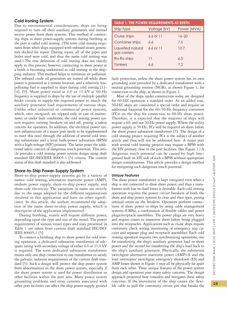
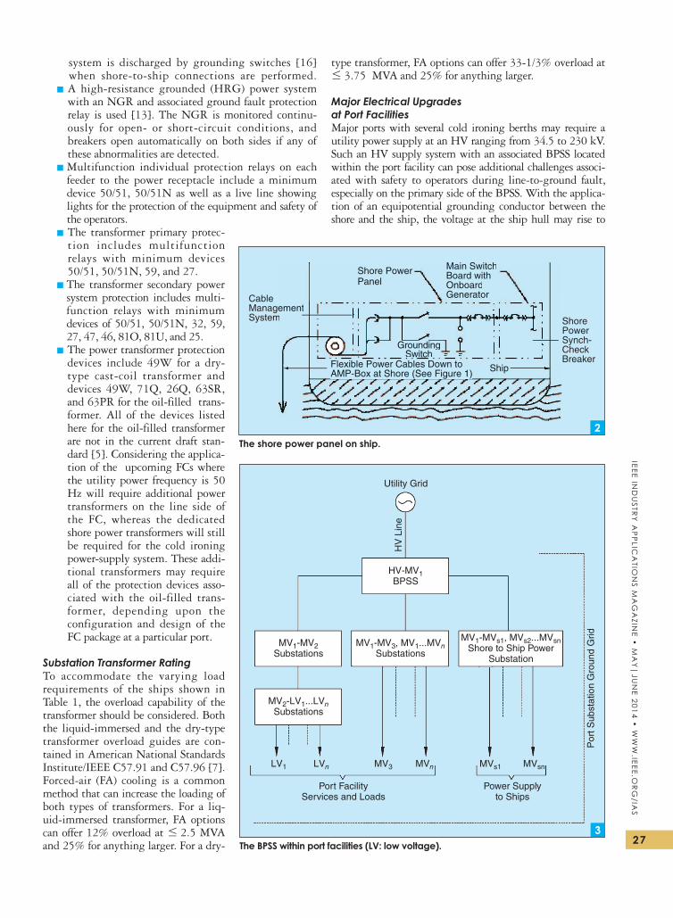
Major Electrical Upgrades at Port Facilitiesmajor ports with several cold ironing berths may require a utility power supply at an HV ranging from 34.5 to 230 kV. such an HV supply system with an associated Bpss located within the port facility can pose additional challenges associ-ated with safety to operators during line-to-ground fault, especially on the primary side of the Bpss. with the applica-tion of an equipotential grounding conductor between the shore and the ship, the voltage at the ship hull may rise to
Shore PowerPanel
Main SwitchBoard withOnboardGenerator
ShorePowerSynch-CheckBreaker
Ship
CableManagementSystem
Flexible Power Cables Down toAMP-Box at Shore (See Figure 1)
GroundingSwitch
Shore PowerPanel
Main SwitchBoard withOnboardGenerator
Ship
ementm
Flexible Power Cables Down toAMP-Box at Shore (See Figure 1)
GroundingSwitch
The shore power panel on ship.2
Utility Grid
HV-MV1BPSS
MV1-MV3, MV1...MVnSubstations
MV1-MVs1, MVs2...MVsnShore to Ship Power
Substation
Power Supplyto Ships
Port FacilityServices and Loads
MV1-MV2Substations
MV2-LV1...LVnSubstations
HV
Lin
e
Por
t Sub
stat
ion
Gro
und
Grid
MVs1 MVsnMV3 MVnLV1 LVn
The bPSS within port facilities (LV: low voltage). 3
IEEE
In
du
str
y A
pp
lIc
AtI
on
s M
Ag
AzI
nE
• M
Ay
|ju
nE
2014
• w
ww
.IEE
E.o
rg
/IA
s
28
dangerous touch voltage during a line-to-ground fault on the primary HV side of the Bpss.
Grounding and Touch Potentialto make an Hrg power system, ship generators are either grounded by individual neutral resistors or kept ungrounded to use one common homopolar grounding scheme [2]. the connection of a dedicated ship to a dedi-cated shore power substation has led the design of the shore power system to be an Hrg with a ground fault sensor relay at the ngr to minimize equipment damage during line–ground faults [5], [10], [13].
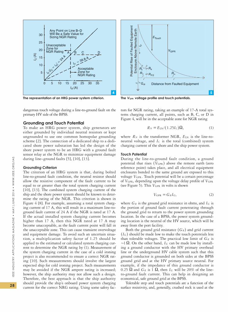
Grounding Criterionthe criterion of an Hrg system is that, during bolted line-to-ground fault condition, the neutral resistor should allow the resistive component of the fault current to be equal to or greater than the total system charging current [10], [13]. the combined system charging current of the ship and the shore power system should be known to deter-mine the rating of the ngr. this criterion is shown in Figure 4 [8]. For example, assuming a total system charg-ing current of 17 A, this will result in a maximum line-to-ground fault current of 24 A if the ngr is rated at 17 A. if the actual installed system charging current becomes higher than 17 A, then this ngr rated at 17 A may become unacceptable, as the fault current point will fall in the unacceptable zone. this can cause transient overvoltage and equipment damage. to avoid such an uncertain situa-tion, a multiplication safety factor of 1.25 should be applied to the estimated or calculated system charging cur-rent to determine the ngr rating by (1). measurement of the system charging current in the case of a cold ironing project is also recommended to ensure a correct ngr rat-ing [10]. such measurements should involve the largest expected ship for cold ironing project. such measurements may be avoided if the ngr ampere rating is increased; however, the ship authority may not allow such a design. therefore, the best approach is that the ship authority should provide the ship’s onboard power system charging current for the correct nrg rating. Using some safety fac-
tors for ngr rating, taking an example of 17-A total sys-tems charging current, all points, such as B, C, or d in Figure 4, will be in the acceptable zone for ngr rating
/ . ,R E I1 25LNN C X= ^ h (1)
where RN is the transformer ngr, ELN is the line-to-neutral voltage, and IC is the total (combined) system charging current of the shore and the ship power system.
Touch Potentialduring the line-to-ground fault condition, a ground potential that rises VGPR^ h above the remote earth (zero reference point) takes place, and all electrical equipment enclosures bonded to the same ground are exposed to this voltage .VGPR touch potential will be a certain percentage of ,VGPR depending upon the voltage delay profile of VGPR (see Figure 5). this VGPR in volts is shown
,V G IGPR R G= (2)
where GR is the ground grid resistance in ohms, and IG is the portion of ground fault current penetrating through the ground grid to return to the power system grounding location. in the case of a Bpss, the power system ground-ing location is the neutral of the HV source, which will be away from the port facility.
Both the ground grid resistance GR^ h and grid current IG^ h should be made low to make the touch potentials less
than tolerable voltages. the practical low limit of GR is .1+ X on the other hand, IG can be made low by install-
ing a ground conductor with the HV primary overhead line or the underground HV cable system such that this ground conductor is grounded on both sides at the Bpss ground grid and at the HV primary source neutral. For example, if the impedance of this ground conductor is 0.25 X and GR is 1 X, then IG will be 20% of the line-to-ground fault current. this can help in designing an economical, safe ground grid at the Bpss.
tolerable step and touch potentials are a function of the surface resistivity, and, generally, crushed rock is used at the
Any Point on Line B–DWill Be a Safe Value forSizing NGR Rating
UnacceptableZone forNGR Rating
I C (A
)
5
0 5 10 15 20IR (A)
I F (I C = I R
) = 2
4 A
IF = 39.8 A
25 30 35
10
15
20
25
30
AcceptableZone forNGR Rating
A B C D
Any Point on Line B–DWill Be a Safe Value forSizing NGR Rating
UnacceptableZone forNGR Rating
I F (I C = I R
) = 2
4 A
IF = 39.8 A
AcceptableZone forNGR Rating
A B C D
The representation of an HRG power system criterion.4
ETouch
VGPR
Rt
R1 RoRF/2
Rk
GR
I F
Distance from Faulted Equipment
Pot
entia
l Ris
e of
Fau
lted
Equ
ipm
ent
Enc
losu
re A
bove
Rem
ote
Ear
th
ETouchEE
VGPRVV
Rt
R1 RoRF/2FF
Rk
GR
I F
Distance from Faulted Equipment
Enc
losu
re A
bove
Rem
ote
Ear
th
The VGPR voltage profile and touch potentials.5
29
IEEE Ind
ustr
y A
pp
lIcA
tIon
s MA
gA
zInE •
MA
y|
jun
E 2014 • w
ww
.IEEE.or
g/IA
s
HV substation ground grid design due to its higher resistivity [11]. ieee stan-dard 80 is used by the industry to pro-vide a safe substation ground grid design based upon the tolerable touch and step potentials versus calculated touch and step potentials during a line-to-ground fault within the substation. to be consid-ered safe without the electric shock haz-ard, this safety analysis is related to how much current from hands to feet (touch potential) or foot to foot (step potential) flows through the human body and for how long. the maximum line-to-ground fault current, clearing time of the fault by the ground fault protection device, and resistivity of the earth surface in the substation and around the energized electrical equipment are needed for safety analysis. ieee standard 80 establishes the safe limits of potential differences (tolerable voltages) between points that can be contacted by the human body. the tolerable voltage equations provided in ieee standard 80 are derived from the research work of dalziel. the stan-dard provides simplified formulas for cal-culating 50- and 60-Hz ac voltages that can be tolerated by 99.5% of the popula-tion. step voltages are generally three times higher than the touch voltage for similar conditions. A simplified formula for tolerable touch voltage is
. ,E I R p1 5T ucho B B= +^ h (3)
where RB is the human body resistance generally assumed as 1,000 X (equivalent resistance of the human body), p is the electrical resistivity in ohm-meters for the material on which the person is standing (assumed here to be homogeneous material), and IB is the tolerable body current in amperes for a person weighing 110 lb (equal to 0.116/√t), where t is the tripping time of the circuit breaker in seconds or the duration of the touch voltage.
Using (3), tables 2 and 3 provide the tolerable ac touch voltages in volts (rms), where a line-to-ground fault current is such that current flow through the grounding grid IG is 6.78 kA (+1/3 of 20-kA ground fault current). this is based upon the assumption that, due to the split factor of ground fault return current, 2/3 of the ground fault current returns to the power source via the ground-ing conductor installed with the supply conductors.
suppose the substation ground grid resistance is 1 X and the ground grid current is 7 kA, then the VGPR will be 7 kV, which may result in not exceeding the tolerable touch voltage, as the touch voltage is a fraction of ,VGPR as shown in Figure 5. the voltage decay profile VGPR is related to the characteristics of soil under the ground grid and the surrounding area.
For the Bpss, it can be assumed that the HV line can have a ground fault close to the Bpss and that it will be
the utility upstream breaker’s protection device that will clear this fault. For a short period until the fault is cleared, it can raise the Bpss to a dangerous ,VGPR and touch potential at the ship hull may also be high due to the equipotential grounding conductor. to minimize such a problem of dangerous touch potential, if there is a ground conductor with the HV feeders, then VGPR may be only 20% (as explained earlier in the example using ground grid resistance of 1 X and ground conductor resistance of 0.25 X), which is 1.4 kV (0.2 # 7 kV) less than the tolera-ble touch potential.
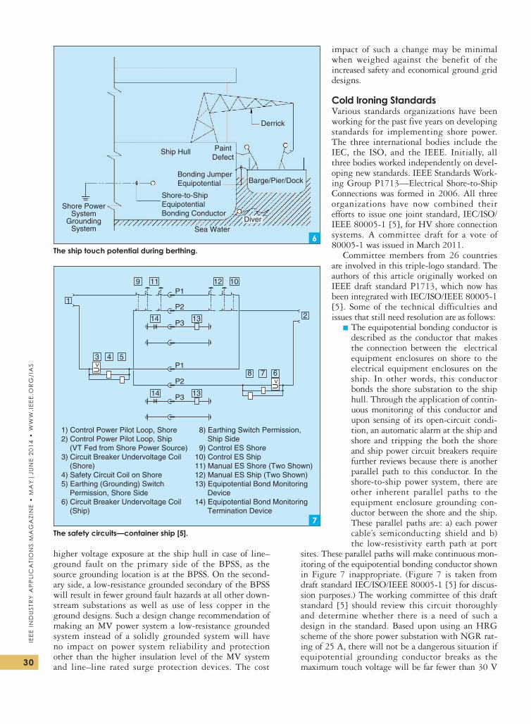
in the case of a ship hull bonded to the shore by equi-potential bonding, the conductor voltage on the ship can be 1.4 kV—in the absence of an insulating surface around swimmers. the barge operators may be exposed to dan-gerous touch potential due to the potential difference between the ship hull and the barge, as shown in Fig-ure 6. to solve such a problem, the application of safety bonding conductors between the ship hull and the barge is recommended. swimmers should use gloves and swim suits made of nonconducting material, or warning signs should be posted to direct swimmers away from the busy port facility. the fault current at shore power facilities, especially the Bpss, should use a ground conductor installed with HV feeders where it is an overhead line or the underground HV feeder cables.
in a certain port area where it is not possible to use crushed rock for the Bpss, another option is to work with the utility company that provides power to the port to perhaps change the Bpss delta-wye transformer secondary windings grounding configuration to a low-resistance grounding instead, solidly grounding. this will limit
TabLE 2. THE TOLERabLE aC TOUCH VOLTaGES.
Time (s)
wet concrete Low Range p = 21 X m
wet concrete Low Range p = 100 X m
Dry Soil p = 1,000 X m Remarks
0.03 691 770 1,674 Note 1 0.03 691 770 1,674 Note 1 0.05 535 597 1,297 Note 1 Note 1: This table conservatively assumes that the hand and foot contact resistances are equal to zero and that glove and shore resistances are also equal to zero.
TabLE 3. THE TOLERabLE aC TOUCH VOLTaGES.
Time (s)
wet concrete Low Range p = 21 X m
wet concrete Low Range p = 100 X m
Dry Soil p = 1,000 X m Remarks
0.03 2,700 2,779 3,684 Note 2 0.05 2,092 2,153 2,853 Note 2 0.10 1,479 1,522 2,018 Note 2Note 2: This table was developed assuming that the person in the substation has proper gloves and shoes with an assumed resistance of 3,000 X. This will change the value of human body resistance in (3) to 4,000 X.
IEEE
In
du
str
y A
pp
lIc
AtI
on
s M
Ag
AzI
nE
• M
Ay
|ju
nE
2014
• w
ww
.IEE
E.o
rg
/IA
s
30
higher voltage exposure at the ship hull in case of line–ground fault on the primary side of the Bpss, as the source grounding location is at the Bpss. on the second-ary side, a low-resistance grounded secondary of the Bpss will result in fewer ground fault hazards at all other down-stream substations as well as use of less copper in the ground designs. such a design change recommendation of making an mV power system a low-resistance grounded system instead of a solidly grounded system will have no impact on power system reliability and protection other than the higher insulation level of the mV system and line–line rated surge protection devices. the cost
impact of such a change may be minimal when weighed against the benefit of the increased safety and economical ground grid designs.
Cold Ironing StandardsVarious standards organizations have been working for the past five years on developing standards for implementing shore power. the three international bodies include the ieC, the iso, and the ieee. initially, all three bodies worked independently on devel-oping new standards. ieee standards work-ing group p1713—electrical shore-to-ship Connections was formed in 2006. All three organizations have now combined their efforts to issue one joint standard, ieC/iso/ieee 80005-1 [5], for HV shore connection systems. A committee draft for a vote of 80005-1 was issued in march 2011.
Committee members from 26 countries are involved in this triple-logo standard. the authors of this article originally worked on ieee draft standard p1713, which now has been integrated with ieC/iso/ieee 80005-1 [5]. some of the technical difficulties and issues that still need resolution are as follows:
▪ the equipotential bonding conductor is described as the conductor that makes the connection between the electrical equipment enclosures on shore to the electrical equipment enclosures on the ship. in other words, this conductor bonds the shore substation to the ship hull. through the application of contin-uous monitoring of this conductor and upon sensing of its open-circuit condi-tion, an automatic alarm at the ship and shore and tripping the both the shore and ship power circuit breakers require further reviews because there is another parallel path to this conductor. in the shore-to-ship power system, there are other inherent parallel paths to the equipment enclosure grounding con-ductor between the shore and the ship. these parallel paths are: a) each power cable’s semiconducting shield and b) the low-resistivity earth path at port
sites. these parallel paths will make continuous mon-itoring of the equipotential bonding conductor shown in Figure 7 inappropriate. (Figure 7 is taken from draft standard ieC/iso/ieee 80005-1 [5] for discus-sion purposes.) the working committee of this draft standard [5] should review this circuit thoroughly and determine whether there is a need of such a design in the standard. Based upon using an Hrg scheme of the shore power substation with ngr rat-ing of 25 A, there will not be a dangerous situation if equipotential grounding conductor breaks as the maximum touch voltage will be far fewer than 30 V
The ship touch potential during berthing.
Shore PowerSystem
GroundingSystem Sea Water
PaintDefect
Derrick
Ship Hull
Bonding JumperEquipotential
Shore-to-ShipEquipotentialBonding Conductor
Barge/Pier/Dock
Diver
6
The safety circuits—container ship [5].
1) Control Power Pilot Loop, Shore2) Control Power Pilot Loop, Ship (VT Fed from Shore Power Source) 3) Circuit Breaker Undervoltage Coil (Shore)4) Safety Circuit Coil on Shore5) Earthing (Grounding) Switch Permission, Shore Side6) Circuit Breaker Undervoltage Coil (Ship)
8) Earthing Switch Permission, Ship Side 9) Control ES Shore10) Control ES Ship11) Manual ES Shore (Two Shown)12) Manual ES Ship (Two Shown)13) Equipotential Bond Monitoring Device14) Equipotential Bond Monitoring Termination Device
P3
P2
P1
P3
P2
P19 11
14 13
12 10
1
3 4 5
U<
14 13
6
2
78
U<
7
31
IEEE Ind
ustr
y A
pp
lIcA
tIon
s MA
gA
zInE •
MA
y|
jun
E 2014 • w
ww
.IEEE.or
g/IA
s
in a line-to-ground fault anywhere on shore-to-ship power system. the ground fault relay at the ngr will still operate properly as the current will return via cable shield and earth if the equipotential ground-ing conductor is lost.
▪ For a cruise ship, an application of an ngr ds to ground the ngr at the ship’s hull during the cold ironing period and then to ground the ngr on shore during noncold ironing periods has no technical explana-tion in the current draft standard [5]. see Fig-ure 8 for such a ds at the ngr. A separate plug and receptacle assembly is needed for the imple-mentation of such a ds, which can pose an addi-tional task for the opera-tors and safety concerns and should be evaluated by the committee to see whether there is a need for such a ds. in the draft standard [5], for a container ship and other ships, there are no such requirements for an ngr ds.
▪ For a cruise ship, an ngr rating of 540 X as shown in the draft stan-dard [5] will allow a maximum of 7-A system charging current at 6.6 kV and 11.8 A at 11.0 kV. this rating may prove to be inadequate if the combined total system charging current of the shore and the ship power system exceeds the 7- or 11.8-A ratings for the 6.6- or the 11.0-kV power-supply system, respectively. the previously discussed grounding criteria section should be stated in the standard, and the current ratings should be made close to 20–25 A, which will make the ngr ohm rating much lower than the 540 X recommended in the standard [5]. in examining the discussion on equipment damage at the fault location during a line-to-ground fault on an Hrg power system where impedance is at the fault location, we may conclude that a 25-A ngr is better than an ngr rated at 540 X [10]. see Figure 9 for the shore power transformer grounding configuration with ngr.
▪ not all applicable ieee standards appear to be listed in the draft ieC/iso/ieee 80005-1 standard. this
may cause project installation approval delays in the United states, where the interpretation of all ieC-listed standards in the draft standard [5] may not apply. A review of normative ieC references listed under section 2 of the draft standard [5] should be con-ducted by working members to add applicable ieee standards to correct this situation.
▪ the authors do not believe that the ip-based communi-cations system of the draft standard 80005-2 [6] is nec-essary, especially for container ships in the United states where FCs are not required. it is not clear what is perceived as so critical about the shore power trans-former and other associated power system switching equipment where all protection devices are properly sized and set to protect the equipment during fault conditions. this assumes that the equipment is ade-quately sized and then trained operators are on duty both on the port and at the ship during cold ironing
9The container ship grounding without an NGR disc switch.
IEEE
In
du
str
y A
pp
lIc
AtI
on
s M
Ag
AzI
nE
• M
Ay
|ju
nE
2014
• w
ww
.IEE
E.o
rg
/IA
s
32
period. Control monitoring and communication system between shore and the ship should be kept simple and practical to facilitate cargo loading and unloading oper-ations without an unnecessary burden to the business.
▪ the ip-based communication system currently described in ies/iso/ieee 80005-2 [6] features a secure ip address for each ship and the alarm signal uses a user datagram protocol. this approach will require it professionals to develop a system that will be compatible with open protocols for interface devices on the ship and the shore to avoid being limited to proprietary equipment from one manufacturer. this current draft communication system standard between ship and shore perhaps should consider some changes to the wording prior to its enforcement to various cate-gories of ship’s cold ironing projects. such a change of wording may simply be “if any cold ironing project needs to implement such a requirement, they should do so outside of this standard.”
basic Safety Trainingports that have installed cold ironing projects have real-ized the need for special training for the shore and ship operators involved in the cold ironing operations. this section provides the basic training needed for the opera-tors to enhance safety.
▪ All persons must go through the arc-flash hazard training.
▪ All installed equipment must meet ieee standard 1584 [14] and national Fire protection Association standard 70e [15] and have proper energy labels and danger signs.
▪ All operators must go though the training for basic technical knowledge and understanding of cold iron-ing power systems.
▪ training on the sequence of operation and steps needed for cold ironing operation must be required for all operators.
▪ the person in charge (piC) on the shore and the piC on the ship must make all communications during cold ironing operation.
▪ preassigned contact lists for electrical emergencies on shore or the ship must be clearly defined to avoid delays in case of emergency.
Conclusion and Recommendations ▪ the unique features and components of the cold ironing power system that have a direct impact on the safety have been discussed. to enhance safety through the design of the power system requires the use of ground-discharging dss, mechanically keyed interlocks, component safety devices to automatically trip the power system under abnormal operating condition, emergency trip stations, and an Hrg sys-tem and appropriate power system protection.
▪ mitigating the dangerous touch potential caused by a line-to-ground fault on the HV side of the local Bpss can be achieved by installing a grounding conductor between the Bpss and the utility supply substations. the port authority needs to coordinate and work with the local utility to see if a grounding conductor with
an HV incoming line can be implemented. it also appears that there are benefits in requesting the utility company to allow the use of a Bpss transformer with the primary winging solidly grounded, delta winding in the middle, and the secondary winding with resis-tance grounded configuration.
▪ operator training for the operation of the cold iron-ing power system and a need for a piC on both the shore and ship is highly recommended. port and ship authorities are working on standardizing such procedures.
▪ this article also provides the current status of both ieC/iso/ieee draft standards 80005-1 [5] and 80005-2 [6].
References[1] d. paul and V. Haddadian, “Cold ironing power system grounding and
safety analysis,” in Proc. IEEE/IAS Conf., Hong Kong, oct. 2005, pp. 1503–1511.
[2] d. paul and B. Chavdarian, “Closer look at the grounding of shore to ship power supply system,” in Proc. IEEE Industrial Commercial Technical Conf., Calgary, AB, Canada, may 2009, pp. 1–7.
[3] K. l. peterson, B. Chavdarian, m. islam, and C. Cayannan, “tackling ship pollution from the shore,” IEEE Ind. Applicat. Mag., vol. 15, no. 1, pp. 56–60, Jan./Feb. 2009.
[4] d. paul and V. Haddadian, “transient overvoltage protection of shore-to-ship power supply system,” IEEE Trans. Ind. Applicat., vol. 47, no. 3, pp. 1193–1200, may/June 2011.
[5] Cold Ironing—Part 1: High Voltage Shore Connection (HVSC) Systems—Gen-eral requirements, ieC/iso/ieee standard 80005-1.
[6] Cold Ironing—Part 2: High Voltage Shore Connection (HVSC) Systems—Com-munications Interface Description, ieC/iso/ieee standard 80005-2.
[7] X. yang, g. Bai, and r. schmidhalter, “shore to ship converter system for energy savings and emission reduction,” in Proc. 8th Int. Conf. Power Electronics–ECCE Asia, shilla Jeju, Korea, may 30–June 3, 2011, pp. 2081–2086.
[8] d. paul and V. Haddadian, “shore to ship power supply system for a cruise ship,” in Proc. IEEE Industry Applications Society Annu. Conf., Houston, tX, 2009, pp. 1–7.
[9] dr. y. Khersonsky, d. paul, and K. peterson, “Cold ironing—Connecting marine and navy ships,” in Proc. World Maritime Technology Conf., london, mar. 6–16, 2006.
[10] d. paul, p. sutherland, and s. panetta, “A novel method of measuring inherent power system charging current,” IEEE Trans. Ind. Applicat., vol. 47, no. 6, pp. 2330–2342, nov./dec. 2011.
[11] Guide for safety in AC Substation Grounding, ieee standard 80.[12] Recommended Practice for Electric Power Distribution for Industrial Plants,
ieee standard 141. [13] Recommended Practice for Grounding of Industrial and Commercial Power
Systems, ieee standard 142. [14] IEEE Guide for Performing Arc Flash Hazard Calculations, ieee stan-
dard 1584-2004a, 2004.[15] Standard for Electrical Safety in the Workplace, nFpA standard 70e, 2004.[16] d. paul, p. B. Chavdarian, and V. Haddadian, “Cable-capacitance
discharge time with and without the application of grounding device,” IEEE Trans. Ind. Applicat., vol. 47, no. 1, pp. 286–291, Jan./Feb. 2011.
Dev Paul ([email protected]) is with AECOM in Oakland, California. Kevin Peterson is with P2S Engineering in Long Beach, California. Peniamin “Ben” R. Chavdarian is with the Port of Long Beach in California. Paul and Chavdarian are Senior Life Members of the IEEE. Peterson is a Senior Member of the IEEE. This article first appeared as “Cold Ironing Power System Design and Electrical Safety” at the 2012 IEEE IAS Petroleum and Chemical Industry Technical Conference.


![A cold Ironing Study on Modern Ports, Implementation and ... · PDF file[3]! AColdIroningStudyonModernPorts,Implementationand!Benefits!ThrivingforWorldwidePorts!! Acknowledgements.!!](https://static.documents.pub/doc/80x56/5a79863e7f8b9a197e8c6188/a-cold-ironing-study-on-modern-ports-implementation-and-3-acoldironingstudyonmodernportsimplementationandbenefitsthrivingforworldwideports.jpg)


