www.guentner.eu Güntner GmbH & Co. KG Hans-Güntner-Straße 2 – 6 82256 FÜRSTENFELDBRUCK GERMANY Member of Güntner Group 1 Author Michael Freiherr Head of product management Designing evaporators and condensers for refrigerant mixtures with high tem- perature glide Summary The temperature glide of zeotropic refrigerant mixtures significantly influences the design and operation of the heat exchanger. And large temperature glides have a greater influence than small ones. As the refrigerant passes through the condenser, its temperature decreases steadily because of the temperature glide. In the evaporator the opposite happens: here, the temperature of the refrigerant gradually increases. This behaviour gives rise to significantly varying mean temperature differences com- pared to single-component refrigerants. In the condenser, the decreasing temperature difference calls for larger heat exchanger surfaces, while evaporator designs can appa- rently be smaller because their mean temperature difference is greater. However, in some applications, the dramatically higher dehumidification capacity of smaller evaporators argues against the standard dimensioning method using the dewpoint temperature. One specific example of this is NT applications involving the refrigeration of unpackaged foodstuffs that are susceptible to humidity. In LT appli- cations, this fact is less relevant because the absolute dehumidification at very low temperatures is low anyway. It is nevertheless advisable to design heat exchangers using the mean temperature method. Corresponding conversion tables or calculation software, such as the Güntner Product Calculator, can be used in practice. The text explains the physical background and offers practice-oriented solutions to correctly design condensers and evaporators. Table of content Introduction 2 Fundamentals 2 Influence of temperature glide 4 Calculating using the mean temperature 10 Digression: Establishing the capacity of heat exchangers according to standard 14
Transcript
www.guentner.eu
Güntner GmbH & Co. KG Hans-Güntner-Straße 2 – 682256 FÜRSTENFELDBRUCKGERMANY
Member of Güntner Group
1
Author
Michael FreiherrHead of product management
Designing evaporators and condensers for refrigerant mixtures with high tem-perature glide Summary
The temperature glide of zeotropic refrigerant mixtures significantly influences the design and operation of the heat exchanger. And large temperature glides have a greater influence than small ones. As the refrigerant passes through the condenser, its temperature decreases steadily because of the temperature glide. In the evaporator the opposite happens: here, the temperature of the refrigerant gradually increases.
This behaviour gives rise to significantly varying mean temperature differences com-pared to single-component refrigerants. In the condenser, the decreasing temperature difference calls for larger heat exchanger surfaces, while evaporator designs can appa-rently be smaller because their mean temperature difference is greater.
However, in some applications, the dramatically higher dehumidification capacity of smaller evaporators argues against the standard dimensioning method using the dewpoint temperature. One specific example of this is NT applications involving the refrigeration of unpackaged foodstuffs that are susceptible to humidity. In LT appli-cations, this fact is less relevant because the absolute dehumidification at very low temperatures is low anyway.
It is nevertheless advisable to design heat exchangers using the mean temperature method. Corresponding conversion tables or calculation software, such as the Güntner Product Calculator, can be used in practice. The text explains the physical background and offers practice-oriented solutions to correctly design condensers and evaporators.
Table of content
Introduction 2Fundamentals 2Influence of temperature glide 4Calculating using the mean temperature 10 Digression: Establishing the capacity of heat exchangers according to standard 14
Designing evaporators and condensers for refrigerant mixtures with high temperature glide
Introduction
The amended EU Regulation on fluorinated greenhouse gases (EU 517/2014) came into force on 1 January 2015. The object of this regulation is to slow down climate change by drastically reducing CO2-equivalent emissi-ons due to F-gases, including all synthetic refrigerants, by the year 2031.
Reducing the EU’s total CO2-equivalent emissions, the “phase-down scenario”, constitutes a major challenge for the refrigeration and air conditioning industry. To achieve the very ambitious targets, we would need to reduce the average GWP of all refrigerants used from the current 2,200 – 2,300 to below 500.
This makes it abundantly clear why it is already extremely important to use a refrigerant with the lowest possib-le GWP. Apart from the natural alternatives CO2, NH3 and propane, synthetic refrigerant (mixtures) are also an option. However, some of these so-called low GWP refrigerant (mixtures) exhibit very high temperature glides of up to 8 K.
Temperature glides generally occur with all refrigerants in the 400 series, even R-404A, but here the glide is so low that it could previously be ignored in practice. R-404A was therefore regarded virtually as an azeotropic mixture or a pure substance when designing the components.
Because of the high temperature glides of the new mixtures, thus for example R-407F, R-448A, R-449A and R-452A, the question of course also arises as to what impact these refrigerants have on the selection of evapora-tors and condensers.
The specialist article to hand devotes itself to this topic. It should convey the effects of the temperature glide on the heat exchangers as vividly as possible to design engineers, plant installers and practitioners and is therefore limited to the essential aspects in this regard. Derivations or explanations of points of theory are therefore given only where they appear essential for understanding.
Fundamentals
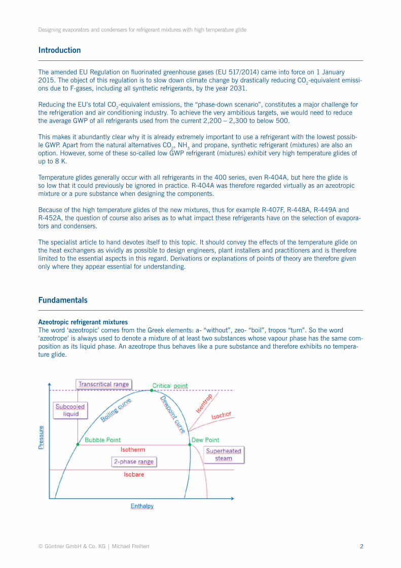
Azeotropic refrigerant mixturesThe word ‘azeotropic’ comes from the Greek elements: a- “without”, zeo- “boil”, tropos “turn”. So the word ‘azeotrope’ is always used to denote a mixture of at least two substances whose vapour phase has the same com-position as its liquid phase. An azeotrope thus behaves like a pure substance and therefore exhibits no tempera-ture glide.
Designing evaporators and condensers for refrigerant mixtures with high temperature glide
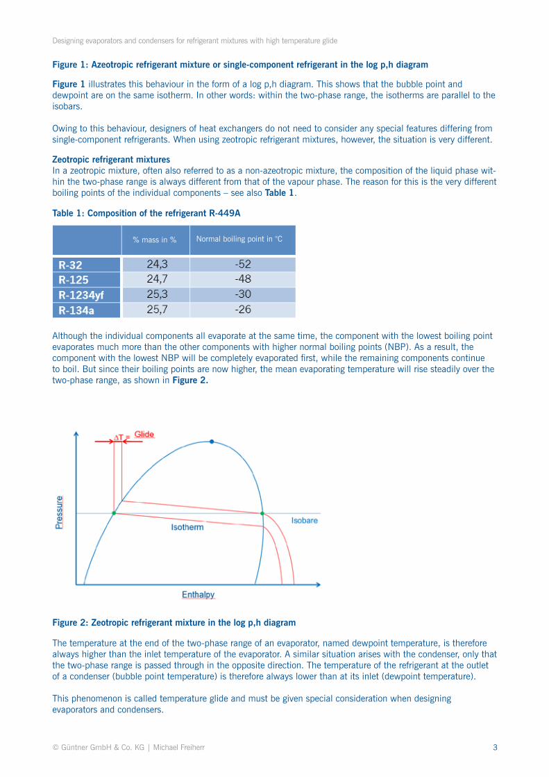
Zeotropic refrigerant mixturesIn a zeotropic mixture, often also referred to as a non-azeotropic mixture, the composition of the liquid phase wit-hin the two-phase range is always different from that of the vapour phase. The reason for this is the very different boiling points of the individual components – see also Table 1.
Although the individual components all evaporate at the same time, the component with the lowest boiling point evaporates much more than the other components with higher normal boiling points (NBP). As a result, the component with the lowest NBP will be completely evaporated first, while the remaining components continue to boil. But since their boiling points are now higher, the mean evaporating temperature will rise steadily over the two-phase range, as shown in Figure 2.
Table 1: Composition of the refrigerant R-449A
Figure 2: Zeotropic refrigerant mixture in the log p,h diagram
The temperature at the end of the two-phase range of an evaporator, named dewpoint temperature, is therefore always higher than the inlet temperature of the evaporator. A similar situation arises with the condenser, only that the two-phase range is passed through in the opposite direction. The temperature of the refrigerant at the outlet of a condenser (bubble point temperature) is therefore always lower than at its inlet (dewpoint temperature).
This phenomenon is called temperature glide and must be given special consideration when designing evaporators and condensers.
Figure 1 illustrates this behaviour in the form of a log p,h diagram. This shows that the bubble point and dewpoint are on the same isotherm. In other words: within the two-phase range, the isotherms are parallel to the isobars.
Owing to this behaviour, designers of heat exchangers do not need to consider any special features differing from single-component refrigerants. When using zeotropic refrigerant mixtures, however, the situation is very different.
Figure 1: Azeotropic refrigerant mixture or single-component refrigerant in the log p,h diagram
Designing evaporators and condensers for refrigerant mixtures with high temperature glide
Influence of temperature glide
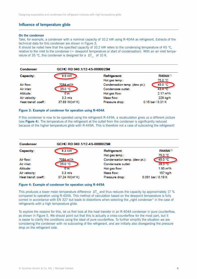
On the condenserTake, for example, a condenser with a nominal capacity of 10.2 kW using R-404A as refrigerant. Extracts of the technical data for this condenser are shown in Figure 3. It should be noted here that the specified capacity of 10.2 kW refers to the condensing temperature of 45 °C, relative to the inlet to the condenser (= dewpoint temperature or start of condensation). With an air inlet tempe-rature of 35 °C, this condenser is designed for a 〖∆TL1 of 10 K.
Figure 3: Example of condenser for operation using R-404A
Figure 4: Example of condenser for operation using R-449A
If this condenser is now to be operated using the refrigerant R-449A, a recalculation gives us a different picture (see Figure 4). The temperature of the refrigerant at the outlet from the condenser is significantly reduced because of the higher temperature glide with R-449A. This is therefore not a case of subcooling the refrigerant!
This produces a lower mean temperature difference 〖ΔTm and thus reduces the capacity by approximately 17 % compared to operation using R-404A. This method of calculation based on the dewpoint temperature is fully correct in accordance with EN 327 but leads to distortions when selecting the „right condenser“ in the case of refrigerants with a high temperature glide.
To explore the reasons for this, let us first look at the heat transfer in an R-404A condenser in pure counterflow, as shown in Figure 5. We should point out that this is actually a cross-counterflow for the most part, but it is easier to clarify the conditions using the ideal of pure counterflow. To further simplify the situation we are considering the condenser with no subcooling of the refrigerant, and are initially also disregarding the pressure drop on the refrigerant side.
Designing evaporators and condensers for refrigerant mixtures with high temperature glide
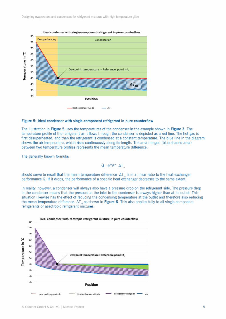
Figure 5: Ideal condenser with single-component refrigerant in pure counterflow
The illustration in Figure 5 uses the temperatures of the condenser in the example shown in Figure 3. The temperature profile of the refrigerant as it flows through the condenser is depicted as a red line. The hot gas is first desuperheated, and then the refrigerant is condensed at a constant temperature. The blue line in the diagram shows the air temperature, which rises continuously along its length. The area integral (blue shaded area) between two temperature profiles represents the mean temperature difference.
The generally known formula:
Q〖=k*A* 〖ΔTm
should serve to recall that the mean temperature difference 〖ΔTm is in a linear ratio to the heat exchanger performance Q. If it drops, the performance of a specific heat exchanger decreases to the same extent.
In reality, however, a condenser will always also have a pressure drop on the refrigerant side. The pressure drop in the condenser means that the pressure at the inlet to the condenser is always higher than at its outlet. This situation likewise has the effect of reducing the condensing temperature at the outlet and therefore also reducing the mean temperature difference 〖ΔTm as shown in Figure 6. This also applies fully to all single-component refrigerants or azeotropic refrigerant mixtures.
⋅
⋅
VerflüssigungEnthitzung
Taupunkt-Temperatur = Bezugspunkt = tc
Δ𝑇𝑚
30
35
40
45
50
55
60
65
70
75
80
Tem
pera
ture
in °C
Position
Idealer Verflüssiger mit Einstoff-Kältemittel im reinen Gegenstrom
Wärmeübertrager ohne dp Luft
Desuperheating Condensation
Dewpoint temperature = Reference point = tc
Heat exchanger w/o dp Air
Taupunkt-Temperatur = Bezugspunkt = tc
30
35
40
45
50
55
60
65
70
75
80
Tem
pera
ture
in °C
Position
Real condenser with zeotropic refrigerant mixture in pure counterflow
Wärmeübertrager ohne dp Wärmeübertrager mit dp Kältemittel mit Gleit Luft
Dewpoint temperature = Reference point = tc
Heat exchanger w/o dp Heat exchanger with dp Refrigerant with glide Air
Designing evaporators and condensers for refrigerant mixtures with high temperature glide
Figure 6: Real condenser with zeotropic refrigerant mixture in pure counterflow
Lowering the refrigerant outlet temperature by 0.5 K reduces the mean temperature difference by around 2 %. While this effect can be ignored in practice or taken into account by thermodynamic calculation-based selection software, it does clarify the effect of a dropping condensing temperature at the condenser outlet.
This is because the effect of a temperature glide in zeotropic refrigerant mixtures is similar to that of a pressure drop in the condenser, since, as illustrated in Figure 2, the boiling temperature is always lower than the dewpoint. This means that the mean temperature difference (Figure 6, light green area) is further reduced by the temperature glide of the refrigerant. The remaining and effectively usable temperature difference following deduction of all losses for heat transfer is represented by the purple shaded area.
Interim conclusion:
The temperature glide of zeotropic refrigerant mixtures results in smaller temperature differences at the condenser. The condenser performance decreases.
In designs based on the dewpoint temperature, the condensers must be larger compared to refrigerants without temperature glide.
This ultimately leads, however, to lower condensing pressures, which can have a positive impact on the efficiency of the overall refrigerating installation.
Designing evaporators and condensers for refrigerant mixtures with high temperature glide
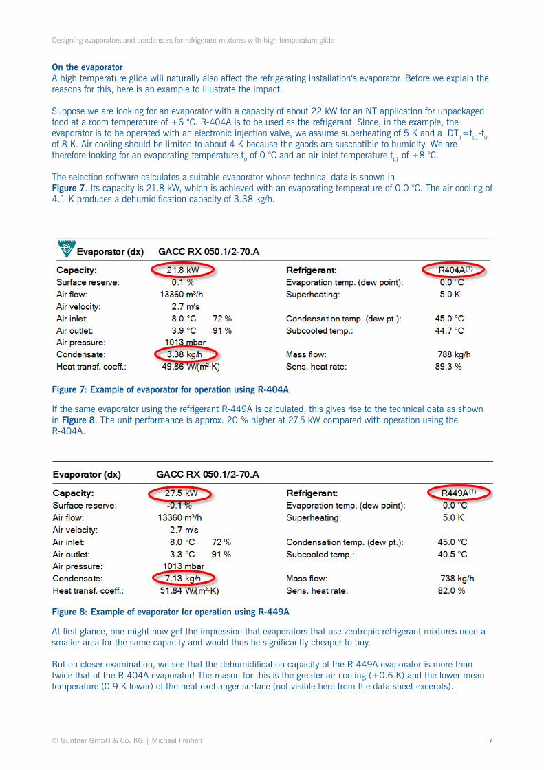
Figure 7: Example of evaporator for operation using R-404A
Figure 8: Example of evaporator for operation using R-449A
If the same evaporator using the refrigerant R-449A is calculated, this gives rise to the technical data as shown in Figure 8. The unit performance is approx. 20 % higher at 27.5 kW compared with operation using the R-404A.
At first glance, one might now get the impression that evaporators that use zeotropic refrigerant mixtures need a smaller area for the same capacity and would thus be significantly cheaper to buy.
But on closer examination, we see that the dehumidification capacity of the R-449A evaporator is more than twice that of the R-404A evaporator! The reason for this is the greater air cooling (+0.6 K) and the lower mean temperature (0.9 K lower) of the heat exchanger surface (not visible here from the data sheet excerpts).
On the evaporatorA high temperature glide will naturally also affect the refrigerating installation‘s evaporator. Before we explain the reasons for this, here is an example to illustrate the impact.
Suppose we are looking for an evaporator with a capacity of about 22 kW for an NT application for unpackaged food at a room temperature of +6 °C. R-404A is to be used as the refrigerant. Since, in the example, the evaporator is to be operated with an electronic injection valve, we assume superheating of 5 K and a 〖DT1=tL1-t0 of 8 K. Air cooling should be limited to about 4 K because the goods are susceptible to humidity. We are therefore looking for an evaporating temperature t0 of 0 °C and an air inlet temperature tL1 of +8 °C.
The selection software calculates a suitable evaporator whose technical data is shown inFigure 7. Its capacity is 21.8 kW, which is achieved with an evaporating temperature of 0.0 °C. The air cooling of 4.1 K produces a dehumidification capacity of 3.38 kg/h.
Designing evaporators and condensers for refrigerant mixtures with high temperature glide
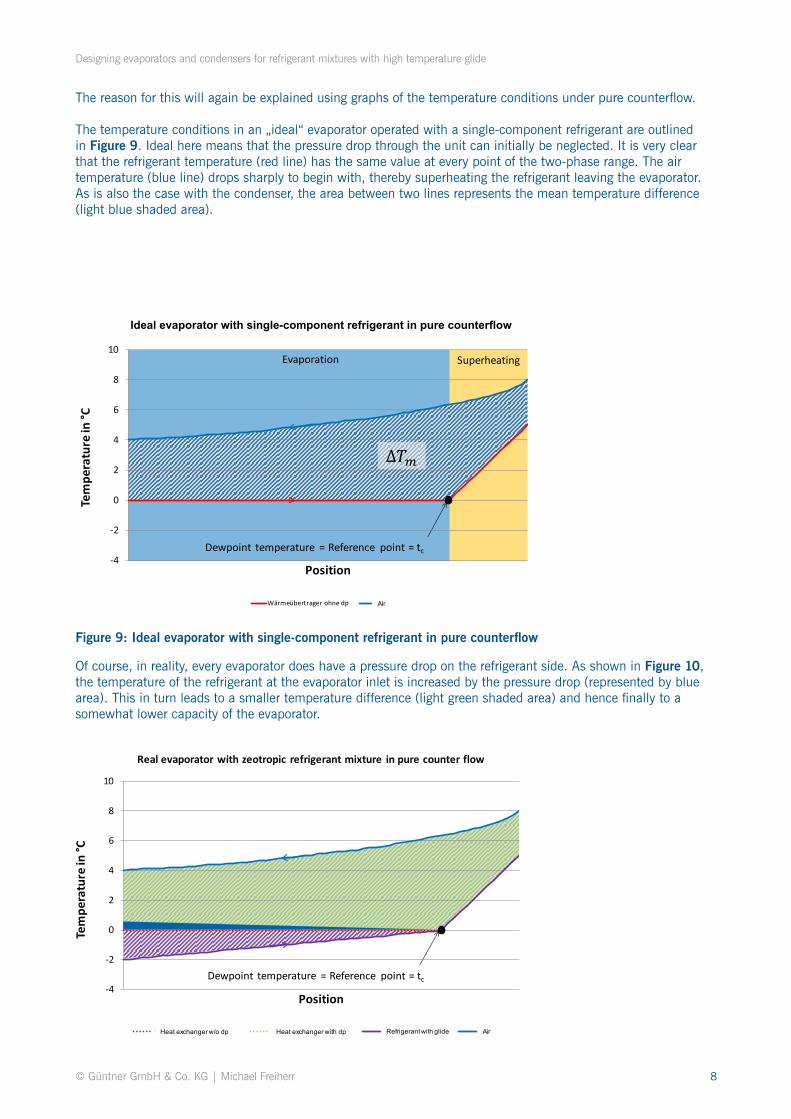
The reason for this will again be explained using graphs of the temperature conditions under pure counterflow.
The temperature conditions in an „ideal“ evaporator operated with a single-component refrigerant are outlined in Figure 9. Ideal here means that the pressure drop through the unit can initially be neglected. It is very clear that the refrigerant temperature (red line) has the same value at every point of the two-phase range. The air temperature (blue line) drops sharply to begin with, thereby superheating the refrigerant leaving the evaporator. As is also the case with the condenser, the area between two lines represents the mean temperature difference (light blue shaded area).
Figure 9: Ideal evaporator with single-component refrigerant in pure counterflow
Of course, in reality, every evaporator does have a pressure drop on the refrigerant side. As shown in Figure 10, the temperature of the refrigerant at the evaporator inlet is increased by the pressure drop (represented by blue area). This in turn leads to a smaller temperature difference (light green shaded area) and hence finally to a somewhat lower capacity of the evaporator.
ÜberhitzungVerdampfung
Taupunkt-Temperatur = Bezugspunkt = t0
Δ𝑇𝑚
-4
-2
0
2
4
6
8
10
Tem
pera
ture
in °C
Position
Wärmeübertrager ohne dp Luft
Evaporation Superheating
Dewpoint temperature = Reference point = tc
LuftAir
Taupunkt-Temperatur = Bezugspunkt = t0-4
-2
0
2
4
6
8
10
Tem
pera
ture
in °C
Position
Real evaporator with zeotropic refrigerant mixture in pure counter flow
Wärmeübertrager ohne dp Wärmeübertrager mit dp Kältemittel mit Gleit Luft
Dewpoint temperature = Reference point = tc
Heat exchanger with dp Refrigerant with glide AirHeat exchanger w/o dp
Ideal evaporator with single-component refrigerant in pure counterflow
Designing evaporators and condensers for refrigerant mixtures with high temperature glide
Figure 10: Real evaporator with zeotropic refrigerant mixture in pure counterflow
If the condenser is now operated with a zeotropic refrigerant mixture, the inlet temperature of the refrigerant reduces significantly compared with the design based on a single-component refrigerant since – depending on the norm – the dewpoint temperature is critical for the design of the evaporator and is therefore kept constant. The refrigerant must therefore enter the evaporator at a lower temperature if the dewpoint temperature is to remain constant.
This lower inlet temperature leads on one hand to an additionally usable temperature difference (purple shaded area), resulting in a greater evaporator capacity, but on the other hand also results in a lower surface temperature, which in turn causes higher dehumidification of the cold room air and not least the actual refrigerated goods.
Interim conclusion:
The temperature glide of zeotropic refrigerant mixtures results in greater temperature differences at the evaporator. The evaporator performance increases.
In designs based on the dewpoint temperature, the evaporators are smaller compared to refrigerants without temperature glide.
However, this results in greater air cooling in operation as well as lower surface temperatures, which in turn leads to higher dehumidification of the cold room air.
This effect has a particularly negative impact on the quality of unpackaged refrigerated goods susceptible to humidity in the normal refrigeration range.
Designing evaporators and condensers for refrigerant mixtures with high temperature glide
Figure 11: Condenser design with mean temperature in the log p,h diagram
Calculating using the mean temperature
To practically negate the effects of the temperature glide on the heat exchanger, condensers and evaporators should be selected based on the mean temperature method. The next section explains what the mean tempera-ture is and the results delivered by this method.
CondenserThe mean temperature for a condenser is the arithmetic mean of the boiling temperature and dewpoint temperature.
The light grey dashed profile depicted in Figure 11 shows the circuit with a condenser designed based on the dewpoint temperature. The black line represents a condenser with mean temperature design. The dewpoint tem-perature of the condenser depicted by the light grey dashed line (e.g. 45 °C) now becomes the mean temperature of the condenser depicted by a black line.
It can be seen that the condensing pressure and therefore the dewpoint temperature corresponding to the mean temperature must be accordingly higher. The difference between two temperatures is therefore dependent on the temperature glide of the respective refrigerant and the operating pressure. The specific thermophysical properties of the respective refrigerant under examination must therefore be the basis for all further calculations.
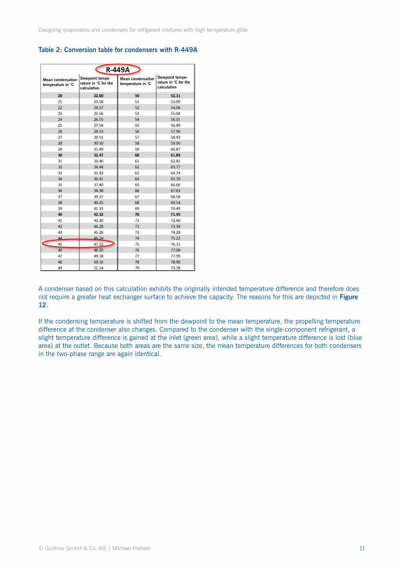
If the manufacturer‘s selection software does not support calculation based on the mean temperature in any case, the dewpoint temperature corresponding to the mean temperature must be entered in the calculation program as the condensation temperature in order to still be able to calculate the condenser based on the mean temperature. The conversion data for the refrigerant mixture R-449A is depicted in Table 2 by way of example. A dewpoint temperature of 47.22 °C would therefore have to be assumed for a mean condensing temperature of 45 °C.
Designing evaporators and condensers for refrigerant mixtures with high temperature glide
Table 2: Conversion table for condensers with R-449A
A condenser based on this calculation exhibits the originally intended temperature difference and therefore does not require a greater heat exchanger surface to achieve the capacity. The reasons for this are depicted in Figure 12.
If the condensing temperature is shifted from the dewpoint to the mean temperature, the propelling temperature difference at the condenser also changes. Compared to the condenser with the single-component refrigerant, a slight temperature difference is gained at the inlet (green area), while a slight temperature difference is lost (blue area) at the outlet. Because both areas are the same size, the mean temperature differences for both condensers in the two-phase range are again identical.
Designing evaporators and condensers for refrigerant mixtures with high temperature glide
Figure 12: Temperature conditions at the condenser with mean temperature calculation
Owing to the slightly higher dewpoint temperature, the hot gas must, however, enter the condenser at a higher temperature level. This leads once more to a higher temperature difference (yellow area) compared with the dewpoint design. The condensers will therefore always exhibit slightly better capacities with this method compared with traditionally calculated condensers with single-component refrigerants.
EvaporatorDetermining the mean temperature when designing an evaporator is a bit more complicated than for the con-denser. Reducing the refrigerant upstream of the evaporator has the effect that it is already within the two-phase range when it enters the evaporator. In this case, we can no longer simply calculate the mean temperature as the arithmetic mean of the boiling temperature and dewpoint temperature, rather it must be determined in an iterati-ve process. The pressure and dewpoint temperature increase, however, as shown in Figure 13.
Mittelpunkt-Temperatur = Bezugspunkt = tc
30
35
40
45
50
55
60
65
70
75
80
Tem
pera
ture
in °C
Position
Condenser with mean temperature design
Wärmeübertrager ohne dp Wärmeübertrager mit dp Kältemittel mit Gleit
Luft Gleit und Mitteltemp
Midpoint temperature = Reference point = tc
Heat exchanger w/o dp Heat exchanger with dp Refrigerant with glide
Designing evaporators and condensers for refrigerant mixtures with high temperature glide
Figure 13: Evaporator design with mean temperature in the log p,h diagram
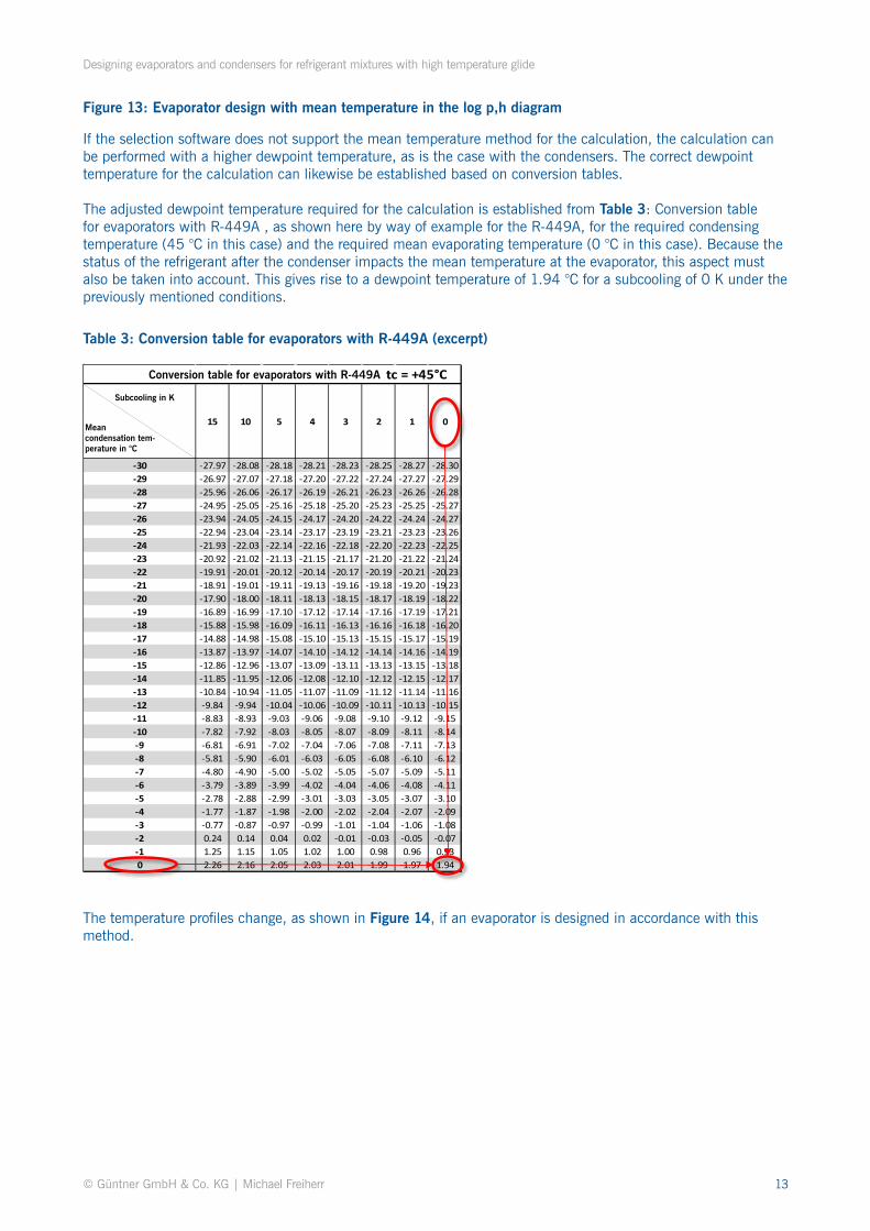
Table 3: Conversion table for evaporators with R-449A (excerpt)
If the selection software does not support the mean temperature method for the calculation, the calculation can be performed with a higher dewpoint temperature, as is the case with the condensers. The correct dewpoint temperature for the calculation can likewise be established based on conversion tables.
The adjusted dewpoint temperature required for the calculation is established from Table 3: Conversion table for evaporators with R-449A , as shown here by way of example for the R-449A, for the required condensing temperature (45 °C in this case) and the required mean evaporating temperature (0 °C in this case). Because the status of the refrigerant after the condenser impacts the mean temperature at the evaporator, this aspect must also be taken into account. This gives rise to a dewpoint temperature of 1.94 °C for a subcooling of 0 K under the previously mentioned conditions.
The temperature profiles change, as shown in Figure 14, if an evaporator is designed in accordance with this method.
Unter- kühlung in KmittlereVerdampfungs-Temperatur in °C
Designing evaporators and condensers for refrigerant mixtures with high temperature glide
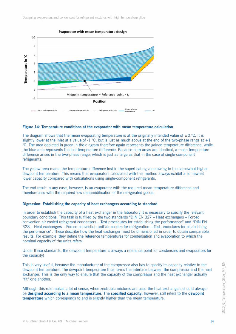
Figure 14: Temperature conditions at the evaporator with mean temperature calculation
Digression: Establishing the capacity of heat exchangers according to standard
The diagram shows that the mean evaporating temperature is at the originally intended value of ±0 °C. It is slightly lower at the inlet at a value of -1 °C, but is just as much above at the end of the two-phase range at +1 °C. The area depicted in green in the diagram therefore again represents the gained temperature difference, while the blue area represents the lost temperature difference. Because both areas are identical, a mean temperature difference arises in the two-phase range, which is just as large as that in the case of single-component refrigerants.
The yellow area marks the temperature difference lost in the superheating zone owing to the somewhat higher dewpoint temperature. This means that evaporators calculated with this method always exhibit a somewhat lower capacity compared with calculations using single-component refrigerants.
The end result in any case, however, is an evaporator with the required mean temperature difference and therefore also with the required low dehumidification of the refrigerated goods.
In order to establish the capacity of a heat exchanger in the laboratory it is necessary to specify the relevant boundary conditions. This task is fulfilled by the two standards “DIN EN 327 – Heat exchangers – Forced convection air cooled refrigerant condensers – Test procedures for establishing the performance” and “DIN EN 328 – Heat exchangers – Forced convection unit air coolers for refrigeration – Test procedures for establishing the performance”. These describe how the heat exchanger must be dimensioned in order to obtain comparable results. For example, they define the reference temperatures for condensation and evaporation to which the nominal capacity of the units refers.
Under these standards, the dewpoint temperature is always a reference point for condensers and evaporators for the capacity!
This is very useful, because the manufacturer of the compressor also has to specify its capacity relative to the dewpoint temperature. The dewpoint temperature thus forms the interface between the compressor and the heat exchanger. This is the only way to ensure that the capacity of the compressor and the heat exchanger actually “fit” one another.
Although this rule makes a lot of sense, when zeotropic mixtures are used the heat exchangers should always be designed according to a mean temperature. The specified capacity, however, still refers to the dewpoint temperature which corresponds to and is slightly higher than the mean temperature.
Mittelpunkt-Temperatur = Bezugspunkt = t0-4
-2
0
2
4
6
8
10
Tem
pera
ture
in °C
Position
Evaporator with mean temperature design
Wärmeübertrager ohne dp Wärmeübertrager mit dp Kältemittel mit Gleit Gleit und Mitteltemp Luft
Midpoint temperature = Reference point = tc
Heat exchanger w/o dp Heat exchanger with dp Refrigerant with glide Gl ide and mean temperature