DFI Melbourne 2017. Designing piles for seismic events. H.G. Poulos 1 Designing Piles for Seismic Events H G Poulos Coffey Services Australia & University of Sydney Keywords: buckling; design; earthquakes; lateral response; liquefaction; pile; remedial methods ABSTRACT This paper sets out a simplified approach by which the practical foundation designer can undertake the relevant calculations to satisfy the requirements for deep foundation design in seismic areas. The following matters are dealt with: a. Design issues that should be addressed; b. Pile design for axial loading, including the possible effects of liquefaction; c. Pile design for lateral loading where liquefaction does not occur; d. Pile design for lateral loading where liquefaction does occur; e. Measures to mitigate against liquefaction effects. The paper is a modified version of a paper presented in 2013 to the 19 th NZGS Geotechnical Symposium, Queenstown, New Zealand. 1. INTRODUCTION Consideration of the effects of earthquakes and seismic loadings is an increasingly important aspect of modern foundation design, and most contemporary standards have a mandatory requirement for such consideration. For example, the Australian Piling Code, AS 2159-2009, states that “a pile shall be designed for adequate strength, stiffness and ductility under load combinations including earthquake design actions”. However, the methods by which such considerations can be undertaken are generally not set out in the standards, and many approaches have been utilized, ranging from very simplistic methods to extremely complex computer analyses. Accordingly, there appears to be scope for an approach that is soundly based but which is neither too simplistic nor too complex. Poulos (1989) has suggested that there are three categories of analysis and design, as follows: 1. Category 1: empirical methods. 2. Category 2: simplified but soundly-based methods. 3. Category 3: more comprehensive methods that are soundly-based, and site-specific. The objective of this paper is to set out a systematic but simplified approach which falls into Category 2 above, and by which the foundation designer can undertake the relevant analyses to satisfy the foundation design requirements for seismic regions. Emphasis is placed on methods that do not require “black box” software or which employ complex soil models in which the physical meaning of the parameters is unclear.
Transcript
DFI Melbourne 2017. Designing piles for seismic events. H.G. Poulos
This paper sets out a simplified approach by which the practical foundation designer canundertake the relevant calculations to satisfy the requirements for deep foundation design inseismic areas. The following matters are dealt with:
a. Design issues that should be addressed;b. Pile design for axial loading, including the possible effects of liquefaction;c. Pile design for lateral loading where liquefaction does not occur;d. Pile design for lateral loading where liquefaction does occur;e. Measures to mitigate against liquefaction effects.
The paper is a modified version of a paper presented in 2013 to the 19th NZGS GeotechnicalSymposium, Queenstown, New Zealand.
1. INTRODUCTION
Consideration of the effects of earthquakes and seismic loadings is an increasingly importantaspect of modern foundation design, and most contemporary standards have a mandatoryrequirement for such consideration. For example, the Australian Piling Code, AS 2159-2009,states that “a pile shall be designed for adequate strength, stiffness and ductility under loadcombinations including earthquake design actions”. However, the methods by which suchconsiderations can be undertaken are generally not set out in the standards, and many approacheshave been utilized, ranging from very simplistic methods to extremely complex computeranalyses. Accordingly, there appears to be scope for an approach that is soundly based but whichis neither too simplistic nor too complex.
Poulos (1989) has suggested that there are three categories of analysis and design, as follows:
1. Category 1: empirical methods.2. Category 2: simplified but soundly-based methods.3. Category 3: more comprehensive methods that are soundly-based, and site-specific.
The objective of this paper is to set out a systematic but simplified approach which falls intoCategory 2 above, and by which the foundation designer can undertake the relevant analyses tosatisfy the foundation design requirements for seismic regions. Emphasis is placed on methodsthat do not require “black box” software or which employ complex soil models in which thephysical meaning of the parameters is unclear.
DFI Melbourne 2017. Designing piles for seismic events. H.G. Poulos
2
2. DESIGN ISSUES
In addition to the conventional design issues of axial load capacity, settlement, structuraladequacy and durability under static imposed loadings, the design of deep foundations in seismicareas requires consideration of the following factors:
1. The effects of earthquake excitation on the axial load capacity of the foundationsystem;
2. The effects of earthquake excitation on the lateral response and the structural integrityof the foundation system.
In both cases, the possible loss of soil support during the earthquake due to liquefaction or partialloss of soil strength must be considered. Both the geotechnical and the structural strength of thefoundations can be compromised by the earthquake effects, and so each has to be examined inturn.
For assessment of the response of the foundation during a seismic event, it is also necessary toestimate the stiffness and damping of the foundation system, since the foundation response caninfluence the natural period of the supported structure.
3. EFFECTS OF EARTHQUAKES ON FOUNDATION SOILS
Soil deposits at a site subjected to an earthquake may experience the following effects:• Increases in pore pressure within the soils;• Time-dependent vertical ground movements during and after the earthquake;• Time-dependent lateral ground movements during the earthquake.
In foundation design, consideration must therefore be given to possible reductions in soil strengtharising from the build-up of excess pore pressures during and after the earthquake. In extremecases, the generation of pore pressures may lead to liquefaction in relatively loose sandy and siltysoils.
As a consequence of the earthquake-induced ground movements, piles and other deep foundationswill be subjected to two sources of additional lateral loading:
a. Inertial loadings – these are forces that are induced in the piles because of theaccelerations generated within the structure by the earthquake. Consideration isgenerally confined to lateral inertial forces and moments, which are assumed to beapplied at the pile heads.
b. Kinematic loadings – these are forces and bending moments that are induced in thepiles because of the ground movements that results from the earthquake. Suchmovements will interact with the piles and because of the difference in stiffness ofthe piles and the moving soil, there will be lateral stresses developed between the pileand the soil, resulting in the development of shear forces and bending moments in thepiles. These actions will be time-dependent and need to be considered in the structuraldesign of the piles.
Thus, in addition to the usual design considerations for static loading, the above factors of strengthreduction, inertial loadings, and kinematic loadings, need to be incorporated into the designprocess.
When considering both the strength and stiffness of soils, consideration should also be given tothe effects of the high rate of loading that occur during a seismic event. Such loading rate effectstend to increase both the strength and stiffness of soils, especially clay soils.
DFI Melbourne 2017. Designing piles for seismic events. H.G. Poulos
3
Appropriate assessment of the geotechnical parameters is a critical component of geotechnicaldesign for seismic actions, as it is for other types of imposed loadings. This issue is howeveroutside the scope of the present paper, and reference should be made to references such as Kramer(1996) who discusses such issues as the effects of strain, cyclic loading and loading rate effects.
3.1 Earthquake Characteristics Required for Foundation Design
Seismic design of foundations requires information on a number of characteristics of theanticipated earthquakes at the site, including the following:
• Earthquake size or magnitude;• Seismicity rate;• Maximum bedrock acceleration, and it attenuation with distance from the causative
fault;• The duration;• The predominant period;• Representative time-acceleration relationships at bedrock level.
More details of these and other earthquake characteristics can be found in Kramer (1996).However, interaction with seismologists is highly desirable in making the above assessments fora specific site or area.
4. PILE DESIGN FOR AXIAL LOADING
4.1 Without Liquefaction
In soils that are assessed to be non-liquefiable, the conventional methods may be adopted to assessthe ultimate shaft friction and end bearing capacity of the piles, including the possible effects ofgroup action.
Only limited attention has been paid to the axial response of piles during and after an earthquake.Poulos (1993) has provided an example of a pile in clay subjected to earthquake action. Thegeneration of excess pore pressures, and the consequent loss of strength of the clay, has beenincorporated into the analysis. The main conclusions drawn from this study are as follows:
1. Earthquakes with a Richter Magnitude in excess of about 6 have the potential to generatesignificant excess pore pressures in the clay, causing subsequent consolidation settlement.
2. The rate of development of these settlements is similar to that obtained from Terzaghi’sconsolidation theory, using the coefficient of consolidation for the soil in an over-consolidated state.
3. Piles in clay may be subjected to a short-term loss of axial capacity due to the “softening”of the surrounding soil arising from pore pressure build-up.
4. Piles may also experience a long-term increase in settlement and axial force, due to theground settlements induced by the earthquake.
4.2 Effects of Liquefaction
If liquefaction is assessed to be likely to occur within soils supporting a piled foundation, someof the issues that require consideration are as follows:
(a) Seismic excitation will cause settlements as well as lateral ground movements and thusthere will be a tendency for the development of negative skin friction on those parts ofthe pile which tend to settle less than the soil.
(b) There will tend to be a substantial reduction in effective stress in the soil due to thegeneration of excess pore pressures, and this will lead to a reduction in the lateral effective
DFI Melbourne 2017. Designing piles for seismic events. H.G. Poulos
4
stress between the pile and the soil, and a consequent reduction in the ultimate shaftfriction. This will reduce the axial capacity of the pile and the factor of safety againstgeotechnical pile failure. This reduction of capacity is however temporary and the initialshaft resistance should be largely re-instated after the excess pore pressures havedissipated.
To avoid temporary failure, a check should be made of the ultimate axial capacity of the pile,excluding any resistance from the liquefiable layers. Ideally, this reduced capacity should exceedthe design axial load that is likely to be applied to the pile during the earthquake by a suitablefactor of safety, for example, 1.25.
An additional mode of failure, buckling of the pile, may be initiated. This matter is discussedfurther below.
4.3 Pile Buckling
Bhattacharya and Bolton (2004) have identified another mechanism of axial failure of piles inliquefiable soils, namely buckling under axial loading due to loss of lateral support. Thismechanism is generally overlooked in design, yet can be an important contributor to foundationfailure. They emphasize that buckling of a pile is an unstable and destructive failure mechanism,whereas pile bending is a more stable mechanism. Pile buckling is a possible mechanism if thefollowing conditions exist:
• The pile is end bearing and socketed into rock;• The pile is carrying a relatively large axial load compared to the Euler buckling load
of an equivalent column.
Madabhushi and May (2009) recommend that the pile design process should incorporate thefollowing considerations:
• The ratio of the axial load to the Euler buckling load should be limited to about 1/5to provide a safety margin on buckling;
• The slenderness ratio of the piles, SR = L/(I/A) 0.5 (where L=effective pile lengthwithin the liquefiable layer, I = minimum moment of inertia, A = pile cross-sectionalarea), in the buckling zone should be no greater than 50 to avoid buckling instability.
The Euler buckling load PE can be estimated as follows:
PE = π2 EI/Le2 (1)
where EI=flexural rigidity of the pileLe = equivalent length of pile.
The equivalent length Le depends on the end conditions of the pile. For the extreme case of a pilehead that is unrestrained against both translation and rotation, but with a fixed base, Le = 2Lo,where Lo = length of pile in liquefied soil, while for a pile head that is restrained against rotation,Le = Lo. Alternatively, estimates of the pile buckling load can be made using the resultssummarised by Poulos and Davis (1980).
5. PILE DESIGN FOR LATERAL LOADING – NO LIQUEFACTION
5.1 Assessment of Inertial Loadings
For geotechnical analysis, the inertial forces imposed on the foundation system by the structureare usually obtained by the structural designers. Broadly, the maximum lateral force on thestructure is generally estimated by multiplying the mass of the structure by the peak spectral
DFI Melbourne 2017. Designing piles for seismic events. H.G. Poulos
5
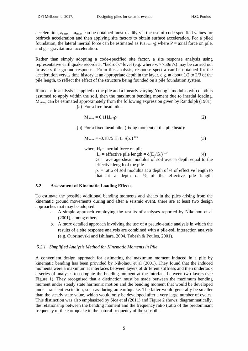
acceleration, asmax. asmax can be obtained most readily via the use of code-specified values forbedrock acceleration and then applying site factors to obtain surface acceleration. For a piledfoundation, the lateral inertial force can be estimated as P.asmax /g where P = axial force on pile,and g = gravitational acceleration.
Rather than simply adopting a code-specified site factor, a site response analysis usingrepresentative earthquake records at “bedrock” level (e.g. where vs> 750m/s) may be carried outto assess the ground response. From this analysis, response spectra can be obtained for theacceleration versus time history at an appropriate depth in the layer, e.g. at about 1/2 to 2/3 of thepile length, to reflect the effect of the structure being founded on a pile foundation system.
If an elastic analysis is applied to the pile and a linearly varying Young’s modulus with depth isassumed to apply within the soil, then the maximum bending moment due to inertial loading,Mimax, can be estimated approximately from the following expression given by Randolph (1981):
(a) For a free-head pile:
Mimax = 0.1HiLc/ρc (2)
(b) For a fixed head pile: (fixing moment at the pile head):
Mimax = -0.1875 Hi Lc /(ρc) 0.5 (3)
where Hi = inertial force on pileLc = effective pile length = d(Ep/Gc) 2/7 (4)
Gc = average shear modulus of soil over a depth equal to theeffective length of the pileρc = ratio of soil modulus at a depth of ¼ of effective length tothat at a depth of ½ of the effective pile length.
5.2 Assessment of Kinematic Loading Effects
To estimate the possible additional bending moments and shears in the piles arising from thekinematic ground movements during and after a seismic event, there are at least two designapproaches that may be adopted:
a. A simple approach employing the results of analyses reported by Nikolaou et al
(2001), among others
b. A more detailed approach involving the use of a pseudo-static analysis in which the
results of a site response analysis are combined with a pile-soil interaction analysis
(e.g. Cubrinovski and Ishihara, 2004, Tabesh & Poulos, 2001).
5.2.1 Simplified Analysis Method for Kinematic Moments in Pile
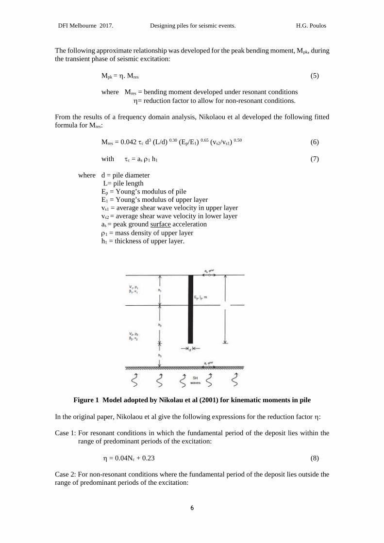
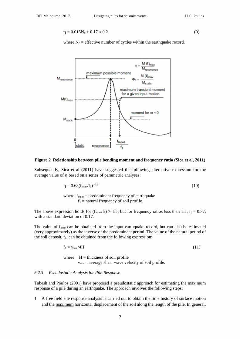
A convenient design approach for estimating the maximum moment induced in a pile bykinematic bending has been provided by Nikolaou et al (2001). They found that the inducedmoments were a maximum at interfaces between layers of different stiffness and then undertooka series of analyses to compute the bending moment at the interface between two layers (seeFigure 1). They recognised that a distinction must be made between the maximum bendingmoment under steady state harmonic motion and the bending moment that would be developedunder transient excitation, such as during an earthquake. The latter would generally be smallerthan the steady state value, which would only be developed after a very large number of cycles.This distinction was also emphasized by Sica et al (2011) and Figure 2 shows, diagrammatically,the relationship between the bending moment and the frequency ratio (ratio of the predominantfrequency of the earthquake to the natural frequency of the subsoil.
DFI Melbourne 2017. Designing piles for seismic events. H.G. Poulos
6
The following approximate relationship was developed for the peak bending moment, Mpk, duringthe transient phase of seismic excitation:
Mpk = η. Mres (5)
where Mres = bending moment developed under resonant conditionsη= reduction factor to allow for non-resonant conditions.
From the results of a frequency domain analysis, Nikolaou et al developed the following fittedformula for Mres:
Ep = Young’s modulus of pileE1 = Young’s modulus of upper layervs1 = average shear wave velocity in upper layervs2 = average shear wave velocity in lower layeras = peak ground surface accelerationρ1 = mass density of upper layerh1 = thickness of upper layer.
Figure 1 Model adopted by Nikolau et al (2001) for kinematic moments in pile
In the original paper, Nikolaou et al give the following expressions for the reduction factor η:
Case 1: For resonant conditions in which the fundamental period of the deposit lies within therange of predominant periods of the excitation:
η = 0.04Nc + 0.23 (8)
Case 2: For non-resonant conditions where the fundamental period of the deposit lies outside therange of predominant periods of the excitation:
DFI Melbourne 2017. Designing piles for seismic events. H.G. Poulos
7
η = 0.015Nc + 0.17 ≈ 0.2 (9)
where Nc = effective number of cycles within the earthquake record.
Figure 2 Relationship between pile bending moment and frequency ratio (Sica et al, 2011)
Subsequently, Sica et al (2011) have suggested the following alternative expression for theaverage value of η based on a series of parametric analyses:
η = 0.68(finput/f1) -1.5 (10)
where finput = predominant frequency of earthquakef1 = natural frequency of soil profile.
The above expression holds for (finput/f1) ≥ 1.5, but for frequency ratios less than 1.5, η = 0.37,with a standard deviation of 0.17.
The value of finput can be obtained from the input earthquake record, but can also be estimated(very approximately) as the inverse of the predominant period. The value of the natural period ofthe soil deposit, f1, can be obtained from the following expression:
f1 = vsav /4H (11)
where H = thickness of soil profilevsav = average shear wave velocity of soil profile.
5.2.3 Pseudostatic Analysis for Pile Response
Tabesh and Poulos (2001) have proposed a pseudostatic approach for estimating the maximumresponse of a pile during an earthquake. The approach involves the following steps:
1 A free field site response analysis is carried out to obtain the time history of surface motion
and the maximum horizontal displacement of the soil along the length of the pile. In general,
DFI Melbourne 2017. Designing piles for seismic events. H.G. Poulos
8
a one-dimensional analysis can be employed, using commercially available codes such as
SHAKE or DEEPSOIL, or else custom codes such as ERLS (Poulos, 1991).
2 The surface motion obtained in the above step is used in a spectral analysis of a single degree
of freedom system whose natural period is equal to that of the supported structure. The
spectral acceleration aspec is thus obtained.
3 A static analysis of the pile is carried out in which the pile is subjected simultaneously to the
application of the following loadings:
(i) A lateral force at the pile head equal to aspec.P, where P = vertical load acting
on pile head;
(ii) The maximum ground movements along the pile length, as obtained from
Step 1.
The analysis will give the maximum moment and shear force developed in the pile by thesimultaneous application of the inertial and kinematic loadings.
5.3 Combined Inertial and Kinematic Effects
The approach employed by Tabesh and Poulos (2001) may be conservative as the analysisimplicitly assumes that both the inertial and kinematic loadings are in phase. However, they havefound that this approach gives reasonable agreement with the results of a more complete dynamicanalysis, although it does tend to be conservative, and also good agreement is found when appliedto a case history in Japan.
A modification has been suggested by Tokimatsu et al (2005), using the following approach todeal with combined inertial and kinematic loadings:
• If the natural period of the superstructure is less than that of the ground, the kinematicforce tends to be in phase with the inertial force, increasing the stress in the piles. Themaximum pile stress occurs when both the inertial force and the grounddisplacements take the peak values and act in the same direction. In this case, themaximum moment is the sum of the values for inertial and kinematic effects.
• If the natural period of the superstructure is greater than that of the ground, thekinematic force tends to be out of phase with the inertial force. This restrains the pileforce, rather than increasing it. The maximum pile stress tends to occur when bothinertial force and ground displacement do not become maxima at the same time. Inthis case, the maximum moment is the square root of the sum of the squares of themoments due to each effect.
The moments via this approach have been found to be in good agreement with model tests, bothwith and without the effects of liquefaction.
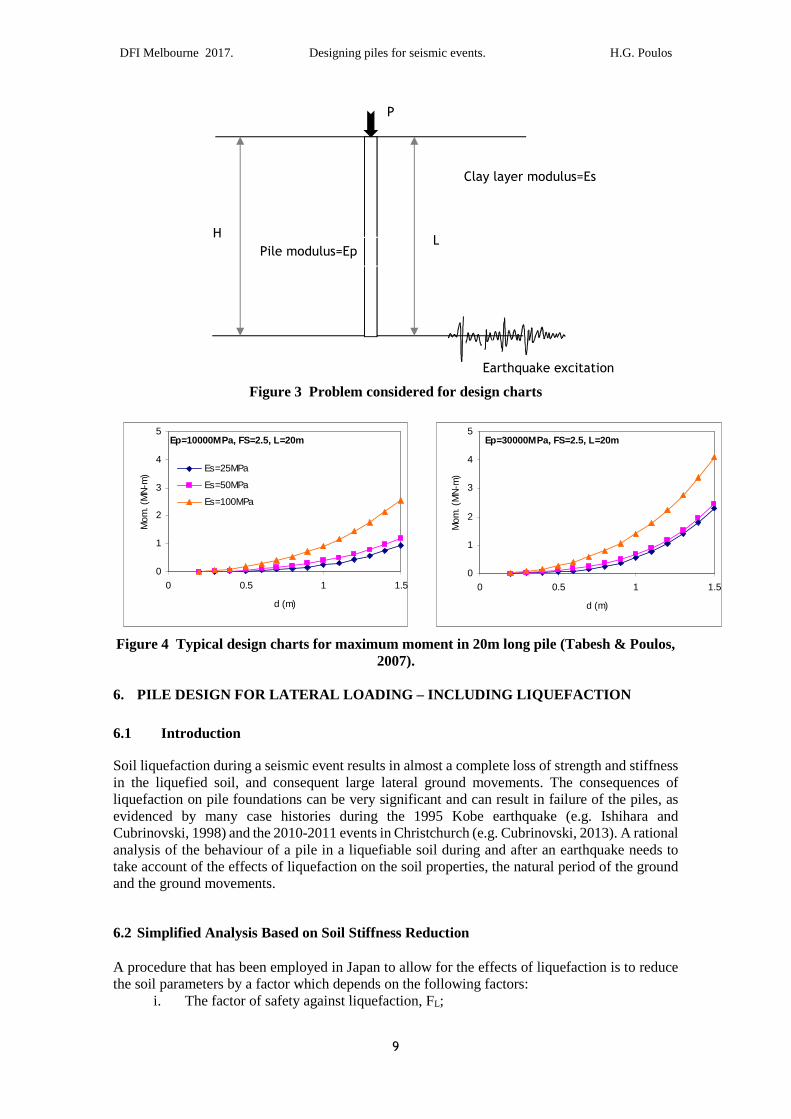
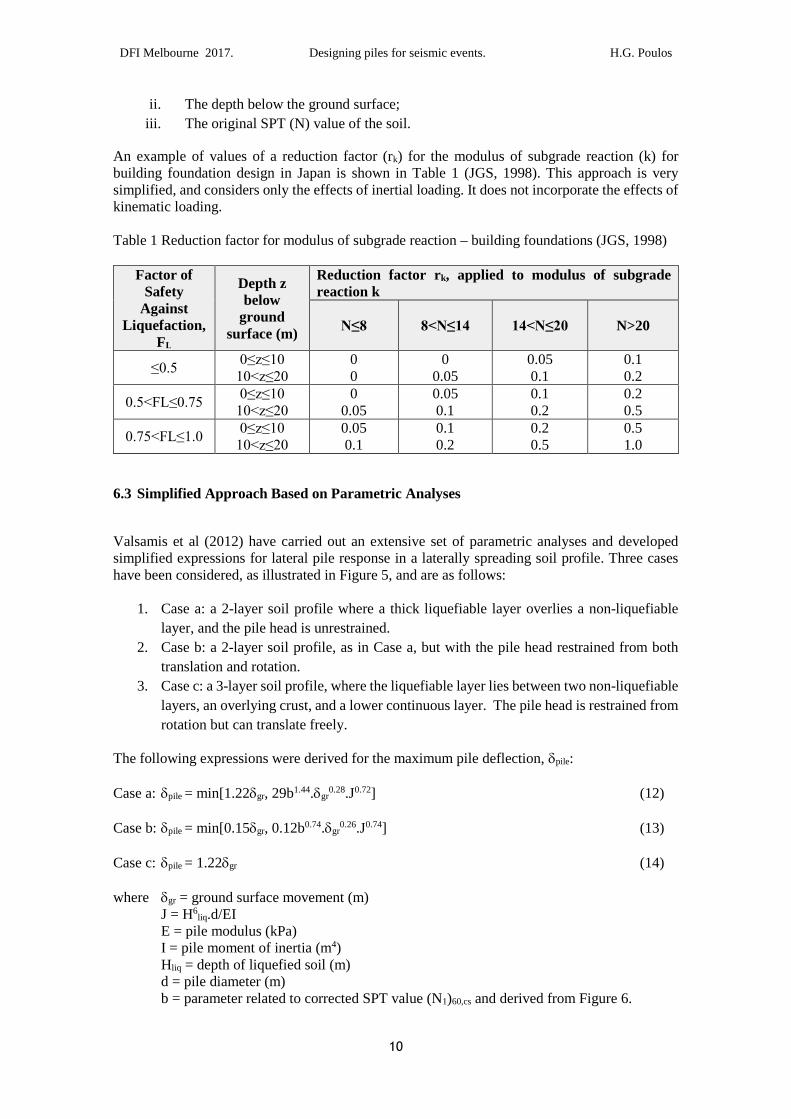
5.4 Design Charts
Using the pseudostatic approach, Tabesh and Poulos (2007) produced some simple design chartsfor piles within a uniform soil profile. Figure 3 shows the problem addressed and Figure 4 givesexamples of these charts for the case of a 20m long pile with a vertical load corresponding to afactor of safety of 2.5 against geotechnical failure. These charts are meant to provide only a verypreliminary estimate of lateral pile response.
DFI Melbourne 2017. Designing piles for seismic events. H.G. Poulos
Figure 4 Typi
6. PILE DESI
6.1 Introdu
Soil liquefactionin the liquefiedliquefaction onevidenced byCubrinovski, 19analysis of thetake account ofand the ground
6.2 Simplified
A procedure thathe soil paramet
i. The
P
Clay layer modulus=Es
Ep=1000
0
1
2
3
4
5
0
Mom
.(M
N-m
)
9
Figure 3 Problem considere
cal design charts for maximum mom2007).
GN FOR LATERAL LOADING –
ction
during a seismic event results in almsoil, and consequent large lateral
pile foundations can be very significamany case histories during the 1998) and the 2010-2011 events in Chrisbehaviour of a pile in a liquefiable sothe effects of liquefaction on the soilmovements.
Analysis Based on Soil Stiffness Red
t has been employed in Japan to allowers by a factor which depends on the ffactor of safety against liquefaction,
H
Pile modulus=Ep
0MPa, FS=2.5, L=20m
0.5 1 1.5
d (m)
Es=25MPa
Es=50MPa
Es=100MPa
d for de
ent in 2
INCLU
ost a comground mnt and c95 Kobtchurch (il duringpropertie
uction
for theollowinFL;
L
0
1
2
3
4
5
Mom
.(M
N-m
)
sign charts
0m long pile (Tabesh & Poulos,
DING LIQUEFACTION
plete loss of strength and stiffnessovements. The consequences of
an result in failure of the piles, ase earthquake (e.g. Ishihara ande.g. Cubrinovski, 2013). A rational
and after an earthquake needs tos, the natural period of the ground
effects of liquefaction is to reduceg factors:
Earthquake excitation
Ep=30000MPa, FS=2.5, L=20m
0 0.5 1 1.5
d (m)
DFI Melbourne 2017. Designing piles for seismic events. H.G. Poulos
10
ii. The depth below the ground surface;
iii. The original SPT (N) value of the soil.
An example of values of a reduction factor (rk) for the modulus of subgrade reaction (k) forbuilding foundation design in Japan is shown in Table 1 (JGS, 1998). This approach is verysimplified, and considers only the effects of inertial loading. It does not incorporate the effects ofkinematic loading.
Table 1 Reduction factor for modulus of subgrade reaction – building foundations (JGS, 1998)
Factor ofSafety
AgainstLiquefaction,
FL
Depth zbelow
groundsurface (m)
Reduction factor rk, applied to modulus of subgradereaction k
N≤8 8<N≤14 14<N≤20 N>20
≤0.5 0≤z≤10
10<z≤20 00
00.05
0.050.1
0.10.2
0.5<FL≤0.75 0≤z≤10
10<z≤20 0
0.050.050.1
0.10.2
0.20.5
0.75<FL≤1.0 0≤z≤10
10<z≤20 0.050.1
0.10.2
0.20.5
0.51.0
6.3 Simplified Approach Based on Parametric Analyses
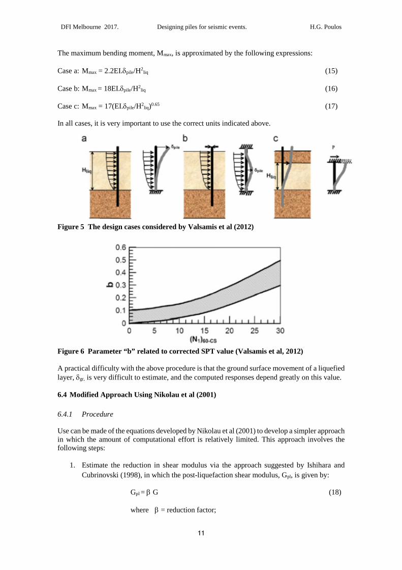
Valsamis et al (2012) have carried out an extensive set of parametric analyses and developedsimplified expressions for lateral pile response in a laterally spreading soil profile. Three caseshave been considered, as illustrated in Figure 5, and are as follows:
1. Case a: a 2-layer soil profile where a thick liquefiable layer overlies a non-liquefiable
layer, and the pile head is unrestrained.
2. Case b: a 2-layer soil profile, as in Case a, but with the pile head restrained from both
translation and rotation.
3. Case c: a 3-layer soil profile, where the liquefiable layer lies between two non-liquefiable
layers, an overlying crust, and a lower continuous layer. The pile head is restrained from
rotation but can translate freely.
The following expressions were derived for the maximum pile deflection, δpile:
Case a: δpile = min[1.22δgr, 29b1.44.δgr0.28.J0.72] (12)
Case b: δpile = min[0.15δgr, 0.12b0.74.δgr0.26.J0.74] (13)
Case c: δpile = 1.22δgr (14)
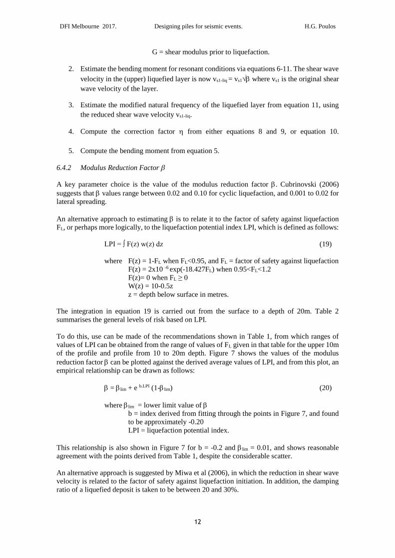
where δgr = ground surface movement (m)J = H6
liq.d/EIE = pile modulus (kPa)I = pile moment of inertia (m4)Hliq = depth of liquefied soil (m)d = pile diameter (m)b = parameter related to corrected SPT value (N1)60,cs and derived from Figure 6.
DFI Melbourne 2017. Designing piles for seismic events. H.G. Poulos
11
The maximum bending moment, Mmax, is approximated by the following expressions:
Case a: Mmax = 2.2EI.δpile/H2liq (15)
Case b: Mmax = 18EI.δpile/H2liq (16)
Case c: Mmax = 17(EI.δpile/H2liq)0.65 (17)
In all cases, it is very important to use the correct units indicated above.
Figure 5 The design cases considered by Valsamis et al (2012)
Figure 6 Parameter “b” related to corrected SPT value (Valsamis et al, 2012)
A practical difficulty with the above procedure is that the ground surface movement of a liquefiedlayer, δgr, is very difficult to estimate, and the computed responses depend greatly on this value.
6.4 Modified Approach Using Nikolau et al (2001)
6.4.1 Procedure
Use can be made of the equations developed by Nikolau et al (2001) to develop a simpler approachin which the amount of computational effort is relatively limited. This approach involves thefollowing steps:
1. Estimate the reduction in shear modulus via the approach suggested by Ishihara and
Cubrinovski (1998), in which the post-liquefaction shear modulus, Gpl, is given by:
Gpl = β G (18)
where β = reduction factor;
DFI Melbourne 2017. Designing piles for seismic events. H.G. Poulos
12
G = shear modulus prior to liquefaction.
2. Estimate the bending moment for resonant conditions via equations 6-11. The shear wave
velocity in the (upper) liquefied layer is now vs1-liq = vs1√β where vs1 is the original shear
wave velocity of the layer.
3. Estimate the modified natural frequency of the liquefied layer from equation 11, using
the reduced shear wave velocity vs1-liq.
4. Compute the correction factor η from either equations 8 and 9, or equation 10.
5. Compute the bending moment from equation 5.
6.4.2 Modulus Reduction Factor β
A key parameter choice is the value of the modulus reduction factor β. Cubrinovski (2006)suggests that β values range between 0.02 and 0.10 for cyclic liquefaction, and 0.001 to 0.02 forlateral spreading.
An alternative approach to estimating β is to relate it to the factor of safety against liquefactionFL, or perhaps more logically, to the liquefaction potential index LPI, which is defined as follows:
LPI = ∫ F(z) w(z) dz (19)
where F(z) = 1-FL when FL<0.95, and FL = factor of safety against liquefactionF(z) = 2x10 -6 exp(-18.427FL) when 0.95<FL<1.2F(z)= 0 when FL ≥ 0 W(z) = 10-0.5zz = depth below surface in metres.
The integration in equation 19 is carried out from the surface to a depth of 20m. Table 2summarises the general levels of risk based on LPI.
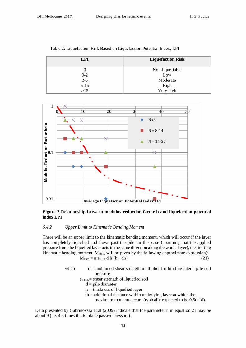
To do this, use can be made of the recommendations shown in Table 1, from which ranges ofvalues of LPI can be obtained from the range of values of FL given in that table for the upper 10mof the profile and profile from 10 to 20m depth. Figure 7 shows the values of the modulusreduction factor β can be plotted against the derived average values of LPI, and from this plot, anempirical relationship can be drawn as follows:
β = βlim + e b.LPI (1-βlim) (20)
where βlim = lower limit value of βb = index derived from fitting through the points in Figure 7, and foundto be approximately -0.20LPI = liquefaction potential index.
This relationship is also shown in Figure 7 for b = -0.2 and βlim = 0.01, and shows reasonableagreement with the points derived from Table 1, despite the considerable scatter.
An alternative approach is suggested by Miwa et al (2006), in which the reduction in shear wavevelocity is related to the factor of safety against liquefaction initiation. In addition, the dampingratio of a liquefied deposit is taken to be between 20 and 30%.
DFI Melbourne 2017. Designing piles for seismic events. H.G. Poulos
13
Table 2: Liquefaction Risk Based on Liquefaction Potential Index, LPI
LPI Liquefaction Risk
00-22-5
5-15>15
Non-liquefiableLow
ModerateHigh
Very high
Figure 7 Relationship between modulus reduction factor b and liquefaction potentialindex LPI
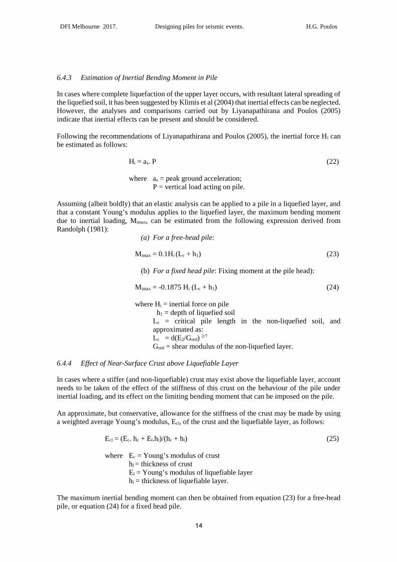
6.4.2 Upper Limit to Kinematic Bending Moment
There will be an upper limit to the kinematic bending moment, which will occur if the layerhas completely liquefied and flows past the pile. In this case (assuming that the appliedpressure from the liquefied layer acts in the same direction along the whole layer), the limitingkinematic bending moment, Mklim, will be given by the following approximate expression):
Mklim = n.su-Liq.d h1(h1+dh) (21)
where n = undrained shear strength multiplier for limiting lateral pile-soilpressure
su-Liq.= shear strength of liquefied soild = pile diameter
h1 = thickness of liquefied layerdh = additional distance within underlying layer at which the
maximum moment occurs (typically expected to be 0.5d-1d).
Data presented by Cubrinovski et al (2009) indicate that the parameter n in equation 21 may beabout 9 (i.e. 4.5 times the Rankine passive pressure).
0.01
0.1
1
0 10 20 30 40 50
Mo
du
lus
Re
du
ctio
nF
act
or
be
ta
Average Liquefaction Potential Index LPI
N<8
N = 8-14
N = 14-20
DFI Melbourne 2017. Designing piles for seismic events. H.G. Poulos
14
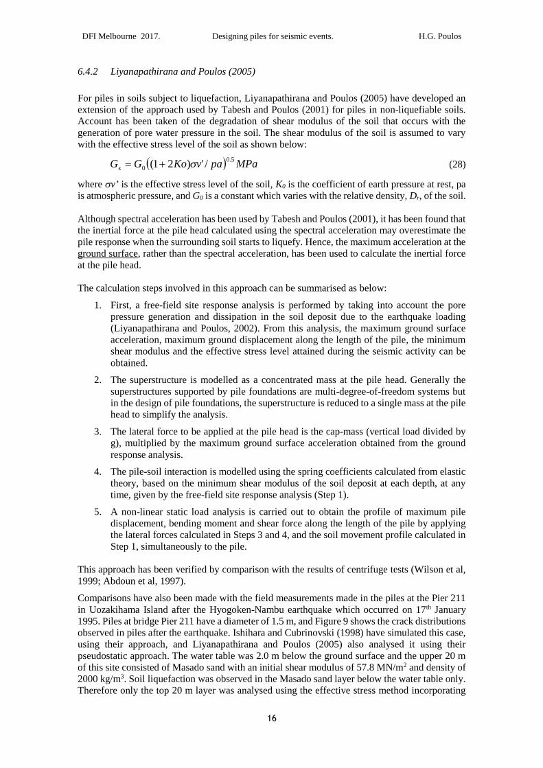
6.4.3 Estimation of Inertial Bending Moment in Pile
In cases where complete liquefaction of the upper layer occurs, with resultant lateral spreading ofthe liquefied soil, it has been suggested by Klimis et al (2004) that inertial effects can be neglected.However, the analyses and comparisons carried out by Liyanapathirana and Poulos (2005)indicate that inertial effects can be present and should be considered.
Following the recommendations of Liyanapathirana and Poulos (2005), the inertial force Hi canbe estimated as follows:
Hi = as. P (22)
where as = peak ground acceleration;P = vertical load acting on pile.
Assuming (albeit boldly) that an elastic analysis can be applied to a pile in a liquefied layer, andthat a constant Young’s modulus applies to the liquefied layer, the maximum bending momentdue to inertial loading, Mimax, can be estimated from the following expression derived fromRandolph (1981):
(a) For a free-head pile:
Mimax = 0.1Hi (Lc + h1) (23)
(b) For a fixed head pile: Fixing moment at the pile head):
Mimax = -0.1875 Hi (Lc + h1) (24)
where Hi = inertial force on pileh1 = depth of liquefied soil
Lc = critical pile length in the non-liquefied soil, andapproximated as:Lc = d(E2/Gred) 2/7
Gred = shear modulus of the non-liquefied layer.
6.4.4 Effect of Near-Surface Crust above Liquefiable Layer
In cases where a stiffer (and non-liquefiable) crust may exist above the liquefiable layer, accountneeds to be taken of the effect of the stiffness of this crust on the behaviour of the pile underinertial loading, and its effect on the limiting bending moment that can be imposed on the pile.
An approximate, but conservative, allowance for the stiffness of the crust may be made by usinga weighted average Young’s modulus, Ecl, of the crust and the liquefiable layer, as follows:
Ecl = (Ec. hc + El.hl)/(hc + hl) (25)
where Ec = Young’s modulus of crusthl = thickness of crustEl = Young’s modulus of liquefiable layerhl = thickness of liquefiable layer.
The maximum inertial bending moment can then be obtained from equation (23) for a free-headpile, or equation (24) for a fixed head pile.
DFI Melbourne 2017. Designing piles for seismic events. H.G. Poulos
15
To obtain the maximum kinematic bending moment at the interface between the liquefiable andnon-liquefiable layers, the crust should not influence this value, and the simplified approach mayagain be used, using as before, the modulus of the liquefiable layer Gpl (equation 18).When estimating the limiting bending moment that can be imposed on the pile, an additional shearforce, Hcr and moment Mcr will be applied to the pile by the crust. These can be estimated asfollows:
Hcr = hcr. pucr.d (26)
Mcr = Hcr (h1+0.5hcr + Lc) (27)
where hcr = thickness of non-liquefied crustpucr = ultimate lateral crust-pile pressure, and which can beestimated as approximately 4.5 times the Rankine passivepressure exerted by the crust.d = pile diameterh1 = thickness of liquefied layer (below crust)Lc = critical pile length in the non –liquefied soil layer (seeequation 24).
The combination of inertial and kinematic effects can then be considered as per therecommendations of Tokimatsu et al (2005) in Section 5.3.
6.5 Pseudostatic Analyses
6.5.1 Cubrinovski et al (2009).
The model developed by Cubrinovski et al(2009) is shown in Figure 8. The soil profile containsthree components:
• A surface layer or crust which does not liquefy;
• A liquefiable layer;
• An underlying base layer that does not liquefy.
Each layer is characterised by a stiffness (expressed in terms of a modulus of subgrade reaction)and a limiting pile-soil pressure. The pile is analysed as a beam-spring model, and non-linearbehaviour of the pile, as well as the soil, can be incorporated into the analysis by use of a finiteelement approach. Account is taken of both inertial and kinematic loadings.
Figure 8 Model for pile in liquefied soil (Cubrinovski et al, 2009)
DFI Melbourne 2017. Designing piles for seismic events. H.G. Poulos
16
6.4.2 Liyanapathirana and Poulos (2005)
For piles in soils subject to liquefaction, Liyanapathirana and Poulos (2005) have developed anextension of the approach used by Tabesh and Poulos (2001) for piles in non-liquefiable soils.Account has been taken of the degradation of shear modulus of the soil that occurs with thegeneration of pore water pressure in the soil. The shear modulus of the soil is assumed to varywith the effective stress level of the soil as shown below:
( ) MPapavKoGGs
5.0
0 /')21( σ+= (28)
where σv’ is the effective stress level of the soil, K0 is the coefficient of earth pressure at rest, pais atmospheric pressure, and G0 is a constant which varies with the relative density, Dr, of the soil.
Although spectral acceleration has been used by Tabesh and Poulos (2001), it has been found thatthe inertial force at the pile head calculated using the spectral acceleration may overestimate thepile response when the surrounding soil starts to liquefy. Hence, the maximum acceleration at theground surface, rather than the spectral acceleration, has been used to calculate the inertial forceat the pile head.
The calculation steps involved in this approach can be summarised as below:
1. First, a free-field site response analysis is performed by taking into account the porepressure generation and dissipation in the soil deposit due to the earthquake loading(Liyanapathirana and Poulos, 2002). From this analysis, the maximum ground surfaceacceleration, maximum ground displacement along the length of the pile, the minimumshear modulus and the effective stress level attained during the seismic activity can beobtained.
2. The superstructure is modelled as a concentrated mass at the pile head. Generally thesuperstructures supported by pile foundations are multi-degree-of-freedom systems butin the design of pile foundations, the superstructure is reduced to a single mass at the pilehead to simplify the analysis.
3. The lateral force to be applied at the pile head is the cap-mass (vertical load divided byg), multiplied by the maximum ground surface acceleration obtained from the groundresponse analysis.
4. The pile-soil interaction is modelled using the spring coefficients calculated from elastictheory, based on the minimum shear modulus of the soil deposit at each depth, at anytime, given by the free-field site response analysis (Step 1).
5. A non-linear static load analysis is carried out to obtain the profile of maximum piledisplacement, bending moment and shear force along the length of the pile by applyingthe lateral forces calculated in Steps 3 and 4, and the soil movement profile calculated inStep 1, simultaneously to the pile.
This approach has been verified by comparison with the results of centrifuge tests (Wilson et al,1999; Abdoun et al, 1997).
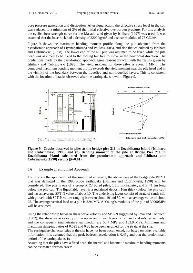
Comparisons have also been made with the field measurements made in the piles at the Pier 211in Uozakihama Island after the Hyogoken-Nambu earthquake which occurred on 17th January1995. Piles at bridge Pier 211 have a diameter of 1.5 m, and Figure 9 shows the crack distributionsobserved in piles after the earthquake. Ishihara and Cubrinovski (1998) have simulated this case,using their approach, and Liyanapathirana and Poulos (2005) also analysed it using theirpseudostatic approach. The water table was 2.0 m below the ground surface and the upper 20 mof this site consisted of Masado sand with an initial shear modulus of 57.8 MN/m2 and density of2000 kg/m3. Soil liquefaction was observed in the Masado sand layer below the water table only.Therefore only the top 20 m layer was analysed using the effective stress method incorporating
DFI Melbourne 2017. Designing piles for seismic events. H.G. Poulos
17
pore pressure generation and dissipation. After liquefaction, the effective stress level in the soilwas reduced to a minimum of 2% of the initial effective overburden pressure. For this analysisthe cyclic shear strength curve for the Masado sand given by Ishihara (1997) was used. It wasassumed that the base rock had a density of 2200 kg/m3 and a shear modulus of 75 GN/m2.
Figure 9 shows the maximum bending moment profile along the pile obtained from thepseudostatic approach of Liyanapathirana and Poulos (2005), and also that calculated by Ishiharaand Cubrinovski (1998). The lower end of the RC pile was assumed to be fixed while the pilehead was assumed to be fixed to the footing but free to move in the horizontal direction. Thepredictions made by the pseudostatic approach agree reasonably well with the results given byIshihara and Cubrinovski (1998). The yield moment for these piles is about 5 MNm. Thecomputed maximum bending moment profile exceeds the yield moment near the pile head and inthe vicinity of the boundary between the liquefied and non-liquefied layers. This is consistentwith the location of cracks observed after the earthquake shown in Figure 9.
Figure 9 Cracks observed in piles at the bridge pier 211 in Uozakihama Island (Ishiharaand Cubrinovski, 1998) and (b) Bending moment of the pile at Bridge Pier 211 inUozakihama Island calculated from the pseudostatic approach and Ishihara andCubrinovski (1998) results (β=0.01).
6.6 Example of Simplified Approach
To illustrate the application of the simplified approach, the above case of the bridge pile BP211that was damaged in the 1995 Kobe earthquake (Ishihara and Cubrinovski, 1998) will beconsidered. The pile is one of a group of 22 bored piles, 1.5m in diameter, and is 41.5m longbelow the pile cap. The liquefiable layer is a reclaimed deposit 16m thick (below the pile cap)and has an average SPT-N value of about 10. The underlying layers consist of strata of sandy silt,with gravel, with SPT-N values ranging between about 10 and 50, with an average value of about25. The average vertical load on a pile is 2.94 MN. A Young’s modulus of the pile of 30000MPawill be assumed.
Using the relationship between shear wave velocity and SPT-N suggested by Imai and Tonouchi(1982), the shear wave velocity of the upper and lower layers is 173 and 234 m/s respectively,and the consequent small-strain shear moduli are 53.7 MPa and 103.9 MPa. Minimum andmaximum damping ratios of 0.025 and 0.26 have been assumed for the strata at the site.The earthquake characteristics at the site have not been documented, but based on other availableinformation, it is assumed that the peak bedrock acceleration is 0.45g and that the predominantperiod of the earthquake is 1s.Assuming that the piles have a fixed head, the inertial and kinematic maximum bending momentscan be estimated for two cases:
F i g u r e 8 . C r a c k s o b s e r v e d i n t h e p i l e s a t b r i d g e p i e r 2 1 1 i nU o z a k i h a m a I s l a n d ( I s h i h a r a a n d C u b r i n o v s k i , 1 9 9 8 ) .
-46
-36
-26
-16
-6
-15 -10 -5 0 5 10 15
Bending moment (MNm)
Dep
th(m
)
Pseudostatic
Ishihara and Cubrinovski (1998)
DFI Melbourne 2017. Designing piles for seismic events. H.G. Poulos
18
• During the cyclic loading stage and prior to liquefaction;
• After liquefaction of the upper layer has developed.
(a) Cyclic Loading Phase
For the first case, the first step is to assess the amplification of ground motion, and based onthe above assumptions, the natural period of the site is about 0.79s. Using, as anapproximation, the classical expression for amplification of uniform harmonic motion, theratio of predominant period to natural period is about 1.27, and for a damping ratio of 0.025,the amplification factor is found to be 2.64. Thus, the peak ground surface acceleration isestimated to be 0.45*2.64 = 1.188g. Using the small-strain modulus values, the followingmaximum moments are computed:
Inertial: -7.65 MNm (using equation 24)Kinematic: 3.10 MNm (using the method of Nikolau et al, 2001, equations 5 to 9).
(b) Post-liquefaction phase
The small-strain modulus is used for the lower non-liquefiable layer, but a degraded modulusis used for the liquefied layer. To obtain this degraded modulus, given that liquefaction didindeed occur, a Liquefaction Potential Index, LPI, of 50 can be used. From equation 20, thereduction factor β is 0.01 (the limiting value assumed). The corresponding value of shearmodulus is 0.54 MPa. The site period now becomes 1.10s, while the damping ratio hasincreased to its assumed maximum value of 0.26. Accordingly, the amplification factor fromthe classical dynamic theory decreases from 2.64 (for no shear modulus degradation) to 1.64(for LPI=50), and the peak ground acceleration is then 0.45*1.64 = 0.738g.
From the expressions for inertial and kinematic bending moments (equations 24 and 5 to 9),the following values are obtained:
• Inertial moment (at pile head): -11.96 MNm
• Kinematic moment: 121.1 MNm.
However, a check needs to be made with the limiting kinematic bending moment that can occurwhen the liquefied layer flows past the pile. Adopting an undrained shear strength of 3 kPa forthe liquefied soil, the limiting bending moment is found, from equation 27, to be 12.3 MNm. It isclear that the assumption of elastic behaviour in the Nikolau et al method (giving a huge kinematicmoment of 121.1 MNm) is not valid in this case.
The values obtained from this simple analysis compare reasonable well those reported byLiyanapathirana and Poulos (2005) (approximately -9 MNm at the pile head and about 12 MNmat the base of the liquefied layer). Ishihara and Cubrinovski (1998) incorporated pile cracking intotheir analysis, and their computed maximum moments of about 7MNm reflect the occurrence ofpile cracking, which limited the moment that could be induced in the piles. Figure 9 shows detailsof two piles that were excavated and shows the cracks in the piles at or near these two locations.
Most importantly, the simplified analysis indicates that large moments would have been generatedat both the pile head and at the interface between the liquefied and non-liquefied layer.
DFI Melbourne 2017. Designing piles for seismic events. H.G. Poulos
19
6.7 Group Effects
Under inertial loading, it is now well-recognised that group effects are detrimental in that theytend to reduce the stiffness of piles within the group and decrease the overall group capacity.Methods of dealing with these effects are given by Poulos and Davis (1980) and Fleming et al(2009).
Under kinematic loading, group effects however tend to be beneficial, due to the “shielding”action of the piles. In particular, inner piles within a group tend to be subjected to smaller forcesand moments developed by ground movements than outer piles, and all piles in the group tend toexperience less effect than a single isolated pile. As a consequence, the consideration of a singleisolated pile will generally be conservative when considering kinematic effects.
Towhata (2008) has presented an approximate approach for estimating the reduction in lateralearth pressure on a pile due to soil movement or flow past a group of piles. This reduction can beexpressed in terms of two components:
1) A “shadow factor” which reduces the “downstream” pressure by a factor of 0.8 for eachsuccessive row of piles;
2) A spacing factor, αp, which can be expressed as follows:
(i) For a non-liquefied layer:
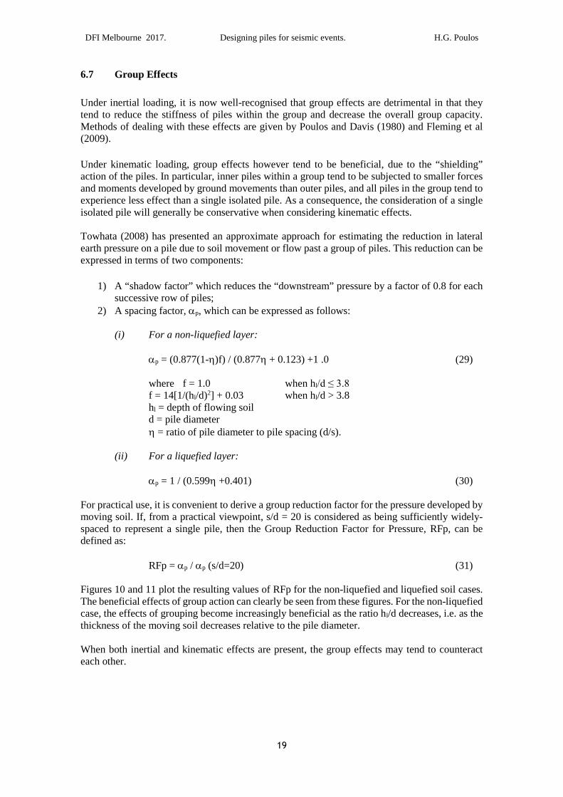
αp = (0.877(1-η)f) / (0.877η + 0.123) +1 .0 (29)
where f = 1.0 when hl/d ≤ 3.8 f = 14[1/(hl/d)2] + 0.03 when hl/d > 3.8hl = depth of flowing soild = pile diameterη = ratio of pile diameter to pile spacing (d/s).
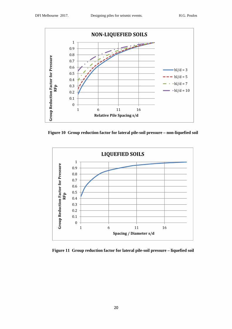
(ii) For a liquefied layer:
αp = 1 / (0.599η +0.401) (30)
For practical use, it is convenient to derive a group reduction factor for the pressure developed bymoving soil. If, from a practical viewpoint, s/d = 20 is considered as being sufficiently widely-spaced to represent a single pile, then the Group Reduction Factor for Pressure, RFp, can bedefined as:
RFp = αp / αp (s/d=20) (31)
Figures 10 and 11 plot the resulting values of RFp for the non-liquefied and liquefied soil cases.The beneficial effects of group action can clearly be seen from these figures. For the non-liquefiedcase, the effects of grouping become increasingly beneficial as the ratio hl/d decreases, i.e. as thethickness of the moving soil decreases relative to the pile diameter.
When both inertial and kinematic effects are present, the group effects may tend to counteracteach other.
DFI Melbourne 2017. Designing piles for seismic events. H.G. Poulos
20
Figure 10 Group reduction factor for lateral pile-soil pressure – non-liquefied soil
Figure 11 Group reduction factor for lateral pile-soil pressure – liquefied soil
0
0.1
0.2
0.3
0.4
0.5
0.6
0.7
0.8
0.9
1
1 6 11 16
Gro
up
Re
du
ctio
nF
act
or
for
Pre
ssu
reR
Fp
Relative Pile Spacing s/d
NON-LIQUEFIED SOILS
hl/d = 3
hl/d = 5
hl/d = 7
hl/d = 10
0
0.1
0.2
0.3
0.4
0.5
0.6
0.7
0.8
0.9
1
1 6 11 16Gro
up
Re
du
ctio
nF
act
or
for
Pre
ssu
reR
Fp
Spacing / Diameter s/d
LIQUEFIED SOILS
DFI Melbourne 2017. Designing piles for seismic events. H.G. Poulos
21
7 FOUNDATION STIFFNESS AND DAMPING
Piles will experience vertical and horizontal movements during an earthquake due to the inertialloadings imposed by the supported structure. These movements will generally be dynamic innature and therefore it is necessary to consider the pile head stiffnesses under dynamic loading,and the damping that will be generated by the dissipation of energy away from the piles into thesurrounding soil (the radiation damping). Knowledge of foundation stiffness and damping is alsorequired to assess the effects of structure-foundation interaction on the natural period and dampingof a structure.
Theoretical solutions for the axial and lateral stiffnesses of a single pile have been provided byNovak (1987) among others. Convenient approximate solutions have been given by Gazetas(1991) for various simplified soil profiles.
In contrast to static loading, where the interaction factors between piles decrease with increasingdistance between the interacting piles, the dynamic interaction factors can either increase ordecrease, depending on the frequency of the loading and the spacing between the piles. It ispossible that the interaction factors can be negative under some circumstances, so that groupeffects may possible lead to an increase in stiffness of the piles within a group, as compared withthe case of static loading, where group effects generally reduce the stiffness of piles in the group.For practical design, it may often be more convenient to simplify the group as an equivalent pier,and then to use the corresponding solutions for stiffness and damping as given by Gazetas (1991).
8 MITIGATION OF LIQUEFACTION EFFECTS
8.1 Categories of Mitigation Measures
Conventional remedial measures to mitigate the effects of liquefaction can be divided into threebroad categories (JGS, 1998):
• Treatment of the liquefiable soil to strengthen it;
• Treatment of the soil to accelerate the dissipation of seismically-induced excess pore
pressures;
• Measures to reduce liquefaction-induced damage to the structure or facility.
8.2 Conventional Measures to Strengthen the Liquefiable Soil
An extensive discussion of measures that can be used to strengthen liquefaction-susceptible soilsis given in JGS (1998). Some of the more common measures are as follows:• Soil densification, by a variety of means, e.g. vibroflotation, blasting;
• Insertion of stiffer columns;
• Provision of drainage via stone columns.
A major limitation of all of these methods is that they cannot be used to remediate sites on whichstructures or facilities already exist. A number of the methods for soil densification may also notbe feasible if the site is within a commercial or residential area, because of the noise and vibrationsinvolved.Methods involving the insertion of stiffer columns can be effective and generally involve lessnoise and vibration than conventional methods of densification.
DFI Melbourne 2017. Designing piles for seismic events. H.G. Poulos
22
8.3 Conventional Measures to Accelerate Excess Pore Pressure Dissipation
The use of stone columns or gravel drains to accelerate pore pressure drainage was developed bySeed and Booker (1977) and has been used successfully in a number of cases. In the design ofstone columns for liquefaction mitigation, it is common to specify a limiting maximum porepressure ratio (excess pore pressure divided by vertical effective stress), and this is often taken as50%. The required length of the columns will depend on the depth of the liquefiable layer, whilethe required spacing of the columns will depend on the following factors:
1. The specified maximum pore pressure ratio;
2. The permeability and compressibility of the liquefiable layer;
3. The earthquake duration;
4. The equivalent number of cycles of loading from the earthquake;
5. The number of cycles to cause liquefaction;
6. The column diameter;
7. The finite permeability of the column and the effects of well resistance.
8.4 Mitigation Measures for Pile Foundations
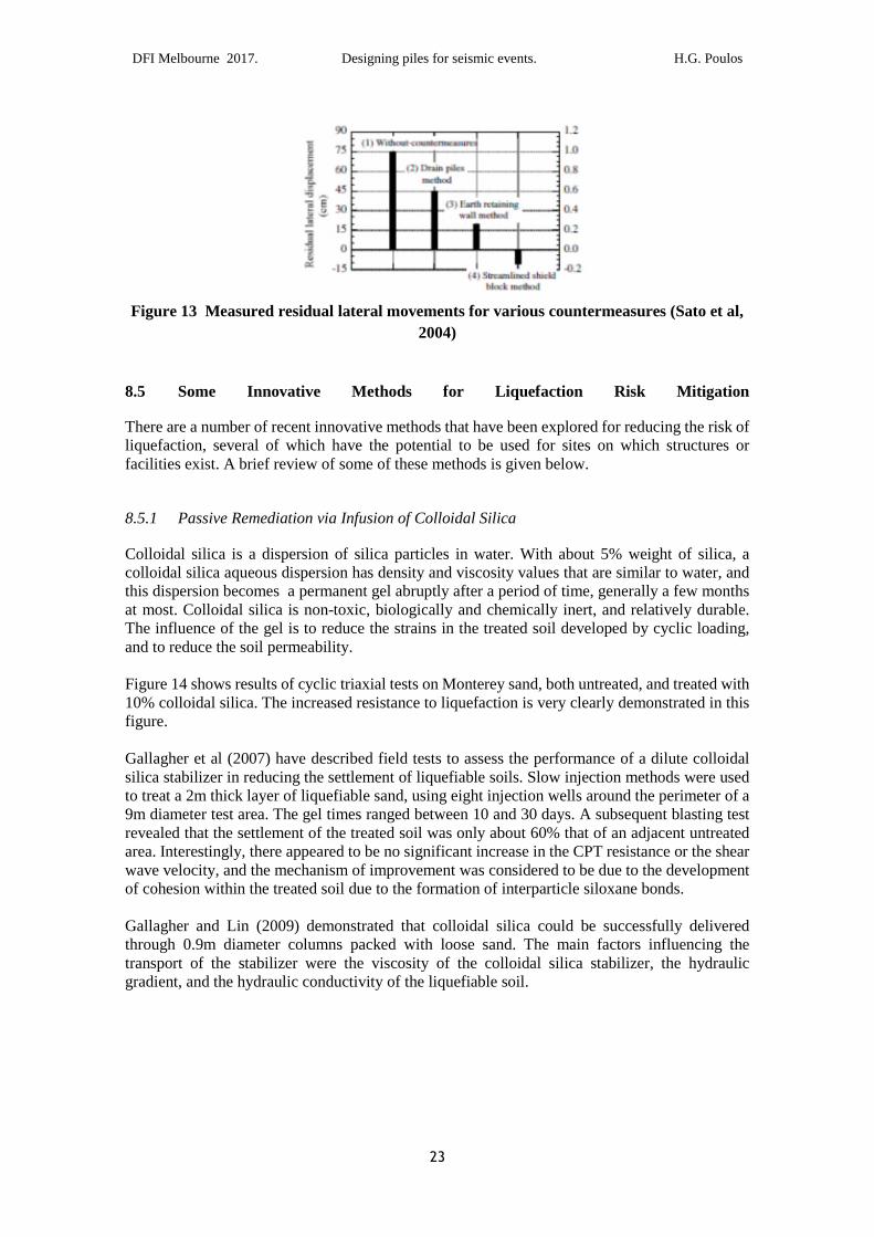
Sato et al (2004) have suggested various countermeasures for pile foundations subjected to lateral
flow of liquefiable soils. Three of these measures are illustrated in Figure 12.
The “drain piles” method aims to prevent the liquefaction of the lower layers while reducing the
stiffness of the stiffer crust above the liquefiable layers. The drain piles should extend only about
half-way into the upper crust, and the permeability of the drain piles should be greater than that
of the liquefiable layers so that the excess pore pressures that are generated are transmitted to the
upper layer. In the “earth retaining wall” method, an earth retaining wall is constructed in front
of the pile foundation, to block the lateral flow. The “streamlined shield block” method involves
the casting of an angled face on the upstream side of the pile cap. This angled face is meant to
disperse the flowing soil and reduce its effect on the foundation.
Centrifuge tests were carried out by Sato et al (2004) to examine the effectiveness of the above
countermeasures. Figure 13 summarises the test results and indicates that the “streamlined shield
block” method is very effective in reducing the residual lateral displacement, and also the bending
strain in the piles. It has the advantage of not requiring any ground improvement.
Figure 12 Countermeasures for lateral ground flow (Sato et al, 2004)
DFI Melbourne 2017. Designing piles for seismic events. H.G. Poulos
23
Figure 13 Measured residual lateral movements for various countermeasures (Sato et al,
2004)
8.5 Some Innovative Methods for Liquefaction Risk Mitigation
There are a number of recent innovative methods that have been explored for reducing the risk ofliquefaction, several of which have the potential to be used for sites on which structures orfacilities exist. A brief review of some of these methods is given below.
8.5.1 Passive Remediation via Infusion of Colloidal Silica
Colloidal silica is a dispersion of silica particles in water. With about 5% weight of silica, acolloidal silica aqueous dispersion has density and viscosity values that are similar to water, andthis dispersion becomes a permanent gel abruptly after a period of time, generally a few monthsat most. Colloidal silica is non-toxic, biologically and chemically inert, and relatively durable.The influence of the gel is to reduce the strains in the treated soil developed by cyclic loading,and to reduce the soil permeability.
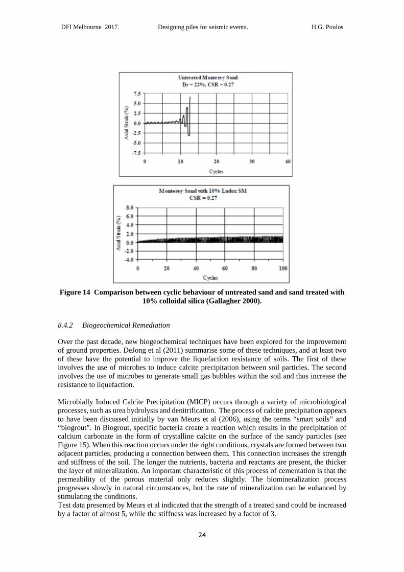
Figure 14 shows results of cyclic triaxial tests on Monterey sand, both untreated, and treated with10% colloidal silica. The increased resistance to liquefaction is very clearly demonstrated in thisfigure.
Gallagher et al (2007) have described field tests to assess the performance of a dilute colloidalsilica stabilizer in reducing the settlement of liquefiable soils. Slow injection methods were usedto treat a 2m thick layer of liquefiable sand, using eight injection wells around the perimeter of a9m diameter test area. The gel times ranged between 10 and 30 days. A subsequent blasting testrevealed that the settlement of the treated soil was only about 60% that of an adjacent untreatedarea. Interestingly, there appeared to be no significant increase in the CPT resistance or the shearwave velocity, and the mechanism of improvement was considered to be due to the developmentof cohesion within the treated soil due to the formation of interparticle siloxane bonds.
Gallagher and Lin (2009) demonstrated that colloidal silica could be successfully deliveredthrough 0.9m diameter columns packed with loose sand. The main factors influencing thetransport of the stabilizer were the viscosity of the colloidal silica stabilizer, the hydraulicgradient, and the hydraulic conductivity of the liquefiable soil.
DFI Melbourne 2017. Designing piles for seismic events. H.G. Poulos
24
Figure 14 Comparison between cyclic behaviour of untreated sand and sand treated with10% colloidal silica (Gallagher 2000).
8.4.2 Biogeochemical Remediation
Over the past decade, new biogeochemical techniques have been explored for the improvementof ground properties. DeJong et al (2011) summarise some of these techniques, and at least twoof these have the potential to improve the liquefaction resistance of soils. The first of theseinvolves the use of microbes to induce calcite precipitation between soil particles. The secondinvolves the use of microbes to generate small gas bubbles within the soil and thus increase theresistance to liquefaction.
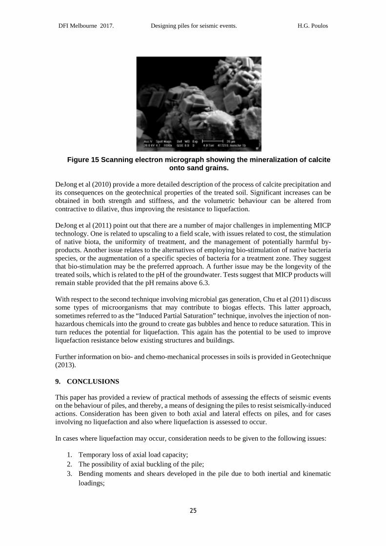
Microbially Induced Calcite Precipitation (MICP) occurs through a variety of microbiologicalprocesses, such as urea hydrolysis and denitrification. The process of calcite precipitation appearsto have been discussed initially by van Meurs et al (2006), using the terms “smart soils” and“biogrout”. In Biogrout, specific bacteria create a reaction which results in the precipitation ofcalcium carbonate in the form of crystalline calcite on the surface of the sandy particles (seeFigure 15). When this reaction occurs under the right conditions, crystals are formed between twoadjacent particles, producing a connection between them. This connection increases the strengthand stiffness of the soil. The longer the nutrients, bacteria and reactants are present, the thickerthe layer of mineralization. An important characteristic of this process of cementation is that thepermeability of the porous material only reduces slightly. The biomineralization processprogresses slowly in natural circumstances, but the rate of mineralization can be enhanced bystimulating the conditions.Test data presented by Meurs et al indicated that the strength of a treated sand could be increasedby a factor of almost 5, while the stiffness was increased by a factor of 3.
DFI Melbourne 2017. Designing piles for seismic events. H.G. Poulos
25
Figure 15 Scanning electron micrograph showing the mineralization of calciteonto sand grains.
DeJong et al (2010) provide a more detailed description of the process of calcite precipitation andits consequences on the geotechnical properties of the treated soil. Significant increases can beobtained in both strength and stiffness, and the volumetric behaviour can be altered fromcontractive to dilative, thus improving the resistance to liquefaction.
DeJong et al (2011) point out that there are a number of major challenges in implementing MICPtechnology. One is related to upscaling to a field scale, with issues related to cost, the stimulationof native biota, the uniformity of treatment, and the management of potentially harmful by-products. Another issue relates to the alternatives of employing bio-stimulation of native bacteriaspecies, or the augmentation of a specific species of bacteria for a treatment zone. They suggestthat bio-stimulation may be the preferred approach. A further issue may be the longevity of thetreated soils, which is related to the pH of the groundwater. Tests suggest that MICP products willremain stable provided that the pH remains above 6.3.
With respect to the second technique involving microbial gas generation, Chu et al (2011) discusssome types of microorganisms that may contribute to biogas effects. This latter approach,sometimes referred to as the “Induced Partial Saturation” technique, involves the injection of non-hazardous chemicals into the ground to create gas bubbles and hence to reduce saturation. This inturn reduces the potential for liquefaction. This again has the potential to be used to improveliquefaction resistance below existing structures and buildings.
Further information on bio- and chemo-mechanical processes in soils is provided in Geotechnique(2013).
9. CONCLUSIONS
This paper has provided a review of practical methods of assessing the effects of seismic eventson the behaviour of piles, and thereby, a means of designing the piles to resist seismically-inducedactions. Consideration has been given to both axial and lateral effects on piles, and for casesinvolving no liquefaction and also where liquefaction is assessed to occur.
In cases where liquefaction may occur, consideration needs to be given to the following issues:
1. Temporary loss of axial load capacity;
2. The possibility of axial buckling of the pile;
3. Bending moments and shears developed in the pile due to both inertial and kinematic
loadings;
DFI Melbourne 2017. Designing piles for seismic events. H.G. Poulos
26
4. The possible beneficial effects of group action in reducing kinematically-induced bending
moments.
It has been demonstrated that bending moments are likely to be a maximum at or near soil layerinterfaces where there is a significant difference in the stiffness of the layers. An important caseis at the junction between liquefied and non-liquefied layers. A further consequence of thisbehaviour is that large bending moments may occur well below the pile head, where it has beencustomary in the past to reduce or eliminate reinforcement in concrete piles because the momentsdue to inertial loads have become small. Unfortunately, in cases of earthquake loading, thekinematically-induced moments may be substantial at depth if the soil is layered and the stiffnessof adjacent layers differs markedly.
There are a number of methods available for mitigating the effects of liquefaction. While someof the more traditional methods may be suitable for green-field sites, they may not be feasible forexisting sites. In such cases, some of the more recent innovative methods involving bio-geo-chemical processes hold considerable promise, provided that they can be demonstrated to beeconomically feasible at field scale.
REFERENCES
Abdoun, T., Dobry, R. and O’Rouke, T.D. (1997). “Centrifuge and Numerical Modelling of Soil-
Pile Interaction During Earthquake Induced Soil Liquefaction and Lateral Spreading.”
Observation and Modelling in Numerical Analysis and Model Tests in Dynamic Soil-
Structure Interaction Problems – Proceedings of Sessions held in conjunction with Geo-
Logan ’97, Logan Utah, 76-90.
Bhattacharya, S. and Bolton. M. (2004). Errors in design leading to pile failures during seismic
liquefaction. Proc. 5th Int. Conf. Case Histories in Geot. Eng., New York, Paper No. 12A-12.
Chu, J., Ivanov, V., He, J., Naemi, M., Li, B. and Stabnikov, V. (2011). Development of microbial
geotechnology in Singapore. Proc. Geo-Frontiers 2011 Conf., ASCE Conf. Proc.
Doi:10.1061/41165:397-416.
Cubrinovski, M. (2013). Liquefaction-Induced Damage in the 2010-2011 Christchurch (New
Zealand) Earthquakes. Paper EQ-1, 7th Int. Conf. Case Histories in Geot. Eng., Chicago, CD
Volume, ISBN #1-887009-17-5.
Cubrinovski, M. and Ishihara, K. (2004) Simplified Method for Analysis of Piles Undergoing
Lateral Spreading in Liquefied Soils. Soils and Foundations 44(5): 119-133.
Cubrinovski, M., Ishihara, K. and Poulos, H.G. (2009). Pseudo-static Analysis of Piles Subjected
to Lateral Spreading. Bull. New Zealand Soc. Earthqu. Eng., 42(1): 28-38.
Madhabhushi, S.P.G. and May, R. (2009). Pile foundations. Chapter 9 of Seismic Design of
Buildings to Eurocode 8, A.Y. Elghazouli (Ed), Spon Press, London.
Mina, S. and Ikeda, T. (2006). Shear modulus and strain of liquefied ground and their app;lication
to evaluation of the response of foundation structures. Struct. Eng./Earthquake Eng, 23(1):
167s-179s.
Nikolaou S., Mylonakis G., Gazetas G. and Tazoh T. (2001) Kinematic Pile Bending duringEarthquakes: Analysis and Field Measurements. Geotechnique, 51, 425−440.
Novak, M. (1987). State of the art in analysis and design of machine foundations”. Soil Structure
Interaction, Elsevier/CML Publ, New York, 171-192.
DFI Melbourne 2017. Designing piles for seismic events. H.G. Poulos
28
Poulos, H.G. (1989). Pile Behaviour – Theory and Application. 29th Rankine Lecture,
Poulos, H.G. and Davis, E.H. (1980). Pile foundation analysis and design. John Wiley, New
York.
Randolph, M.F. (1981). The response of flexible piles to lateral loading. Geotechnique, 31(2):
247-259.
Sato, K., Higuchi, S. and Matsuda, T. (2004). A study of the effect of countermeasures for pile
foundation under lateral flow caused by ground liquefaction. Proc. 13th World Conf.
Earthquake Eng., Vancouver, Paper No. 452.
Seed, H.B. and Booker, J.R. (1977). Stabilization of potentially liquefiable sand deposits. Jnl.
Geot. Eng., ASCE, 103(GT7): 757-768.
Sica S., Mylonakis G., Simonelli A.L. (2011) Transient kinematic pile bending in two layer soils.Soil Dynamics and Earthquake Engineering , Vol. 31, pp. 891-905.
Tabesh, A. and Poulos, H.G. (2001). Pseudostatic approach for seismic analysis of single piles.
Jnl. Geot. & Geoenv. Eng., ASCE, 127(9): 757-765.
Tabesh, A. and Poulos, H.G. (2007). Design Charts for Seismic Analysis of Single Piles in Clay.
Proc. ICE, Geotechnical Engineering, 160(GE2): 85-96.
Tokimatsu, K., Suzuki, H. & Sato, M. (2005). Effects of inertial and kinematic interaction on
seismic behaviour of pile with embedded foundation. Soil Dynamics and Earthquake
Engineering, 25(753-762).
Towhata, I. (2008). Geotechnical Earthquake Engineering. Springer, Berlin.
Wilson, D.W., Boulanger, R.W. and Kutter, B.L. (1999). Lateral Resistance of Piles in Liquefying
Sand. Geotechnical Special Publication No. 88, pp. 165-179.
van Meurs, G., van der Zon, W., Lambert, J., van Ree, D., Whiffin, V. and Molendijk, W. (2006).
The challenge to adapt soil properties. Proc. 5 ICEG: Environ. Geotechnics: Opportunities,
Challenges and Responsibilities for Env. Geotechnics, 2: 1192-1199.
Valsamis A., Bouckovalas G., Chaloulos Y. (2012. "Parametric analysis of single pile responsein laterally spreading ground". Soil Dynamics and Earthquake Engineering, Vol. 34, pp. 99-100.