DESIGNING UNDER HIGH T CONDITION The effect of service environment on material performance at elevated T can be divided into 3 main categories : Microstructural effects, such as grain growth & overaging Chemical effects, such as oxidation Mechanical effects, such as creep & stress rupture Oxidation – in metals start rapidly & form oxide film or scale on the surface. Rate of further oxidation depends on soundness of the film. E.g sodium & potassium – porous, Al & Cr – film is dense & provides protection against further oxidation. To improve – alloying, protective coating. Most plastics & rubbers – oxidize & process is called ageing. It reduced elasticity & increases hardness because O 2 diffuses into structure & provides additional cross-linking.
Transcript
DESIGNING UNDER HIGH T CONDITIONThe effect of service environment on material performance at elevated T can be divided into 3 main categories :
Microstructural effects, such as grain growth & overaging Chemical effects, such as oxidation Mechanical effects, such as creep & stress rupture
Oxidation – in metals start rapidly & form oxide film or scale on the surface. Rate of further oxidation depends on soundness of the film. E.g sodium & potassium – porous, Al & Cr – film is dense & provides protection against further oxidation.
To improve – alloying, protective coating.
Most plastics & rubbers – oxidize & process is called ageing. It reduced elasticity & increases hardness because O2 diffuses into structure & provides additional cross-linking.
DESIGNING UNDER HIGH T CONDITIONOxidation and creep can directly lead to failure of a part in service.The microstructural changes can lead to weakening of the material, and therefore can indirectly lead to failure.Many of the strengthening mechanisms that are effective at room temperature become ineffective at elevated temperature.Generally non-equilibrium structures change during long-term high T service and this lead to lower the creep strength.Thus, material which depend on fine grain for strengthening will lose this advantages by grain growth.
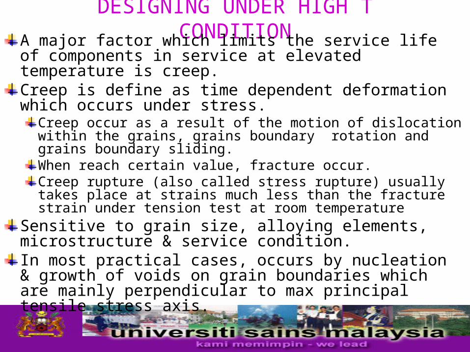
DESIGNING UNDER HIGH T CONDITIONA major factor which limits the service life of components in service at elevated temperature is creep.Creep is define as time dependent deformation which occurs under stress.
Creep occur as a result of the motion of dislocation within the grains, grains boundary rotation and grains boundary sliding.When reach certain value, fracture occur.Creep rupture (also called stress rupture) usually takes place at strains much less than the fracture strain under tension test at room temperature
Sensitive to grain size, alloying elements, microstructure & service condition. In most practical cases, occurs by nucleation & growth of voids on grain boundaries which are mainly perpendicular to max principal tensile stress axis.
DESIGNING UNDER HIGH T CONDITIONMost cases, strain can be divided into 3 stages –
1. Primary (initial) ; initial instantaneous deformation, creep takes place at decreasing strain rate.
2. Secondary ; steady-state, rate is constant under constant stress conditions.
3. Tertiary ; creep starts and creep rate increases rapidly with increasing strain and fracture finally occurs.
Tertiary creep can be caused by: – Reduction of cross-sectional area of component due to cracking or necking.
Oxidation and other environmental effects, which reduce the cross sectional area.
Microstructural changes that weaken material.
Creep curve under tensile loading
Combination of creep & fatigue In many high-temperature applications in practice, the applied load are cyclic and could lead to combined creep-fatigue failure.Under theses conditions, the life of a component is determined by the initiation and growth of a creep or fatigue crack.At high load frequencies and/or relatively lower temperature, crack growth is independent of the frequency or temperature.
This because the material just ahead of the crack does not suffer any time-dependent processes, such as oxidation or creep relaxation
DESIGNING UNDER HIGH T CONDITION
Under these condition, the mechanism of crack growth is essentially the same as room temperature fatigue.
At low frequencies and/or relatively high temperature, crack growth is affected by time-dependent processes.
A mixture of the two extreme cases of behavior is expected at intermediate temperature and load frequencies.
DESIGNING UNDER HIGH T CONDITION
Thermal fatigue
Another form of elevated-temperature failures is thermal fatigue.
Stresses & strains induced in component due to thermal gradient can cause failure if repeated a sufficient number of time.
Faster change in temperature, lower thermal conductivity of the material, higher elastic constant, higher thermal expansion coefficient, lower ductility and thicker component section often accounts for shorter service life.
Ceramic are particularly prone to thermal fatigue.
DESIGNING UNDER HIGH T CONDITION
In high temperature applications, the environment plays an important role in determining the performance of component
Selecting the material that will resist the environment, controlling the environment, or protecting the surface is essential for prolong service
DESIGNING UNDER HIGH T CONDITION
DESIGNING UNDER HIGH T CONDITION
It become clear that the service temperature has a considerable influence on the strength of material and, consequently, on the working stress used in design.
Depending on the temperature range, the design can based on :
1. Short-time properties of the material, as described by the yield strength and UTS , for moderate T
2. Both short-time and creep properties for intermediate T range.
3. Creep properties of the materials for high T
DESIGNING UNDER HIGH T CONDITIONIn addition of creep, other factors which must be taken into account when designing for elevated T include :
Metallurgical & microstructure change which occur in the material due to long-time exposure to elevated T
Influence of method of fabrication, especially welding, on creep behavior.
Oxidation & hot corrosion
Design guidelineFor design purposes, properties usually presented on plots which yield reasonable straight lines. Common methods of presentation is log-log plots of stress vs steady state creep rate.Change in microstructure of the material, will change in creep properties and consequently a change in the slope of the line.Generally, designing under high temperature condition is carried according to well-established codes.
E.g ASME Boiler & Pressure Vessel Code, BS 806:1975 (piping for land boilers).
DESIGNING UNDER HIGH T CONDITION
The common feature of such codes is that calculation and stress analysis are kept to a minimum.
The design of local area, such as branch connections and supports, is provided by simple formulas and by reference to chart.
Generally, service temperature and pressure are lower than design value and material properties are usually higher than those specified.
DESIGNING UNDER HIGH T CONDITION
Variation of stress with T (steady state)
DESIGNING UNDER HIGH T CONDITIONLarson-Miller parameterCreep data are incomplete and have to be supplement or extended by interpolation or extrapolation.This is particularly true for long time creep and stress-rapture data where the 100,000 hr (11.4 years) creep resistance of newly developed materials is required.As an aid in extrapolation creep data, several time-temperature parameter have been developed for trading off for time. The basic idea – permit prediction of long time creep behavior from results of shorter time tests at higher & at the same stress.
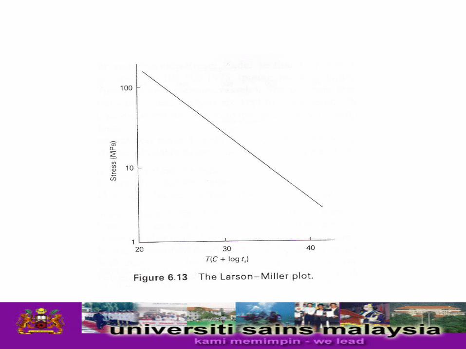
DESIGNING UNDER HIGH T CONDITIONWidely used parameter for correlating creep fracture data is the Larson-Miller, LMP ;
LMP = T (C + log tr)
T – test T in Kelvin (°C + 273)
tr – time to fracture in hrs
C – Larson-Miller constant which generally falls between
17 and 23, but often taken to be 20.
The LMP can also be expressed in terms of time to give specified strain, ts.
LMP = T (C + log ts)
DESIGNING UNDER HIGH T CONDITIONCreep resistance of metal
The operating temperature approaches melting temperature is ineffective, when
T > 0.3 – 0.4Tm for metal
T > 0.4 – 0.5Tm for ceramicBecause atomic mobility becomes sufficient to cause softening of cold-worked structure and coarsening of unstable precipitates.At these high temperature, the differences in creep resistance from one material to another depend on the stability of the structure and on the hardening mechanism.
DESIGNING UNDER HIGH T CONDITIONMost important method of improving creep strength is to incorporate a fine dispersion of stable second phase particle within grain.
These particles can be introduced by dispersion, as in the case of thoria particle in nickel, or by precipitation, as in the case of precipitation-hardened nickel alloys.
Precipitates at the grain boundaries are important in controlling creep rupture ductility, as they control grain boundary sliding, which causes premature failure.
DESIGNING UNDER HIGH T CONDITION
Performance of plastics at high TMechanical strength of plastics at high T usually compared on the basics deflection T under load ( DTUL )
DTUL- Define as T at which specimen deflect 0.25 mm under load of 455 or 1820 kPa, when heated at the rate of 2oC/minute.
Generally, thermoset have high T resistance than thermoplastics.
However, thermoplastics DTUL can be improve by adding glass and carbon fibers, as well as mineral and ceramic reinforcement.
Eg. 30 % glass fiber added to nylon 6/6 give DTUL at 1820 kPa increase from about 71 – 249oC
DESIGNING UNDER HIGH T CONDITION
While several plastic an withstand short excursions to high temperatures, up-to 500oC, continuous exposure can result in a dramatic drop in mechanical properties and extreme thermal degradation.
Because operating temperature is the single most important factor that affects the selection of materials for elevated-temperature service, it is normal practice to classify temperature-resistant material according to the temperature range in which they are expected to be used.
Selection of Material Room T to 150°C –
Most engineering metals & alloys except lead. Several unreinforced thermoplastic are suitable for continuous service at T > 100°C.
Several fiber reinforced plastics.E.g : nylon 6/6-glass fiber, can also serve in this temperature range
150 - 400°C - Plain C or Mn-C steel, or if very long-service low-alloy steel. Up to 250°C – high-grade cast irons, Al alloys. High T plastics can withstand T 200 – 300oC for short periods.
E.g : polyphenylenesulphides, polyethersulphoneFor long periods – polyparaphenylene benzobisthiazole ( can withstand T up to 370oC
400 - 600°C - Low-alloy steel & Ti alloys are main materials used in this range.
Low-alloy steel is inexpensive & used if no restriction on weight.
Mains alloying element are usually added – Mo, Cr, V
Eg :0.2Cp-1Cr-1Mo-0.25V – used for intermediate and high pressure steam turbine motors
Ti alloy -phase structure exhibit better creep resistance than -phase structure