Page 1
PROJECT REPORT
on
DESIGN and TEST an ASTERISK VoIP SYSTEM for NUR NETWORK
By
Desire AHEZA
(Reg No UG10102389)
Under the guidance of
Dr Felix K. AKORLI
Submitted to the Department of Electrical and Electronics
in the FACULTY OF APPLIED SCIENCES
In partial fulfillment of the requirements
for the award of the degree
of
BACHELOR OF ENGINEERING
IN
ELECTRONICS AND COMMUNICATION SYSTEMS ENGINEERING
National University of Rwanda
Faculty of Applied Sciences
Department of Electrical and Electronics
October 2011
Page 2
i
BONAFIDE CERTIFICATE
Certified that this project report titled “DESIGN and TEST an ASTERISK VoIP SYSTEM
for NUR NETWORK” is the bonafide work of Mr. AHEZA Desire who carried out the
research under my supervision. Certified further, that to the best of my knowledge the work
reported herein does not form part of any other project report or dissertation on the basis of
which a degree or award was conferred on an earlier occasion on this or any other candidate.
Signature of the Guide Signature of the H.O.D
Name of the Guide (Certificate to be countersigned by the HOD.)
Where external guide is also there, the following format may be followed.
Signature of Internal Guide:
Name:
Signature of External Guide:
Name:
Page 3
ii
DECLARATION
I declare that, the project entitled, “DESIGN and TEST an ASTERISK VoIP SYSTEM for
NUR NETWORK” is original work and has never been submitted to any University or other
Institutions of Higher Learning. It is my own research whereby other scholar’s writings were
cited and references provided. I thus declare this work is mine and was complete successfully
under the supervisor Dr Felix K. AKORLI.
Student’s signature
Name:
Page 4
iii
Dedication
To my Almighty God
To my parents
To my relatives, colleagues and friends
This project is dedicated
Desire AHEZA
Page 5
iv
Acknowledgement
I am thankful to the Almighty God for the given gift of life and guidance, especially during the
development of this project.
My sincere thanks go foremost to Dr Felix K. AKORLI for accepting to supervise this project;
without his guidance, support and advice, I would not have succeeded to complete this work.
I wish to acknowledge all lectures in the Faculty of Applied Sciences, especially those of the
Electrical and Electronics department, the National University of Rwanda and the Rwandan
Government for the opportunities they have given us to obtain these skills.
My thanks are also expressed to the NUR Masters program in ICT for providing us the
necessary equipments like computers, switches that helped me to complete this project.
Appreciation is also extended to the NUR ICT center team especially MUNEZERO Moussa for
his support, and to DPD System Administrator Mr. Ben RUHINDA for his support, advice and
help to get needed information to the achievement of the goals of this project.
Special gratitude is concentrated on my beloved parents for their parental love and daily support
in my education.
The last but of course not least, I am grateful to my classmates especially ABIJURU Delphine
for IVR voice prompts she made for me.
GOD Bless you all
Desire AHEZA
Page 6
v
Table of content
BONAFIDE CERTIFICATE ...................................................................................................... i
DECLARATION ....................................................................................................................... ii
Dedication ................................................................................................................................. iii
Acknowledgement .................................................................................................................... iv
List of abbreviations and acronyms ......................................................................................... viii
List of Figures .......................................................................................................................... xii
List of Tables .......................................................................................................................... xiii
Abstract ...................................................................................................................................xiv
Chapter1. Introduction ................................................................................................................1
1.1 Background .......................................................................................................................1
1.2 Problem Statement .............................................................................................................2
1.3 Research hypothesis ...........................................................................................................2
1.4 Objectives ..........................................................................................................................3
1.5 Scope of the project ...........................................................................................................3
1.6 Interest of the project .........................................................................................................3
1.7 Organization of the project .................................................................................................4
Chapter 2.VoIP Technology and Protocols ..................................................................................5
2.1 Telephony ..........................................................................................................................5
2.2 VoIP Standards and Protocols ............................................................................................7
2.2.1 Standards and Protocols...............................................................................................8
2.2.2 Codecs ...................................................................................................................... 13
2.2.3 Asterisk Private Branch eXchange ............................................................................. 14
2.3 VoIP Servers and End Users ............................................................................................ 16
2.3.1 3CX Phone System for Windows .............................................................................. 16
2.3.2 Pure Asterisk ............................................................................................................. 16
2.3.3 Customized Linux Distributions ................................................................................ 17
2.3.4 Client Sides ............................................................................................................... 17
Page 7
vi
Chapter3. Method for data collection, Tools and QoS metrics ................................................... 18
3.1 Data collection ................................................................................................................. 18
3.1.1 Gathered Documents ................................................................................................. 18
3.1.2 Investigation Techniques ........................................................................................... 18
3.1.3 Interviews approach .................................................................................................. 18
3.2 Information of the TrixBox CE open source IP PBX system ............................................ 19
3.3 Tools ............................................................................................................................... 19
3.3.1 Hardware................................................................................................................... 19
3.3.2 Software .................................................................................................................... 20
3.4 Quality of Services (QoS) ................................................................................................ 20
3.4.1 QoS requirements for Voice application .................................................................... 21
3.4.2 QoS Requirements of Video application .................................................................... 21
3.5 Estimation of QoS of VoIP .............................................................................................. 22
3.5.1 E-model and Gap model description .......................................................................... 22
3.5.2 Gap model ................................................................................................................. 24
Chapter4. Design and Test of NUR VoIP System ...................................................................... 25
4.1 Planning NUR dialplan prototype .................................................................................... 25
4.1.1 Units of NUR ............................................................................................................ 25
4.1.2 Dial plan.................................................................................................................... 26
4.1.3 VoIP features to offer ................................................................................................ 27
4.2 Setup of TrixBox Server .................................................................................................. 30
4.2.1 Hardware requirements.............................................................................................. 30
4.2.2 Installation of TrixBox System .................................................................................. 30
4.3 Configuring the VoIP Server ............................................................................................ 31
4.3.1 Configuring Extensions and Voicemails .................................................................... 31
4.3.2 Configure ring group application ............................................................................... 33
4.3.3 Configure Follow me application............................................................................... 34
4.3.4 Configure queuing ..................................................................................................... 35
4.4 Testing of NUR VoIP System .......................................................................................... 35
Page 8
vii
4.5 Verification of VoIP metrics ............................................................................................ 37
4.6 Maintenance .................................................................................................................... 39
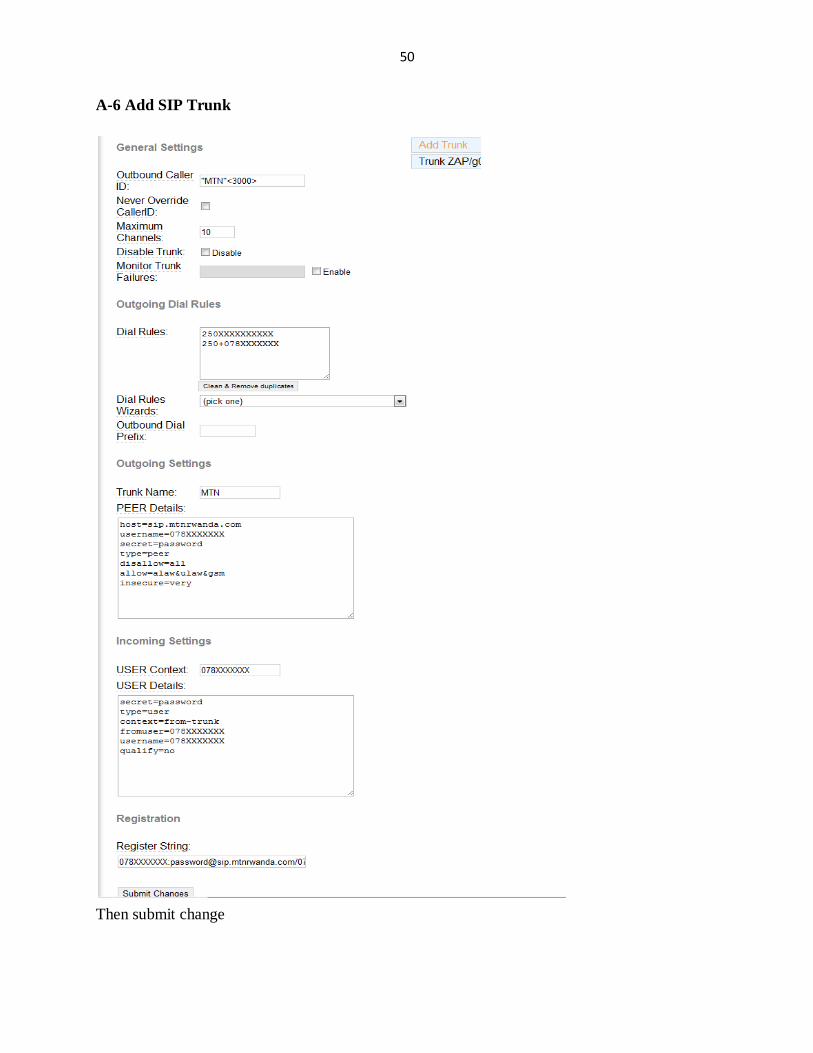
4.6.1 Create a SIP Trunk ........................................................................................................ 40
4.6.2 Security Issues........................................................................................................... 41
Chapter5. Conclusion and Recommendations ............................................................................ 42
5.1 Conclusion ....................................................................................................................... 42
5.2 Recommendation ............................................................................................................. 42
References ................................................................................................................................ 43
Appendix .................................................................................................................................. 45
Page 9
viii
List of abbreviations and acronyms
ACK: Acknowledgement
AGI: Asterisk Gateway Interface
API: Application Programming Interface
ARPANET: Advanced Research Projects Agency Network
ATA: Analog Telephone Adapter
BRI: Basic Rate Interface
CCITT: Consultative Committee for International Telephony and Telegraphy
CD: Compact Disk
CDR: Customer Details Records
CD-ROM: Compact Disc, Read-Only-Memory
Codec: coder/decoder
CPU: Central Processing Unit
CRM: Customer Relationship Manager
CSV: Comma Separated Values
DHCP: Dynamic Host Configuration Protocol
DTMF: Dual Phone Multi Frequency
EPABX: Electronic Private Automatic Branch Exchange
FAMSS: Faculty of Art Media and Social Sciences
FAS: Faculty of Applied Science
FEM: Faculty of Economics and Management
GB: Giga Byte
GHz: Giga Hertz
Page 10
ix
GPL: General Public License
GSM: Global System for Mobile
GUI: Graphical User Interface
HE: His Excellence
HOD: Head of Department
HTTP: Hyper Text Transfer Protocol
I/O: Input/Output
IAX: Inter Asterisk Exchange
ICT: Information and communication Technology
ID: Identification
IETF: Internet Engineering Task Force
iLBC: internet Low Bitrate Codec
IM: Instant Message
IOS LLQ: Low Latency Queuing
IP: Internet Protocols
ISDN: Integrated Services Digital Network
ISO: International Organization for Standardization
ITU: International Telecommunication Union
ITU−T: International Telecommunication Union and Telecommunication
IVR: Interactive Voice Response
KHz: Kilo Hertz
LAN: Local Area Networks
MD5: Message Digest Algorithm
MGCP: Media Gateway Control Protocol
MOS: Mean Opinion Score
Page 11
x
NAT: Network Address Translator
NUR: National University of Rwanda
PABX: Private Automatic Branch Exchange
PAMS: Perceptual Analysis Measurement System
PBX: Private Branch Exchange
PC: Personal Computer
PCM: Pulse-Code Modulation
PESQ: Perceptual Evaluation of Speech Quality
POTS: Plain Old Telephone Service
PRI: Primary Rate Interface
PSNR: Peak-Signal-to-Noise Ratio
PSQM: Perceptual Speech Quality Measurement
PSTN: Public Switched Telephone Network
QoE: Quality of Experience
QoS: Quality of Service
RAM: Random Access Memory
RFC: Request for Comment
RMSE: Root Mean Square Error
RSA: Rivest Shamir and Adleman
RTCP: Real Time Control Protocol
RTP: Real time Transfer Protocol
SIP: Session Initiation Protocol
SMTP: Simple Mail Transfer Protocol
T1/E1: T-carrier/E-carrier
TCP: Transmission Control Protocol
Page 12
xi
TDM: Time Division Multiplexing
UA: User Agent
UAC: User Agent Client
UAS: User Agent Server
UDP: User Datagram Protocol
URI: Uniform Resource Identifier
URLs: Uniform Resource Locators
VAD: Voice Activity Detection
VoIP: Voice over Internet Protocols
VRAC: Vice Rector for Academic Affairs
VRAF: Rector for Administration and Finance
Page 13
xii
List of Figures
Figure 2. 1 Processing of audio signals in a VoIP system ............................................................7
Figure 2. 2 SIP Distributed Architecture ......................................................................................9
Figure 2. 3 Major Asterisk Subsystems .................................................................................... 15
Figure 3.1 The factors of the computation of the E-model and the R-factor .............................. 23
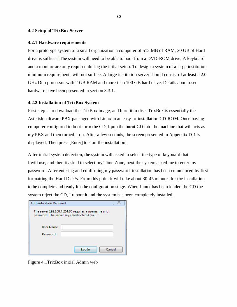
Figure 4.1TrixBox initial Admin web ........................................................................................ 30
Figure 4.2 TrixBox initial settings ............................................................................................. 31
Figure 4.3 Network configuration interface ............................................................................... 31
Figure 4.4 Adding extensions to PBX........................................................................................ 32
Figure 4.5 Created extensions saved in .CSV file ...................................................................... 32
Figure4. 6 Uploading the CSV file ............................................................................................ 33
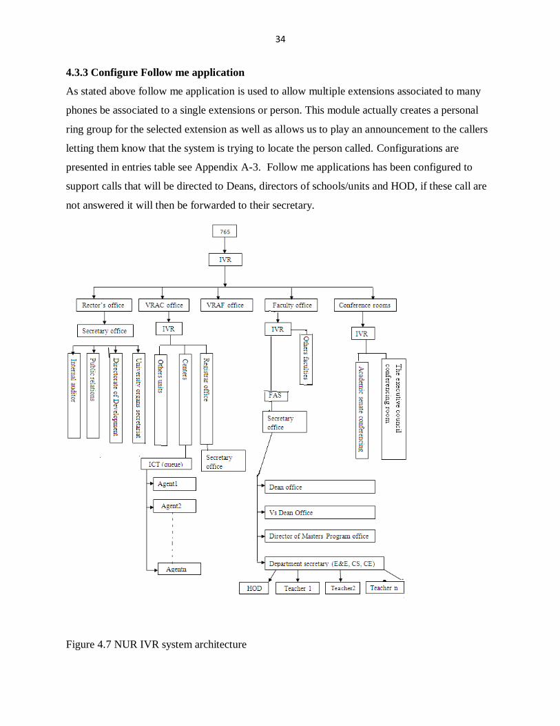
Figure 4.7 NUR IVR system architecture .................................................................................. 34
Figure 4.8 Conference room settings ......................................................................................... 35
Figure 4.9 Sample of NUR network architecture ....................................................................... 36
Figure 4.10 Client <Aheza>1100 calling1005 ........................................................................... 36
Figure 4.11 Abdul is answered .................................................................................................. 37
Figure 4.12 Wireshark screenshot when RTP packets are filtered .............................................. 38
Figure 4.13Delay and jitter Vs packet sequence when only voice is transmitted ........................ 38
Figure 4.14 Delay and jitter Vs packet sequence when voice&video are transmitted.................. 39
Figure 4.15 Flash Operator Panel .............................................................................................. 40
Figure 4.16 Call statistics .......................................................................................................... 40
Page 14
xiii
List of Tables
Table 4.1 Follow me planning ................................................................................................... 27
Table 4.2 Ring group planning .................................................................................................. 28
Table 4.3 Call center settings..................................................................................................... 28
Table 4.4 Conference room settings .......................................................................................... 29
Table 4.5 Summary of QoS tests ............................................................................................... 39
Page 15
xiv
Abstract
Voice over Internet Protocol (VoIP) has become a key technology of communication. This
research aims to the development of a VoIP system based on Asterisk, to work on NUR
(National University of Rwanda) network. After studying and analyzing the features, the
maximum number of clients, and the monthly bills of the existing telephony system i.e. NUR
PBX (Private Branch eXchange), the research has been focused on necessity to deploy a NUR
VoIP system.
After those studies we find that this analog PBX is expensive and lacks some flexibility. These
results have permitted us to develop a VoIP system based on TrixBox (Asterisk, CentOS,
FreePBX,…. ). A prototyping method has been used to develop a NUR VoIP system. This
system provide different telephony features such as Voice and Video calls, Voicemail, ring
group, IVR (Interactive Voice Response), queuing, call parking & transfer, finally the system has
been configured to provide conferencing application. QoS metrics calculations and verifications
have been conducted in order to verify that NUR IP (Internet Protocol) network can support
VoIP communication.
The said system provides a Graphical User Interface, usable when the administrator wants to
configure or manage the VoIP system. The research ends with a conclusion and
recommendation, through this stage we suggest that private and public institutions in Rwanda
can use this VoIP system in order to reduce monthly bills paid on telecommunications services
Page 16
1
Chapter1. Introduction
1.1 Background
In today’s networking and telecom industry, the buzzword is IP telephony. Many see it as a major
evolutionary step in telecommunications. This technology uses the IP to transport voice signals
over a data network. Instead of using the conventional analog voice signal (sine wave signal),
human speech is converted into a digital signal (1s and 0s) just like the data packets that travel
through the data network.
IP telephony referred to VoIP (Voice over Internet Protocols) is more revolutionary than
evolutionary because it merges two very different yet critical worlds; voice telephony (highly
cost sensitive; needs rock-solid reliability); and data networks (accept occasional failures; subject
to rapid change; need a lot of bandwidth).
A solution that merges these two worlds must simultaneously offer reliability, cost effectiveness,
a high data rate and the ability to evolve quickly. Because of the stated features that VoIP is
offering many institutions are adding to or converting their existing telephone systems to voice
over data network capabilities and gain in turn a much lower costs for the same service, better
control of communications services and new revenue producing services[1].
NUR (National University of Rwanda) has already a data communications system or high-speed
Internet connections, it does not cost much more to make calls through this data networks to
reach telephones. This is helpful because transferring voice calls over data networks can save
70% or more compared to traditional telephone service [1], it is possible to use NUR existing
telephone systems and methods of calling, even if the host to call is not directly connected to
your network, it is possible to use gateways to connect your voice over data call to the public
telephone network and it is also possible to directly communicate with remote offices or hosts.
Through this project we develop and implement a technology to establish VoIP communication
for NUR. A VoIP server based on Asterisk (Asterisk was created in 1999 by Mark Spencer of
Digium. Like any PBX, it allows attached telephones (hard phones & softphones) has been used
Page 17
2
in order to permit making calls to one another, and to connect to other telephone services
including the public switched telephone network [2] and VoIP services. Students and stuffs will
have access to this new technology and use different services such that they can make calls, and
use different features like Voicemail, video calls, call group, queuing, IVR (Interactive Voice
Response) and conferencing call, features that a configured Asterisk server can offer.
1.2 Problem Statement
Academic institutions like NUR are often challenged by the high cost and lack of flexibility of
ordinary telephone systems. Often, there are many communication costs related to the
management and implementations of programs for academic institutions. Due to the global
financial crises, these costs become an additional burden on already heavy load of academic
institution’s budget.
NUR call plan is just using public line and analog server which belongs to telephone service
providers, to interconnect its branches. In fact the issue of making call through those public lines
imposes a high monthly cost. Servers are not customizable and it is offering less features than the
Asterisk VoIP severs we want to deploy. Probably most NUR student and stuffs have a high
speed internet connection (gift from H.E President Paul KAGAME) and some of them have
laptops and PC (Personal Computer).
Therefore the aim of this project is to develop a communication technology to interconnect those
hosts which are in different NUR departments. This new technology will permit NUR
networking and communication department to deliver low cost telephone calls, voicemail, ring
groups, call transfer, conferencing, IVR and other telephony services to its clients i.e. students
and stuffs.
1.3 Research hypothesis
The availability of high speed internet connection and real-time protocols used; to initialize,
transport and terminate communication sessions, can permit to NUR to implement a VoIP
system that can be used to transmit voice and video calls on IP networks. Based on this
technology, NUR telephony system can gain more telephony features like IVR, conferencing
calls, video calls etc…. as those one that PBX can offer.
Page 18
3
Telephony services based on VoIP technology can offers to NUR more advantages such as a
flexible VoIP server, reduction of monthly bills paid on telephony calls.
1.4 Objectives
The main objective of this project is to develop an operational Internet telephony system for
NUR staffs and students, based on a software implementation of a telephone PBX running a
Linux distribution server and Asterisk.
Our target is to demonstrate that VoIP technology can be implemented by public and private
institutions so that they cannot waste their money using legacy PBX.
Through this project, professional capacity in what we learned in Electronics and
Telecommunication Engineering undergraduate will be improved. It will also help to improve
my networking and telephony technologies and new skills that will help me throughout my
engineering career.
1.5 Scope of the project
Design an operational server based on Asterisk.
Design a VoIP network based on the above server in which hosts in different NUR
departments can call each other with softphones, IP phones and with traditional phones.
Design a system offering conferencing and voicemail, call center (queuing) applications.
1.6 Interest of the project
The following paragraphs describe my personal and global interests;
Through the development of this project we will gain new and more skills related to
telecommunication and networking services.
To improve knowledge in courses I learned in class.
If this project is considered favorably, NUR institution will gain a new and cheaper
powerful communication system, so that they can use it to reduce the monthly bill cost
for telephone calls.
Page 19
4
Public and private institutions in Rwanda can develop the same system to make smarter
their phone systems.
1.7 Organization of the project
The project is divided into five chapters:
The first chapter provides for the General Introduction to the project; it includes the background
of VoIP technology, problem statement, hypothesis, main objective, scope and interest of the
project.
The second chapter gives details of VoIP technology and protocols, VoIP servers, end user
devices and it also present related project to this work.
The third chapter provides the research methods used to collect data, info about the used VoIP
server, Hardware and software tools used to deploy the VoIP services and finally the estimation
of QoS of VoIP.
The fourth chapter describes the design, the deployment and the testing of the project.
The fifth chapter presents the conclusion and recommendation.
Page 20
5
Chapter 2.VoIP Technology and Protocols
This chapter deals with theoretical concepts and fundamentals which have been taken into
consideration to support the achievement of this project. It starts with an introduction to
telephony and the conversion from analog to digital telephony. It also gives details on VoIP
standards and protocols and codecs that will be used. Finally it provide a description of
technology that can be used to deploy VoIP telephony system, and gives details on device that
ends users can use to enjoy features that the VoIP server provides. In order to a better
understanding this chapter provides terminology, definitions and characteristics of used
technologies.
The aim of this project is to design and test a VoIP system for NUR, related works have been
done and has been focused on configuration of some features like conferencing and Video calls
and other its task was to prove if VoIP network can be implemented on NUR LAN. At the end of
these works there is a recommendation of delivering a VoIP system based on Asterisk and which
has a Graphical User Interface (GUI) usable when configuring the VoIP server [3] [4].
The target of this project is to design and test a complete VoIP system with all features that a
legacy PBX can offers; the deployed system also provides features like Voice calls, Voicemail,
IVR , conferencing, video calls, ring group, call parking and finally the system will works as a
call center switch for NUR computing center. Next sections present details on basic telephony,
VoIP standards and protocols, types of VoIP servers and end users devices.
2.1 Telephony
The first voice transmission, sent by Alexander Graham Bell, was accomplished on 10th March,
1876, gradually evolved from a one-way voice transmission to a bi-directional voice
transmission. Moving the voices across the wire requires a carbon microphone, a battery, an
electromagnet, and an iron diaphragm and a physical cable between each location that the user
wanted to call. Since the invention of Gram the structure of wireline telephone network doesn’t
change significantly. In the following paragraphs we focus on telephony network and the PBX
that traditional telephone systems run on.
The acronym PSTN stands for Public Switched Telephone Network. PSTN is the network that
traditional phone systems used and was generally controlled by the telecommunication
Page 21
6
companies. This is the network our calls are travelling over when we pick up our handset and
dial a number. This network spans the world and there are many different interfaces to it;
POTS stand for Plain Old Telephone Service. It is commonly used for residential use.
POTS is an analogue system and is controlled by electrical loops.
ISDN(Integrated Services Digital Network): This is a faster and more feature-filled
connection (also more expensive) This gained some popularity within small to medium-
sized business as a cost-effective way of connecting to the PSTN and getting some
advanced services, like many lines to one office or voice and data lines on one service.
ISDN is a digital service and offers a few more features over POTS [5].
T1/E1 is a digital service used for high-volume data and voice networks and offers yet
more features than ISDN, the most important feature being increased bandwidth that
translates, in telephony, to more telephone lines [5].
A PBX is a telephone exchange that serves a particular business or office. PBXs are also referred
to as PABX (Private Automatic Branch eXchange) or EPABX (Electronic Private Automatic
Branch eXchange), PBXs make connections among the internal telephones of a private
organization and also connect them to the PSTN via trunk lines. Because they incorporate
telephones, fax machines, modems, and more, the general term "extension" is used to refer to any
end point on the branch [6].
Analog transmission of human voice signal is challenged by the fact that all sorts of thing can
interfere with those signals, which result in low volume and other undesired effects. Instead of
sending analog signal over long distance (because it can’t reach the receiver without being
disturbed) it is possible to measure the characteristic of the original sound and send that
information to the destination [7].
This is the principle of all digital audio (including telephony): sample the characteristics of the
source waveform, store the measured information, and send that data to the far end. Then the far
end uses the transmitted information to generate a completely new audio signal that has the same
characteristics as the original. The reproduction is so good that the human ear can’t tell the
difference.
Page 22
7
The principle advantage of digital audio is that the sampled data can be mathematically checked
for errors all along the route to its destination, ensuring that a perfect duplicate of the original
arrives at the far end. Distance no longer affects quality, and interference can be detected and
eliminated [7].
2.2 VoIP Standards and Protocols
The technology of VoIP uses the Internet Protocol to transmit voice as packets over an IP
network. This implies that VoIP can be implemented on any data network that uses IP, like
Internet, Intranets and Local Area Networks (LAN). In this technology voice signal is digitized,
compressed and converted to IP packets and then transmitted over the IP network. Signaling
protocols are used to set up and tear down calls and carry information required to locate users.
To make VoIP popular; products from different vendors need to operate with each other to grant
the interoperability, to achieve this task different standards are now being invented. The most
common standards for VoIP are the Session Initiation Protocol (SIP) and H323 [8]. The
following paragraphs present a description of those standards which support VoIP.
Figure 2.1 displays the setup of a VoIP system and how audio signals are processed by it.
Figure 2.1 Processing of audio signals in a VoIP system [8]
At the sender the digitized voice of the speaker is encoded by a speech encoder, and then packets
are sent through the protocol stack. If the speaker is silent, the Voice Activity Detection (VAD)
recognizes this and a packet without payload or no packet is generated. Afterwards the packets
Page 23
8
are sent over the network, for instance an IP-based LAN. At the receiver side the protocol stack
processes the packets. Then lost packets are detected and substituted. Since the packets might not
arrive in a constant flow, they are collected in a jitter buffer that adjusts time differences and the
arrival order. Finally the decoder decodes the packets and outputs them via the sound system [8].
There are a number of standards used for signaling, speech coding and the transport of the voice
packets over IP. This modularization makes VoIP flexible and the standards interchangeable
when new requirements and applications emerge. The following sections will give an
introduction to the most important standards (protocols) and issues related to VoIP.
2.2.1 Standards and Protocols
IP telephony requires some protocols for establishing and controlling the connection, which is
signaling the connection. Among them, the most popular protocols are SIP and H.323. Both
technologies use Real time Transfer Protocol (RTP) protocol to the multimedia data transport.
2.2.1.1 RTP protocol
The RTP protocol is a real time protocol which is oriented to the transmission of information in
real time such as voice or video. This protocol is a user session protocol which relies on User
Datagram Protocol (UDP), making use of the checksum and multiplexing services to allow
programs which make transmission of this kind of data handling the real time unicast or
multicast transmissions. RTP does not in itself guarantee real-time delivering of multimedia data.
The tool that RTP uses to achieve real time transmissions is the Real Time Control Protocol
(RTCP), which provides a feedback about some control information. With this, it is possible to
monitor the quality of the transmission and also possible to diagnose possible network problems.
RTP consists of four main fields; the detail of these fields is described below [9]:
RTP Payload type indicates the specific media encoding, which codec to use. The codec
conveys the type of the data (such as voice, audio or video) and how it is encoded. It can be
changed if it has to adapt the variation in bandwidth, frame indication, which marks the
beginning and end of each frame.
Sequence number helps the receiving end to reassemble the data and detect lost, out-of-order
and duplicate packets.
Page 24
9
Time Stamp, It is used to reconstruct the timing of the original audio and video. It also helps the
receiving side determine variations in packet arrival times, known as jitter. It is the time stamp
that brings real value to RTP. At receiving side each packet is compares with time stamp to make
RTP transmission possible.
Source ID, It is used to distinguish among multiple, incoming streams by the software at the
receiving side.
In this project work, RTP is used as voice streaming protocol to send real-time traffic.
To place a call on the data network, VoIP involves two types of protocol; call setup protocols
and voice streaming protocols. Call setup protocols are available to serve as the VoIP signaling
protocol, SIP, H.323 and IAX (Inter Asterisk eXchange) are most common choices. In the next
paragraphs the focus is on those signaling protocols.
2.2.1.2 Session Initiation Protocol (SIP)
SIP is an Internet Engineering Task Force (IETF) defined signaling protocol, widely used for
controlling multimedia communication sessions such as voice and video calls over Internet
Protocol. The protocol can be used for creating, modifying and terminating of multimedia
communication sessions between end users. Session is considered to be communication states
kept between senders and receivers during the communication [10].
Figure 2.2 SIP Distributed Architecture [9]
Examples of communication sessions are Internet telephone calls, distribution of multimedia etc.
The modification can involve changing addresses or ports, inviting more participants, and adding
Page 25
10
or deleting media streams. SIP clients typically use TCP (Transmission Control Protocol) or
UDP on port numbers 5060 and/or 5061 to connect to SIP servers and other SIP endpoints. Port
5060 is commonly used for non-encrypted signaling traffic whereas port 5061 is typically used
for encrypted traffic. In the next paragraphs, the structural, functional and characteristics features
of SIP are explained in detail [10].
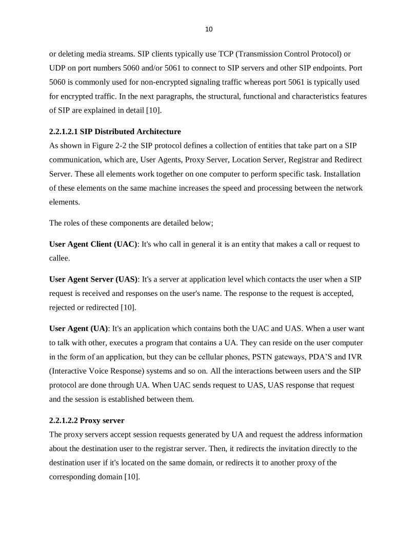
2.2.1.2.1 SIP Distributed Architecture
As shown in Figure 2-2 the SIP protocol defines a collection of entities that take part on a SIP
communication, which are, User Agents, Proxy Server, Location Server, Registrar and Redirect
Server. These all elements work together on one computer to perform specific task. Installation
of these elements on the same machine increases the speed and processing between the network
elements.
The roles of these components are detailed below;
User Agent Client (UAC): It's who call in general it is an entity that makes a call or request to
callee.
User Agent Server (UAS): It's a server at application level which contacts the user when a SIP
request is received and responses on the user's name. The response to the request is accepted,
rejected or redirected [10].
User Agent (UA): It's an application which contains both the UAC and UAS. When a user want
to talk with other, executes a program that contains a UA. They can reside on the user computer
in the form of an application, but they can be cellular phones, PSTN gateways, PDA’S and IVR
(Interactive Voice Response) systems and so on. All the interactions between users and the SIP
protocol are done through UA. When UAC sends request to UAS, UAS response that request
and the session is established between them.
2.2.1.2.2 Proxy server
The proxy servers accept session requests generated by UA and request the address information
about the destination user to the registrar server. Then, it redirects the invitation directly to the
destination user if it's located on the same domain, or redirects it to another proxy of the
corresponding domain [10].
Page 26
11
2.2.1.2.3 Registrar Server
Registrar server is a logical SIP entity that accepts the registration requests from senders extract
registration information about current location (IP address, port and username) and store that
information into location database. At the completion of registration process, Registrar Server
sends the ACK 200 message to the requestor. Registrar is very important entity that helps in
storing current information in location database, which further use for forking by proxy or
redirect server [11].
2.2.1.2.4 Location Server
A location server is a SIP entity used by a proxy and redirect server to obtain the information
about the called party possible location. Location server stores the current location of the users
by registration process.
2.2.1.2.5 Redirect Server
A Redirect server is a user agent server that accepts and receive SIP request. Redirect server
checks the request from the location database and creates the list of current location of the user
and send back the request to the originator within a 3xx response (detail in next section). The
user receives the list of current destinations and send request directly to required destination.
A general SIP transaction model consists of sequence of SIP messages (request and responses)
between SIP network elements; which describe the SIP calls setup and teardown process.
Sequence of requests and their responses are used in number of steps to complete the call
process[11].
2.2.1.2.6 SIP messages
SIP is a text-based protocol with syntax similar to that of Hyper Text Transfer Protocol (HTTP).
There are two different types of SIP messages: requests and responses. The first line of a request
has a method, defining the nature of the request, and a Request-URI (Uniform Resource
Indictor), indicating where the request should be sent. The first line of a response has a response
code [10]. Method is an important entity in the request line and used to decide the function of
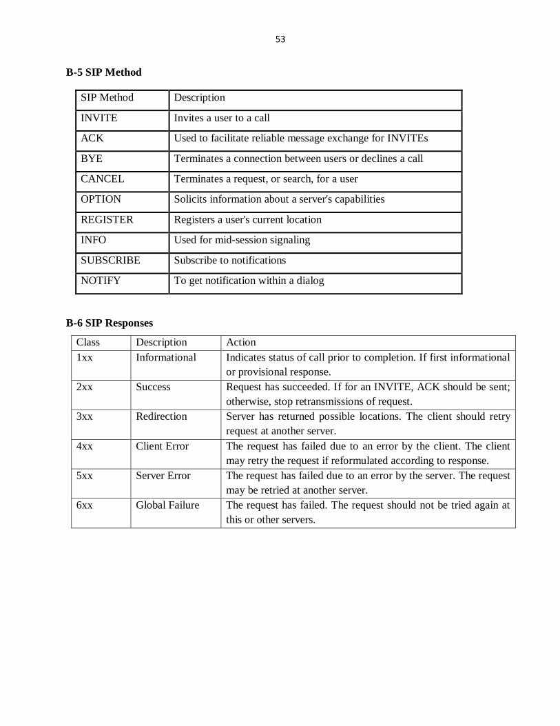
request, six types of methods are defined: REGISTER, INVITE, ACK, CANCEL, BYE,
OPTIONS. Appendix B-5 presents details on these methods;
Page 27
12
2.2.1.2.7 SIP Responses
Every request needs a response, when a user agent receives a request it replies the response.
Response methods are similar to request, except to the first line. First line of the response
contains protocol version (SIP/2.0), reply code, and reason phrase. The reply code is integer
number from 100 to 699 and indicates type of response. These 6 classes of responses are
explained in B-6.
2.2.1.3 H.323 protocol
H.323 is a recommendation from the ITU Telecommunication Standardization Sector (ITU-T)
that defines the protocols to provide audio-visual communication sessions on any packet
network. The H.323 standard addresses call signaling and control, multimedia transport and
control, and bandwidth control for point-to-point and multi-point conferences.
It is widely implemented by voice and videoconferencing equipment manufacturers, is used
within various Internet real-time applications and is widely deployed worldwide by service
providers and enterprises for both voice and video services over IP networks.
Within the context of H.323, an IP-based PBX might be a gatekeeper or other call control
element which provides service to telephones or videophones. Such a device may provide or
facilitate both basic services and supplementary services, such as call transfer, park, pick-up, and
hold [12].
N.B: SIP has pretty much dethroned the once-mighty H.323 as the VoIP protocol of choice
certainly at the endpoints of the network. The premise of SIP is that each end of a connection is a
peer; the protocol negotiates capabilities between them. What makes SIP compelling is that it is a
relatively simple protocol, with syntax similar to that of other familiar protocols such as HTTP
and SMTP (Simple Mail Transfer Protocol) [12].
2.2.1.4 IAX (The “Inter-Asterisk eXchange” Protocol)
The IAX protocol was developed by Digium for the purpose of communicating with other
Asterisk servers (hence the Inter-Asterisk eXchange protocol. The standard is open for anyone to
use, and it is supported by many other open source telecom projects, as well as by several
hardware vendors.
Page 28
13
IAX is a transport protocol (much like SIP) that uses a single UDP port (4569) for both the
channel signaling and media streams, this makes it easier to manage it when behind NATed
(Network Address Translator) firewalls.
IAX also has the unique ability to trunk multiple sessions into one dataflow, which can be a
tremendous bandwidth advantage when sending a lot of simultaneous channels to a remote box.
(Trunking allows multiple media streams to be represented with a single datagram header that
will lower the overhead associated with individual channels. This helps to lower latency and
reduce the processing power and bandwidth required, allowing the protocol to scale much more
easily with a large number of active channels between endpoints.) If you have a large quantity of
IP calls to pass between two endpoints, you should take a close look at IAX trunking.
As security consideration IAX includes the ability to authenticate in three ways: plain text, MD5
(Message Digest Algorithm) hashing, and RSA (Rivest Shamir and Adleman) key exchange.IAX
is the best protocol [12].
2.2.2 Codecs
Codecs are generally understood to be various mathematical models used to digitally encode
(and compress) analog audio information. Many of these models take into account the human
brain’s ability to form an impression from incomplete information. Originally, the term codec
referred to a COder/DECoder: a device that converts between analog and digital. Now, the term
seems to relate more to COmpression/DECompression.
2.2.2.1 Voice Companding
Companding refers to the process of first compressing an analog signal at the source, and then
expanding this signal back to its original size when it reaches its destination. At the time of the
companding process, input analog signal samples are compressed into logarithmic segments.
Each segment is then quantized and coded using uniform quantization. The compression process
is logarithmic. The ITU−T standards for companding are called A−law and u−law [9].
A−law and u−law are audio compression schemes (codecs) defined by Consultative Committee
for International Telephony and Telegraphy (CCITT) G.711. A−law and u−law are referred to
codec G.711.
The signaling functionality of this codec is described below,
It uses the frequency range of 4 kHz to capture the human voice conversation.
Page 29
14
To capture the proper degree of resolution, the voice information is sampled at double the
frequency range, or 8000 times per second. Thus PCM grabs the chunk of data every
0.125 ms i.e. (1 second / 8000*0.000125 seconds)
Each sample occupies 8 bits of data, so the overall bandwidth required is (8000 * 8), or
64000 kbps [9].
2.2.2.1.1 A−law
The A−law compression is defined by the following equation, where A is the compression
parameter (A=87.7 in Europe), and x is the normalized integer to be compressed.
[9] (2.1)
2.2.2.1.2 µ −law
The µ −law is defined by the following equation, where m is the compression parameter (µ =255
in the U.S. and Japan) and x is the normalized integer to be compressed. A−law standard is
primarily used by Europe and the rest of the world. µ −law is used by North America and Japan.
[9] (2.2)
2.2.3 Asterisk Private Branch eXchange
Asterisk is an open source, converged telephony platform, which is designed primarily to run on
Linux. Asterisk was created in 1999 by Mark Spencer of Digium. Like any PBX, it allows
attached telephones (hard phones & softphones) to make calls to one another, and to connect to
other telephone services including the public switched telephone network and VoIP services. Its
name comes from the asterisk symbol. Asterisk was designed to replace traditional PBX, which
means it performs all the features and functionality related to normal PBX does [12]. For
interconnection between digital and analog telephony equipment, Asterisk does Voice over IP in
many protocols, call setup and voice streaming protocols are example. It provides transport
Page 30
15
bridging between Voice over IP protocols including SIP, H.323, IAX, Media Gateway Control
Protocol (MGCP), and also support traditional circuits like TDM, T1/E1, POTS, BRI and PRI
[13]. The Asterisk software includes many features available in proprietary PBX systems: voice
mail, video call conference calling, interactive voice response (IVR), and automatic call
distribution. Users can create new functionality by writing dial plan scripts in several of
Asterisk's own extensions languages, by adding custom loadable modules written in C, or by
implementing Asterisk Gateway Interface (AGI) programs [14].
2.2.3.1 Asterisk Architecture
Asterisk is designed for maximum flexibility and interconnection. As shown in Figure 2.6 the
Asterisk core contains several engines that each plays a critical role in the software’s operation.
Figure 2.3 Major Asterisk Subsystems [12]
Firstly, when Asterisk is started, the Dynamic Module Loader loads and initializes each of the
drivers, which provide channel drivers, file formats, call detail-record back ends, codecs,
applications and more, linking them with the appropriate internal Application Programming
Interface (API). Then, Asterisk’s PBX switching core begins accepting calls from interfaces and
handling them according to the diaplan, using Application Launcher for ringing phones,
connecting to voicemail, etc. Scheduler and I/O Manager is a core component engine that
provides environment to applications and drivers to take advantage of Asterisks. Finally
Asterisk’s Codec Translator permits channels which are compressed with different codecs to
seamlessly talk to one another [14]. Channel API Channels are the logical entities use to connect
Page 31
16
signaling and transmission path between end points. All calls arrive at or leave an Asterisk server
through an interface, for example SIP, Zaptel or IAX. Any incoming or outgoing call is made
through an interface.
Every call is placed or received over an interface on its own distinct channel. A channel can be
connected to a physical channel like a POTS line, or to a logical channel like an IAX or SIP
channel. If a call arrives at Asterisk over a channel, a dial plan determines what is done with the
call. For example, a call might arrive through a SIP channel. The call could be coming from a
SIP telephone, or from a SIP soft phone running on a computer. The dial plan determines if the
call should be answered, connected to another telephone, forwarded or directed to voice mail.
Asterisk provides various applications, for example voice mail. These applications are available
to the dial plan when processing the incoming call. The dial plan and the applications selected
for use within the dial plan determine what Asterisk does [14].
2.3 VoIP Servers and End Users
To establish calls clients will first be registered to the VoIP server. They are many type of VoIP
servers, this section give details on type of VoIP servers and type of devices that end users will
used in other to be registered.
2.3.1 3CX Phone System for Windows
3CX Phone System works with popular VOIP Gateways, SIP trunking providers and SIP phones
to allow you to setup a complete IP PBX in a matter of half an hour. 3CX’ SIP server is quickly
downloaded and installed and runs on all popular versions of Windows, including XP, Vista, 7,
2003 server and 2008 server. Configuration is performed via an easy to use Web interface. 3CX
Phone System has withstood rigorous quality testing and was award the “Certified for Windows
2003” Logo [15].
2.3.2 Pure Asterisk
Asterisk is “Open Source PBX software” that once installed in Personal Computer (PC)
hardware along with the correct interfaces, can be used as a full featured PBX for home users,
enterprises, VoIP service providers and telecoms. For more details see section 2.2.3.
Page 32
17
2.3.3 Customized Linux Distributions
There are various distributions such as AsteriskNow, Elastix, TrixBox, FreeSwitch, SER,
OpenSIPS, etc. But the most popular are the first three. In the following paragraphs I present a
short description of each.
AsteriskNow is an open source software appliance, a customized Linux distribution that
includes Asterisk, the Asterisk GUI, and all other software needed for an Asterisk system. The
Asterisk GUI gives you the ability to easily configure your Asterisk system without being a
technical expert.
Elastix is an open source Unified Communications Server software that brings together IP PBX,
email, IM, faxing and collaboration functionality. It has a Web interface and includes capabilities
such as Call Center software with predictive dialing [16].
TrixBox: TrixBox, a Fonality product is composed of Asterisk and some of its most popular
features combined on a ready-to-install ISO (International Organization for Standardization).
TrixBox platform is the open source software. TRIXBOX evolved from the core Asterisk. It is
made up of several major components; more details are presented in the next chapter. These were
developed under GPL supported relatively by users themselves. It consists of applications, a
provisioning system, an installer, and an operating system that, together, make a complete
package ready for use as an out of the box PBX[17]. The above paragraphs show that TrixBox is
the best to use because it offers a system full of many features. By using this I will gain more
skills in Linux and telephony concept.
2.3.4 Client Sides
In the development of this project; end users uses softphones, IP phones and traditional
telephones in order to make calls to each others. Using traditional telephones on VoIP network
requires some ATAs (Analog Telephone Adapters) that will permits the conversion from analog
(voice signal) to digital packet of data and sends it over the internet. IP phones will be connected
to the network via an Ethernet cable.
And finally softphones (SIP or IAX software) installed on client computer; it acts as telephone. It
requires a fast Ethernet connection, a soft phone, a speaker, microphone and sound card, to make
and receive the calls.
Page 33
18
Chapter3. Method for data collection, Tools and QoS metrics
Methodology is a system of broad principles or rules from which specific methods or procedures
may be derived to interpret or solve different problems within the scope of a particular kind of
work. Research methods refer to a number of ways of arriving at the knowledge regarding that
research. This chapter discusses method and technique used in data collection, data analyzing,
result interpretation and the description of the area and the environment of interest i.e. the
National University of Rwanda, it also provides method used to build the system and finally it
present method for enhancing VoIP QoS (Quality of Service) of calls.
3.1 Data collection
In the following paragraphs I describe different process used in gathering information of interest.
3.1.1 Gathered Documents
Library method consists of any reading or printed material they may expand one’s knowledge in
connection, which study being held. Gathering of data provides the researcher with vital
information in the development of the study, books and previously written project provided the
researcher with ideas that were helpful in the development of the propose system. (The
researcher have visited different libraries a have thorough research and also read different
materials that are relevant to the study being conducted.)
This method has been used in order to choose the best-printed materials from those gathered that
would best serve in helping out me in developing the desired system.
3.1.2 Investigation Techniques
To get a better understanding of the requirements and the problem domain, different approach
has been adopted in order to accomplish the target of this project.
3.1.3 Interviews approach
We adopt this technique in order to know the background of NUR campus; this approach
enabled us to know the existing and present problems of NUR telephony system. It has also
helped me as a data collection method; it is a face to face conversation between the interviewer
and the respondent conducted for obtaining information, this method assumes that the respondent
interviewed has the required information . It was done with the NUR PBX manager.
Page 34
19
We was privileged enough to speak with him. He said that NUR institution is now using Alcatel
PBX in order to establish call between NUR employees. Besides of the non-customization and
high cost of the said system compared to a VoIP system, results are unsatisfying because the said
system cannot offer telephony features like call queuing, call recording, video call, IVR etc. It is
important to say that this system serves only employees whereas students cannot use it.
A collecting data technique used is structured interview (Appendix B-1). To this end, a number
of interviews were conducted at NUR Huye branch in order to get input from some staffs.
3.2 Information of the TrixBox CE open source IP PBX system
TrixBox is a collection of telecommunication utilities and tools compiled together to become an
integrated IP PBX. The major components that make up TrixBox are;
• Asterisk, the core PBX
• Sugar, a CRM system
• A2Billing – Calling Card platform
• Flash Operator Panel, a screen-based operator’s console
• Web Meet Me Control, a meet me conferencing control application
• FreePBX a web-based User Interface tool for TrixBox.
• A report system – the part of freePBX that provides CDR reporting.
• CentOS, a version of Linux (but without the branding and support).
In order to set up a VoIP network based on asterisk 3 main components are required, such as:
TrixBox, the Asterisk powered IP PBX, The phones (or softphones) and have access to a
broadband Internet connection [18].
3.3 Tools
Through the development of this project, the following hardware and software tools have been
used;
3.3.1 Hardware
DELL OPTIPLEX 360 DESKTOP( 1GB RAM)
HP 620 Laptop
Headsets
Switches and Webcams
Page 35
20
3.3.2 Software
TrixBox 2.6.2.3 based on CentOS Version 5.3 with Kernel 2.6.18-128.1.10.e15
Asterisk 1.4
Various IAX2,SIP Soft phones
E-Drawer Max 4.6
Wireshark
Wireshark is a network analyzing tool; it captures the packets and displays its details, Wireshark
helps to understand what is going on in the network in real time voice call. Some of the features
of Wireshark are captures live packets, displays a detailed protocol information for the packet
captured, can save the data packets captured, can apply packet filters, performs stream analysis,
and finally it captures information like delay, jitter, bandwidth, codec etc for packets [19].
3.4 Quality of Services (QoS)
QoS is the differentiation between types of traffic and types of services so that the different types
of service and traffic can be treated differently. This way, one type can be favored over another.
The primary goal of QoS is to provide priority including dedicated bandwidth, controlled jitter,
and latency, and improve loss characteristics [20]. Real time packets such as voice and video
packets must be prioritized such that they arrive at their destination on time. Before showing how
to improve the performance of the network to insure QoS, it is important to describe the five
fundamentals network problem for VoIP.
Bandwidth is the fundamental requirement that there be enough space in a network path
for all of the packets to get through unimpeded (Not slowed or prevented).
This bandwidth need is symmetric-each end will transmit and receive this amount of
traffic [21].
Packet loss is the amount of packets that does not arrive correctly to their destination.
This is due to insufficient bandwidth or transmission errors [21].
Latency is the time delay between an event occurring on one site and the remote end
seeing it. Latency is introduced both by the encoding/decoding process, and hence
depends on the equipment used, and also by the time it takes packets to traverse the
network. A disruption in the image can cause a bad playing in the destination, but a
Page 36
21
disruption in the voice is more important since it makes the transmission not
understandable [21].
Jitter Packets from the source will reach the destination with different delays. A packet's
delay varies with its position in the queues of the routers along the path between source
and destination and this position can vary unpredictably. This variation in delay is known
as jitter and can seriously affect the quality of streaming audio and/or video [21].
N.B: Thought this project work we consider that NUR site has enough bandwidth to
accommodate voice and video traffic. While developing, my attention will be focused on
how to minimize packet loss, delay and jitter in VoIP traffic.
3.4.1 QoS requirements for Voice application
VoIP deployments require the provisioning of explicit priority servicing for VoIP (bearer stream)
traffic and a guaranteed bandwidth service for Call-Signaling traffic. Recommendations for voice
Loss should be no more than 1 percent, one-way latency (mouth to ear) should be no more than
150 ms., average one-way jitter should be targeted at less than 30 ms and a range of 21 to 320
kbps of guaranteed priority bandwidth is required per call (depending on the sampling rate, the
VoIP codec, and Layer 2 media overhead). Voice quality directly is affected by all three QoS
quality factors: loss, latency, and jitter [22].
3.4.2 QoS Requirements of Video application
Two main types of video traffic exist: Interactive-Video (videoconferencing) and Streaming-
Video (both unicast and multicast). We focused on interactive video.
When provisioning for Interactive-Video (video conferencing) traffic, the following guidelines
are recommended, Loss should be no more than 1 percent, One-way latency should be no more
than 150 ms, Jitter should be no more than 30 ms and Assign Interactive-Video to either a
preferential queue or a second priority queue (when supported); when using Cisco IOS LLQ,
overprovision the minimum-priority bandwidth guarantee to the size of the videoconferencing
session plus 20 percent. For example, a 384-kbps videoconferencing session requires 460 kbps of
guaranteed priority bandwidth [23].
Page 37
22
3.5 Estimation of QoS of VoIP
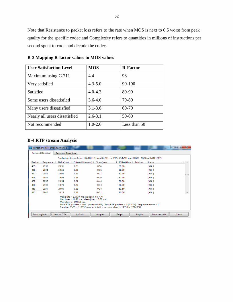
Appendix B-6 presents details about calculations of Bandwidth for G.711, the average latency ,
jitter and packet loss [24-26] using formulas. Wireshark have been used to determine those
metrics.
According to [27] many methods have been proposed by standardization forum in order to
evaluate the perceived voice quality. The most important ones are the following; Mean Opinion
Score (MOS), Perceptual Evaluation of Speech Quality (PESQ), Perceptual Speech Quality
Measurement (PSQM) and perceptual Analysis Measurement System (PAMS). MOS use
different listeners to evaluate the Distortions of the perceived voice samples. The score are
averaged to MOS value. PSQM assesses the Voice quality by comparing the perceived voice
samples against the encoding voice samples. PAMS conducts quality evaluation by employing
an auditory model. PESQ combine PAMS and PSQM techniques to generate a voice quality
score on a scare between 0.5 and 4.5. There are major drawbacks associated to the
aforementioned quality evaluation methods such as;
They are not suitable for planning and engineering, from a VoIP provider perspective.
They require a large number of heterogeneous listeners (end users) to evaluate the
perceived voice distortions.
They are receiver oriented, the quality evaluation is mainly determined at the receiver’s
end only.
To fight for the above drawbacks two models have been developed; E model for voice quality
evaluation and Gap model for video quality evaluation.
3.5.1 E-model and Gap model description
The E-model has been defined in the ITU-T G.107 [28]. It is a method for estimating the
perceived voice quality. It combines several impairment factors, caused by transmission
parameters, into a rating R and can be expressed, as the sum of four terms:
R=100 – Is - Id - Ief + A (3.1)
Is: refers to the signal to noise impairments associated with the transmission path.
Id : is the mouth to ear delay of the transmission path.
Page 38
23
Ief :is an equipment impairment factor associated with losses and the voice codecs,
A ; refers to the expectation factor.
Figure 3.1 illustrates how different VoIP parameters (codec type, packet loss, delay jitter) affect
the calculation of the R-factor.
Figure 3.1 The factors of the computation of the E-model and the R-factor [27]
The advantages of the E-model are the following:
There is no need to use the original encoded samples that are transported over the
network.
It is not necessary to use a large number of end-users with diverse characteristics.
To calculate Ief for G.711 the following formula has been proposed [28]
Ief (G.711) =30*ln (1+15*e)*H (0.04-e) +19*ln (1+70*e)*H (e-0.04) [28] (3.2)
e is the total loss probability in the path between the sender and the receiver.
According to [29] the R-factor is calculated as follows:
R=93.2 – 0.024*d + 0.11* (d-117.3) * H (d-177.3) - Ief (3.3)
Where:
d: is the one-way transmission delay between the transmitter and the receiver.
H(x): is the step function, with H(x) =
(3.4)
To calculate e and d in order to find the value of R-factor Wireshark software will be used.
Page 39
24
Finally the value for R-factor found should be mapped to MOS values.
Formula 3.5 will be used to perform the stated conversion;
MOS=1+0.035R+7*10-6
*R*(R-60)*(100-R) [29] (3.5)
Appendix B-3 is a table describing the mapping of R factor values to MOS values as stated by
ITU-T.
3.5.2 Gap model
To estimate video calls Quality of Experience(QoE) affected by network conditions, the most
widely adopted technique is the PSNR-mapped-to-MOS technique which is offline in nature, it is
developed to-date estimate VVoIP QoE by performing frame-to-frame Peak-Signal-to-Noise
Ratio (PSNR) comparisons of the original video sequence and the reconstructed video sequence
obtained from the sender-side and receiver-side, respectively. In fact PSNR is the measure of
fidelity (how close a received signal is similar to an original one), but its measures consider only
the luminance components [30].
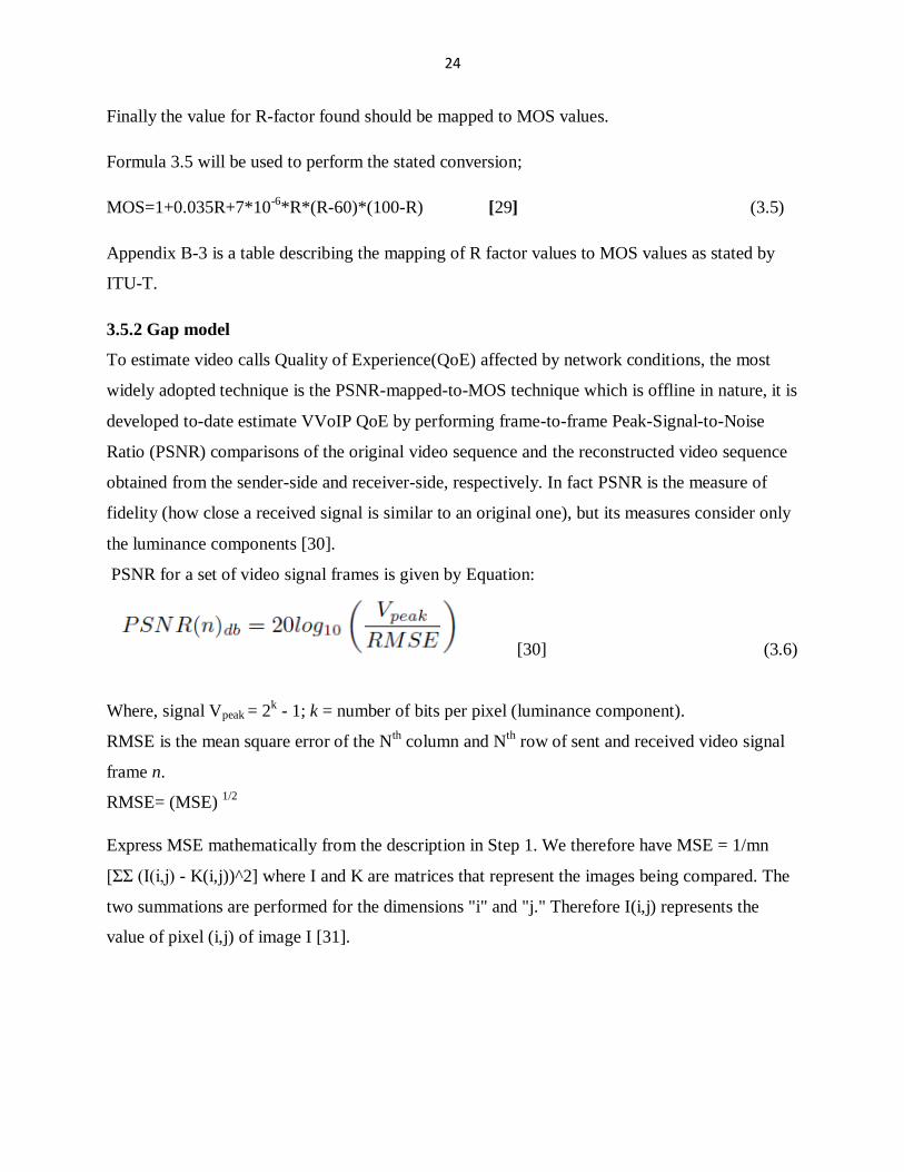
PSNR for a set of video signal frames is given by Equation:
[30] (3.6)
Where, signal Vpeak = 2k - 1; k = number of bits per pixel (luminance component).
RMSE is the mean square error of the Nth column and N
th row of sent and received video signal
frame n.
RMSE= (MSE) 1/2
Express MSE mathematically from the description in Step 1. We therefore have MSE = 1/mn
[ΣΣ (I(i,j) - K(i,j))^2] where I and K are matrices that represent the images being compared. The
two summations are performed for the dimensions "i" and "j." Therefore I(i,j) represents the
value of pixel (i,j) of image I [31].
Page 40
25
Chapter4. Design and Test of NUR VoIP System
This chapter provides a description of how a VoIP system based on Asterisk will be established
in NUR campus. Asterisk is a kind of open source software to implement IP-PBX system and
supports various necessary protocols to realize the VoIP system such as SIP and H.323. First it
deals with the planning of NUR dialplan, this is followed by the deploying of TrixBox server,
third the TrixBox configurations, and then the determination of QoS metrics and verification of
VoIP requirement if are well established in NUR network and finally the testing of the system.
4.1 Planning NUR dialplan prototype
A poorly designed system will cause numerous changes after the system has be delivered and
running. This is why during the development of this system; the planning stage has been given
much time and serious attention. The developed system comprises some telephony features.
Others features will be developed in later work, these are instant messaging, voicemail-email
notification and A 2Billing card.
4.1.1 Units of NUR
Currently, NUR is a large university offering 39 undergraduate programs and 24 postgraduate
programs with more than 12,000 students. For more detail see [31].
4.1.1.1 NUR Offices and Faculties
The Office of the Rector comprises the following:
The University organs secretariat (University Council, Academic Senate and the
Coordination Committee)
The Directorate of Development and Planning
The Public relations
Internal auditor
Office of the Vice Rector for Academic Affairs: This office controls the following units:
Academic Affairs and Registration
Faculties and schools
Page 41
26
Note that NUR has 2 schools and 7 faculties which are: School for Foundation Language Skills
School of Public Health, Faculty of Economics and Management, Faculty of Science, Faculty of
Law, Faculty of Applied Sciences, The Faculty of Arts, Media and Social Sciences, Faculty of
Agriculture, and the Faculty of Medicine.
Centers and Other units
Office of the Vice Rector for Administration and Finance: It has the following units:
Production Unit and Finance Unit
Administration and Human Resources Unit and Student Services Unit
The VoIP server will be situated (located) at NUR ICT server room. End users use IP phones,
analogue phones with ATAs and finally installation of softphones on different computers
(desktop and laptops) will be performed in order to make call by using computers. Linux and
Windows users will enjoy telephony features offered by this system.
4.1.2 Dial plan
Dial plan is Asterisk’s heart. It defines how Asterisk handles each and every call to the PBX. It
consists of extensions that make an instruction list for Asterisk to follow. This means that in
order to deliver VoIP calls to all clients at minimum each client requires one extension. The
length of those extensions will be selected according to number of stuffs in different departments
and to the number of students in different faculties. To predict about the glow of NUR institution
I have make an assumption “what I believe to use and double it” this means that where I found
that the 20 employees in departments I have to predict that in future the system will support
approximately 40 users in the concerned department.
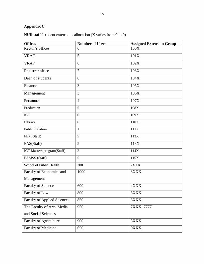
4.1.2.1 Number of users per department and their extension groups
While planning for extensions, avoid using extensions that begin with any of the numbers I may
use in my IVR menus to reduce the unwelcome delays while the system is trying to figure out if
it needs to go to a menu or an extension. The table in Appendix C presents a sample of users per
department and their extension groups. Pattern matching notation has been used to simplify the
work of writing extensions for large institution. Different extension group has been assigned to
different faculties according their users.
Page 42
27
4.1.3 VoIP features to offer
This section describes VoIP features to be configured in order to deliver a system with advanced
telephony features. I will give details on voice and video calls, Voicemail, Follow me, Ring
group, call parking and transfer, IVR, conferencing and call queues.
4.1.3.1 Voice, Video calls and Voicemail
The basic feature that a telephony system should provide is to permit clients (users) to make calls
between them. Through this project we configured video calls to be associated to voice calls. All
students and stuffs are allowed to make voice and video calls using this system. Coming sections
present how extensions will be assigned to clients.
Each extension will be associated to a mailbox, such that if the extension is dialed and it is busy
or unavailable, the caller will have a possibility to leave his message to mailbox of the callee.
4.1.3.2 Follow me
Follow me is an application that permit this system to forward a call to another extension if the
callee doesn’t pick up her/his phone. Suppose that the callee has two phones one in his office and
another in his mobile phone, application like follow me can be configured to forward call to the
mobile of the callee if his phone in the office didn’t be answered.
Follow me has been configured to allow direct calling of other extensions; planning in table 4.1.
Extensions in offices of Deans, Vice Deans, Head of Department (HOD) and offices of Directors
will be assigned to a follow me applications in other to forward calls to secretary’s offices if the
callee didn’t pick up the phone. Adopted strategy is “hunt”.
Table 4.1 Follow me planning
Chef’s office Rector VRAC Register VRAF Masters Program FAS
Secretary’s office 1002 1012 1032 1022 1042 1032
4.1.3.3 Ring group
A ring group is a group of extensions that can all be made to ring at the same time when a single
extension is called. This can be a useful feature within an organization as it allows the nearest
available user to answer the phone. Ring groups can be configured as 'ring all’, or 'hunt' when
Page 43
28
configured as ring all the incoming call will ring at each extension simultaneously, whereas a
hunt group will try ringing each extension individually.
Table 4.2 presents record of important information relating to the settings of ring groups.
Table 4.2 Ring group planning
Group Name Group
#
Ring
Strategy
Announcement CID
Prefix
N/A
Destination
Members
Financial 789 Ring-all Fntal_group FNCL 1055 1052,1053,1054
Maintenance 345 Ring-all Mtnce_group MTNCE 2000 2001,2002,2003
Helpdesk 234 Ring-all ICT_helpdesk ICT 1095 1011,1012,1013,1014
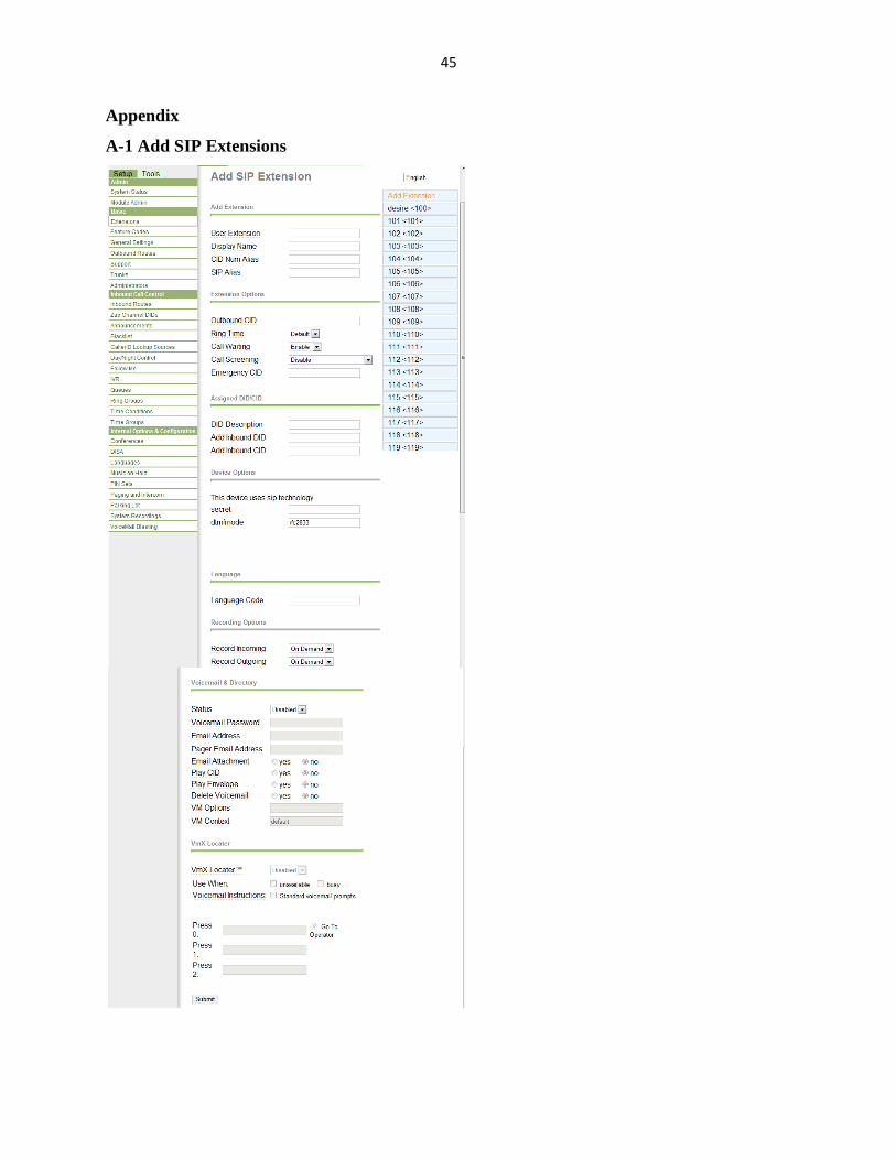
4.1.3.4 Call queuing
Call Queuing is a sophisticated queuing system that allows to a unit to accept more calls into its
telephone system than its extensions or employees capable of answering them. It permits to deal
efficiently with calling peaks without losing valued customer’s calls. With Call Queuing, instead
of getting an engaged tone your customers are answered automatically and held in a queue.
While they are waiting for an agent they receive personal messages about how many calls are in
front of them followed by music while they are waiting. Planning is in table 4.3.
In this project call queuing feature has been configured to support calls of NUR ICT center, if
extension 200 is dialed call will be directed to NUR ICT center. Helpdesk agents will be able to
answer calls which will be directed to them. Table 4.3 presents important details in order to setup
this technology.
Table 4.3 Call center settings
Queue
Name
Queue
#
Password Announcement On-Hold
Music
Category
Ring
Strategy
Static Agents
ICT 200 Xxxxxx Welcome to
NURICT center
Inherit Ring all 1011,1012,1013
1014,1015
This technology will be useful while it will reduce time spent while moving to the ICT to ask
solutions for students and stuffs problems. For a cooperative ICT queue greet with this
Page 44
29
message;“Welcome to NUR ICT center, we will deal with your inquiry later we experiencing a
high volume of calls, thanks for using this service”
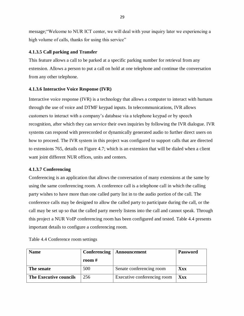
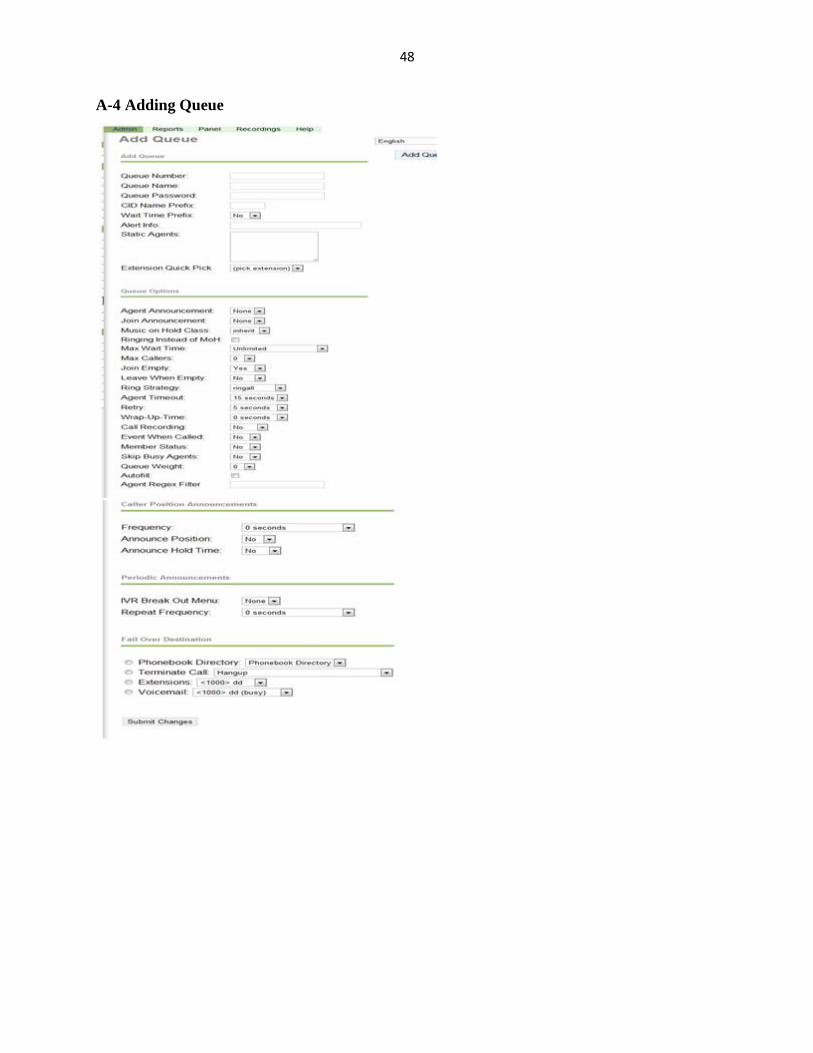
4.1.3.5 Call parking and Transfer
This feature allows a call to be parked at a specific parking number for retrieval from any
extension. Allows a person to put a call on hold at one telephone and continue the conversation
from any other telephone.
4.1.3.6 Interactive Voice Response (IVR)
Interactive voice response (IVR) is a technology that allows a computer to interact with humans
through the use of voice and DTMF keypad inputs. In telecommunications, IVR allows
customers to interact with a company’s database via a telephone keypad or by speech
recognition, after which they can service their own inquiries by following the IVR dialogue. IVR
systems can respond with prerecorded or dynamically generated audio to further direct users on
how to proceed. The IVR system in this project was configured to support calls that are directed
to extensions 765, details on Figure 4.7; which is an extension that will be dialed when a client
want joint different NUR offices, units and centers.
4.1.3.7 Conferencing
Conferencing is an application that allows the conversation of many extensions at the same by
using the same conferencing room. A conference call is a telephone call in which the calling
party wishes to have more than one called party list in to the audio portion of the call. The
conference calls may be designed to allow the called party to participate during the call, or the
call may be set up so that the called party merely listens into the call and cannot speak. Through
this project a NUR VoIP conferencing room has been configured and tested. Table 4.4 presents
important details to configure a conferencing room.
Table 4.4 Conference room settings
Name Conferencing
room #
Announcement Password
The senate 500 Senate conferencing room Xxx
The Executive councils 256 Executive conferencing room Xxx
Page 45
30
4.2 Setup of TrixBox Server
4.2.1 Hardware requirements
For a prototype system of a small organization a computer of 512 MB of RAM, 20 GB of Hard
drive is suffices. The system will need to be able to boot from a DVD-ROM drive. A keyboard
and a monitor are only required during the initial setup. To design a system of a large institution,
minimum requirements will not suffice. A large institution server should consist of at least a 2.0
GHz Duo processor with 2 GB RAM and more than 100 GB hard drive. Details about used
hardware have been presented in section 3.3.1.
4.2.2 Installation of TrixBox System
First step is to download the TrixBox image, and burn it to disc. TrixBox is essentially the
Asterisk software PBX packaged with Linux in an easy-to-installation CD-ROM. Once having
computer configured to boot form the CD, I pop the burnt CD into the machine that will acts as
my PBX and then turned it on. After a few seconds, the screen presented in Appendix D-1 is
displayed. Then press [Enter] to start the installation.
After initial system detection, the system will asked to select the type of keyboard that
I will use, and then it asked to select my Time Zone, next the system asked me to enter my
password. After entering and confirming my password, installation has been commenced by first
formatting the Hard Disk/s. From this point it will take about 30-45 minutes for the installation
to be complete and ready for the configuration stage. When Linux has been loaded the CD the
system reject the CD, I reboot it and the system has been completely installed.
Figure 4.1TrixBox initial Admin web
Page 46
31
4.3 Configuring the VoIP Server
TrixBox is configured via a Graphical User Interface (GUI), to access it just I opened my web
browser and browse the following URL:http://192.168.4.254 this one is the IP of the NUR VoIP
server prototype. TrixBox initial Admin web login screen is then presented, Figure 4.1 displays
how it looks like; my username and my password are required in order to access the
configuration mode of the VoIP server. Then the system will present its initial settings including
server status, network usage, memory usage, system uptime and the trixbox status, Figure 4.2
illustrates these settings;
Figure 4.2 TrixBox initial settings
By default the server is enabled to DHCP settings or a server requires a static IP address, this is
why I set the network card (eth0) to static mode as shown below;
Figure 4.3 Network configuration interface
4.3.1 Configuring Extensions and Voicemails
Through this project we proposed that each extension be associated to its voicemail, such that if
it is dialed when busy, it will be transferred to the corresponding voicemail. Configuring
Page 47
32
extensions of a large institution with more clients is big deal if you are just writing details of
each extension at the extension GUI. To solve this problem Bulk Extensions module has been
installed to permit me to download a file in CSV (Comma Separated Values) the one we use to
expand all extensions that will be used in dialplan. From the PBX menu I select the PBX settings
and the following interface is opened. Then choose the SIP technology and then submit it. The
configuration format of an extension and voicemail are presented in Appendix A-1. The Figure
4.4 is a snippet of a SIP device entry.
Figure 4.4 Adding extensions to PBX
From the Bulk Extensions menu, I downloaded the format of extension and voicemail
configuration. This is a CSV file, it can be opened and task like add, edit and delete (del) can be
performed on it to add/edit extensions or delete them. Then the CSV file can open/import/export
the new file to the server.
The figure 4.5 displays a list of created extensions.
Figure 4.5 Created extensions saved in .CSV file
From this guide it is possible to setup the rest of extensions by using tools that are included in the
spreadsheet. Figure 4.6 shows how the uploading of a CSV file to the server is performed.
For fields which are common for all users, it is possible to select and drop, by the way in case of
Excel, as you drag and drop it will increment the number (extensions in our case).
Page 48
33
Figure 4.6 Uploading the CSV file
After edit the file, use the Bulk Extensions menu to choose it from other files and load the file to
the server.
To configure video call we need to edit Asterisk configuration file especially
sip_additional.conf, I add in, the following lines of code;
[general]
Videosupport= yes
And then for each extensions configured in this file I add these lines of codes to be used as video
codecs;
allow=h263; H.263 is our video codec
allow=h263p; H.263p is the enhanced video codec.
4.3.2 Configure ring group application
Used to ring multiple extensions at the same time, it was configured to support calls that are
directed to specific units and each member of the unit can pick up the phone. Details see
Appendix A-2.
Page 49
34
4.3.3 Configure Follow me application
As stated above follow me application is used to allow multiple extensions associated to many
phones be associated to a single extensions or person. This module actually creates a personal
ring group for the selected extension as well as allows us to play an announcement to the callers
letting them know that the system is trying to locate the person called. Configurations are
presented in entries table see Appendix A-3. Follow me applications has been configured to
support calls that will be directed to Deans, directors of schools/units and HOD, if these call are
not answered it will then be forwarded to their secretary.
Figure 4.7 NUR IVR system architecture
Page 50
35
4.3.4 Configure queuing
Queues give us a logical place to put callers until we are ready to answer the calls. Queues are a
very flexible and powerful tool to improve customer service, and better utilize our personnel. In
this project I configured NUR ICT center to work as a call center for NUR. Helpdesks in ICT
will work as agents ready to answers calls from different NUR staffs and students. The system
should provide announcement to callers and their positions in the queue. See configuration in
Appendix A-4. Figure 4.7 present a flow chart that describes how ICT call center will be
reached.
4.3.5 Conference Rooms
Figure 4.8 Conference room settings
Department conferencing rooms have been created; Figure 4.8 describes how the system is
configured to provide different services.
4.4 Testing of NUR VoIP System
In this section we present ways in which testing of the deployed VoIP server has been conducted.
The architecture presented on Figure 4.7 is the NUR IVR system. Customers should dial 765 in
order to get through different NUR offices. It present a path to reach to NUR conferencing
rooms, NUR ICT call center, registrar office and how to get through the applied science faculty.
This is a prototype system means that it will be completed as customers will appreciate it. IVRs
have been used to direct users to the departments they need to visit.
Page 51
36
When the call is directed to the FAS faculty it will be directed to the secretary of the faculty, this
one will perform a call parking and transfer according to the choice of the caller. The same
system will be implemented to support call that will be directed to other faculty. The IVR also
should provide options in which customer will choose in order to join conferencing room.
When calls are directed to NUR ICT call center, agents will take care of these callers. And when
all agents are all occupied, callers will be held in queue.
The system should provide music on hold and announce the position to customers which are held
in queue. Figure 4.9 is a sample showing how customers (users) will be disposed in order to
make calls to each others. Softphones on PCs and laptops will send registration request to the
VoIP server, such that they can be registered and used while making calls.
Figure 4.9 Sample of NUR network architecture
Figure 4.10 Client <Aheza>1100 calling1005
Page 52
37
The system has been configured to provide video calls; Figure 4.11 shows client’s softphone
called by <Abdul>1105. The caller video is not good displayed because of the resolution of his
webcam.
Figure 4.11 Abdul is answered
4.5 Verification of VoIP metrics
The verification of VoIP metrics consist of determining if VoIP requirement has been
established. Wireshark tool has been used in order to find the values associated to the jitter, delay
and packet loss. The values of these parameters have been used to determine the values of MOS
for Voice and Video calls. Remember that MOS is evaluated between 0(not recommended) and 5
(excellent) signal qualities.
We use Wireshark to capture RTP packet that are crossing the network in order to be analyzed.
The filtering option on Wireshark permits me to isolate SIP and RTP packets so that they can be
represented graphically. Figure 4.13 displays filtered packets (RTP).
Page 53
38
Figure 4.12 Wireshark screenshot when RTP packets are filtered
The filtered packet will be analyzed by using a utility that Wireshark provide. Open Wireshark
1.6.1, filter interface which you are using to transmit communications then filter the RTP
protocol. To analyze RTP stream click to Telephony menuRTPstream analysis. The opened
table has been provide to me number of sequence of packets, jitter, delay (Delta), packet loss, IP
bandwidth per packet. And finally it provides the maximum delay, packet loss percentage and
the maximum and mean jitter; their values are presented in Appendix B-4. The following figures
display jitter Vs packet sequence and delay Vs packet sequence.
Figure 4.13Delay and jitter Vs packet sequence when only voice is transmitted
During voice call the maximum latency is 21.5 ms and maximum jitter is 0.72ms while in video
calls maximum delay 31ms and maximum jitter is 1.83 ms.
Page 54
39
Figure 4.14 Delay and jitter Vs packet sequence when voice&video are transmitted
Table 4.5 presents result of analysis of RTP packet, MOS values shows that NUR network can
support VoIP communication. Jitter, latency and packet loss meet the ITU-T recommendations.
Table 4.5 Summary of QoS tests
Call
attempts
Jitter(ms) Latency(ms) Packets
loss (%)
R-factor PSRN MOS
4 audio
calls
0.122 19.9 0 92.7 -------- 4.399
3conference
audio calls
0.358 24.34 0 91.4 -------- 4.29
6 video
calls
0.144 20.938 0 92.2 34 4.309
The results in table 4.5 have been obtained using QoS formulas presented in section 3.6.
4.6 Maintenance
Figure 4.15 displays FOP which is an admin GUI used to monitor the VoIP server; in this
screenshot it shows that they are 7 online customers and 11 offline. It shows that there are 2
queues; one belongs to ICT center and the other to CIT. In it there is also a way to control
conferencing rooms. The FOP also gives details of how many parking lots are available.
Page 55
40
Figure 4.15 Flash Operator Panel
Figure 4.16 Call statistics
Figure 4.16 displays call statistics, date of calls, durations of calls, and number of calls and
finally the total number of calls and total duration of all calls.
4.6.1 Create a SIP Trunk
Making and receiving calls between internal extensions is one thing, but a telephony installation
isn’t really an installation if you can’t receive and make calls to the outside worlds. To be able to
do these, you will need at least one trunk to the outside world.
A trunk is the telephony service line that you will be using to make an external call on, If you
have paid for VOIP service to enabled you to make calls out through PSTN, you can use this as a
Page 56
41
trunk for that purpose otherwise, you can only use it for making calls using VOIP between
subscribers of the VSP only. It is possible to have several trunks. To make external, PSTN or
VoIP calls; you must have at least one trunk.
A properly planned route will direct the phone calls you make to the appropriate trunk that will
provide you with maximum effectiveness and savings. To create a new trunk using TrixBox,
open TrixBox admin mode then select Setup tab and then select the Trunks option from the
vertical menu on the left.
For this example, let’s create 1 SIP trunks; MTN. More details see Appendix A-6.
4.6.2 Security Issues
Security issues must be taken into consideration, while you are planning to deploy a system for a
large institution.
4.6.2.1 Change user maint password and root default password
In order to grant confidentiality and authentication to the server configuration files trixbox
default maint (admin) password and root passwords must be changed from default to the ones the
admin prefers.
4.6.2.2 Avoiding SIP authentication requests from all IP addresses
This is done by using the “permit=” and “deny=” lines in sip.conf to only allow a reasonable
subset of IP addresses to reach each listed extension/user in the sip.conf file. Even if accepting
inbound calls from “anywhere” (via [default]) don’t let those users reach authenticated elements!
4.6.2.3 Physical security
All terminating equipment (such as switches, routers, and the PBX itself) should be secured in an
environment that can only be accessed by authorized persons.
Page 57
42
Chapter5. Conclusion and Recommendations
5.1 Conclusion
The objective of this project was to provide a VoIP system that the NUR campus can use to
interconnect its users (student and stuffs). The provided system is based on Asterisk; Asterisk
was created in 1999 by Mark Spencer of Digium. Like any PBX, it allows attached telephones
(hard phones & softphones) to make calls to one another, and to connect to other telephone
services including the public switched telephone network [2] and permit to deliver other VoIP
services like voicemail, video calls, queuing, call parking& transfer and conferencing call.
To verify that the service that the system is offering are appreciated by customers and that the
meet ITU-T requirements, QoS metrics calculation and verification test has been conducted.
From these tests I fund, NUR VoIP system can be established without network problems.
Different telephony features has been configured while developing the projects. The system is
capable of delivering Voice and Video calls, Voicemail, follow me, ring groups, call parking&
transfer, queuing, IVR and finally conferencing rooms has been created and configured.
The tested system provides to the administrator a way of configuring the system at any end point
(PC) on NUR network using TrixBox GUI.
5.2 Recommendation
After research that has been conducted on NUR IP network, the following recommendations
have been suggested;
Implement a VoIP server which will work on NUR IP network, to support the call
establishment and provide different telephony features like voicemail, conferencing and
queuing system.
Rwandan institutions and enterprises in general, should implement the VoIP system since
it is cost effective and can interoperate with their existing PBX systems.
Page 58
43
References
[1] Lawrence Harte,’’ Introduction to IP Telephony’’, ALTHOS Publishing, 2003
[2] http://en.wikipedia.org/wiki/Asterisk_%28PBX%29 PSTN / consulted on 15th .7.2011
[3] GIRANEZATheogene and KABERA James “Design, Implementation and Evaluation of a
SIP based V2oIP over NUR IP network”, approved in 2008
[4] UWASE Charlotte & Uwase Marie Paule “Study of Voice over Internet Protocol conducted
on the Internet network of the National University of Rwanda”, approved 2005
[5] Barrie Dempster and Kerry Garrison, “TrixBox Made Easy”, September 2006
[6] http://en.wikipedia.org/wiki/Private_branch_exchange#Private_branch_exchange / consulted
on 17.7.2011
[7] http://examples.oreilly.com/9780596009625/openbook/ch07.pdf / consulted on
20th .7.2011
[8] Peter Dely, “Adaptive Aggregation of Voice over IP in Wireless Mesh Networks”, Karlstad
University. Approved, 2007-06-07
[9] Butt Muhammad Faisal Nazir” Performance Analysis of Asterisk VoIP Server with Static
and Real-Time Database Call Processing” page 28, 2006
[10] http://en.wikipedia.org/wiki/Session_Initiation_Protocol / consulted on 10th .8.2011
[11] Jan Janak “SIP Introduction”, FhG FOKUS, 2003
[12] Jim Van Meggelen, Leif Madsen, and Jared Smith,” Asterisk: The Future of Telephony”,
Second Edition, August 2007
[13] Paul Mahler, “VoIP Telephony with Asterisk”, ISBN- 09759992-0-6, The Asterisk
handbook version2
[14] http://en.wikipedia.org/wiki/FreePBX consulted on 10th
.8.2011
[15] http://www.3cx.com / consulted on 15th August, 2011
[16] http://en.wikipedia.org/wiki/Elastix consulted on 15th .8.2011
[17] Ben Sharif,” TRIXBOX without Tears”, June 1, 2006
[18] Ben Sharif,”Trixbix2-Without Tears”, Version 2, 1, January, 2007
[19] http://www.ethereal.com / consulted on 2th .9.2011
Page 59
44
[20] http://voip.about.com/od/voipbasics/a/qos.htm / consulted on 2th .9.2011
[21] http://en.wikipedia.org/wiki/Quality_of_service / consulted on 2th .9.2011
[22] http://www.ciscopress.com/articles/article.asp?p=357102 consulted on 3th .9.2011
[23] http://www.ciscopress.com/articles/article.asp?p=357102&seqNum=2 4th .9.2011
[24] Flavio E. Goncalves “Asterisk PBX configuration guide”, V.Office Networks Ltda.,
November 2006
[25] https://bto.bluecoat.com/packetguide/8.2/nav/tasks/measurement/voip-metrics.htm]
4th .9.2011
[26] http://toncar.cz/Tutorials/VoIP/VoIP_Basics_Jitter.html 6th
.9.2011
[27] Fotios K. Liotopoulos, Tasos Dagiuklas and Voula Karypidou”VoRTTeX: Evaluation of the
perceived VoIP QoS by a third-party, using the E-model”
[28] ITU-T Rec. G.107. The E-Model,” A Computational Model for Use in Transmission
Planning.” 1998.
[29] ITU-T Recommendation G.108,’’Application of the E model: A planning guide”,
September 1998.
[30] Prasad Calyam, Eylem Ekici, Chang-Gun Lee, Mark Haffner and Nathan HowesA “GAP-
Model” based Framework for Online VVoIP QoE Measurement, 1229-2370/03/$10.00, 2007
[31] http://www.nur.ac.rw/spip.php?article4 /consulted on 2th .9.2011
Page 60
45
Appendix
A-1 Add SIP Extensions
Page 61
46
A-2 Ring Group configuration
Page 62
47
A-3 Set up Follow Me
Page 63
48
A-4 Adding Queue
Page 64
49
A-5 Parking Lot Configuration
Page 65
50
A-6 Add SIP Trunk
Then submit change
Page 66
51
Appendix B
B-1 Questionnaire
Section A: telephony and networking
1. Which type of PBX is used in order to establish telephone calls in NUR?
2. Which type of features this analog PBX is offering to client?
3. Who is your telephony call provider?
4. How much do you pay per mouth on telephone calls?
5. NUR has internet connection, how is your ISP?
6. What is the bandwidth of NUR internet connection?
7. How many computers are in NUR (main branch)?
8. How many of NUR students have got their own computers registered?
9. What is your dial plan?
10. Do think that internet telephony can help you?
Section B: NUR internal organization
1. How many clients this analog PBX is serving?
2. How many offices and departments are in NUR institution?
3. How many students are in NUR (Huye branch)?
4. How many staffs do you have here?
B-2 VoIP codecs comparison
Codec g.711 g.729A(20 ms) iLBC
(30 ms)
GSM 06.10
RTE/LTP
Bandwidth(Kbps) 64 8 13.33 13
Costs Free US$10.0per channel) Free Free
Resistance to Frame
Erasure
No mechanism 3% 5% 3%
Complexity MIPS ~0.35 ~13 ~18 l~5
Page 67
52
Note that Resistance to packet loss refers to the rate when MOS is next to 0.5 worst from peak
quality for the specific codec and Complexity refers to quantities in millions of instructions per
second spent to code and decode the codec.
B-3 Mapping R-factor values to MOS values
User Satisfaction Level MOS R-Factor
Maximum using G.711 4.4 93
Very satisfied 4.3-5.0 90-100
Satisfied 4.0-4.3 80-90
Some users dissatisfied 3.6-4.0 70-80
Many users dissatisfied 3.1-3.6 60-70
Nearly all users dissatisfied 2.6-3.1 50-60
Not recommended 1.0-2.6 Less than 50
B-4 RTP stream Analysis
Page 68
53
B-5 SIP Method
SIP Method Description
INVITE Invites a user to a call
ACK Used to facilitate reliable message exchange for INVITEs
BYE Terminates a connection between users or declines a call
CANCEL Terminates a request, or search, for a user
OPTION Solicits information about a server's capabilities
REGISTER Registers a user's current location
INFO Used for mid-session signaling
SUBSCRIBE Subscribe to notifications
NOTIFY To get notification within a dialog
B-6 SIP Responses
Class Description Action
1xx Informational Indicates status of call prior to completion. If first informational
or provisional response.
2xx Success Request has succeeded. If for an INVITE, ACK should be sent;
otherwise, stop retransmissions of request.
3xx Redirection Server has returned possible locations. The client should retry
request at another server.
4xx Client Error The request has failed due to an error by the client. The client
may retry the request if reformulated according to response.
5xx Server Error The request has failed due to an error by the server. The request
may be retried at another server.
6xx Global Failure The request has failed. The request should not be tried again at
this or other servers.
Page 69
54
B-6 Call quality metrics calculation
1. Bandwidth calculation (G.711)[24]: The amount of bandwidth required to carry voice
over an IP network is dependent upon a number of factors. Among the most important
are; codec (coder/decoder) and sample period (20 ms), IP header (40 octets per
packet), transmission medium (Ethernet) and the silence suppression.
Bandwidth required for G.711 codec is (160 + 40 + 38) x 50 x 8 = 95,200 kbps.
Thus the total bandwidth required to carry X calls is = X calls * bandwidth/per call
Where 95.2 Kbps is the bandwidth required to carry one call.
2. Average Latency (milliseconds)[25]: The header of the synthetic RTP packet contains a
timestamp, sequence number, and unit ID information which are used to measure the
round-trip time between the two PacketShapers.
Formula: rtp-latency-sum / rtp-latency-count.
3. Jitter calculation: According to the ITU-recommendation in RFC 3550 the formula for
estimating jitter is as follows [26]
J(i) = J(i-1) + ( |D(i-1,i)| - J(i-1) )/16
The estimator computes jitter iteratively. To estimate the jitter J(i) after we receive an i-th
packet, we calculate the change of inter-arrival time, divide it by 16 to reduce noise, and add it to
the previous jitter value. The division by 16 helps to reduce the influence of large random
changes. A change of the inter-arrival time needs to repeat several times to influence the jitter
estimate significantly . In the jitter estimator formula, the value D(i-1, i) is the difference of
relative transit times for the two packets. The difference is computed as
D(i,j) = (Rj - Ri) - (Sj - Si) = (Rj - Sj) - (Ri - Si)
Si is the timestamp from the packet i and Ri is the time of arrival for packet i.
4. Packet Loss (%) calculation: Calculation of packet loss (that is, expected packets that
are not received) is performed per RFC 3550 using RTP header sequence numbers.
Formula: 100 x (1- packets seen / packets expected), where packets expected = highest RTP
sequence number - lowest RTP sequence number +1.
Page 70
55
Appendix C
NUR staff / student extensions allocation (X varies from 0 to 9)
Offices Number of Users Assigned Extension Group
Rector’s offices 6 100X
VRAC 5 101X
VRAF 6 102X
Registrar office 7 103X
Dean of students 6 104X
Finance 3 105X
Management 3 106X
Personnel 4 107X
Production 5 108X
ICT 6 109X
Library 6 110X
Public Relation 1 111X
FEM(Staff) 5 112X
FAS(Staff) 5 113X
ICT Masters program(Staff) 2 114X
FAMSS (Staff) 5 115X
School of Public Health 300 2XXX
Faculty of Economics and
Management
1000 3XXX
Faculty of Science 600 4XXX
Faculty of Law 800 5XXX
Faculty of Applied Sciences 850 6XXX
The Faculty of Arts, Media
and Social Sciences
950 7XXX -7777
Faculty of Agriculture 900 8XXX
Faculty of Medicine 650 9XXX
Page 71
56
D-1 Installation