1 Desulphurization of stainless steel by using CaO-Al 2 O 3 based slags during secondary metallurgy P. Yan 1 , M. Guo 1 *, X. Guo 1 , S. Huang 1 , P.T. Jones 1 , J. V. Dyck 1 , J. Weytjens 2 and B. Blanpain 1 1) Department of Metallurgy and Materials Engineering, Katholieke Universiteit Leuven, Kasteelpark Arenberg 44 - Bus 2450, BE-3001 Leuven, Belgium 2) Aperam, Swinnenwijerweg 5 BE-3600 Genk, Belgium Abstract: The desulphurization behavior of stainless steel by using lime-alumina based slag has been studied on a laboratory scale. The sulphur capacity of the slag was calculated with the aid of FactSage software. Consequently, the equilibrated sulphur distribution was then calculated. The effect of the experimental conditions, such as slag chemistry, temperature and oxygen level of the molten steel on the desulphurization behavior was investigated based on the experimental results and thermodynamic consideration. A kinetic model was developed to predict the evolution of sulphur content in molten steel as a function of time, and a good agreement between experimental data and modeling results was obtained. The sulphur removal rate in molten steel was found to be accelerated with increasing temperature and initial sulphur content in the steel. The desulphurisation capability of optimized lime-alumina based slag was found to be similar as that of lime-fluorspar based slag. Key words: stainless steel; desulphurization; sulphur capacity; sulphur distribution; kinetic model 1. Introduction The top slags used in the ladle metallurgy serve the important functions, such as, (i) to absorb impurities (e.g. sulphur and phosphorus) and inclusions from the liquid metal to form slag, (ii) to prevent the metal oxidation through air infiltration and (iii) to limit the heat losses during the secondary metallurgical process. In stainless steel production, after the scrap smelting in EAF and decarburization in AOD process, the AOD slag is removed and the top slag is added during the ladle treatment process. In the ladle treatment, a basic slag with high fluorine content (i.e. CaO-SiO 2 -CaF 2 ) is commonly used due to its low melting temperature and high sulphur capacity. The final slag after the ladle treatment, however, disintegrates completely due to the β to γ phase transformation and is, therefore, not valorized at this moment. In order to solve the slag valorization issue, an option is to develop a fluorine free, non-disintegrating slag while at the same time not jeopardizing the quality of the steel products. In several countries such as Korea and Japan, CaF 2 has not been used anymore due to environmental related issues such as fluorine leaching from slag. The removal of CaF 2 from the system also provides several benefits (healthier environment on the work floor, lower refractory consumption in the casting ladles, avoiding any fluorine leaching issues etc.). Thus, alternatives for CaF 2 slag are being studied in EU countries. The basic CaO-Al 2 O 3 synthetic slag system is considered as a potential substitute for the CaO-SiO 2 -CaF 2 slag. The slags from this system contain around 50-55 wt% CaO, 40-45 wt% Al 2 O 3 , ≤ 5 wt% SiO 2 , ≤ 0.10 wt% C, and < 1 wt% FeO. Consequently, these slags have a low oxidation potential (low oxygen activity), a low melting temperature (which varies from 1350 to 1450 °C and reaches a minimum at around 42-48 wt% Al 2 O 3 ) and a low viscosity (e.g. 0.16 to 0.36
Transcript
1
Desulphurization of stainless steel by using CaO-Al2O3 based slags during secondary metallurgy
P. Yan1, M. Guo1*, X. Guo1, S. Huang1, P.T. Jones1, J. V. Dyck1, J. Weytjens2 and B. Blanpain1 1) Department of Metallurgy and Materials Engineering, Katholieke Universiteit Leuven, Kasteelpark Arenberg 44 -
Table 2. The chemical composition of top slag used in the tests (in wt%) Slag type CaO Al2O3 Fe2O3 SiO2 MgO TiO2 CaF2
A 81.8 - - 2.13 1.26 - 14.81
B 40.0 45.5 2.5 6.0 1.0 4.0 -
C 55.0 40.0 - 5.0 - - -
D 50.0 40.4 2.1 4.3 0.6 1.7 -
Apart from the steel and slags, ferroalloys, i.e. FeSi, FeMn and FeS and aluminum were also employed in the
experiment. The composition of ferroalloys is given in Table 3.
Table 3. Chemical composition of the alloys employed in the laboratory experiment (in wt%) Type of Ferroalloy Si Mn S Al Fe
FeSi 75 - - 2 23
FeS - - 38 - 62
FeMn - 85 - - 15
Al - - - 100 -
2.2 Experimental procedure
The laboratory experiments were performed in a vacuum induction furnace (type VSG 30, 60 kW power supply and 4
kHz frequency). A schematic diagram of the experimental set-up is shown in Fig. 1. A loading chamber, a sampling
device and a measurement tool were fitted on the furnace lid to allow slag addition, sampling, oxygen activity and
temperature measurements. Fifteen kilograms of austenitic stainless steel was melted under Ar atmosphere in a
magnesia crucible with inner diameter of 150 mm, outer diameter of 176 mm and the height of 275 mm, and with
compositions of 88%MgO, 3.5%Al2O3, 3.8%SiO2 and 3.8%CaO. The temperature of molten steel was controlled at
1600 to 1650 ℃, followed by the addition of 8 g FeS alloy and 12 g FeMn alloy. Thereafter, the oxygen activity and
temperature of the molten steel were measured with Celox type B (provided by Heraeus Electro-Nite) and thermocouple
type B, respectively. Subsequently, a steel sample in conical shape (the upper diameter is 20 mm, lower diameter is 10
mm and the height is from 16 to 25 mm) was taken by dipping the spoon sampler into the liquid bath and rapidly
withdrawing it, followed by quenching. Then, a certain amount of slag together with 50 g FeSi alloy were added to the
molten steel through the loading chamber, meanwhile 3 g Al was added to molten steel in Test No. 3, 5, 6 and 7, and the
bottom Ar stirring was introduced in Test No. 6. After the first addition of the slag, the steel sample was taken at desired
time, then immediately followed by the second slag addition and another steel sampling at desired time. The same
procedure was followed for the third and fourth slag addition and sampling. The detailed experimental conditions are
listed in Table 4. At the end of the test, the temperature and oxygen activity of the molten steel were measured, then the
melt was poured into a mould. The slag sample was collected after the cooling down of the mould.
4
Fig. 1. Schematic diagram of the experimental set-up
Table 4. Experimental conditions and procedures for each test
Test No. Slag type Slag addition (g)
FeSi (g) Al (g) Argon Stirring
(L/min) 1st 2nd 3rd 4th
1 A 150 225 0 0 50 0 0
2 B 225 0 150 75 50 0 0
3 C 150 150 150 150 50 3 0
4 C 150 150 150 150 50 0 0
5 C 150 150 150 150 50 3 0
6 C 150 150 150 150 50 3 0.9
7 D 150 150 150 150 50 3 0
2.3 Sample analysis
The steel samples obtained during the tests were used for sulphur content measurement by LECO combustion
analysis (type CS-444, based on infrared absorption). The accuracy of sulphur analysis for CS-444 is ±4 ppm. Each
steel sample was cut into small pieces (0.5-1.0 g) and cleaned with ultrasonic bath. At least two pieces of steel samples
were analyzed and the average sulphur amount was used as the total sulphur content in the steel sample. The slag
composition was analyzed with X-ray fluorescence spectrometer (XRF, Philips PW 2400). The slag was collected after
the mould cooled down and crushed into small fragments (< 4 mm) with Jaw crusher, followed by a centrifugal grinding
mill to reduce the particle size to 80 µm. The Sieves with a size of 0.5 mm and 0.08 mm were used during the milling.
Then the milled slag sample was collected in a container and uniformly mixed. Five grams of milled slag sample was
gathered and analyzed with XRF spectrometer. The total sulphur amount of the slag was also analyzed with LECO
equipment.
3. Results and discussion
3.1 Desulphurization results
In all the tests, sulphur content was measured for steel samples and slags. The oxygen activity and temperature of the
molten steel were measured before the first slag addition and at the end of test. The experimental results for the steel
5
samples are summarized in Table 5. The slag composition was measured after the test and listed in Table 6, where [S]
and (S) represent the total sulphur content in steel and slag, respectively, a [O] represents oxygen activity in molten steel.
The evolution of [S] in molten steel as a function of time is illustrated in Fig. 2. The sulphur distribution between the
slag and steel, i.e. LS=(S)/[S], and the average [S] removal rate are shown in Fig. 3.
Table 5. The LECO analysis results of the steel samples, and the a [O] and temperature of the molten steel
Test No. Slag type Sample No. Time after 1st slag
addition (min) [S]
(ppm) Temp. (℃)
a [O] (ppm)
1 A
T1-0 T1-1 T1-2 T1-3 T1-4
0 24 42 51 60
105 35 14 14 15
1599 - - -
1607
21 - - -
17.1
2 B
T2-0 T2-1 T2-2 T2-3 T2-4
0 14 24 40 60
157 148 136 117 110
1601 - - -
1626
27 - - -
20.7
3 C
T3-0 T3-1 T3-2 T3-3 T3-4
0 8
20 35 57
223 175 133 101 79
1673 - - -
1612
47 - - -
14.8
4 C
T4-0 T4-1 T4-2 T4-3 T4-4
0 10 20 35 45
142 123 97 83 60
1652 - - -
1590
39 - - -
17.0
5 C
T5-0 T5-1 T5-2 T5-3 T5-4
0 10 21 34 49
138 100 60 43 29
1597 - - -
1659
18 - - -
23.8
6 C
T6-0 T6-1 T6-2 T6-3 T6-4
0 12 27 42 57
- 119 105 84 62
1597 - - -
1635
22 - - -
22.5
7 D
T7-0 T7-1 T7-2 T7-3 T7-4
0 10 20 35 50
232 230 85 59 37
1601 - - -
1679
25 - - -
19.0
Table 6. The chemical composition of slag and the sulphur distribution between the slag and steel after the tests
Test No. wt % (S)
(ppm) LS
CaO SiO2 MgO Al2O3 Cr2O3 Fe2O3 MnO
T1 58.3 19.7 9.42 9.17 1.03 1.15 0.70 1155 77
T2 43.7 5.02 2.82 44.8 0.88 1.56 0.44 1650 15
T3 42.6 8.87 5.50 43.0 - - - 3400 43
T4 36.0 18.7 7.65 31.3 5.26 - 1.02 1400 23
T5 51.6 8.76 4.06 36.0 - - - 1200 41
T6 44.2 9.65 4.50 41.3 - - - 2000 32
T7 50.9 6.62 3.80 38.6 - - - 2900 80
6
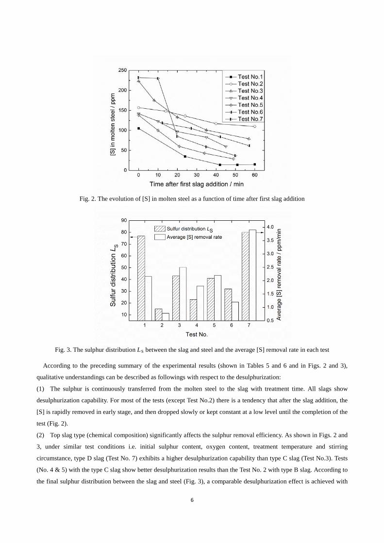
Fig. 2. The evolution of [S] in molten steel as a function of time after first slag addition
Fig. 3. The sulphur distribution LS between the slag and steel and the average [S] removal rate in each test
According to the preceding summary of the experimental results (shown in Tables 5 and 6 and in Figs. 2 and 3),
qualitative understandings can be described as followings with respect to the desulphurization:
(1) The sulphur is continuously transferred from the molten steel to the slag with treatment time. All slags show
desulphurization capability. For most of the tests (except Test No.2) there is a tendency that after the slag addition, the
[S] is rapidly removed in early stage, and then dropped slowly or kept constant at a low level until the completion of the
test (Fig. 2).
(2) Top slag type (chemical composition) significantly affects the sulphur removal efficiency. As shown in Figs. 2 and
3, under similar test conditions i.e. initial sulphur content, oxygen content, treatment temperature and stirring
circumstance, type D slag (Test No. 7) exhibits a higher desulphurization capability than type C slag (Test No.3). Tests
(No. 4 & 5) with the type C slag show better desulphurization results than the Test No. 2 with type B slag. According to
the final sulphur distribution between the slag and steel (Fig. 3), a comparable desulphurization effect is achieved with
7
the type D (Test No. 7) and type A (Test No. 1) slags. However, the average [S] removal rate is lower for the type A slag,
which is due to the lowest initial sulphur content of the steel in the case of Test No. 1.
(3) Besides the influence of the top slag chemistry, the desulphurization behavior is affected with initial sulphur
content and oxygen level of the steel. As expected, sulphur is removed easily from the steel with higher initial sulphur
content as can be seen in Figs.2 & 3 for Test No. 3 (type C slag and 223 ppm initial [S]) and Test No.5 (type C slag and
138 ppm initial [S]). On the other hand, for Test No. 4 and 5, different desulphurization effect for similar initial
conditions (type C slag and initial sulphur content) suggests the influence of the oxygen level. A better desulphurization
is observed in Test No. 5 with aluminum deoxidation than in Test No. 4 without it.
(4) The influence of kinetic condition on the desulphurization is investigated in Test No. 6 with bottom Ar blowing. As
can be seen in Figs 2 and 3, a poor desulphurization is observed in Test No. 6 as compared to the Test No. 5, which has
similar test conditions (i.e. slag type C, 3 grams aluminum deoxidation, around 140 ppm initial [S] and temperature
ranging from 1600 to1650 °C) with the exception of bottom Ar blowing in Test No. 6. According to the visual
observation during the test, bottom Ar blowing pushes the top slag onto the crucible wall, which leads to a large open
eye in the slag/metal bath, reducing slag/metal contact area and therefore weakening the desulphurization kinetics. This
inversely confirms the kinetic effect on the desulphurization reaction. Further work is necessary to improve the present
experimental set-up to precisely control the reaction kinetics.
3.2 Thermodynamic consideration on the desulphurization
Sulphur capacity CS, a function of slag composition and temperature, is defined as a measurement of the sulphur
absorption ability of metallurgical slag by Fincham and Richardson[7],
0(O)
S(S)
expaGC
RT f ∆
= − ⋅ (1)
where (O)a is the activity of oxide ions in the slag; (S)f is the activity coefficient of sulfide ions in the slag; R is the gas
constant, 8.314 J/(mol·K); T is the temperature in K; ο∆G is the Gibbs energy of the following reaction, J/mol:
( )2- 2-2 2
1 1S (g) + O (S ) + O (g)2 2
= 118535 58.8157G Tο∆ = − (2)
by combining the definition of sulphur capacity (i.e. Eq. (1)) and the reaction (2), the sulphur capacity of the slag can be
expressed as follow:
( ) 2
2
12
O
SS
%SP
CP
= ⋅
(3)
where (%S) is the weight percentage of sulphur content in the slag; 2OP and
2SP are partial pressures of O2 and S2 gas
in the system, Pa.
In general, the sulphur capacity can be measured through the classical gas (CO+CO2+SO2+Ar)/liquid slag
equilibrium experiment. There are also several mathematical models[8-10] developed for the sulphur capacity calculation.
In order to better understand the desulphurization results obtained in the tests, the sulphur capacities of the slag systems,
8
which were employed in the present tests, is evaluated with the aid of FactSage software. In the calculation, the
thermodynamic equilibrium between the slag and a gas mixture (CO: CO2: SO2: Ar = 5: 4: 1: 10) at specific
temperature is calculated with the Equilibrium module in the FactSage. On substitution of the equilibrated mole amount
of O2 (g) and S2 (g), as well as the equilibrated sulphur content in slag into Eq. (3), the sulphur capacity can be
estimated. It should be noted that the initial chemistry of the gas mixture would not influence the final result of the
sulphur capacity in the calculation. The database of FACT and FToxid were used in the calculation. The calculated
results at 1873 K for CAS-14.4%CaF2 (CAS represents CaO-Al2O3-SiO2), CAS-2.5%Fe2O3-1%MgO-4%TiO2, CAS
and CAS-2.1%Fe2O3-0.6%MgO-1.7%TiO2 slag systems, which respectively correspond to slag A, B, C and D, are
shown in Fig. 4. The solid points in Figs. 4a, 4b, 4c and 4d represent the initial composition of the slag A, B, C and D,
respectively. The open symbols represent the final composition of the slags after the tests. It should be mentioned that
these data points are not the exact composition of the slag, because the minor compounds are neglected to integrate the
slag into the figure with three principle components, i.e. CaO, SiO2 and Al2O3. The calculated sulphur capacity values
for the initial slag and the final slag from Test No. 1 to 7 are listed in Table 7. The exact composition and the measured
temperature are used in these calculations.
It can be seen from Fig. 4 that the sulphur capacity increases with the increase of %CaO and decreases with the
increase of %SiO2 and %Al2O3 in CA based slag. The melting temperature of CA based slag is high in CaO rich region.
Based on the results of Fig. 4 and Table 7, it can be concluded that (1) slag B has the lowest sulphur capacity while slag
A shows the highest one, which is because of the slag chemistry, mainly due to difference in the CaO content in these
two slags; (2) under same temperature, larger liquid area are observed with CAS-2.5%Fe2O3-1%MgO-4%TiO2 (Fig. 4b)
and CAS-2.1%Fe2O3-0.6%MgO-1.7%TiO2 (Fig. 4d) slag systems as compared to the CAS-14.4%CaF2 (Fig. 4a) and
CAS (Fig. 4c) slag systems. This indicates that minor additions of Fe2O3, MgO and TiO2 to the slag lowers the melting
temperature of the slags, and would facilitate the desulphurization kinetics; (3) slag composition slightly changed after
the treatment and remained on the lime saturated liquidus for the pre-melted synthetic slags (Figs. 4b and 4d), while it
moved toward to the lower sulphur capacity direction for the tests with the slags (Figs. 4a and 4c) consisting of the
mixtures of oxides and calcium fluoride. The later implies that the desulphurization capability of the mixture slags
decreases as reaction proceeds. This is not the case for the pre-melted synthetic slags, suggesting advantages of
chemical and physical homogenization of the slags for the desulphurization; (4) the iso-log CS curves are parallel to the
lime saturated liquidus and the CS value increases with the curves being close to the lime saturated liquidus. This
indicates a necessary optimization of the slags for the desulphurization with respect to its thermodynamic and kinetic
properties, i.e. sulphur capacity and viscosity of the slags. If the kinetics allows, CaO saturated slags are recommended
for the desulphurization refining practice.
9
Fig. 4. Iso-log CS contours of the slags at 1600 ℃, a) CAS-14.4%CaF2, b) CAS-2.5%Fe2O3-1%MgO-4%TiO2, c) CAS and d) CAS-2.1%Fe2O3-0.6%MgO-1.7%TiO2 slag systems
Table 7. The calculated sulphur capacity for the initial slag and the final slag through Test No. 1 to 7 CS T1
Substituting interaction parameters (shown in Table 8), steel composition, oxygen activity of the molten steel,
operation temperature, and calculated sulphur capacity (shown in Table 7), respectively into Eq. (6) and (7), the sulphur
distribution (LS) can be calculated. Fig. 6 shows comparison of the measured and the calculated sulphur distribution
value, which in the upper diagram of Fig. 6 is obtained by using the chemistry of the initial slags and in the lower
diagram by that of the final slags. The results in Fig. 6 demonstrated that (1) relation between the calculated and
measured sulphur distribution follows approximately a straight line, which is parallel to the one by one relationship, i.e.
the dashed lines in Fig. 6, suggesting an reliable assessment for both calculated and measured LS data; (2) the
calculation is more reasonable when using the chemistry of the final slags; (3) the calculated log LS (thermodynamic
equilibrium) value is around one time larger than the measured value. This means that the slag/molten steel interaction
was far from equilibrium with respect to the desulphurization reaction in the present tests. Therefore, desulphurization
capabilities of the top slags have not been fully utilized in the present pilot ladle treatment. If the kinetics allows, the
desulphurization effect can certainly be improved by using the current top slags. In the following section, the
desulphurization kinetics is discussed with respect to the experimental conditions.
Fig. 6. Comparison between the measured and calculated sulphur distribution LS in logarithmic scale
3.3 Desulphurization kinetics
Mathematical model
To better understand the desulphurization behavior in the pilot experiments, a kinetic model is developed to predict
sulphur evolution in the molten steel during the tests. The model is based on the two film theory that the dissolved
sulphur is removed by permanent contact reaction at the interface between molten steel and slag. A schematic
12
representation of the desulphurization kinetics is illustrated in Fig. 7, where C[i], C(i), i[ ]C i and i
( )C i , respectively
represent the concentration of species i in molten steel, in slag, at the interface towards molten steel and at the interface
towards slag. According to Fig. 7, the desulphurization process can be divided into the following kinetic steps:
(1) [S] is transferred from molten steel towards the slag, meanwhile the (O) is transferred from the slag towards the
steel bath.
(2) [S] and (O) are exchanged at the slag/steel interface through the desulphurization reaction, i.e. Eq. (4).
(3) [O] and (S) are transferred from the slag/steel interface towards steel and slag phase, respectively.
To simplify the mathematical model and calculation, the following assumptions were made: (a) there is no species
(i.e. reactants and products) accumulated at the interface; (b) slag is uniformly covered on the surface of molten steel; (c)
the dissolved elements, such as sulphur and oxygen, are homogeneously distributed in the steel phase at the beginning
of the experiments; (d) chemical reaction at the interface is fast enough for not being the rate-limiting step of the
desulphurization; (e) chemical ractions at the interface reached equilibrium.
Fig. 7. A schematic representative of the desulphurization kinetics
In general, possible rate controlling steps of the desulphurization are considered to be the mass transport aspects, such
as transfer of [S] from molten steel towards the reaction interface, (S) from the interface towards bulk slag phase,
(O) from slag towards the interface and [O] from the interface towards molten steel. According to the previous studies[2,
4, 17], transfer of (S) from the interface to bulk slag is substantiated to be the rate controlling step of the desulphurization
reaction. Therefore, desulphurization rate can be expressed in terms of the flux of (S) in slag phase, which is written as
Eq. (8):
i im [S] [S] s (S) (S)= (C C ) (C -C )J k k− = (8)
where J is the sulphur flux in slag phase, mol/(m2·s); km and ks are the mass transfer coefficient of sulphur, respectively,
in steel and slag phase at the permanent contact reaction zone, m/s. Thus, sulphur removal rate in molten steel can be
calculated as follow:
13
}{si
[S] ( ) (S)t ts
m s
W A kd Sdt W V
⋅ ⋅− = −
⋅ (9)
in which
i S(S) [S]t tL= (10)
where A is contact area between the slag and steel, m2; Vs is the volume of slag at time t, m3; Wm and Ws are the weight
of molten steel and slag at time t, kg, respectively; i(S)t , (S)t and [S]t are the sulphur content at the interface, in slag,
and in steel at time t, ppm, respectively. Thanking the mass balance of sulphur between the steel and the slag into
account, (S) in slag at time t can be expressed by Eq. (11),
([S] [S] )(S)
o tt m
s
WW
−=
(11)
where [S]o is the sulphur content in the steel at time = 0 s, ppm. Combining the Eqs. (9) to (11), following equation is
derived:
{ }S S Sln ( )[S] [S] ( ) ln [S]tm m s s m
ms s s
W W A k WL L t L
WW W Wρ ⋅ ⋅
+ − ° = − + + ⋅ °
(12)
where sρ is the density of slag at experiment temperature, kg/cm3. Furthermore, the mass transfer coefficient ks can be
calculated by using the empirical equation (13) [4, 17, 18]:
s SQk DA
β= (13)
273aQ TP
QP
ο
= (14)
where β is empirical coefficient, 1 m-1/2; SD is the sulphur diffusivity in the slag, m2/s; Qο is total gas flow rate,
m3/s; Pa is the standard atmospheric pressure and P is the gas pressure in the furnace, Pa.
The diffusivity of sulphur in CAS based slag is estimated by using the model developed by Muhmood et al. [6],
1166.5log( ) 8.7063SDT
= − − (15)
The density of CAS slag sρ is estimated by using the model developed by Persson[19],
(1 )T
i iis
mi mii
X MHX V
R
ρλ
=+
∑∑
(16)
where miV is molar volume for the pure substance of i, cm3/mol; ρ i is the density of pure substance of i at experimental
temperature, g/cm3; mH is the relative integral molar enthalpy, J/mol; iX and iM are the mole fraction and
molecular mass of i component, respectively and λ is a constant, 0.06.
The miV can be calculated by empirical equation developed by Muhmood[20],
imi
i
MV
ρ= (17)
14
2 3
33.04 1.15 10 (T 2303)Al Oρ −= − × − (18)
2
43.0451 4 10 TSiOρ −= − × (19)
43.4151 2 10 TCaOρ −= − × (20)
Substituting experimental parameters estimated through Eqs. (13) to (20) into Eq. (12), evolution of sulphur content
in the molten steel during the ladle refining can be calculated.
Calculated results
The experimental parameters used in the calculations are summarized in Table 9. The prediction of [S] evolution as a
function of time is calculated for Test No. 3 to 6. In the calculation, the value of 4.7×10⁻¹⁰ m2/s is used for sulphur
diffusivity calculation[6]. The gas flow rate of 0.5 L/min, the furnace pressure of 5 Bar and the temperature at end of the
test are used for the calculation of mass transfer coefficient of sulphur in the slag phase (ks). Since the slag covered only
around 1/4 molten steel surface (as shown in Fig. 8) during the test, the steel/slag contact area was considered to be 1/4
of the cross section area of the crucible in the calculation. For comparison, both the experimental and calculated results
are plotted in Fig. 9.
Table 9. The experimental parameters used in the calculations
Test No. LS T
(℃)
ρ
(g/cm3)
DS
(m2/s)
A
(m2)
k
(m/s)
[S]°
(ppm)
3 445 1612 2.79 4.7×10⁻¹⁰ 4.4×10⁻³ 1.15×10⁻⁶ 223
4 430 1590 2.80 4.7×10⁻¹⁰ 4.4×10⁻³ 1.15×10⁻⁶ 142
5 407 1659 2.78 4.9×10⁻¹⁰ 4.4×10⁻³ 1.15×10⁻⁶ 138
6 423 1635 2.79 4.8×10⁻¹⁰ 4.4×10⁻³ 1.15×10⁻⁶ 119
Fig. 8. The situation of the sleel/slag contact during the tests: (a) picture of the slag and steel in the crucible during experiment; (b) schematic diagram of the steel/slag contact
15
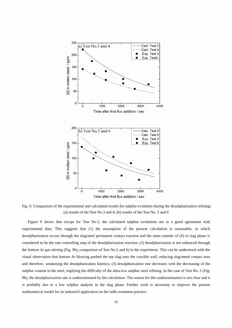
Fig .9. Comparison of the experimental and calculated results for sulphur evolution during the desulphurization refining:
(a) results of the Test No.3 and 4; (b) results of the Test No. 5 and 6
Figure 9 shows that except for Test No.5, the calculated sulphur evolutions are in a good agreement with
experimental data. This suggests that (1) the assumption of the present calculation is reasonable, in which
desulphurization occurs through the slag/steel permanent contact reaction and the mass transfer of (S) in slag phase is
considered to be the rate controlling step of the desulphurization reaction; (2) desulphurization is not enhanced through
the bottom Ar gas stirring (Fig. 9b), comparison of Test No.5 and 6) in the experiment. This can be understood with the
visual observation that bottom Ar blowing pushed the top slag onto the crucible wall, reducing slag/metal contact area
and therefore, weakening the desulphurization kinetics; (3) desulphurization rate decreases with the decreasing of the
sulphur content in the steel, implying the difficulty of the ultra-low sulphur steel refining. In the case of Test No. 5 (Fig.
9b), the desulphurization rate is underestimated by the calculation. The reason for this underestimation is not clear and it
is probably due to a low sulphur analysis in the slag phase. Further work is necessary to improve the present
mathematical model for its industrial application on the ladle treatment practice.
16
4. Conclusion
The desulphurization of austenitic stainless steel by using the lime-alumina based slags has been studied. The sulphur
capacity was calculated based on the experimental data with the aid of FactSage software. The effect of sulphur
capacity and experimental conditions on the desulphurization was investigated based on the thermodynamic
consideration. A desulphurization kinetic model was developed for the prediction of sulphur evolution in the steel
during the ladle treatment. The main results can be summarized as follow:
(1) The iso-sulphur capacity curves at 1600 °C were calculated with respect to the CaO-Al2O3 based slag and
CaO-CaF2 based systems. The iso-log CS curves are parallel to the lime saturated liquidus and the CS value increases
with the curves being close to the lime saturated liquidus. If the kinetics allows, CaO saturated slags are recommended
for the desulphurization refining practice.
(2) Experimental results showed that slag and steel chemistry, temperature, bottom Ar blowing had complex
influences on the desulphurization, which is, however, mainly determined by the sulphur capacity of the slags. A
comparable desulphurization effect was obtained with an optimized lime-alumina based slag as with the lime-fluorspar
based slags.
(3) A kinetic model based on the slag/steel permanent contact reaction was established for the desulphurization. The
calculated sulphur evolutions in the steel during the pilot tests were in a good agreement with experimental data,
suggesting a promising industrial application of the model on the ladle treatment practice.
References
[1] Hino, M. and S. Ban-ya, Equilibria of Sulphur and Oxygen Between CaO-Al2O3 Based Slags and Liquid Iron. Ultra High Purity Base Metal, ed. K. Abiko, K. Hirokawa, and S. Takaki. 1995, Sendai, Japan: The Japan Institute of Metals.
[2] Chushao, X. and T. Xin, Kinetics of desulfurization of hot metal by CaO-CaF2 based fluxes. ISIJ international, 1992. 32(10): p. 1081-1083.
[3] Iwamasa, P. and R. Fruehan, Effect of FeO in the slag and silicon in the metal on the desulfurization of hot metal. Metallurgical and Materials Transactions B, 1997. 28(1): p. 47-57.
[4] Seshadri, V. and C. da Silva, A kinetic model applied to the molten pig iron desulfurization by injection of lime-based powders. ISIJ International, 1997. 37(1): p. 21-30.
[5] M.A.T. Andersson, P.G.J., and M.Hallberg, Optimisation of ladle slag composition by application of sulphide capacity model. Ironmaking & Steelmaking, 2000. 27: p. 286-293.
[6] Muhmood, L., et al., Evaluating the Diffusion Coefficient of Sulfur in Low-Silica CaO-SiO2-Al2O3 Slag. Metallurgical and Materials Transactions B. 42(2): p. 274-280.
[7] Fincham, C. and F. Richardson, The behaviour of sulphur in silicate and aluminate melts. Proceedings of the Royal Society of London. Series A. Mathematical and Physical Sciences, 1954. 223(1152): p. 40.
[8] Sosinsky, D.J. and I. Sommerville, The composition and temperature dependence of the sulfide capacity of metallurgical slags. Metallurgical and Materials Transactions B, 1986. 17(2): p. 331-337.
[9] Nzotta, M., D. Sichen, and S. Seetharaman, A study of the sulfide capacities of iron-oxide containing slags. Metallurgical and Materials Transactions B, 1999. 30(5): p. 909-920.
17
[10] Young, R., et al., Use of optical basicity concept for determining phosphorus and sulphur slag- metal partitions. Ironmaking & Steelmaking, 1992. 19(3): p. 201-219.
[11] Chan, A.H. and R. Fruehan, The sulfur partition ratio and the sulfide capacity of Na2O-SiO2 slags at 1200 ℃. Metallurgical and Materials Transactions B, 1986. 17(3): p. 491-496.
[12] Wagner, C., S. Mellgren, and J.H. Westbrook, Thermodynamics of alloys. Vol. 4. 1952: Addison-Wesley Press. [13] Suzuki, K., S. Ban-Ya, and M. Hino, Deoxidation equilibrium of Cr-Ni stainless steel with Si at the temperatures
from 1 823 to 1 923 K. ISIJ international, 2002. 42(2): p. 146-149. [14] Suzuki, K., S. Ban-Ya, and M. Hino, Deoxidation equilibrium of chromium stainless steel with Si at the
temperatures from 1 823 to 1 923 K. ISIJ international, 2001. 41(8): p. 813-817. [15] Deo, B. and R. Boom, Fundamentals of steelmaking metallurgy. 1993: Prentice Hall International. [16] Miki, T. and M. Hino, Numerical Analysis on Si Deoxidation of Molten Fe, Ni, Fe-Ni, Fe-Cr, Fe-Cr-Ni, Ni-Cu and
Ni-Co Alloys by Quadratic Formalism. ISIJ international, 2005. 45(12): p. 1848-1855. [17] Roy, G., et al., Dephosphorization of ferromanganese using BaCO3 based fluxes by submerged injection of
powders: A preliminary kinetic study. Metallurgical and Materials Transactions B, 2001. 32(3): p. 558-561. [18] Riboud, P. and R. Vasse, Désulfuration de l'acier en poche: synthèse des résultats théoriques et industriels. CIT de la
Revue de Metallurgie, 1985. 82(11): p. 801-810. [19] Persson, M., J. Zhang, and S. Seetharaman, A Thermodynamic Approach to a Density Model for Oxide Melts. Steel
Rresarch International, 2007. 78(4): p. 290. [20] Muhmood, L. and S. Seetharaman, Density Measurements of Low Silica CaO-SiO2-Al2O3 Slags. Metallurgical
and Materials Transactions B. 2010. 41(4): p. 833-840.