Page 1
10/4/13 TMMS DDS 1
Department of Computer Science and Engineering
The University of Texas at Arlington
Detailed Design Specification TMMS
Team: TK Force
Team Members:
Richard Sherrill
David Odhiambo
Huadong Feng
Robert Castillo
Page 2
10/4/13 TMMS DDS 2
Table of Contents
1 Introduction ............................................................................................................................. 8
1.1 Document Overview ........................................................................................................ 8
1.2 Product Overview ............................................................................................................. 8
1.3 Project Scope .................................................................................................................... 8
2 Architecture Overview ............................................................................................................ 9
2.1 Input layer ...................................................................................................................... 10
2.2 Data Controller layer ...................................................................................................... 11
2.3 Database layer: ............................................................................................................... 11
2.4 Match Event Processor: .................................................................................................. 11
2.5 Presentation layer: .......................................................................................................... 11
3 Input Layer ............................................................................................................................ 12
3.1 Description ..................................................................................................................... 12
3.2 Admin Input: Keyboard/Mouse Input ............................................................................ 12
3.3 Equipment Input: Filter .................................................................................................. 13
3.4 Equipment Input: Equipment Input ................................................................................ 14
3.5 Admin Package .............................................................................................................. 14
3.6 Force Data Package ........................................................................................................ 15
4 Data Controller Layer ........................................................................................................... 17
4.1 Description ..................................................................................................................... 18
4.2 Input Controller: Object Identifier module .................................................................... 18
4.3 Database Controller: DB Store ....................................................................................... 19
4.4 Database Controller: Log Creator .................................................................................. 20
4.5 Database Controller: Request Log ................................................................................. 21
4.6 Match Event Controller: Timestamp .............................................................................. 22
4.7 Match Event Controller: Time Module .......................................................................... 23
Page 3
10/4/13 TMMS DDS 3
4.8 Match Event Controller: Match Log .............................................................................. 24
4.9 Game Output Controller: Game Output Creator ............................................................ 25
5 Database Layer...................................................................................................................... 27
5.1 Description ..................................................................................................................... 27
5.2 Database Manager: Store Contestant ............................................................................. 27
5.3 Database Manager: Store Log ........................................................................................ 28
5.4 Database Manager: Retrieve Match Log ........................................................................ 29
6 Match Event Processor Layer ............................................................................................... 31
6.1 Description ..................................................................................................................... 31
6.2 Match Event Processor: Admin Match Data .................................................................. 31
6.3 Match Event Processor: Force Data ............................................................................... 32
6.4 Match Event Processor: Match Event ............................................................................ 33
6.5 Calibration: Determine Adjustment Factor .................................................................... 34
6.6 Force Calculations: Score Modifiers .............................................................................. 35
7 Presentation Layer ................................................................................................................ 37
7.1 Description ..................................................................................................................... 37
7.2 Output Handler: Determine Display Command ............................................................. 37
7.3 Admin Display: Update Admin Display ........................................................................ 38
7.4 Audience Display: Update Audience Display ................................................................ 39
8 Quality Assurance ................................................................................................................. 41
8.1 Test Plan and Procedures ............................................................................................... 41
8.2 Module/Unit Test ........................................................................................................... 41
8.3 Component Testing ........................................................................................................ 45
8.4 Integration Testing ......................................................................................................... 46
8.5 System Verification Testing ........................................................................................... 46
8.6 Test Cases ....................................................................................................................... 46
9 Requirements Mapping ......................................................................................................... 48
9.1 Purpose ........................................................................................................................... 48
9.2 Layer Requirements Traceability ................................................................................... 48
9.3 Module Requirements Traceability ................................................................................ 50
10 Acceptance Plan .................................................................................................................... 52
Page 4
10/4/13 TMMS DDS 4
10.1 Overview .................................................................................................................... 52
10.2 Packaging and Installation .......................................................................................... 52
10.3 Acceptance Testing ..................................................................................................... 52
10.4 Acceptance Criteria .................................................................................................... 53
11 Hardware Components.......................................................................................................... 58
11.1 Overview .................................................................................................................... 58
11.2 EPRO 2910 Daedo E-Hogu w/out transmitter ........................................................... 58
11.3 EPRO 2913 Daedo E-Headgear w/out transmitter ..................................................... 59
11.4 EPRO 2903 Daedo E-Footgear................................................................................... 60
11.5 EPRO 2909 Daedo E-Hogu & E-Headgear Wireless Transmitter ............................. 61
11.6 EPRO 2906 Daedo USB Wireless Receiver ............................................................... 62
Page 5
10/4/13 TMMS DDS 5
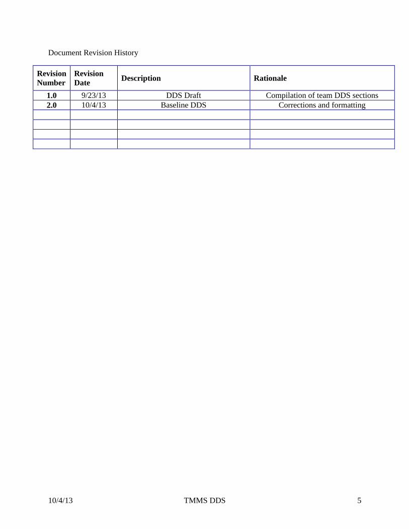
Document Revision History
Revision
Number
Revision
Date Description Rationale
1.0 9/23/13 DDS Draft Compilation of team DDS sections
2.0 10/4/13 Baseline DDS Corrections and formatting
Page 6
10/4/13 TMMS DDS 6
List of Tables
Table 3-1: Input Layer Data Flows ............................................................................................... 12
Table 4-1: Data Controller Data Flows ......................................................................................... 17
Table 5-1: Database Data Flows ................................................................................................... 27
Table 6-1: Match Event Processor Data Flows............................................................................. 31
Table 7-1: Presentation Data Flows .............................................................................................. 37
Table 8-1: Test Cases .................................................................................................................... 46
Table 9-1: Customer Requirements Mapping ............................................................................... 48
Table 9-2: Performance Requirements Mapping .......................................................................... 49
Table 9-3: Other Requirements Mapping ..................................................................................... 49
Table 9-4: Customer Requirements Mapping ............................................................................... 50
Table 9-5: Performance and Other Requirements Mapping ......................................................... 51
Table 10-1: Audience Screen Verification ................................................................................... 53
Table 10-2: Real Time Verification .............................................................................................. 54
Table 10-3: Save Log Data Verification ....................................................................................... 55
Table 10-4: User Friendliness Verification ................................................................................... 55
Table 10-5: Force Accuracy Verification ..................................................................................... 57
Page 7
10/4/13 TMMS DDS 7
List of Figures
Figure 2-1: Architecture Layout Diagram ...................................................................................... 9
Figure 2-2: Detail Design Layout Diagram .................................................................................. 10
Figure 3-1: Input Layer Module Diagram .................................................................................... 12
Figure 4-1: Data Controller Layer Module Diagram .................................................................... 17
Figure 5-1: Database Layer Module Diagram .............................................................................. 27
Figure 6-1: Match Event Processor Layer Module Diagram ........................................................ 31
Figure 7-1: Presentation Layer Module Diagram ......................................................................... 37
Figure 11-1: EPRO 2910 Daedo E-Hogu w/out transmitter ......................................................... 58
Figure 11-2:EPRO 2913 Daedo E-Headgear w/out transmitter ................................................... 59
Figure 11-3: EPRO 2903 Daedo E-Footgear ................................................................................ 60
Figure 11-4: EPRO 2909 Daedo E-Hogu & E-Headgear Wireless Transmitter .......................... 61
Figure 11-5:EPRO 2906 Daedo USB Wireless Receiver ............................................................. 62
Page 8
10/4/13 TMMS DDS 8
1 Introduction
1.1 Document Overview
The Detail Design Specification (DDS) is intended to provide a detailed breakdown of the
individual modules in each subsystem defined in the Architecture Design Specification (ADS).
Also, this document will provide data flow definitions between the modules, requirements
traceability matrix, and testing considerations for the system.
1.2 Product Overview
The Taekwondo Match Management System (TMMS) will be used to manage a match between
two players competing in a Taekwondo competition and display parts of this information to an
audience. The TMMS will allow administrators to input competitor information and store it in an
internal database as well as display this information back to the administrator and an audience.
The TMMS will be started from a computer and will communicate with Daedo equipment that
two competitors wear for protection. The Daedo equipment is outside of our system, but captures
the force of hits and relays that information to the TMMS. The TMMS then uses this information
to apply force deductions to a life bar which is displayed to the administrators and an audience.
The TMMS also uses the force information to test the equipment using a test mode built into the
TMMS which displays the amount of force to the administrators. The system will also allow
administrators to apply penalties, set score modifier deductions, start medical timeouts for the
system, and pull up match event information for an active competition.
1.3 Project Scope
The TMMS is a software management system that will receive data from Daedo equipment worn
by two competitors engaging in a Taekwondo match. The system is a pure software system and
has no external parts that make up the system, but must receive data from Daedo equipment in
order to execute all of its functions. The main functions of the system are keeping life bars of
two competitors based off of force deductions and ensuring that the system can keep track of
both competitors in a reliable manner.
Page 9
10/4/13 TMMS DDS 9
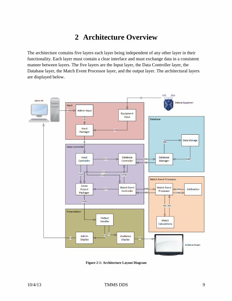
2 Architecture Overview
The architecture contains five layers each layer being independent of any other layer in their
functionality. Each layer must contain a clear interface and must exchange data in a consistent
manner between layers. The five layers are the Input layer, the Data Controller layer, the
Database layer, the Match Event Processor layer, and the output layer. The architectural layers
are displayed below.
Figure 2-1: Architecture Layout Diagram
Page 10
10/4/13 TMMS DDS 10
Figure 2-2: Detail Design Layout Diagram
2.1 Input layer
The Input layer will receive input from an administrator’s screen and the Daedo
equipment. The administrator’s screen will enter data such as competitor information,
setup of the system, and altering the system. The Daedo equipment will send raw data
that represents the force of impact on each competitor’s equipment and the TMMS will
receive this data. This layer will then determine the type of data it received and package
the data for transfer to the Data Controller layer. The packaged data is data that is
relevant to the next layer.
Page 11
10/4/13 TMMS DDS 11
2.2 Data Controller layer
The Data Controller layer will be responsible for routing packaged data received from the
administrator’s screen, from the Daedo equipment, and any received data from the
database to its correct destination. The Data Controller layer is also responsible for
holding data that has been received from the Input layer or the database, and packaging
information received from the Database layer or the Match Event Processor layer. The
Data Controller layer will then make sure that all the relevant information is packaged
together to send to the output layer.
2.3 Database layer:
The Database layer will be responsible for receiving input from the database handler. The
database manager inside the Database layer will then decide if this information needs to
be stored or information needs to be retrieved based off of the data that has been sent to it
from the database handler. The database manager will then create these queries, execute
the queries, receive the result of the queries, and then package and send the data back to
the Input layer.
2.4 Match Event Processor:
The match event processor will be responsible for changing the state of a match. Any raw
force data that has been received from the Daedo equipment will pass through this layer
in order to be converted to force data that can be read by the game output packager in the
Data Controller layer. This layer will also add any score modifiers to that force data in
order to correctly represent the state of each competitors life bar.
2.5 Presentation layer:
The Presentation layer will be responsible for correctly displaying the data that has come
from the Data Controller layer. This data will be force deductions to the life bar,
administration input data such as information about a competitor, and different modes of
the TMMS such as test mode. The Presentation layer will also be responsible for making
sure that the appropriate information is sent to the administrator screen and audience
screen.
Page 12
10/4/13 TMMS DDS 12
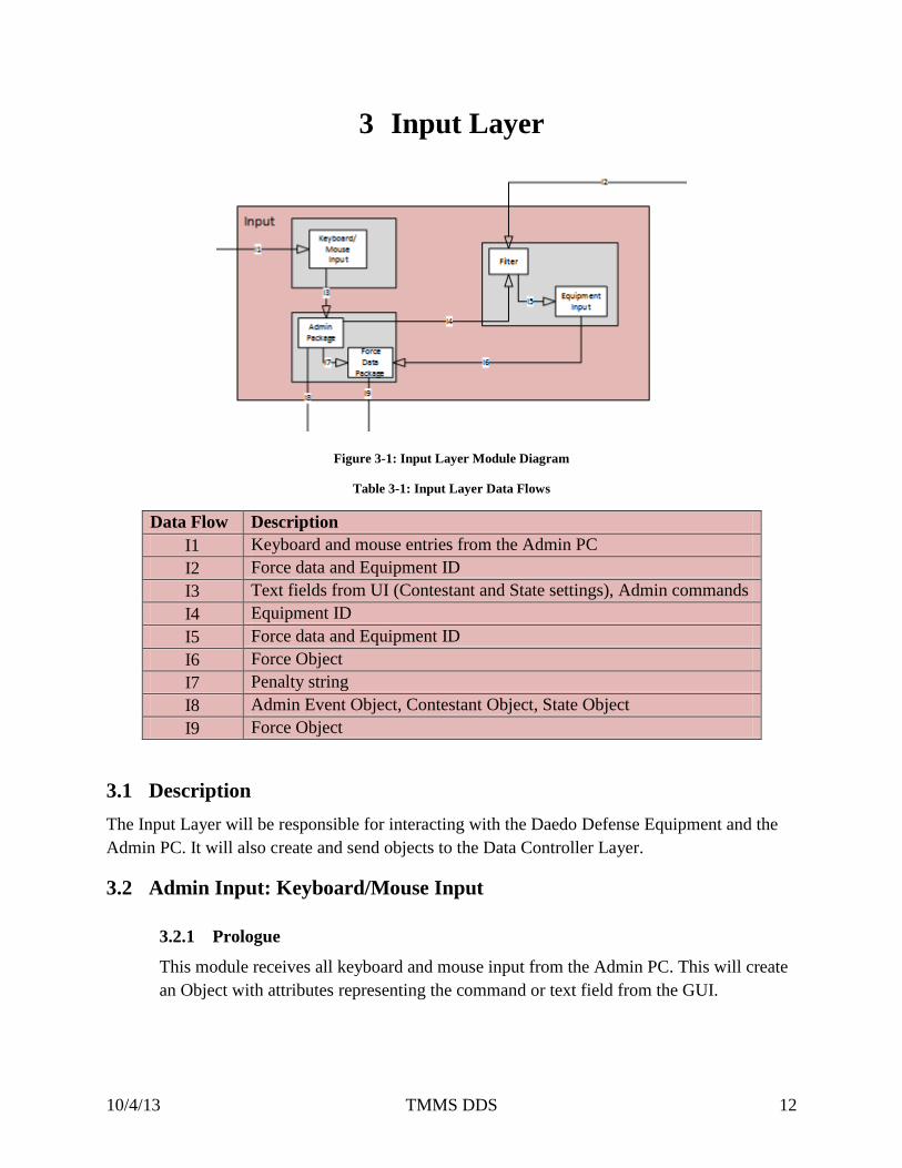
3 Input Layer
Figure 3-1: Input Layer Module Diagram
Table 3-1: Input Layer Data Flows
Data Flow Description
I1 Keyboard and mouse entries from the Admin PC
I2 Force data and Equipment ID
I3 Text fields from UI (Contestant and State settings), Admin commands
I4 Equipment ID
I5 Force data and Equipment ID
I6 Force Object
I7 Penalty string
I8 Admin Event Object, Contestant Object, State Object
I9 Force Object
3.1 Description
The Input Layer will be responsible for interacting with the Daedo Defense Equipment and the
Admin PC. It will also create and send objects to the Data Controller Layer.
3.2 Admin Input: Keyboard/Mouse Input
3.2.1 Prologue
This module receives all keyboard and mouse input from the Admin PC. This will create
an Object with attributes representing the command or text field from the GUI.
Page 13
10/4/13 TMMS DDS 13
3.2.2 Interfaces
Source Module Destination Module Description
Admin PC (physical device) Keyboard/Mouse Input
(Admin Input subsystem)
Keyboard and Mouse events
with commands or text objects
Keyboard/Mouse Input
(Admin Input subsystem)
Admin Package (Input
Packager subsystem)
Text objects or Admin
command
3.2.3 External Data Dependencies
This module requires a keyboard and mouse attached to the Admin PC.
3.2.4 Internal Data Descriptors
This module will send text objects or a command to the next module.
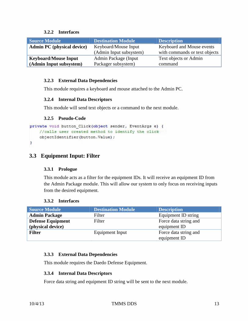
3.2.5 Pseudo-Code
3.3 Equipment Input: Filter
3.3.1 Prologue
This module acts as a filter for the equipment IDs. It will receive an equipment ID from
the Admin Package module. This will allow our system to only focus on receiving inputs
from the desired equipment.
3.3.2 Interfaces
Source Module Destination Module Description
Admin Package Filter Equipment ID string
Defense Equipment
(physical device)
Filter Force data string and
equipment ID
Filter Equipment Input Force data string and
equipment ID
3.3.3 External Data Dependencies
This module requires the Daedo Defense Equipment.
3.3.4 Internal Data Descriptors
Force data string and equipment ID string will be sent to the next module.
Page 14
10/4/13 TMMS DDS 14
3.3.5 Pseudo-Code
3.4 Equipment Input: Equipment Input
3.4.1 Prologue
This module will receive the equipment ID and force data from the Filter module and
create a Force Data Object.
3.4.2 Interfaces
Source Module Destination Module Description
Filter Equipment Input Sends Equipment Object
Equipment Input Force Data Packager Sends Equipment Object
3.4.3 External Data Dependencies
This module requires an Equipment Object that contains the equipment ID and type.
3.4.4 Internal Data Descriptors
This module will send an Equipment Object to the next layer
3.4.5 Pseudo-Code
3.5 Admin Package
3.5.1 Prologue
This module will receive text data and admin commands that will be used to create an
Admin Event object (which will contain the Match State Object), send equipment IDs,
and send a penalty command to the Force Data Package.
Page 15
10/4/13 TMMS DDS 15
3.5.2 Interfaces
Source Module Destination Module Description
Keyboard/Mouse Input Admin Package Text data and admin
commands
Admin Package Force Data Package Penalty type as a string
Admin Package Filter Equipment Object
Admin Package Object Identifier Admin Event Object, State
Object, Contestant Object
3.5.3 External Data Dependencies
Text data object.
3.5.4 Internal Data Descriptors
Admin Event Object, State Object, and Contestant Object
3.5.5 Pseudo-Code
3.6 Force Data Package
3.6.1 Prologue
This module creates a Force Data Object from the Equipment Input module data, and the
Admin Event Object (if applicable).
3.6.2 Interfaces
Source Module Destination Module Description
Admin Package Force Data Package Penalty type as a string
Equipment Input Force Data Package Equipment Object
Force Data Package Object Identifier Force Data Object
3.6.3 External Data Dependencies
Penalty string and Equipment Object.
3.6.4 Internal Data Descriptors
Force Data Object that contains the force of a strike, the equipment ID, and the Penalty
enumerated type.
Page 16
10/4/13 TMMS DDS 16
3.6.5 Pseudo-Code
Page 17
10/4/13 TMMS DDS 17
4 Data Controller Layer
Figure 4-1: Data Controller Layer Module Diagram
Table 4-1: Data Controller Data Flows
Data Flow Description
DC1 Contestant object containing contestants first and last name and equipment ID
DC2 Match Event object containing all the events that occurred during the match
DC3 State object containing all information for setting up a match
DC4
DC5 Force object containing integer force data and equipment IDs
DC6 Force object containing integer force data and equipment IDs
DC7 Timestamp as a string which represents the current time
DC8 Stack object containing Match Event objects
DC9 Timestamp to be displayed in the presentations log
DC10 Match Event to be displayed in the presentations log form
DC11 Contestant Object containing contestants first and last name and equipment ID
DC12 Game Output object containing data that must be updated in the Presentation
layer
DC13 Admin Event object containing commands that will start new forms
DC14 Admin Event object containing a request for the match log with the match ID
DC15 Match ID as an integer to be retrieved from the database
DC16 Contestant object containing contestants first and last name and equipment ID
DC17 Match Log object containing all of the match events that occurred during a
specific match
DC18 Time object containing the updated time to be displayed in the presentation
layer
Page 18
10/4/13 TMMS DDS 18
DC19 Timestamp as a string representing the current time
DC20 Request for a timestamp
4.1 Description
The Data Controller Layer controls the flow of data and routes it to the proper subsystem.
4.2 Input Controller: Object Identifier module
4.2.1 Prologue
This module will take in a Contestant object, State object, Admin event object, and a
Force object it will then determine what kind of object it has and send that object to the
appropriate module for further processing.
4.2.2 Interfaces
Object Identifier Interfaces
Source Module Destination Module Description
Admin Package (Input
Packager Subsystem)
Object Identifier (Input
Controller Subsystem)
Contestant object containing
names, and country
Admin Package (Input
Packager Subsystem)
Object Identifier (Input
Controller Subsystem)
State object containing all
information for setting up a
match.
Admin Package (Input
Packager Subsystem)
Object Identifier (Input
Controller Subsystem)
Admin Event object
containing a command for
altering the GUI.
Force Data Package (Input
Packager Subsystem)
Object Identifier (Input
Controller Subsystem)
Force object containing the
amount of force and the
equipment ID that force was
applied to
Object Identifier (Input
Controller Subsystem)
Db Connector (Database
Controller Subsystem)
Contestant and Admin Event
objects
Object Identifier (Input
Controller Subsystem)
Time Controls (Match Event
Processor Subsystem)
State, Force, Admin Event
objects
Object Identifier (Input
Controller Subsystem)
Game Output Creator (Game
Output Controller)
Contestant and Admin Event
objects
4.2.3 External Data Dependencies:
Contestant, State, Admin Event, and Force objects
Page 19
10/4/13 TMMS DDS 19
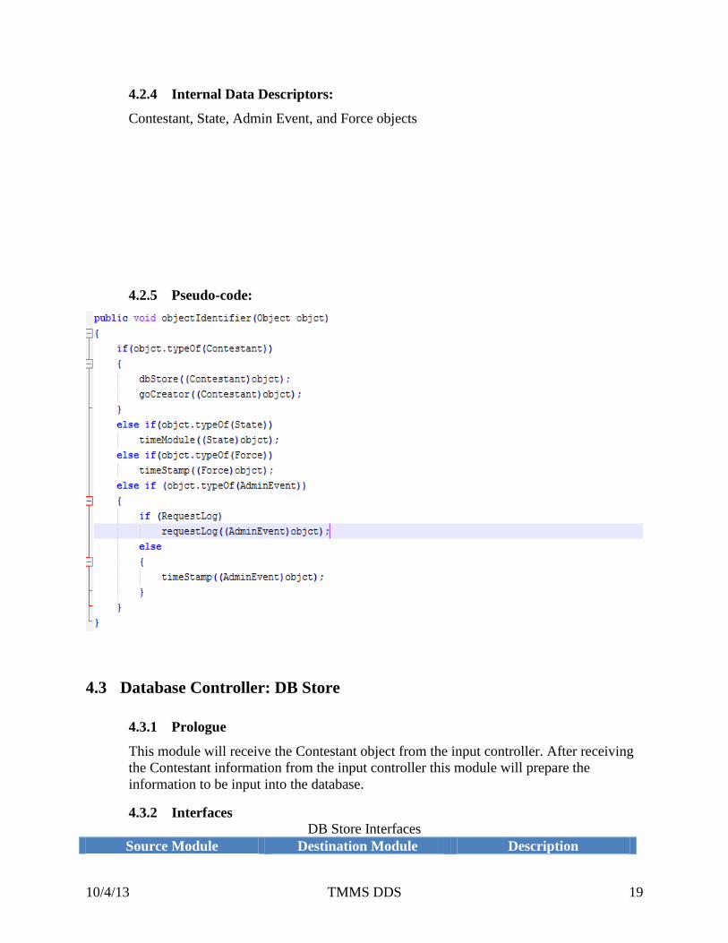
4.2.4 Internal Data Descriptors:
Contestant, State, Admin Event, and Force objects
4.2.5 Pseudo-code:
4.3 Database Controller: DB Store
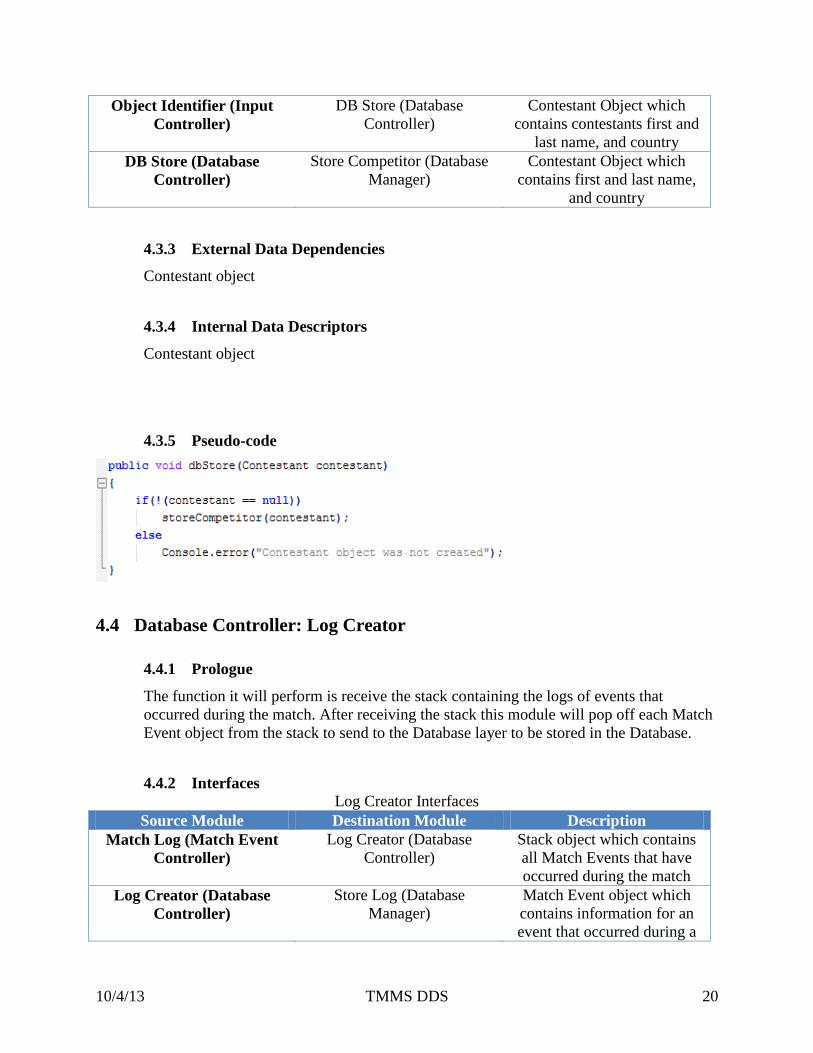
4.3.1 Prologue
This module will receive the Contestant object from the input controller. After receiving
the Contestant information from the input controller this module will prepare the
information to be input into the database.
4.3.2 Interfaces
DB Store Interfaces
Source Module Destination Module Description
Page 20
10/4/13 TMMS DDS 20
Object Identifier (Input
Controller)
DB Store (Database
Controller)
Contestant Object which
contains contestants first and
last name, and country
DB Store (Database
Controller)
Store Competitor (Database
Manager)
Contestant Object which
contains first and last name,
and country
4.3.3 External Data Dependencies
Contestant object
4.3.4 Internal Data Descriptors
Contestant object
4.3.5 Pseudo-code
4.4 Database Controller: Log Creator
4.4.1 Prologue
The function it will perform is receive the stack containing the logs of events that
occurred during the match. After receiving the stack this module will pop off each Match
Event object from the stack to send to the Database layer to be stored in the Database.
4.4.2 Interfaces
Log Creator Interfaces
Source Module Destination Module Description
Match Log (Match Event
Controller)
Log Creator (Database
Controller)
Stack object which contains
all Match Events that have
occurred during the match
Log Creator (Database
Controller)
Store Log (Database
Manager)
Match Event object which
contains information for an
event that occurred during a
Page 21
10/4/13 TMMS DDS 21
match.
4.4.3 External Data Dependencies
Stack of Match Event objects
4.4.4 Internal Data Descriptors
Match Events
4.4.5 Pseudo-code
4.5 Database Controller: Request Log
4.5.1 Prologue
The function this module will perform is to make a request to the database layer that will
retrieve the match log for a specified match and then send this information to the
GoCreator.
4.5.2 Interfaces
Request Log Interfaces
Source Module Destination Module Description
Object Identifier (Input
Controller)
Request Log (Database
Controller)
A match ID that specifies the
match log to get from the
database
Request Log (Database
Controller)
Retrieve Match Log
(Database Manager)
A match ID that specifies the
match log to get from the
database
Retrieve Match Log
(Database Manager)
Request Log (Database
Controller)
Logged data from previous
matches, received from the
database
Request Log (Database
Controller)
Game Output Creator (Game
Output Controller)
Logged information for a
match
Page 22
10/4/13 TMMS DDS 22
4.5.3 External Data Dependencies
Match ID
4.5.4 Internal Data Descriptors
Match ID
4.5.5 Pseudo-code
4.6 Match Event Controller: Timestamp
4.6.1 Prologue:
This module will get a timestamp from the timer and place a timestamp on each event
that must be stored in the database.
4.6.2 Interfaces
Timestamp Interfaces
Source Module Destination Module Description
Object Identifier (Database
Controller)
Timestamp (Match Event
Controller)
Force object which will
contain value of force and
equipment IDs
Object Identifier (Database
Controller)
Timestamp (Match Event
Controller)
Admin commands which can
contain admin stops and starts
Timestamp (Match Event
Controller)
Admin Match Data (Match
Event Processor)
Match State object for setting
a match
Timestamp (Match Event
Controller)
Time Module (Match Event
Processor)
Request time from round
clock
Time Module (Match Event
Controller)
Timestamp (Match Event
Controller)
String value of the current
time
Page 23
10/4/13 TMMS DDS 23
4.6.3 External Data Dependencies
Force object, Admin commands, and string value of time
4.6.4 Internal Data Descriptors
String timestamps
4.6.5 Pseudo-code
4.7 Match Event Controller: Time Module
4.7.1 Prologue
This module will create a new timer for each request from the Admin such as the round
clock, medical clock, and break clock. This module will also create a new thread in order
to update the clock.
4.7.2 Interfaces
Time Module Interfaces
Source Module Destination Module Description
Object Identifier (Input
Controller)
Time Module (Match Event
Processor)
State object that will set the
round clock timer
Timestamp (Match Event
Processor)
Time Module (Match Event
Processor)
A request to get the current
time from the round clock
Time Module (Match Event
Processor)
Game Output Creator (Game
Output Controller)
The updated time
4.7.3 External Data Dependencies
State object
4.7.4 Internal Data Descriptors
Time objects
Page 24
10/4/13 TMMS DDS 24
4.7.5 Pseudo-code
4.8 Match Event Controller: Match Log
4.8.1 Prologue
This module will receive the match events from the Match Event subsystem and will
create a stack of these objects to be sent to the database controller.
4.8.2 Interfaces
Match Log Interfaces
Source Module Destination Module Description
Match Event (Match Event
Processor)
Match Log (Match Event
Controller)
Match Event objects which
contains a match event with
its timestamp
Match Log (Match Event
Controller)
Log creator (Database
Controller)
Stack which contains match
event objects
Match Log (Match Event
Controller)
Game Output Creator (Game
Output Controller)
Match logs to be displayed
Page 25
10/4/13 TMMS DDS 25
4.8.3 External Data Dependencies
Match Events object
4.8.4 Internal Data Descriptors
Stack object containing Match Event objects
4.8.5 Pseudo-code
4.9 Game Output Controller: Game Output Creator
4.9.1 Prologue
This module will create an output object which will contain all of the new information to
be updated in the presentation layer.
4.9.2 Interfaces
Game Output Creator Interfaces
Source Module Destination Module Description
Object Identifier (Input
Controller)
Game Output Creator (Game
Output Controller)
Contestant object to send to
be presented
Match Log (Match Event
Processor)
Game Output Creator (Game
Output Controller)
Match Events to be updated
in the presentation layer
Request Log (Database
Controller)
Game Output Creator (Game
Output Controller)
Match Logs to be viewed by
the presentation layer
Time Module (Match Event
Processor)
Game Output Creator (Game
Output Controller)
Time object to update the
round clock, break clock, and
medical clock
Game Output Creator
(Game Output Controller)
Determine Display Command
(Output Handler)
Admin Event object which
changes the forms
Game Output Creator
(Game Output Controller)
Determine Display Command
(Output Handler)
GameOutput Object which
contains the data to be
updated in the form
Page 26
10/4/13 TMMS DDS 26
4.9.3 External Data Dependencies
Match Event object, Contestant object, Match Log object, and Time object
4.9.4 Internal Data Descriptors
Game Output Object which contains data to be updated and Admin Event object
4.9.5 Pseudo-code
Page 27
10/4/13 TMMS DDS 27
5 Database Layer
Figure 5-1: Database Layer Module Diagram
Table 5-1: Database Data Flows
Data Flow Description
DB1 SELECT query that will retrieve a specific match’s logged data
DB2 Results from SELECT query will contain match log data
DB3 Match Log object containing Match Event information for a specific match
DB4 INPUT query that will insert contestants name and country information
DB5 INPUT query that will insert match event data into a match log
5.1 Description
5.2 Database Manager: Store Contestant
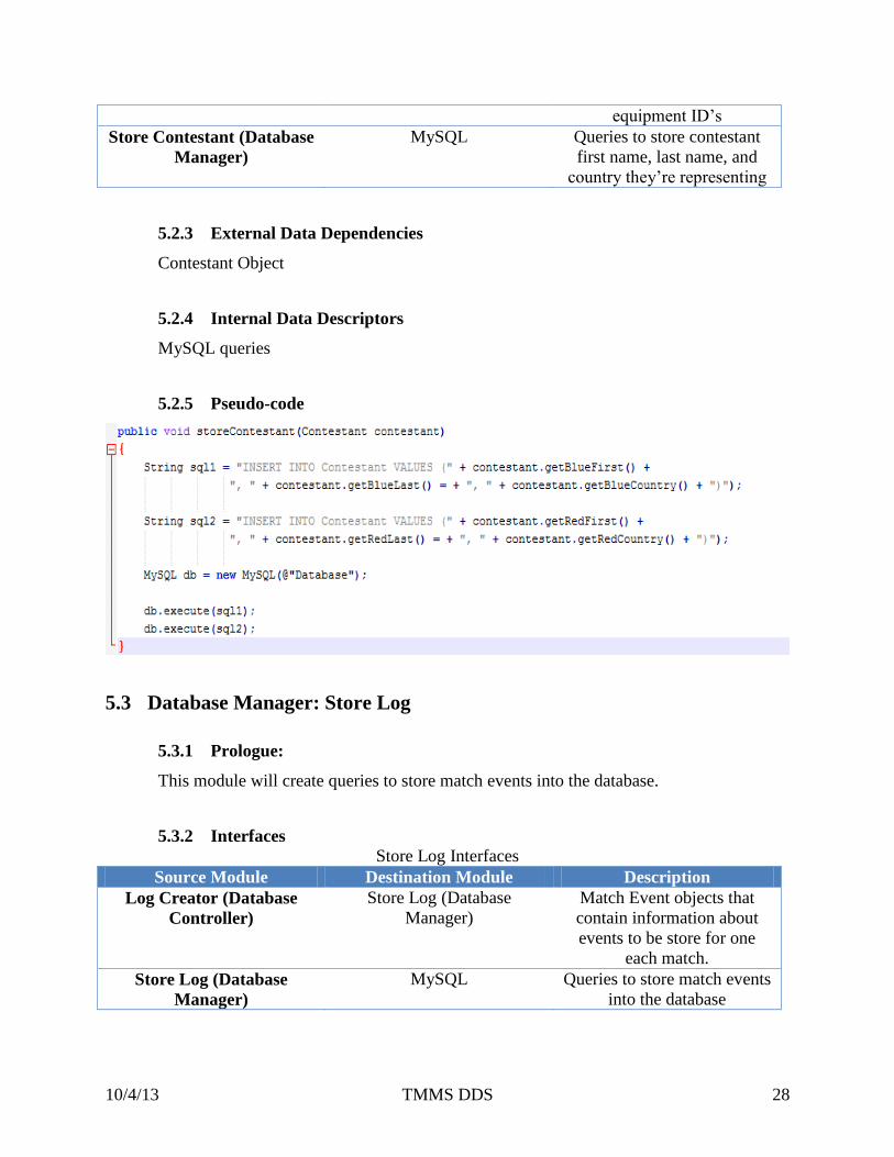
5.2.1 Prologue
This module will create a query that will store contestant information into the database.
5.2.2 Interfaces
Store Contestant Interfaces
Source Module Destination Module Description
DB Store (Database
Controller)
Store Contestant (Database
Manager)
Contestants first and last
name along with their
Page 28
10/4/13 TMMS DDS 28
equipment ID’s
Store Contestant (Database
Manager)
MySQL Queries to store contestant
first name, last name, and
country they’re representing
5.2.3 External Data Dependencies
Contestant Object
5.2.4 Internal Data Descriptors
MySQL queries
5.2.5 Pseudo-code
5.3 Database Manager: Store Log
5.3.1 Prologue:
This module will create queries to store match events into the database.
5.3.2 Interfaces
Store Log Interfaces
Source Module Destination Module Description
Log Creator (Database
Controller)
Store Log (Database
Manager)
Match Event objects that
contain information about
events to be store for one
each match.
Store Log (Database
Manager)
MySQL Queries to store match events
into the database
Page 29
10/4/13 TMMS DDS 29
5.3.3 External Data Dependencies
Match Event objects
5.3.4 Internal Data Descriptors
MySQL Queries
5.3.5 Pseudo-code
5.4 Database Manager: Retrieve Match Log
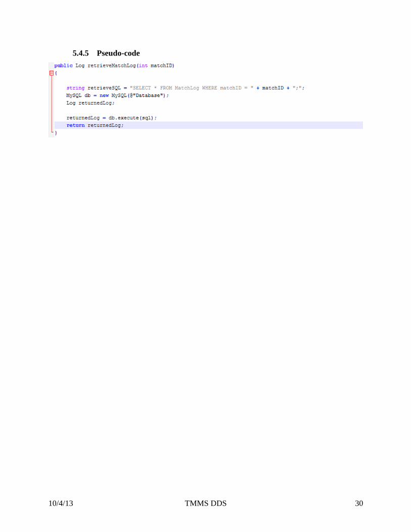
5.4.1 Prologue:
This module will create a query to request a match log from the database.
5.4.2 Interfaces
Retrieve Match Log Interfaces
Source Module Destination Module Description
Request Log (Database
Controller)
Retrieve Match Log
(Database Manager)
Match ID which identifies a
unique match in the database
Retrieve Match Log
(Database Manager)
MySQL Queries that request a specific
match log from the database
MySQL Retrieve Match Log
(Database Manager)
Match Log information from
the database
5.4.3 External Data Dependencies
Match ID
5.4.4 Internal Data Descriptors
MySQL Queries
Page 30
10/4/13 TMMS DDS 30
5.4.5 Pseudo-code
Page 31
10/4/13 TMMS DDS 31
6 Match Event Processor Layer
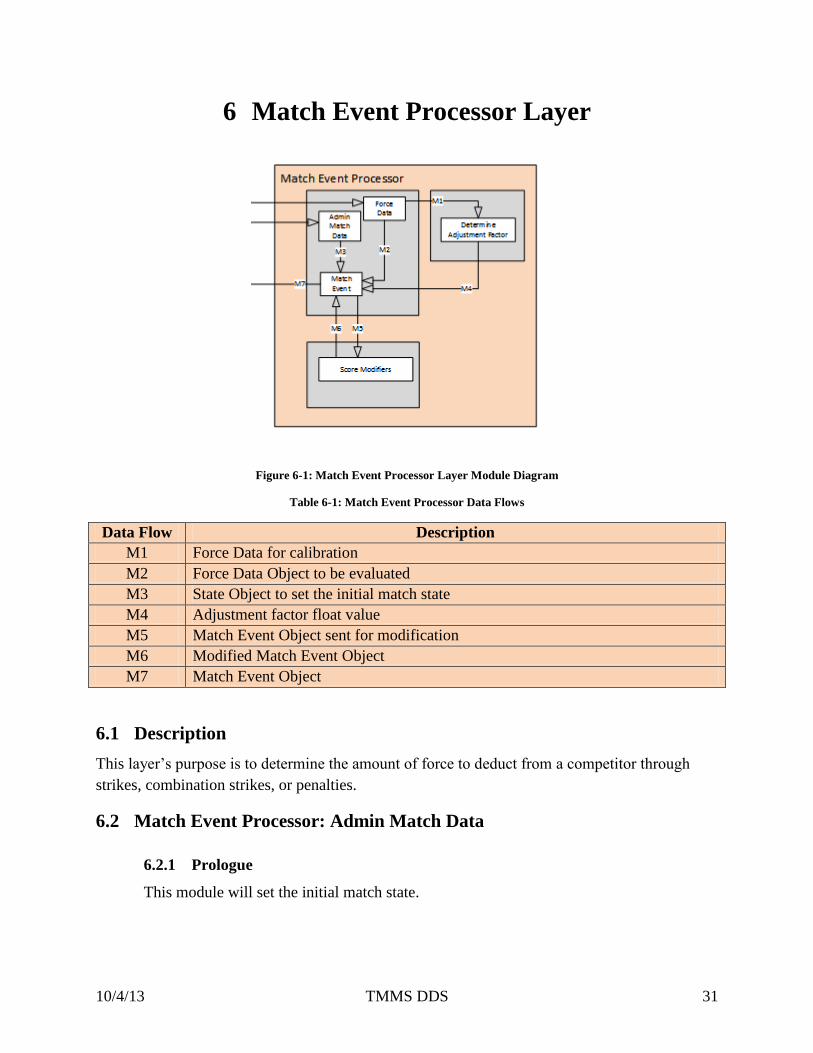
Figure 6-1: Match Event Processor Layer Module Diagram
Table 6-1: Match Event Processor Data Flows
Data Flow Description
M1 Force Data for calibration
M2 Force Data Object to be evaluated
M3 State Object to set the initial match state
M4 Adjustment factor float value
M5 Match Event Object sent for modification
M6 Modified Match Event Object
M7 Match Event Object
6.1 Description
This layer’s purpose is to determine the amount of force to deduct from a competitor through
strikes, combination strikes, or penalties.
6.2 Match Event Processor: Admin Match Data
6.2.1 Prologue
This module will set the initial match state.
Page 32
10/4/13 TMMS DDS 32
6.2.2 Interfaces
Source Module Destination Module Description
Time Controls Admin Match Data Object with timestamp
Admin Match Data Match Event Match Event Object
6.2.3 External Data Dependencies
This module will receive an Object with a timestamp
6.2.4 Internal Data Descriptors
This module will send a Match Event Object.
6.2.5 Pseudo-Code
6.3 Match Event Processor: Force Data
6.3.1 Prologue
This module will check to see if the force is for calibration or for a match.
6.3.2 Interfaces
Source Module Destination Module Description
Time Stamp Force Data Force Data Object with
timestamp
Force Data Determine Adjustment Factor Force Data Object with
calibration flag
Force Data Match Event Force Data Object
6.3.3 External Data Dependencies
This module receives a Force Data Object with a timestamp.
6.3.4 Internal Data Descriptors
This module sends a Force Data Object.
Page 33
10/4/13 TMMS DDS 33
6.3.5 Pseudo-Code
6.4 Match Event Processor: Match Event
6.4.1 Prologue
This module determines the legitimacy of a Match Event.
6.4.2 Interfaces
Source Module Destination Module Description
Force Data Match Event Force Object
Determine Adjustment
Factor
Match Event Adjustment Factor float for
calibration
Admin Match Data Match Event Initial Match State
Match Event Score Modifiers Send Match Event Object
Score Modifiers Match Event Receive Match Event Object
Match Event Match Log Send Match Event
6.4.3 External Data Dependencies
Must receive Force Object or Match State Object.
6.4.4 Internal Data Descriptors
Match Event Object.
Page 34
10/4/13 TMMS DDS 34
6.4.5 Pseudo-Code
6.5 Calibration: Determine Adjustment Factor
6.5.1 Prologue
This module returns a float value for calibration.
6.5.2 Interfaces
Source Module Destination Module Description
Force Data Determine Adjustment Factor Force Data Object
Determine Adjustment
Factor
Match Event Adjustment Factor float value
for calibration
6.5.3 External Data Dependencies
Must receive a Force Data Object.
6.5.4 Internal Data Descriptors
Will determine the adjustment factor for force values.
Page 35
10/4/13 TMMS DDS 35
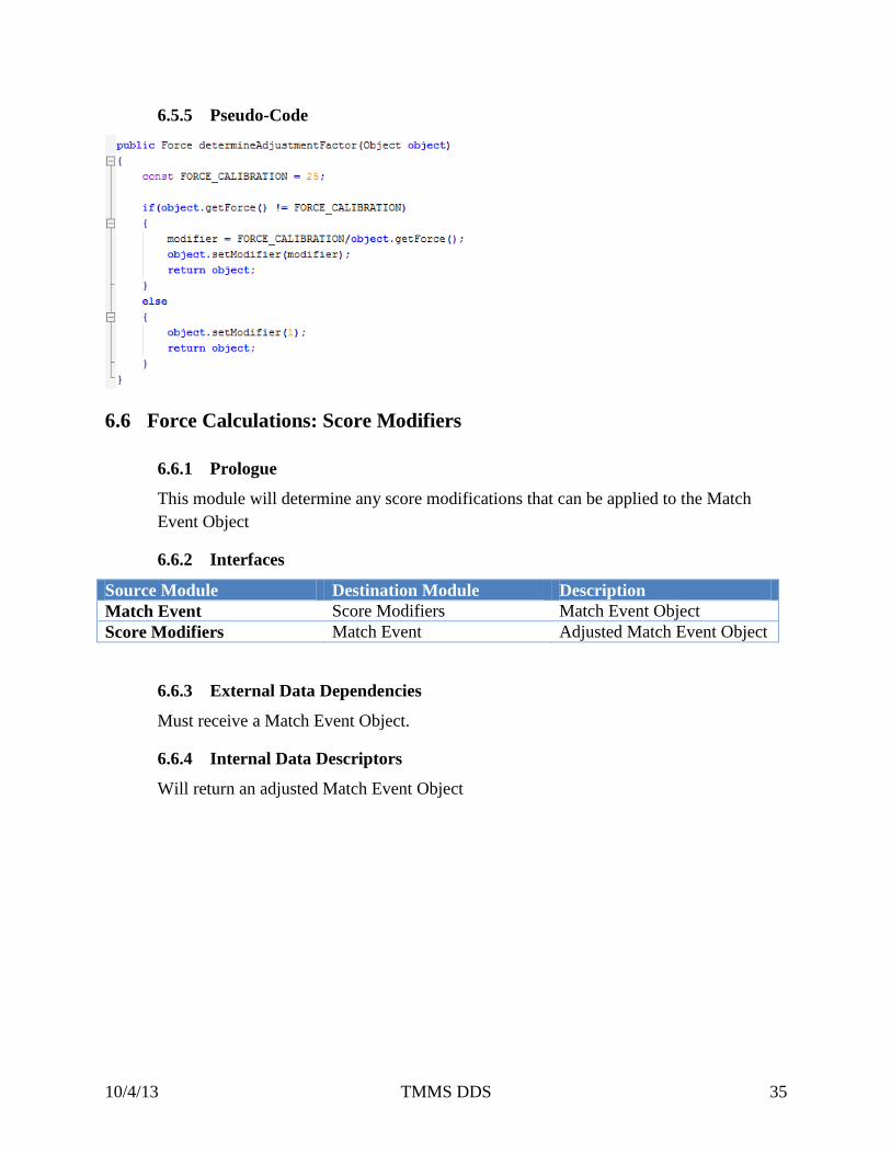
6.5.5 Pseudo-Code
6.6 Force Calculations: Score Modifiers
6.6.1 Prologue
This module will determine any score modifications that can be applied to the Match
Event Object
6.6.2 Interfaces
Source Module Destination Module Description
Match Event Score Modifiers Match Event Object
Score Modifiers Match Event Adjusted Match Event Object
6.6.3 External Data Dependencies
Must receive a Match Event Object.
6.6.4 Internal Data Descriptors
Will return an adjusted Match Event Object
Page 36
10/4/13 TMMS DDS 36
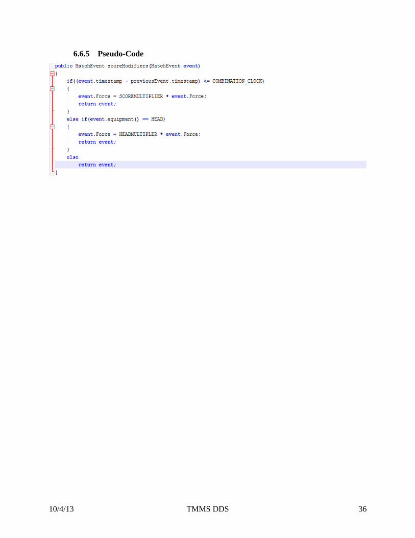
6.6.5 Pseudo-Code
Page 37
10/4/13 TMMS DDS 37
7 Presentation Layer
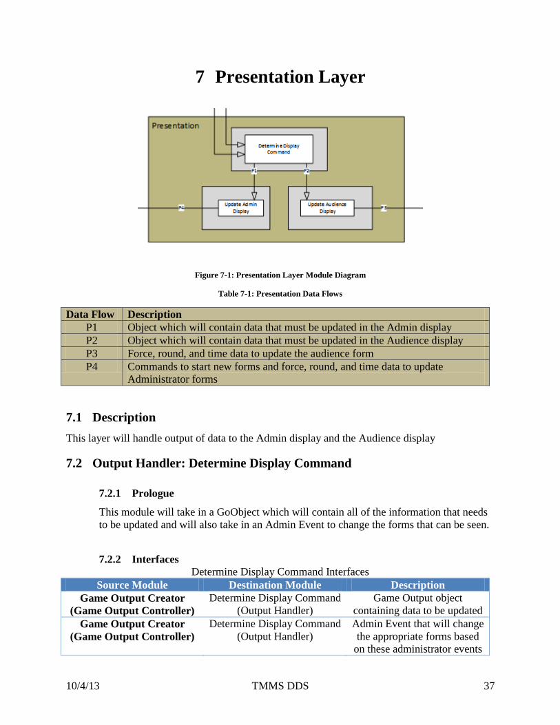
Figure 7-1: Presentation Layer Module Diagram
Table 7-1: Presentation Data Flows
Data Flow Description
P1 Object which will contain data that must be updated in the Admin display
P2 Object which will contain data that must be updated in the Audience display
P3 Force, round, and time data to update the audience form
P4 Commands to start new forms and force, round, and time data to update
Administrator forms
7.1 Description
This layer will handle output of data to the Admin display and the Audience display
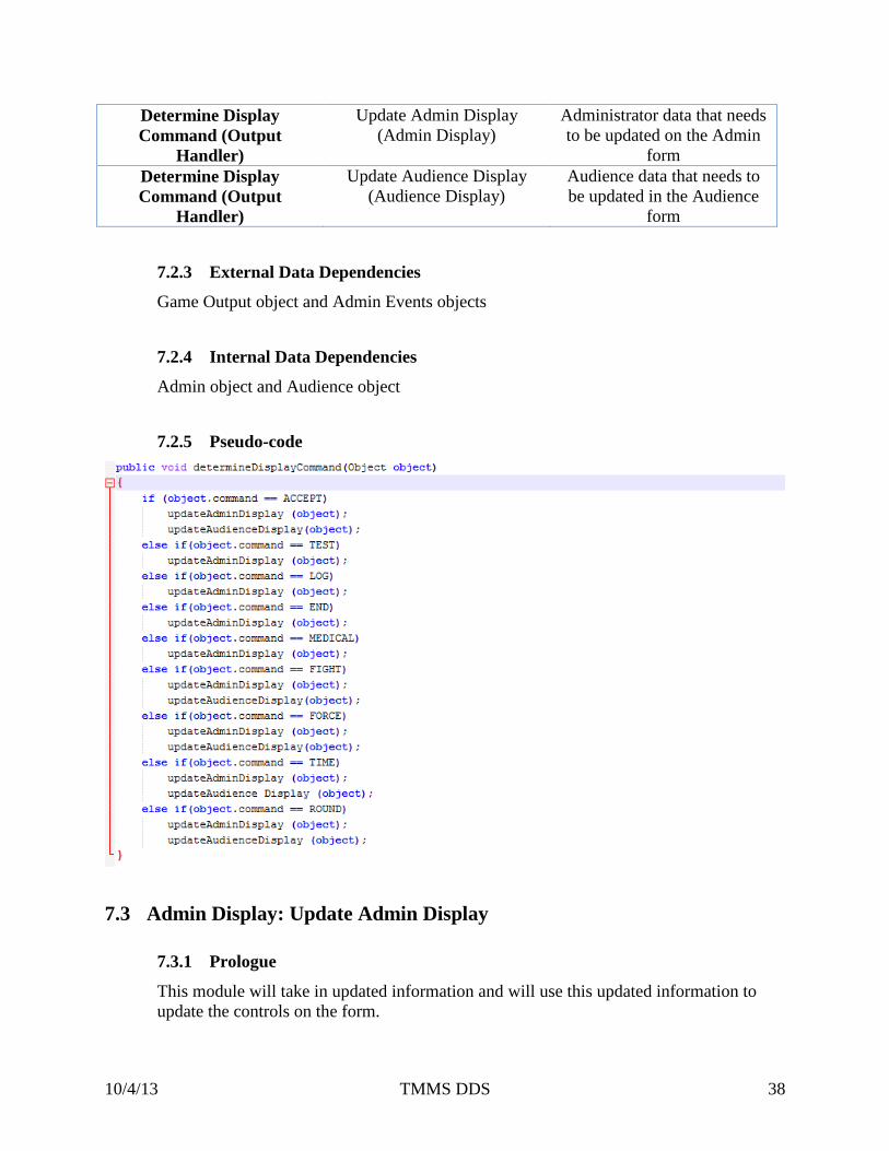
7.2 Output Handler: Determine Display Command
7.2.1 Prologue
This module will take in a GoObject which will contain all of the information that needs
to be updated and will also take in an Admin Event to change the forms that can be seen.
7.2.2 Interfaces
Determine Display Command Interfaces
Source Module Destination Module Description
Game Output Creator
(Game Output Controller)
Determine Display Command
(Output Handler)
Game Output object
containing data to be updated
Game Output Creator
(Game Output Controller)
Determine Display Command
(Output Handler)
Admin Event that will change
the appropriate forms based
on these administrator events
Page 38
10/4/13 TMMS DDS 38
Determine Display
Command (Output
Handler)
Update Admin Display
(Admin Display)
Administrator data that needs
to be updated on the Admin
form
Determine Display
Command (Output
Handler)
Update Audience Display
(Audience Display)
Audience data that needs to
be updated in the Audience
form
7.2.3 External Data Dependencies
Game Output object and Admin Events objects
7.2.4 Internal Data Dependencies
Admin object and Audience object
7.2.5 Pseudo-code
7.3 Admin Display: Update Admin Display
7.3.1 Prologue
This module will take in updated information and will use this updated information to
update the controls on the form.
Page 39
10/4/13 TMMS DDS 39
7.3.2 Interfaces
Update Admin Display Interfaces
Source Module Destination Module Description
Determine Display
Command (Output
Handler)
Update Admin Display
(Admin Display)
Admin object which contains
data that needs to be updated
in the administrator form
Update Admin Display
(Admin Display)
Administrator Screen Updated views
7.3.3 External Data Dependencies
Admin object
7.3.4 Internal Data Descriptors
None
7.3.5 Pseudo-code
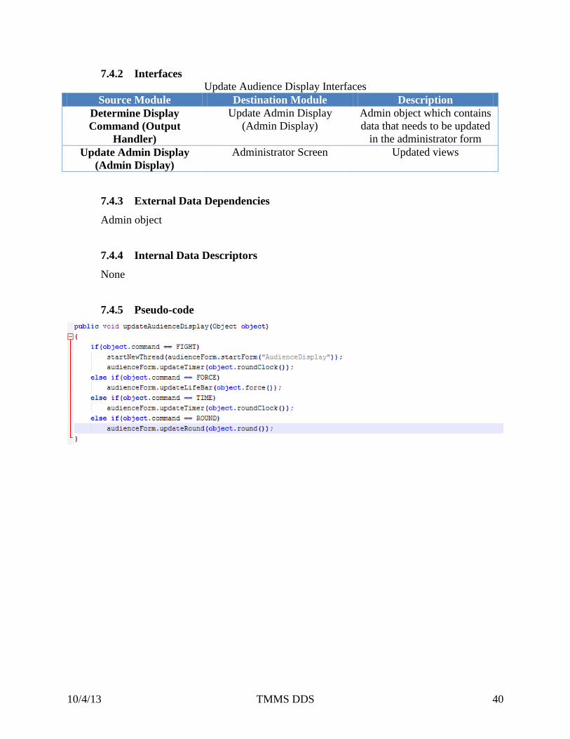
7.4 Audience Display: Update Audience Display
7.4.1 Prologue
This module will take in updated information such as the updated force, round, and time
to update the views on the Audience form that will be displayed on the Audience display.
Page 40
10/4/13 TMMS DDS 40
7.4.2 Interfaces
Update Audience Display Interfaces
Source Module Destination Module Description
Determine Display
Command (Output
Handler)
Update Admin Display
(Admin Display)
Admin object which contains
data that needs to be updated
in the administrator form
Update Admin Display
(Admin Display)
Administrator Screen Updated views
7.4.3 External Data Dependencies
Admin object
7.4.4 Internal Data Descriptors
None
7.4.5 Pseudo-code
Page 41
10/4/13 TMMS DDS 41
8 Quality Assurance
8.1 Test Plan and Procedures
The system architecture will be tested by team TK Force to ensure that all the functionalities and
system components are reviewed and tested based on the requirements defined in the System
Requirements Specification, Architecture Design Specification, and Detailed Design
Specification. Changes will be made to all the documents to ensure that every document have
been updated correctly. Each component will be tested individually and the system will also be
tested as a whole to verify that the integration of each individual component is properly made.
8.2 Module/Unit Test
8.2.1 Input Layer
8.2.1.1 Admin Input Subsystem: Keyboard/Mouse Input Module
This module shall be tested to ensure it correctly receives all keyboard and
mouse input from the Admin PC.
8.2.1.2 Input Packager Subsystem: Admin Package Module
This module shall be tested to ensure it will receive the text data and
admin commands, and use the input to correctly create the Admin Event
object, send the equipment IDs, and send a penalty command to the Force
Data Package Module.
8.2.1.3 Input Packager Subsystem: Force Data Package Module
This module shall be tested to ensure it correctly creates a Force Data
object from the Equipment Input Module.
Page 42
10/4/13 TMMS DDS 42
8.2.1.4 Equipment Input Subsystem: Filter Module
This module shall be tested to ensure that it will receive the equipment ID
from the Admin Package Module and match the IDs to only focusing on
receiving inputs from the desired equipment.
8.2.1.5 Equipment Input Subsystem: Equipment Input Module
This module shall be tested to ensure it will receive the equipment ID and
force data from the Filer Module and it will correctly create a Force Data
object.
8.2.2 Data Controller Layer
8.2.2.1 Input Controller Subsystem: Object Identifier Module
This module shall be tested to ensure it will take in Contestant objects,
State objects, Admin Event objects and Force objects. Then it shall be able
to determine correctly what kind of object it has and send that object to the
appropriate module for further processing.
8.2.2.2 Database Controller Subsystem: Request Log Module
This module shall be tested to ensure the function will make a request to
the Database Layer that will retrieve the match log for a specified match
and then send this information to the GoCreator.
8.2.2.3 Database Controller Subsystem: DB store Module
This module shall be tested to ensure it will receive the Contestant objects
from the Input Controller, and this module will prepare the information to
be input into the database.
8.2.2.4 Database Controller Subsystem: Log Creator Module
This module shall be tested to ensure the function will receive the stack
containing the logs of events that occurred during the match, and this
Page 43
10/4/13 TMMS DDS 43
module will pop off each Match Event object from the stack to send to the
Database Layer to be stored in the database.
8.2.2.5 Game Output Controller Subsystem: Game Output Creator Module
This module shall be tested to ensure it will create an output object
correctly which will contain all of the new information to be updated in
the Presentation Layer.
8.2.2.6 Match Event Controller Subsystem: Time Stamp Module
This module shall be tested to ensure it will get a timestamp correctly
from the timer and place a timestamp on each event that much be stored in
the database.
8.2.2.7 Match Event Controller Subsystem: Time Module
This module shall be tested to ensure it will create a new timer correctly
for each request from the Admin such as the round clock, medical clock,
and the break clock. It will also be tested to ensure it will create a new
thread correctly in order to update the clock.
8.2.2.8 Match Event Controller Subsystem: Match Log Module
This module shall be tested to ensure it will receive the match events from
the Match Event subsystem and it will create a stack of these objects
correctly to be sent to the Database Controller Layer.
8.2.3 Database Layer
8.2.3.1 Database Manager Subsystem: Store Competitor Module
This module shall be tested to ensure it will create a query correctly that
will store competitor information into the database.
Page 44
10/4/13 TMMS DDS 44
8.2.3.2 Database Manager Subsystem: Store Log Module
This module shall be tested to ensure it will create queries correctly to
store match events into the database.
8.2.3.3 Database Manager Subsystem: Retrieve Match Log Module
This module shall be tested to ensure it will create a query correctly to
request a match log from the database.
8.2.3.4 Data Storage Subsystem
8.2.4 Match Event Processor Layer
8.2.4.1 Match Event Processor Subsystem: Admin Match Data
This module shall be tested to ensure it set the initial match state correctly.
8.2.4.2 Match Event Processor Subsystem: Match Event
This module shall be tested to ensure it will correctly determine the
legitimacy of a Match Event.
8.2.4.3 Match Event Processor Subsystem: Force Data
This module shall be tested to ensure it will check to see if the force is for
calibration or for a match, and determine them correctly.
8.2.4.4 Match Calculations Subsystem: Score Modifiers
This module shall be tested to ensure it will correctly determine any score
modifications that can be applied to the Match Event objects.
Page 45
10/4/13 TMMS DDS 45
8.2.4.5 Calibration Subsystem: Determine Adjustment Factor
This module shall be tested to ensure it will return a float value correctly
for the Calibration subsystem.
8.2.5 Presentation Layer
8.2.5.1 Output Handler Subsystem: Determine Display Command
This module shall be tested to ensure it will take in a GoObject which will
contain all of the information that needs to be updated and will also take in
an Admin Event to change the forms that can be seen.
8.2.5.2 Admin Display Subsystem: Update Admin Display
This module shall be tested to ensure it will take in updated information
and will use this updated information to update the controls on the form
8.2.5.3 Audience Display Subsystem: Update Audience Display
This module shall be tested to ensure it will take in updated information
such as the updated force, round, and time to update the views on the
Audience form that will be displayed on the Audience display
8.3 Component Testing
8.3.1 E-Hogu & E-Headgear
The Hogu and Headgear shall be tested to ensure it returns correct data of the hit which
contains the force data. The Hogu and Headgear will be tested based on applying
different amount of forces on it and check the return data to see if the returned force
matches the force applied on the equipment.
8.3.2 Transmitters
The transmitters shall be tested to ensure the connections between the transmitter and
receiver is stable, and also, the data that transmitters sent to the receiver are in the
Page 46
10/4/13 TMMS DDS 46
correct format at a correct frequency. The signal strength will also be tested to ensure
during a match, every valid hit will be correctly taken into the system. The signal
strength will be tested based on the distance between the transmitters and receiver to
determine what the appropriate distance for the transmitters and receiver is.
8.3.3 Receiver
The receiver shall be tested to ensure it works correctly with the operating system. The
driver of the USB receiver will be tested for this. And also the connection between the
transmitters and receiver shall also be tested. The way to test this is same as how to test
the transmitters.
8.4 Integration Testing
Reference to the interfaces tables for every module, all the inputs shall be passed into
different modules from a specific module within the system. All the inputs must be in the
correct format and range. Every module within the system shall work correctly as long as the
inputs are in the correct format and range.
Every module in the system shall work separately from other modules, the only connection
between any modules shall only be input/output based. Based on this, the integration shall be
ensured as long as the data is in the correct format and range.
8.5 System Verification Testing
The system shall be subjected to a series of tests to verify fulfillment of all requirements
according to the system specifications. The system will be tested by the customer as a whole
in real world cases. Customer will inspect the system by using it to run matches. The
feedback of the customer will be the result of the system verification testing.
8.6 Test Cases
Table 8-1: Test Cases
Test case Expected Result
Hit the Hogu and Heargear without the
Foodgear.
Nothing should happen at all
Apply a force that’s lower than the
threshold.
Force shall be displayed, but no hit shall be
taken to impact the match.
Page 47
10/4/13 TMMS DDS 47
A valid hit is arrived on one competitor The life bar on the audience screen shall be
deducted; a record shall be made for the
log.
Hits during the Test Mode. The Test Mode screen shall display the
information about the hit, but no hit will be
taken into the log or the match.
Administrator click on the start fight
button.
The fight clock shall start to count down,
all valid hits shall be recorded and have
impacts to the match.
Administrator click on the pause button. The fight clock shall stop counting down.
No hits will be taken into the system to
have impact to the match.
Administrator click on the medical
button
The fight shall pause and medical clock
shall start to count down.
Page 48
10/4/13 TMMS DDS 48
9 Requirements Mapping
9.1 Purpose
9.2 Layer Requirements Traceability
9.2.1 Customer requirements
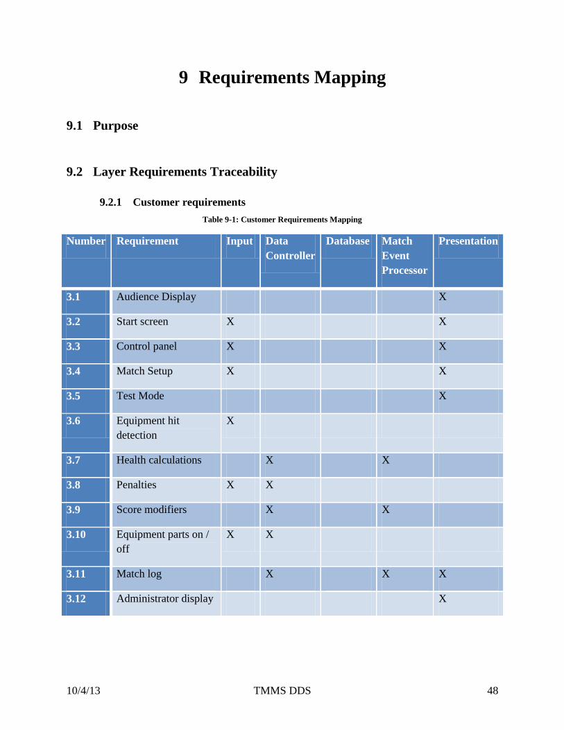
Table 9-1: Customer Requirements Mapping
Number Requirement Input Data
Controller
Database Match
Event
Processor
Presentation
3.1 Audience Display X
3.2 Start screen X X
3.3 Control panel X X
3.4 Match Setup X X
3.5 Test Mode X
3.6 Equipment hit
detection
X
3.7 Health calculations X X
3.8 Penalties X X
3.9 Score modifiers X X
3.10 Equipment parts on /
off
X X
3.11 Match log X X X
3.12 Administrator display X
Page 49
10/4/13 TMMS DDS 49
9.2.2 Performance requirements
Table 9-2: Performance Requirements Mapping
Number Requirement Input Data
Controller
Database Match
Event
Processor
Presentation
5.1 Start Program X
5.2 Life bar deduction
response
X X X
5.3 Recording log X X
5.4 Response to button
clicks
X X
5.5 Processing force data X
9.2.3 Other requirements
Table 9-3: Other Requirements Mapping
Number Requirement Input Data
Controller
Database Match
Event
Processor
Presentation
8.1 Store contestant
information
X
8.2 Store match events X
8.3 Store country
information
X
8.4 Store match statistics X
8.5 Calibration X X
Page 50
10/4/13 TMMS DDS 50
9.3 Module Requirements Traceability
Table 9-4: Customer Requirements Mapping
Req 3.1 3.2 3.3 3.4 3.5 3.6 3.7 3.8 3.9 3.10 3.11 3.12
Keyboard/Mouse
Input X X X X X
Filter X
Equipment Input X X
Admin Package X X X
Force Data
Package X
Object Identifier X X X
Request Log
DB Store
Log Creator X
Time Stamp X X
Time Module X
Match Log X
Game Output
Creator
Store Competitor
Store Log
Retrieve Match
Log
Admin Match
Data
Force Data X
Match Event X
Determine
Adjustment
Factor
X
Score Modifiers X X X
Determine
Display
Command
X X X X X X X
Update Admin
Display X X X X X X
Update
Audience
Display
X
Page 51
10/4/13 TMMS DDS 51
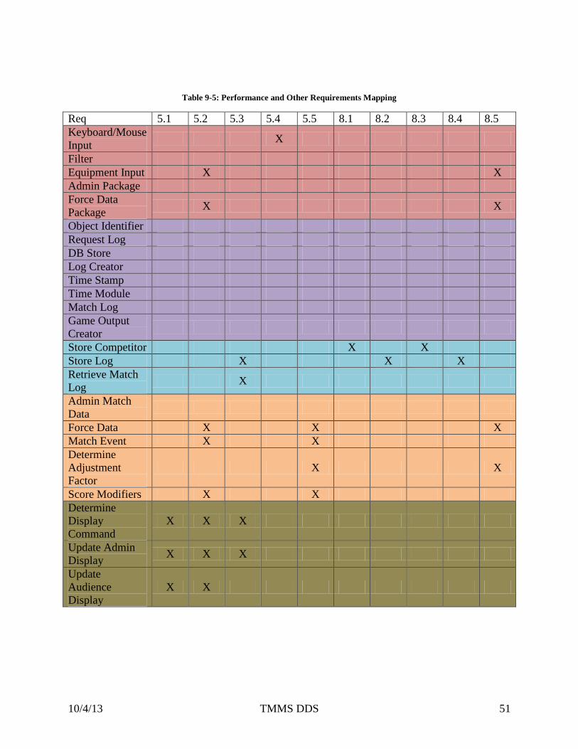
Table 9-5: Performance and Other Requirements Mapping
Req 5.1 5.2 5.3 5.4 5.5 8.1 8.2 8.3 8.4 8.5
Keyboard/Mouse
Input X
Filter
Equipment Input X X
Admin Package
Force Data
Package X X
Object Identifier
Request Log
DB Store
Log Creator
Time Stamp
Time Module
Match Log
Game Output
Creator
Store Competitor X X
Store Log X X X
Retrieve Match
Log X
Admin Match
Data
Force Data X X X
Match Event X X
Determine
Adjustment
Factor
X X
Score Modifiers X X
Determine
Display
Command
X X X
Update Admin
Display X X X
Update
Audience
Display
X X
Page 52
10/4/13 TMMS DDS 52
10 Acceptance Plan
10.1 Overview
This section describes the minimum criteria that must be met by the sponsor in order to be
considered acceptable by the customers.
10.2 Packaging and Installation
10.2.1 Packaging Components:
10.2.1.1 Installation Disk
The executable file for installing the software will be putting on a CD to
distribute.
10.2.1.2 User Manual
A detailed user manual about the software will be made available on the
installation disk. It will address the frequently asked question and troubleshooting
tips.
10.2.2 Installation:
The software can be installed with an executable file.
10.3 Acceptance Testing
System testing shall be conducted to ensure that the system meets the acceptance criteria.
The system shall go through module, subsystem, layer, integration and overall system testing.
The details of the testing shall be provided in the System Test Plan document.
Page 53
10/4/13 TMMS DDS 53
10.4 Acceptance Criteria
10.4.1 Verify that the system displays the audience screen.
10.4.1.1 Requirement(s) addressed
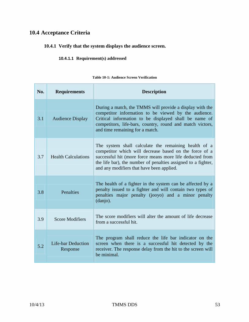
Table 10-1: Audience Screen Verification
No. Requirements Description
3.1 Audience Display
During a match, the TMMS will provide a display with the
competitor information to be viewed by the audience.
Critical information to be displayed shall be name of
competitors, life-bars, country, round and match victors,
and time remaining for a match.
3.7 Health Calculations
The system shall calculate the remaining health of a
competitor which will decrease based on the force of a
successful hit (more force means more life deducted from
the life bar), the number of penalties assigned to a fighter,
and any modifiers that have been applied.
3.8 Penalties
The health of a fighter in the system can be affected by a
penalty issued to a fighter and will contain two types of
penalties major penalty (jooyo) and a minor penalty
(danjo).
3.9 Score Modifiers The score modifiers will alter the amount of life decrease
from a successful hit.
5.2 Life-bar Deduction
Response
The program shall reduce the life bar indicator on the
screen when there is a successful hit detected by the
receiver. The response delay from the hit to the screen will
be minimal.
Page 54
10/4/13 TMMS DDS 54
10.4.1.2 Verification Procedure
TMMS will be tested to ensure that the system can display the audience screen. After the
match has been setup, the audience screen will be displayed on the monitor.
10.4.2 Verify that the system runs in real time
10.4.2.1 Requirement(s) addressed:
Table 10-2: Real Time Verification
No. Requirements Description
5.2 Life-bar Deduction
Response
The program shall reduce the life bar indicator on the
screen when there is a successful hit detected by the
receiver. The response delay from the hit to the screen
will be minimal.
5.3 Recording Log The program shall record the logs of a match
immediately.
5.4 Response to Button
Click
The program shall respond to any button clicks
immediately.
10.4.2.2 Verification Procedure:
When the system and equipment are online, the pad of each competitor will be struck to
verify the life bar response. From the match log, the first event will be selected and
applied to ensure the match log reverts to the initial match state.
Page 55
10/4/13 TMMS DDS 55
10.4.3 Verify that the system saves data for Log
10.4.3.1 Requirement(s) addressed:
Table 10-3: Save Log Data Verification
No. Requirements Description
3.11 Match Log
The system shall store the history of all scoreboard
changing events and their attributes. If you select an
event in the match log and hit accept, the match will be
reverted to that point.
8.2 Store Match Events
This information will be stored in a database and will
correspond to events that affect the score in a single
match. This information may also be used to return a
match to a specific point in time.
8.3 Store Match Statistics
This is a list of countries represented in the Olympic
Games. Must be stored in a database as 3 letter country
code, and must store corresponding country flag.
10.4.3.2 Verification Procedure:
TMMS will be tested and verified that the system responds to the match and store all the
logs immediately.
10.4.4 Verify that the system is user friendly
10.4.4.1 Requirement(s) addressed:
Table 10-4: User Friendliness Verification
No. Requirements Description
Page 56
10/4/13 TMMS DDS 56
3.2 Start Screen When the system is started the software shall display a start
screen showing the logo and name of the system.
3.3 Control Panel
The system shall have a control panel that allows a user to view
details about a match, apply test mode for a match, apply minor
and major penalties, apply medical to a match, and alter details
about a match.
3.4 Match Setup
The system shall have a match setup screen to input contestant
information, register equipment to contestant, and specify other
match information.
3.5 Test Mode The system shall have a mode for users to view the forces that
occur during a match and the times the forces occurred.
3.8 Penalties
The health of a fighter in the system can be affected by a
penalty issued to a fighter and will contain two types of
penalties major penalty (jooyo) and a minor penalty (danjo).
3.9 Score Modifiers The score modifiers will alter the amount of life decrease from a
successful hit.
3.11 Match Log
The system shall store the history of all scoreboard changing
events and their attributes. If you select an event in the match
log and hit accept, the match will be reverted to that point.
10.4.4.2 Verification Procedure:
TMMS will be tested by the sponsor to verify ease of use.
Page 57
10/4/13 TMMS DDS 57
10.4.5 Verify that the system is accurately recording force
10.4.5.1 Requirement(s) addressed:
Table 10-5: Force Accuracy Verification
No. Requirements Description
3.5 Test Mode
The system shall have a mode for users to view the forces
that occur during a match and the times the forces
occurred.
3.7 Health Calculations
The system shall calculate the remaining health of a
competitor which will decrease based on the force of a
successful hit (more force means more life deducted from
the life bar), the number of penalties assigned to a fighter,
and any modifiers that have been applied.
5.3 Processing Force Data
When a hit is registered by the program, the force
recorded from the hit will be retrieved from the Daedo
equipment.
9.5 Calibration This will allow the force of hits on the equipment to be
adjusted to ensure accuracy.
10.4.5.2 Verification Procedure:
TMMS will be tested after calibration to ensure the force of the hits is accurate.
Page 58
10/4/13 TMMS DDS 58
11 Hardware Components
11.1 Overview
This section describes all the hardware components will be used in the Taekwondo Match
Management System (TMMS). Each components purpose, specifications and interface will be
describe in blow.
11.2 EPRO 2910 Daedo E-Hogu w/out transmitter
Figure 11-1: EPRO 2910 Daedo E-Hogu w/out transmitter
11.2.1 Purpose
The purpose of having these two chest protector is to capture hit information from chest-
hit during the match.
11.2.2 Specifications
Resistant proximity and impact sensors
Sensors only activates when the magnet in the foot-pad in close
Send captured information through Ethernet cable
Reversible red and blue sides
11.2.3 Interfaces
The EPRO 2910 Daedo E-Hogu will interface with the wireless transmitter that
connected to the Ethernet cable.
Page 59
10/4/13 TMMS DDS 59
11.3 EPRO 2913 Daedo E-Headgear w/out transmitter
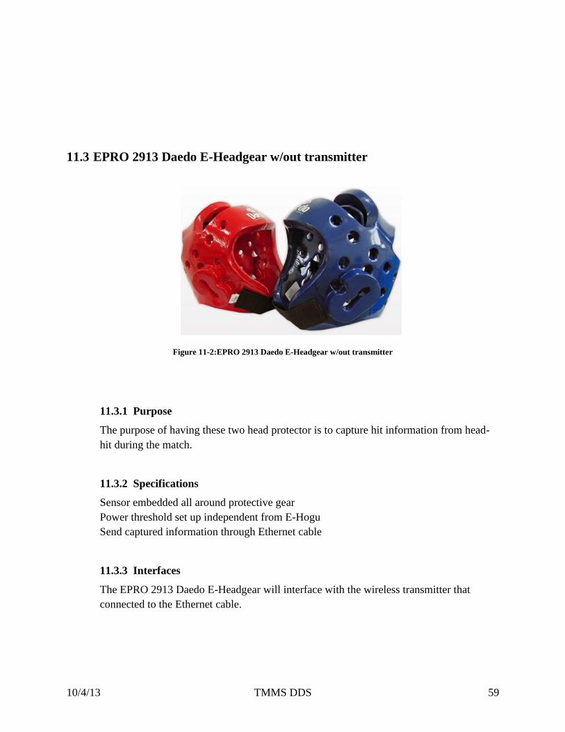
Figure 11-2:EPRO 2913 Daedo E-Headgear w/out transmitter
11.3.1 Purpose
The purpose of having these two head protector is to capture hit information from head-
hit during the match.
11.3.2 Specifications
Sensor embedded all around protective gear
Power threshold set up independent from E-Hogu
Send captured information through Ethernet cable
11.3.3 Interfaces
The EPRO 2913 Daedo E-Headgear will interface with the wireless transmitter that
connected to the Ethernet cable.
Page 60
10/4/13 TMMS DDS 60
11.4 EPRO 2903 Daedo E-Footgear
Figure 11-3: EPRO 2903 Daedo E-Footgear
11.4.1 Purpose
The purpose of having E-Footgear is to register hit to other equipment. A hit can only be
registered with E-Footgear.
11.4.2 Specifications
Magnet pads built in
Magnet pads activates other sensor to register hit
11.4.3 Interfaces
The EPRO 2903 Daedo E-Footgear interfaces with EPRO 2910 Daedo E-Hogu and
EPRO 2913 Daedo E-Headgear to register hit.
Page 61
10/4/13 TMMS DDS 61
11.5 EPRO 2909 Daedo E-Hogu & E-Headgear Wireless Transmitter
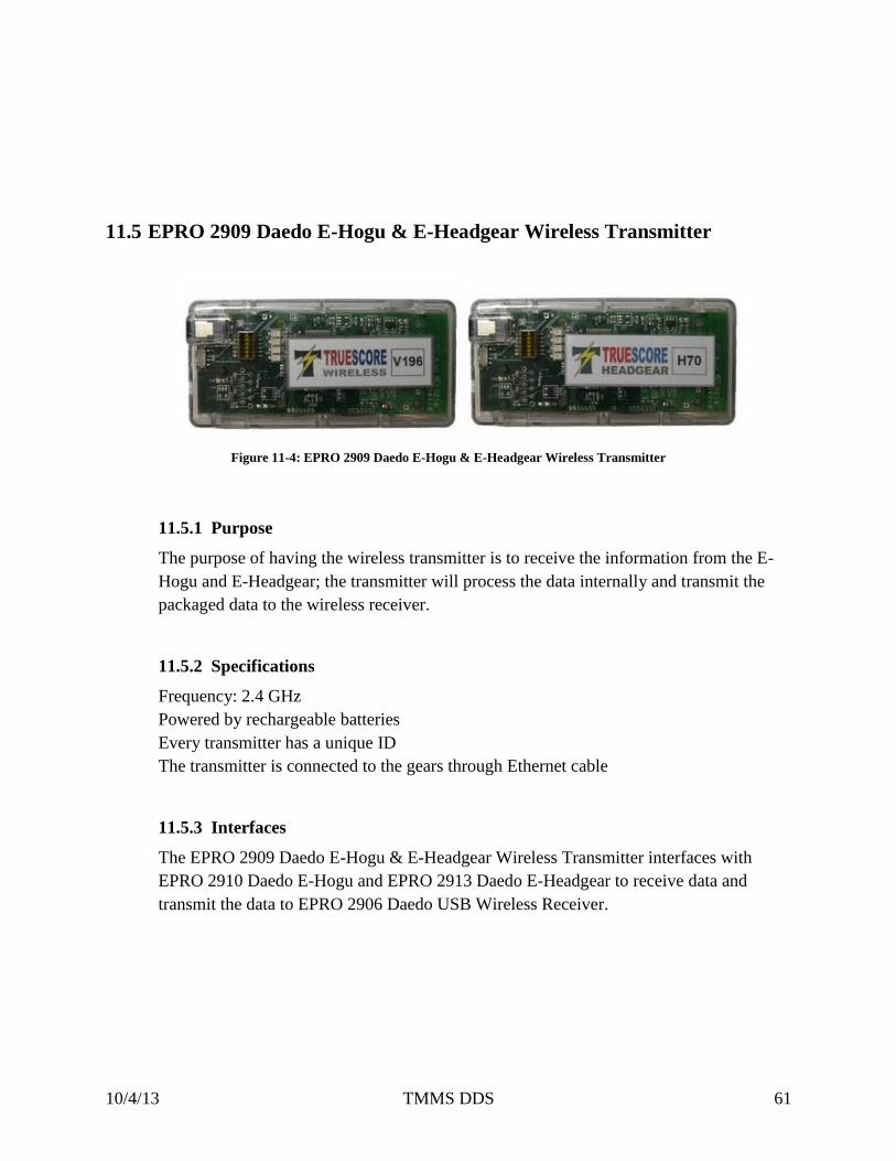
Figure 11-4: EPRO 2909 Daedo E-Hogu & E-Headgear Wireless Transmitter
11.5.1 Purpose
The purpose of having the wireless transmitter is to receive the information from the E-
Hogu and E-Headgear; the transmitter will process the data internally and transmit the
packaged data to the wireless receiver.
11.5.2 Specifications
Frequency: 2.4 GHz
Powered by rechargeable batteries
Every transmitter has a unique ID
The transmitter is connected to the gears through Ethernet cable
11.5.3 Interfaces
The EPRO 2909 Daedo E-Hogu & E-Headgear Wireless Transmitter interfaces with
EPRO 2910 Daedo E-Hogu and EPRO 2913 Daedo E-Headgear to receive data and
transmit the data to EPRO 2906 Daedo USB Wireless Receiver.
Page 62
10/4/13 TMMS DDS 62
11.6 EPRO 2906 Daedo USB Wireless Receiver
Figure 11-5:EPRO 2906 Daedo USB Wireless Receiver
11.6.1 Purpose
The purpose of having this USB wireless receiver is to receive the match event
information from the wireless transmitter and send the information to the system through
USB port.
11.6.2 Specifications
Frequency: 2.4 GHz
Receives data from
Send captured information through Ethernet cable
11.6.3 Interfaces
The EPRO 2906 Daedo USB Wireless Receiver will interface with the wireless
transmitter that connected to the Ethernet cable.
Page 63
10/4/13 TMMS DDS 63