24
ArcelorMittal Sheet Piling ArcelorMittal Sheet Piling Detailed Design | The Netherlands Part 1 | Technical & Cost Analysis Underground car parks Mobility Infrastructure Solutions

ArcelorMittal Sheet PilingArcelorMittal Sheet Piling
Detailed Design | The NetherlandsPart 1 | Technical & Cost Analysis
Underground car parks
Mobility Infrastructure Solutions

Disclaimer
The economic analysis was performed by the Dutch consulting engineers Witteveen + Bos (W+B) for ArcelorMittal in 2020. The design assumptions were determined for an underground car park in soil conditions that are encountered in downtown Amsterdam, the Netherlands.
ArcelorMittal emphasizes on the fact that W+B has performed an objective and unbiased case study. The analysis is a purely hypothetical case study with its limitations on reliability on costs and techniques, since these aspects can be very dynamic in markets and different subsoils.
This case study is not a project specific design, therefore neither ArcelorMittal nor Witteveen + Bos can be held responsible for choices made in specific projects based on the design or conclusions of the report prepared by W+B.
The text in this brochure is a summary of the report. It was edited in order to focus on the key points of the report with a minimum of technical explanations, except for the fire design which is explained more in detail. Although the content and conclusions are in line with the original report, ArcelorMittal’s engineers added some remarks and comments which complement the information contained in the original report. Some figures, tables and sketches were edited, removed or replaced by new ones prepared by ArcelorMittal. In case of errors in the transcription, only the text and other elements from the original report by W+B are binding.
The original report from W+B is available on request.

Table of content
PART 1 Technical & Cost Analysis
1. Introduction 3
2. Geotechnical design 4 2.1. Soil data 4 2.2. Geohydrological data 4 2.3. Geometrical data 4 2.4. Practical aspects 5 2.5. Safety philosophy 5 2.6. Design software 5 2.7. Underwater concrete slab 5 2.8. Phases 6
3. Retaining walls 7 3.1. Sheet pile wall 7 3.2. Diaphragm wall 8 3.3. Soilmix wall 9 3.4. Secant pile wall 10 3.5. Overview retaining wall characteristics 10
4. Fire safety 11 4.1. Introduction 11 4.2. Fire scenario and temperature loads 11 4.3. Sheet pile wall 12 4.4. Diaphragm wall 12 4.5. SoilMix wall 13 4.6. Secant pile wall 13 4.7. Conclusion 13
5. Key indicator - Cost 14
6. Impact of wall type on planning and cashflow 16
7. Summary 17
8. References 19

22
Urban development is facing many challenges due to the faster increase of the population in the cities compared to the increase of available (affordable) housing. Some major cities are struggling to find an equilibrium between growth and well-being of the citizen. Noise and traffic jams close to jobsites are also a negative aspect of construction, so that once a new construction project starts, speed of execution is a key indicator to include already in the design phase. Steel elements have the advantage of being delivered to the job-site as prefabricated elements that can be erected quickly and directly submitted to the design actions. Based on experience, the speed of execution can be two times faster for steel elements such as sheet piles. Nowadays, the construction costs are not anymore the only factor to be considered. In some countries environmental and social criteria have already been implemented in the procurement process, mainly for public tenders.
In 2018, ArcelorMittal launched a market analysis on underground car parks, mandating the consulting engineers Royal Haskoning DHV in the Netherlands to elaborate a guide book, with a special focus on the Dutch habits and customs. The guide book [a] provides an overview of the common practice in the Netherlands regarding design, installation and permanent application of steel sheet piles for underground car parks.
In 2019, ArcelorMittal contracted Witteveen + Bos (W+B), a consulting engineering firm in the Netherlands, to dive into this topic and to make a detailed comparison of several alternatives for building the retaining wall of underground car parks (UCP) in typical Dutch soil conditions, with the groundwater table at shallow depth. The case study considers a two level UCP, built with the standard bottom-up method to execute a strutted retaining wall with a concrete bottom slab poured underwater.
In a second phase, based on the results of the case study, a Life Cycle Analysis (LCA) will be made in order to incorporate the carbon footprint into the selection of the solution, leading to the lowest Total Life Cycle Cost, including the burdens or benefits of the end of life (dismantling, recycling of the building elements). The LCA will be peer-reviewed by an independent expert. We believe that an LCA is a quite fair and transparent method to compare different solution and suppliers, preferably based on specific Environmental Product Declaration (EPD) from the producers rather than generic data from databases.
The choice of a solution shall consider several key indicators, the principal one being the construction cost (including the design). The cost indicator of the analysis performed by W+B is summarized in the table below. The case study had two levels below ground, but the results would be quite similar for a 3 levels UCP. Note that the conclusions cannot be simply transposed to other situations, nor to other countries, without applying a correction factor.
The sheet pile wall is the most cost-effective solution, the difference being around 40% compared to the Cutter Soil Mix (CSM) wall, around 50% compared to the secant pile wall and more than 150% compared to the diaphragm wall (D-Wall).
1.36
3.52
1.872.05
+159%
+38%+51%
0%
20%
40%
60%
80%
100%
120%
140%
160%
180%
200%
Sheet Piles Diaphragm wall CSM wall Secant Piles0.00
0.50
1.00
1.50
2.00
2.50
3.00
3.50
4.00
Milli
on E
uros
(M
€)
Cost comparison of the retaining wall (M€-%) Underground car parks NL - Case study W+B 2019
Cost Unit Sheet Piles D-Wall CSM Secant Piles
Wall M€ 1.36 3.52 1.87 2.05
Difference reference + 159% + 38% + 51%
PART 1 Technical & Cost Analysis
M€ = million Euros
In this case study, the steel sheet pile solution is at least 38 % more cost-effective for the retaining wall of the Underground Car Park with 2 levels below grade.
3
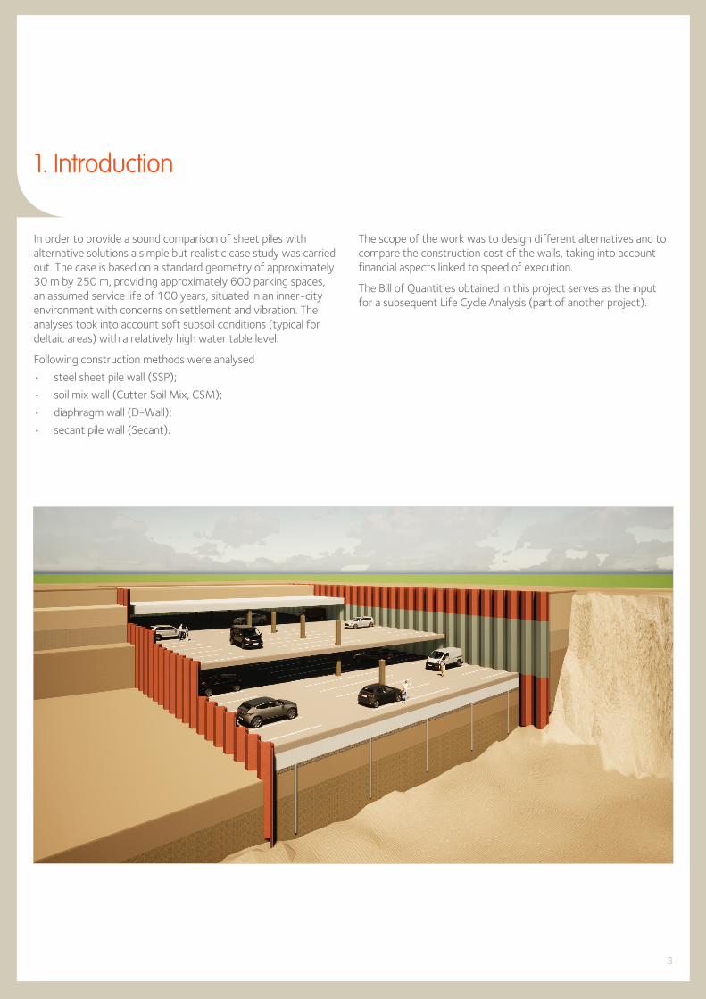
1. Introduction
In order to provide a sound comparison of sheet piles with alternative solutions a simple but realistic case study was carried out. The case is based on a standard geometry of approximately 30 m by 250 m, providing approximately 600 parking spaces, an assumed service life of 100 years, situated in an inner-city environment with concerns on settlement and vibration. The analyses took into account soft subsoil conditions (typical for deltaic areas) with a relatively high water table level.
Following construction methods were analysed
• steel sheet pile wall (SSP);
• soil mix wall (Cutter Soil Mix, CSM);
• diaphragm wall (D-Wall);
• secant pile wall (Secant).
The scope of the work was to design different alternatives and to compare the construction cost of the walls, taking into account financial aspects linked to speed of execution.
The Bill of Quantities obtained in this project serves as the input for a subsequent Life Cycle Analysis (part of another project).

4
2.1. Soil data
The soil strata considered in the design is presented in table 2.1. This soil profile is typical for deltaic areas, where soft subsoil is usually present the first 10 m or so.
2. Geotechnical design
Level top[m]
Soil type gunsat
[kN/m3]gsat
[kN/m3]j
[°]c’
[kPa]
0.0 clay, soft 15.0 15.0 15.0 0.0
-4.0 peat 12.0 12.0 15.0 2.5
-6.0 clay, firm 16.0 16.0 22.5 5.0
-12.0 sand 18.0 20.0 32.5 0.0
Table 2.1. Soil profile, typical for deltaic areas.
clayγ=15/15 kN/m3 c=0 kPa ϕ=15°
peatγ=12/12 kN/m3 c=2.5 kPa ϕ=15°
clay, firmγ=16/16 kN/m3 c=5 kPa ϕ=22.5°
sand, denseγ=18/20 kN/m3 c=0 kPa ϕ=32.5°
sand (backfill)
2.6
2.6
0.5
0.5
1.0
0.3
1.0
2.0
0.0 m
-1.0 m
-2.0 m
-3.0 m
-5.6 m
-6.1 m
-8.7 m
-9.2 m
-10.2 m-10.5 m
-14.0 m
-4.0 m
-6.0 m
-12.0 m
Figure 2.1. Cross section of the UCP.
2.2. Geohydrological dataThe water level is supposed to be 1 m below surface.
2.3. Geometrical data
The outer dimensions of the garage are 30 m x 250 m. The minimum clearance outline in garages is 2.3 m. On top of that another 0.3 m is needed for installations etc. The garage is designed to have 2 parking levels, and the roof should begin 2 m below surface, so that in the future utilities (cables and pipes) can be placed above the garage.
Assuming one row of columns in the middle of the structure, the span is equal to 15 m. The structure has following dimensions (height)
• roof: 0.8 m – 1.0 m;
• slab: 0.4 m – 0.5 m;
• underwater concrete slab: 0.8 m – 1.0 m;
• extra 0.2 – 0.3 m of gravel underneath the underwater concrete slab.
These large dimensions are chosen to make the construction robust, leading to an excavation depth of 10.5 m. The geometry is presented in Figure 2.1.
A variable surcharge load of 20 kPa is introduced on the ground surface.

5
2.4. Practical aspects
The construction is executed with the “bottom-up” sequence, working (excavating) under water until the underwater concrete slab is placed. This is the logical choice when surface availability is not an issue for one or two years. Only in extreme restrictions on surface availability one would choose for “top-down” construction, since this method consequently means hoisting limitations, working in confined space, limits on air quality etc. Inner-City Station boxes of the Amsterdam North South Line have been built top-down, given the huge impact on the traffic at surface and problems with buoyancy at the deepest excavation (pressurised excavation). It implied an increase on costs and duration.
At least two layers of struts are introduced, one above and one below the water level. Since the building site is located in the middle of an urban area, control of deformations is crucial. The deformations of retaining walls may cause damage to surrounding structures. There is no code in the Netherlands prescribing the maximum allowed deformation, but it is standard practice to accept 1/200 of the retaining height for maximum allowable deformation of the wall, with a maximum of 50 mm.
Figure 2.2. Software used for the design of the retaining walls.
2.5. Safety philosophy
The retaining wall is designed in accordance with the European design code Eurocode 7, Design Approach 1 (DA 1, combination 1 and 2), which is the design approach imposed in the Netherlands.
The governing conditions that are considered are displacements and bending moments (and crack width where applicable).
2.6. Design software
The retaining wall is designed using D-Sheet Piling software (version 18.1) from Deltares. This is the most common software used for designing retaining walls in the Netherlands.
To reduce the deformations, the first level of struts is placed before excavation starts. The use of struts (and girders) is inevitable in urban area, regardless of the chosen wall type. The strut system will not differ much between different wall types, since the forces in the struts will be similar.
It is less favourable to introduce anchors instead of struts, since the construction takes place in the middle of an urban area (founded on piles). The chance of underground objects that stand in the way, like foundations, cables, pipes etc. is high. Furthermore, using anchors could lead to legal issues since it is usually not allowed to leave objects in the ground outside of the borders of one’s property. However, anchors should not affect the choice of the wall type. Anchors can lead to an extra vertical load on the wall, but this load is assumed to be bearable by all the considered wall types. It is possible that this choice leads to extra sheet pile wall length (one extra meter of sheet pile length in sand layers generates approximately 100 kN bearing capacity, since horizontal equilibrium also requires a good sand layer). Alternatively, the sheet piles could be welded together, generating bearing capacity from the intermediate sheet piles as well.
Passive and active earth pressures coefficients are calculated assuming curved slip surfaces (Kötter). A surcharge of 20 kPa is taken into account on the active side.
2.7. Underwater concrete slab
The concrete is modelled as an extra soil layer. The Young’s modulus of the concrete is E = 20 GPa and the width of the pit excavation is b = 30 m. The subgrade reaction modulus of the concrete layer of K = E / (b/2), which is approximately 106 kN/m3, is taken into account in the design.
The unit weight of the concrete is not zero, but it is modelled as almost zero because it is assumed that the floor’s weight is transmitted to the support piles (slab is supported by tension piles during construction phase in order to avoid buoyancy and locally
can transfer into vertical loaded piles at columns, attracting all the loads) and therefore does not act on the soil directly below the floor. Phi and delta are modelled as zero to better represent the homogeneous, as opposed to granular, nature of concrete when compared to soil. The value for the cohesion is taken as half the compressive strength of the concrete (c = 15 MPa), so that with Kp = 1 the passive stress is equal to the concrete’s compressive stress.

6
2.8. Phases
The proposed building sequence is shown in following sketches:
i. initial phase, installation of the retaining wall
ii. installation of first row of struts (-0.3 m) before the first excavation phase takes place
iii. first underwater excavation (-5.6 m)
Sand
Silty clay-4.0 m
-6.0 m
-12.0 m
-1.0 m
+0.0 m
AZ 20-800
surcharge 20 kN/m2
-14.0 m
-5.6 m-4.6 m
-0.3 m
Clay, firm
Peat
Sand
Clay
4
-4.0 m
-6.0 m
-1.0 m
+0.0 m
-12.0 m
AZ 20-800
surcharge 20 kN/m2
-14.0 m
-10.5 m
-4.6 m
-0.3 m
Clay, firm
Peat
Sand
Clay
5
-4.0 m
-6.0 m
-12.0 m
-1.0 m
+0.0 m
AZ 20-800Concrete
surcharge 20 kN/m2
-14.0 m
-10.5 m-9.2 m
-4.6 m
-0.3 m
Clay, firm
Peat
Sand
Clay
7
Sand
Silty clay-4.0 m
-6.0 m
-12.0 m
-1.0 m
+0.0 m surcharge 20 kN/m2
-14.0 m
-5.6 m
-0.3 m
AZ 20-800Clay, firm
Peat
Sand
Clay
3
-4.0 m
-6.0 m
-12.0 m
-1.0 m
+0.0 m
AZ 20-800Concrete
surcharge 20 kN/m2
-14.0 m
-10.5 m-9.2 m
-4.6 m
-0.3 m
Clay, firm
Peat
Sand
Clay
6
AZ 20-800Clay, firm
Peat
Sand
Clay
surcharge 20 kN/m2 surcharge 20 kN/m2
-4.0 m
-6.0 m
-12.0 m
-14.0 m
1
-1.0 m
+0.0 m
-4.0 m
-6.0 m
-12.0 m
-1.0 m
+0.0 m
AZ 20-800
surcharge 20 kN/m2 surcharge 20 kN/m2
-14.0 m
-0.3 m
Clay, firm
Peat
Sand
Clay
2
Figure 2.3. Temporary construction phases of the pit.
iv. installation of second row of struts (-4.6 m)
v. second underwater excavation (-10.5 m)
vi. execution of underwater concrete slab
vii. dewatering inside the construction pit.

7
3.1. Steel sheet pile wall
The original design considered an AZ 20-700 sheet pile because the preferred installation method in densely populated urban areas is pressing, and pressing equipment was not available for the AZ-800 range. In the meantime, several presses have been developed for the 800 mm wide piles. Hence the design would nowadays consider an AZ 20-800 which has equivalent section properties to the AZ 20-700, but is barely 8% lighter.
Generally speaking, a 10 mm thick sheet pile is perceived as the practical lower boundary in terms of stiffness and strength for pressing sheet piles into the ground, but this depends on the soil conditions and length of the pile.
For the sake of consistency, the comparison with the alternative solutions is done nevertheless with the initial sheet pile section.
Corrosion is considered in the peat layer. According to Dutch Code CUR 166 the expected loss of steel thickness is 0.012 mm / year per side.
The chosen steel grade is S 355 GP according to EN 10248. A higher steel grade results in higher bending moment capacity, but not necessarily better pressability.
3. Retaining walls
~428
9.59.5
51.8°yy
1600
450
Figure 3.1. Sheet pile profile AZ 20-800.
Figure 3.2. Excavation in sheet piles, parking facility Boston & Seattle, Rotterdam,The Netherlands. Courtesy of KÖCO.
Figure 3.3. Studs (left picture) in a concrete beam (right picture),parking facility Markthal, Rotterdam, The Netherlands. Courtesy of KÖCO.
To prevent settlements due to compaction in the granular layers during use of a vibratory hammer, installation is foreseen by means of an hydraulic press system that will push the single sheet piles in the soil to the required depth. This implies a lower productivity, currently set at 10 m of wall progress per working day. The pressed in sheet pile offers the highest quality on prevention of settlements due to installation, since there is no stress relieve, except for cases where the press-in process requires an excessive amount of up and downward movement (juddering). Note that pre-drilling could cause some settlement effect due to stress relieve.
Special measures such as water-jetting or grout supported pre-drilling have not been foreseen but could be required in specific cases if refusal occurs during driving of the sheet piles.
After excavation and dewatering, the interlocks of the sheet piles will be seal-welded to create the highest achievable quality of watertightness.
The connection with the underwater concrete layer will be achieved by welding pieces of rebars on the sheet pile at the upper level of the underwater concrete prior to installation of the sheet pile, saving on underwater welding. The bending of the sheet pile creates a concentrated reaction force in the upperpart of the concrete slab. In this area the rebar will provide optimal shear resistance and will have sufficient concrete wedge available in order to prevent a shear plane in the concrete while withstanding upward water pressure.
At the intermediate concrete deck and roof slab the application of studs is foreseen in order to connect the concrete with the steel sheets. Studs can be placed very rapidly and do not present any disadvantage compared to other construction methods related to other wall types.

8
3.2. Diaphragm wall
The diaphragm wall (D-Wall) has a thickness of 800 mm, the steel quality is B 500 S and the concrete quality was set to C35/45. The minimum required bending moment capacity considers serviceability (SLS) crack width criterium, as well as ultimate limit (ULS) criterium. The quantity of rebars is 61.3 kg/m3 (kg steel/ m3 concrete) in relation to conservation of the rebars, the SLS crack width criterium is 0.3 mm.
Panel width
Zone without rebars
Cage width s = 175 mm
b = 1.0 m
Effective cross section
seff
= 206 mm
Figure 3.4. Rebars in diaphragm wall, ø32/206 (tension)+ø20/206 (compression).
The bending moment in SLS is the governing factor (failure mode) for the steel reinforcement of the wall. Insufficient BMC in SLS would lead to cracking of the wall causing corrosion of the rebars, which would compromise the integrity of the wall.
The diaphragm wall quality has been a serious concern over recent years. When the procedure of D-wall installation is fully under control, a high quality and durable product can be obtained. However, some recent projects have experienced concerns on watertightness at the joints. This triggered a research program with a special focus on concrete flow and detection of defects prior to excavation. One outcome of this research is the application of Crosshole Sonic Logging. The method consists of an acoustic test applied after hardening of the concrete and prior to excavation in order to detect a continuous presence of concrete between the
Figure 3.5. D-Wall grab with sled and elevated bentonite level, test site Noord Kasteel, Antwerp, Belgium.
Figure 3.7. Fluid treatment plant, bentonite and cement silo’s at inner-city project North South Line Amsterdam, the Netherlands.
Figure 3.6. Connection with concrete deck and struts during excavation, project Garenmarkt, Leiden, the Netherlands.
full length recording tubes. Locations which are suspicious can be treated with countermeasures such as injections behind the joints.
The installation effects are mainly induced settlements. A possible 1 % of excess material is excavated, resulting in a wedge shaped settlement in the surrounding of the excavation. A possible remedy to control settlements is to reduce panel width to a minimal single grab of 2.8 m, optimising the arching effect in the subsoil. The downside of this measure is the increase of the number of joints and a related decrease in production. A practical panel is approximately 5 m wide provided the distance to adjacent structures is above 5 m. The maximum panel width of 7.8 m is not recommended in inner-city projects. The expected production per day is 5 m per day (one double grab panel, produced by one crane given the site limitations).
Another option to control settlements is to raise the bentonite level in the trench. Inner city conditions imply that a raise of 1 m should be considered as the maximum practical value.
In most cases a regular grab with a sled will be used. Handling of excavated material, rebar cages, bentonite, spill, concrete logistics should all be considered.
The connection with the underwater concrete layer is achieved by application of pieces of rebar that will be bent into the future underwater concrete slab. Besides, there is an option to reduce the panel thickness over the concrete height.
At the intermediate concrete deck and roof slab the application of bent rebar from the cage is foreseen in order to connect the concrete deck with the D-Wall panel. Since the top of the D-Wall is of lower quality due to the production process, a concrete capping beam might have to be added.

9
1100 mm
550 mm
Figure 3.9. Working principle of a soil mix retaining wall; illustration of the arching effect.
Figure 3.8. SoilMix wall with HEA 320 insert.
3.3. Soilmix wall
The SoilMix wall has a thickness of 550 mm and has HEA 320 profiles in steel grade S 355 inside, with a centre-to-centre distance of 1 100 mm.
IPE profiles could replace the HEA profiles provided that the arching effect is met (see Figure 3.9.).
The SoilMix wall has been a serious concern in case of an excavation below ground water level. In the Netherlands Holocene top layers are a serious threat for the quality of the wall, due to the presence of soft peat and clay layers. In Belgium sandy soils however, very good quality walls have been achieved, even for deep walls below the groundwater table. The concept relies on sandy soils, peat imposes a high risk.
The installation effects are mainly induced settlements. A possible 1 % of excess material is excavated, resulting in a wedge shaped settlement in the surrounding of the excavation. The concept does not generate significant vibrations. The experience with this wall type is increasing. The concept relies on an overcut in the previous, recently (not fully hardened) installed material, thus creating a continuous wall in the soil, without the application of watertight profiles. The relatively big envelop of mixed soil allows the installation of relatively big steel beams. The concrete cover and the quality of this concrete cover are a concern in terms of preservation and protection of the steel beam.
Supports and slabs are connected by means of connecting the steel beams with the element required. This implies a local removal of the concrete cover in order to create the connection.
The SoilMix wall creates less spoil than a D-Wall by mixing a cement based grout with the soil particles.
The expected production rate is 10 m per day, which corresponds to four panels per day.
Figure 3.10. Cutting tool and injection point SoilMix.
Figure 3.11. SoilMix wall in execution in vicinity of active railway, station Blerick, the Netherlands.
Figure 3.12. Capping beam on top of SoilMix wall in vicinity of active railway, station Blerick, the Netherlands.
Figure 3.13. SoilMix wall excavated in vicinity of active railway, station Blerick, the Netherlands.

10
3.4. Secant pile wall
The secant pile wall is made from concrete bored piles with a diameter of 630 mm. HEA 320 profiles in steel grade S 355 are inserted into the wall, with a centre-to-centre distance of 1 000 mm. The overlap of the piles is 130 mm.
630 mm
1000 mm
130 mm
Figure 3.14. Secant pile wall with HEA 320 inserts.
IPE profiles could replace the HEA profiles provided that the arching effect is met.
Rebar cages are not considered, since installation could be an issue.
The secant pile wall has to a certain extent the same considerations as the SoilMix wall. Watertightness is an extremely serious concern in case of an excavation below ground water level, given the enormous number of joints. The concept does not mix the soil but replaces it with concrete by means of a continuous flight auger.
Given the fact that not each pile is equipped with a steel profile, arching is extremely important, otherwise the intermediate column loses its connection, thus creating a serious leak. The maximum allowable distance between beams is therefore crucial.
Figure 3.15. Secant pile wall, installation (left) and excavation (right), https://www.vsf.nl/nl/funderingen/wanden/boorpalenwanden.
3.5. Overview retaining wall characteristics
The installation effects are mainly induced settlements. A possible 1 % of excess material is excavated, resulting in a wedge shaped settlement in the surrounding of the excavation. The concept does not generate significant vibrations. The concept relies on an overcut in the previous, recently (not fully hardened) installed pile, thus creating a more or less continuous cross section at the overlap of the piles, without the application of watertight profiles.
Supports and slabs are connected to the secant pile wall by connecting the steel beams with the horizontal element.
The secant pile wall creates less spoil than the D-Wall.
The expected production rate is typically 8 m per day, corresponding to 16 bored piles per day.
Wall type L[m]
EI[kNm2/m]
MR,d
[kNm/m]G
[kg/m]A
[cm2/m]H
[mm]
AZ 20-700 14.0 8.60 E04 511* 1 670 152 421
D-Wall - 800 14.0 8.53 E05 1 086* 686 8 000 800
SoilMix - 550 15.0 9.00 E04 477* 1 330 5 500 550
Secant pile - ø 630 15.0 3.30 E05 525* 1 464 5 555 630
Wall type R1
[kN/m]R2
[kN/m]Md
[kNm/m]MR,d
[kNm/m]U.C.[-]
f[mm]
fmax
[mm]U.C.[-]
AZ 20-700 117 506 335 511 * 0.65 21.3 50 0.43
D-Wall - 800 147 452 502*
334** 1 086 *
450**0.460.74 6.2 50 0.13
SoilMix - 550 116 498 327 477 * 0.69 20.1 50 0.40
Secant pile - ø 630 128 473 414 525 * 0.79 9.5 50 0.19
Table 3.1. Overview results.
Table 3.2. Overview unity check.
* ULS** SLSL length of the retaining wall (depth)E Young’s modulusI moment of inertia
MR,d resisting bending moment G steel massA sectional areaH heightRi reaction in strut # i
Md design bending moment (from geotechnical design)U.C. unity check (i.e. Md / MR,d),
must be less or equal to 1.0f deflectionfmax allowable deflection

11
4.1. Introduction
One of the key topics in designing an underground car park is fire safety. The storage of vehicles in a confined space under the ground level imposes several requirements on the safety measures to be taken in case of a fire than compared to a building. These measures depend on the size of the car park (compartmentation, number of parking spaces,…) and include for instance fire detection and warning systems, possibly the need for ventilation, smoke
4. Fire safety
8.0
0
6.0
4.0
2.0
Q (
MW
)
t (min)30 60 90 120
auto2
auto1
auto3
auto 1auto 2auto 3
Figure 4.1. Fire load per car, scenario three car fire,Eurocode 3, A.F. Hamerlink.
0
100
200
300
400
500
600
700
Stee
l tem
pera
ture
(°
C)
t (min)10 20 30 40 50 60 70 80 90 100 110 120
auto2
auto1
auto3
-2.5 m
2.5 m
+/- 2.5 m0
beam
0.0 mDistance from beam
+/- 0.5 m+/- 1.0 m+/- 1.5 m+/- 2.0 m+/- 2.5 m
Figure 4.2. Steel temperature at supporting beam as a result of fire at center car 1, Eurocode 3, A.F. Hamerlink.
extraction and/or sprinklers as well as providing fire extinguishers and enough escape facilities. As such these measures are independent of the construction method, providing that the structural resistance is maintained for a prescribed fire duration. The (structural) fire resistance is determined by the construction method (e.g. load bearing system, use of materials).
4.2. Fire scenario and temperature loads
To illustrate the fire design requirement, two recent projects built with steel sheet piles in the Netherlands were evaluated: Car Park Apeldoorn and Car Park Utrecht. Calculations were based on Eurocode 3, assuming a fire scenario in which car 1 sets fire at the time t = 0, car 2 at t = 12 minutes and car 3 at t = 24 minutes (see the figure below).
The surrounding structure is exposed to this fire load. In the figure below, the temperature effect on the beam (comparable with sheet pile wall) is presented for car 1.

12
4.3. Sheet pile wall
Based on finite element calculations in these two projects, it was derived by the contractor that the temperature at the front of the sheet pile would not exceed 400 ºC. Besides the area in which these temperatures would develop are limited.
It should be noted that these projects were characterised by sandy soil, high groundwater table and relatively thick (more than 14 mm) sheet pile sections. In the case described in this document, the soil strata does not consist of sand, but does have a high water table. According to the calculations, the soil strata was of a lesser impact, the water table and the steel thickness however have a key impact. In the scope of this project, no advanced FEM
calculations were performed for the Fire Safety analysis. For this reason, we assume that the sheet pile will be protected to avoid excessive thermal exposure.
Sheet pile walls will experience a localised uniform temperature increase across the thickness of the cross- section which according to the Dutch guidelines for structures by Rijkswaterstaat (ROK) will require the use of fire protection measures unless demonstrated/calculated otherwise. These measures include mainly application of coatings with the thickness and type depending on the required fire resistance.
4.4. Diaphragm wall
By using concrete walls with rebars to form the structural load bearing system various effects should be considered. Due to the increased thickness and the relatively low thermal conductivity of concrete compared to steel a temperature gradient across the cross-section will occur. The area of the diaphragm wall which is heated-up by the fire is determined by the proximity of the fire source with the spread of temperature through the concrete less than compared to the sheet pile wall.
The thickness of the concrete cover determines the temperatures attained at the rebars. A maximum temperature criterion for the reinforcement can be obtained from the ROK which states that structural reinforcement used in the walls and the roof of a concrete tunnel may not exceed a temperature of 250ºC. For the concrete situated in the compression zone (being part of the structural load bearing system) a maximum temperature of 380 ºC is stated. Since the fire exposed side of a diaphragm wall is primarily loaded in tension mainly the temperature criterion of the reinforcement applies. Besides the penetration of heat into the cross-section also the possibility for spalling needs to be considered and according to the ROK avoided for concrete tunnels. Spalling is characterised by (small) pieces of concrete breaking off the concrete surface, especially during rapid heating as primarily could occur in case of a fire situated in close proximity of the wall. Under sustained fire conditions this process continues and could eventually progress beyond the concrete cover, exposing the rebars to the fire. At these fire temperatures the strength and stiffness of the rebars reduce considerably, causing a localised
weakening in the structural capacity. The structural influence depends on the extent of the spalling damage with repair works being probably necessary after the fire to the diaphragm walls. Diaphragm walls have a considerable structural capacity due to the relatively high thickness and reinforcement of both the front and rear of the wall. Based on this some form of localised (spalling) damage could be permitted which is according to NEN-EN 1992-1-2 allowed in the design of concrete structures.
Protection measures against high temperatures and spalling could involve the application of heat resistant panels or boards which due to the rough surface of the diaphragm walls might be difficult to install. A sprayed cladding could be the best option. Other possibilities are to include poly-propylene (PP) fibres in the concrete mixture. These very small fibres are aimed at avoiding spalling and heating of the cross- section will therefore still occur. Furthermore, PP-fibres also influence the flow characteristics/workability of the concrete mixture which could affect the ability to cast the diaphragm walls. Looking at the construction method and the possibilities to observe and overcome casting difficulties at depth makes adding PP-fibres not a first-choice option.
Fire exposure of diaphragm walls will cause localised damage due to heat penetration and spalling with the impact of the structural capacity determined by the extent of the damage. To avoid damage fire protection measures could be installed with heat resistant panels, boards or sprayed cladding being most appropriate.

13
4.5. SoilMix wall
During fire exposure of a wall made from soil mixed with hardened cement the fire resistance is determined by all material components. The extent of the influence depends on the area heated-up by the fire and the conductivity of the SoilMix. The influence of the temperature depends on the various components of the SoilMix. The soil material itself will initially dry at increasing temperatures by evaporation of moisture.
Depending on the soil type some (chemical) processes could develop at high temperatures. For siliceous sand for instance the internal structure changes at high temperatures, causing a sudden expansion of the material. Clay will at high temperatures enter into a sintering process, causing the clay particles to melt and fuse. Peat consists amongst others of carbon-based decomposition products which during fire could further disintegrate. These processes all alter the structure of the soil and could affect the compaction and decomposition, providing the overall SoilMix stability.
For the hardened cement various dehydration processes develop with increasing temperatures, starting with the evaporation of moisture. At higher temperatures chemically bound water used to form the hardened cement is liberated and subsequently
evaporates. These processes cause a degradation of the cement, reflected by a decreasing strength and stiffness. Depending upon the temperatures and the heating rate attained the degradation of the cement can cause the soil mixture to further destabilise, which may result in the exposure of the embedded steel profiles to the fire. Prolonged fire exposure of the SoilMix to high temperatures is to be avoided. The exposure of the steel profiles to the fire will affect the structural capacity with limited possibilities to transfer the load especially compared to a diaphragm wall.
Protection measures such as heat resistant panels or boards should be placed in front of the SoilMix wall. These protection measures will most likely require some supporting frame since direct fixing onto the SoilMix wall seems difficult and depends on the pull-out strength of the material to anchored fixtures.
Fire protection measures are most likely needed to avoid loss of the compaction and decomposition of the SoilMix during fire exposure. The application of heat resistant panels or boards to the SoilMix is mainly depending on the pull-out strength of the material and could require the use of a supporting frame.
4.6. Secant pile wall
For this wall type similar fire resistance aspects hold as stated for the diaphragm wall. Both the progress of temperature and the occurrence of spalling are to be considered. The differences in the impact to fire exposure are caused by the cross-sectional configuration in which the partial overlap of the concrete piles is of importance with no reinforcement present. At these intersections the cross-section of the secant pile wall is smallest and damage due to heat penetration and spalling would have a larger effect than for the remainder of the wall. In this respect the structural capacity of the secant pile wall is also affected more by fire exposure than a diaphragm wall. The embedded steel profiles allow only load transfer in the longitudinal direction with force redistribution in transversal direction being limited by the cross-sectional configuration.
Fire protection measures such as panels or boards can be installed on the secant pile wall. Due to the profiled surface only the most outer parts of the piles can be used as basis. In this respect also the use of sprayed cladding could be considered. Depending on the centre-to-centre distance this could require an additional frame to support the protection elements.
A secant pile wall exposed to fire will be locally damaged. The ability to transfer loads in both longitudinal and to a lesser extent transverse direction is limited. Fire protection measures can encompass heat resistant panels or boards, as well as sprayed cladding.
4.7. Conclusion
In the scope of this analysis, W+B recommends protecting the steel sheet pile wall and the SoilMix wall to comply with the fire safety requirement. Given the typical shape of both wall types, the sheet pile would be covered with a sprayed protection and the SoilMix wall with a plated protection. The typical thickness of these covers is set at 30 mm.
The D-Wall and the Secant pile wall could be equipped with fire protection measures, but that would mainly be intended to reduce repair costs after a fire calamity.

14
5. Key indicator - Cost
The comparison of the costs per wall type for the complete car park based on the overall cost estimation is based on the described geometry. It should be noted that this is an estimate for comparison purposes1). Cost implications per wall type have been made transparent with these estimates. In the cost estimate, following items are defined:
i. allowances: covers known but not detailed elements of the design or its execution;
ii. non-reoccurring costs: indirect costs related to one-off tasks, such as mobilization / demobilization (staff, material, equipment), site establishment, re-instatement of the site, site access road;
iii. site facilities: every site is unique in terms of geometry, site conditions, access, adjacent facilities and structures etc. Since this analysis is a general approach, these costs are covered by a percentage instead of a detailed calculation;
iv. site organization: time dependent costs related to site offices and general workforce (site managers, survey staff etc.);
v. general costs: allocated costs (board, head office etc.) as part of the indirect construction costs;
vi. engineering consultancies: costs related to environment, juridical procedures, economical aspects, organizational aspects. These costs could be related to the client’s organization as well as hired staff / consultancy. The expenses are not limited to design and / or quality control, but also project management and various research;
vii. costs foreseen: could be regarded as tender offer contractor.
Item Unit Sheet Piles D-Wall CSM Secant Piles
Cost for all alternatives € 9 007 500 9 007 500 9 007 500 9 007 500
Wall type € 1 359 413 3 521 728 1 873 160 2 054 976
Bracing € 1 650 000 1 650 000 1 650 000 1 650 000
Technical installations € 3 918 750 3 918 750 3 918 750 3 918 750
Allowances € 3 983 916 4 524 495 4 112 353 4 157 807
Indirect costs € 5 605 768 6 366 416 5 786 491 5 850 450
Engineering € 5 870 830 6 667 444 6 060 098 6 127 081
Additional costs € 2 042 028 2 319 111 2 107 860 2 131 159
Total investment costs M€ 33.4 38.0 34.5 34.9
One parking space € 55 730 63 292 57 527 58 163
Table 5.1. Overview total cost estimate per alternative.
1) This comparison is not suitable for a budget determination.
EcoSheetPile TM
100% recycled | recyclable reusa
ble st
eel
15
1.36
3.52
1.872.05
+159%
+38%+51%
0%
20%
40%
60%
80%
100%
120%
140%
160%
180%
200%
Sheet Piles Diaphragm wall CSM wall Secant Piles0.00
0.50
1.00
1.50
2.00
2.50
3.00
3.50
4.00
Milli
on E
uros
(M
€)
Cost comparison of the retaining wall (M€-%) Underground car parks NL - Case study W+B 2019
12
28
17
15
0
5
10
15
20
25
30
Sheet Piles Diaphragm wall CSM wall Secant Piles
Exec
utio
n tim
e (w
eeks
)
Underground car parks NL - Case study W+B 2019 Execution time of the retaining wall (weeks)
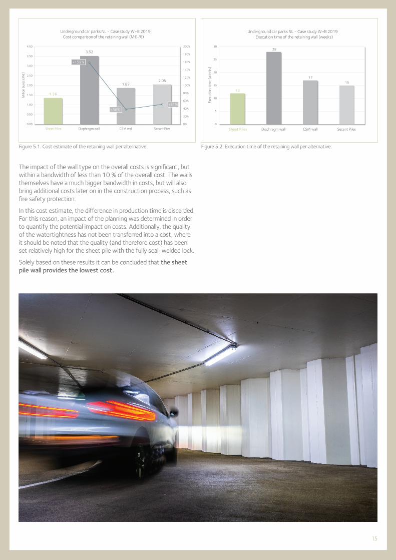
The impact of the wall type on the overall costs is significant, but within a bandwidth of less than 10 % of the overall cost. The walls themselves have a much bigger bandwidth in costs, but will also bring additional costs later on in the construction process, such as fire safety protection.
In this cost estimate, the difference in production time is discarded. For this reason, an impact of the planning was determined in order to quantify the potential impact on costs. Additionally, the quality of the watertightness has not been transferred into a cost, where it should be noted that the quality (and therefore cost) has been set relatively high for the sheet pile with the fully seal-welded lock.
Solely based on these results it can be concluded that the sheet pile wall provides the lowest cost.
Figure 5.1. Cost estimate of the retaining wall per alternative. Figure 5.2. Execution time of the retaining wall per alternative.

16
6. Impact of wall type on planning and cashflow
Although in normal production various construction steps will be aligned and combined, the retaining wall does not allow much combination and will always remain on the critical path as a separate sequential construction step. The production speed has therefore a direct correlation with total construction time and cash flow.
For this reason, the production speeds and related preparations have been compared, based on a width of 30 m by a length of 250 m, total circumference of 560 m. Furthermore, the analysis assumes 5 working days per week.
Sheet piles: installation with the pressed-in method at a rate of 10 m of wall per day, and three additional days for primary equipment and materials. This implies 56 days of production and three days preparation. Total time spent 59 days, almost 12 weeks. The seal-welding of the sheet piles interlocks will be a parallel part of construction and therefore has no impact on the critical path. Besides the welding of the rebars can be prepared at a higher pace than the sheet pile installation.
D-Wall: production of 1 panel per day, with one crane on site, and 5 m width. This implies 112 days of production. Mobilization of the crane and bentonite facility will require 2 weeks, supporting walls will require 4 weeks in advance of production, so total 6 weeks (30 working days) prior to production. Total time spent 142 days, well beyond 28 weeks.
SoilMix: production of 4 panels per day, with an effective width of 2.5 m per panel, hence 10 m per day. Execution speed is identical to steel sheet piles, site preparation identical to D-Walls. This implies 56 days of production and 30 days of preparation. Total time spent 86 working days, approximately 17 weeks.
Secant pile: 16 bored piles per day lead to a production of 8 m per day, so in total 70 days of installation. Site preparation is comparable to sheet pile installation, say 3 days. Total time spent 73 days, approximately 15 weeks.
The impact of the execution time on the critical path can be transferred into cashflow. Two financial aspects will be affected due to an increase of duration of construction. The investment itself will require a longer duration, which implies that interest payments will have to be made over a longer period or over a slightly bigger sum given the equal period of lifespan and later start of payment. The revenue will also be postponed.
Item Unit Sheet Piles D-Wall CSM Secant Piles
Duration weeks 12 28 17 15
Impact critical path weeks (reference) 16 5 3
Total investment M€ 33.4 38.0 34.5 34.9
Annual investment cost: 3% € 0 350 769 99 519 60 404
Loss of income* € 0 1 008 000 15 000 189 000
Total increase of required cash € 0 1 358 769 414 519 249 404
Total overall cost M€ 33.4 39.4 34.9 35.1
* Assuming 105 € per parking space per week.
Table 6.1. Overview cashflow consequences of delay at critical path.

17
7. Summary
*ULS **SLS
The objective of the analysis was to work out a sound comparison of several alternative solutions to build a retaining wall for an underground car park in an urban area. W+B carried out a simple but realistic case study, assuming a standard geometry of approximately 30 m by 250 m, providing approximately 600 parking spaces, situated in an inner-city environment with concerns on settlement and vibration. The subsoil is typical for deltaic areas and with a relatively shallow groundwater table.
In terms of risks it should be noted that watertightness is a serious concern in deltaic soil conditions for secant pile walls as well as for SoilMix wall types.
Wall type L[m]
Md
[kNm/m]MR,d
[kNm/m]U.C.[-]
f[mm]
fmax
[mm]U.C.[-]
AZ 20-700 14.0 335 511 * 0.65 21.3 50 0.43
D-Wall - 800 14.0 502 *
334 **1 086 *
450 **0.460.74 6.2 50 0.13
SoilMix - 550 15.0 327 477 * 0.69 20.1 50 0.40
Secant pile - ø 630 15.0 414 525 * 0.79 9.5 50 0.19
Item Unit Sheet Piles D-Wall CSM Secant Piles
Wall type M€ 1.36 3.52 1.87 2.05
Total investment costs M€ 33.4 38.0 34.5 34.9
One parking space € 55 730 63 292 57 527 58 163
Table 7.1. Overview unity check per alternative.
Table 7.2. Overview total cost estimate per alternative.
The wall types steel sheet piles and SoilMix must be equipped with fire protection measures in order to comply with fire safety regulations. The sheet pile is considered to be covered with a sprayed protection and the SoilMix wall with a plated version, both with a typical thickness set at 30 mm.
Cost estimates and installation estimates allow to compare the overall cost-efficiency of each alternative, including cost and cashflow impact.
Item Unit Sheet Piles D-Wall CSM Secant
Duration weeks 12 28 17 15
Total investment M€ 33.4 38.0 34.5 34.9
Total increase of required cash M€ 0 1.36 0.41 0.25
Total overall cost M€ 33.4 39.4 34.9 35.1
Table 7.3. Overview cashflow consequences of delay at critical path.
18
Conclusion
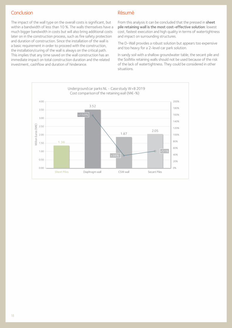
The impact of the wall type on the overall costs is significant, but within a bandwidth of less than 10 %. The walls themselves have a much bigger bandwidth in costs but will also bring additional costs later on in the construction process, such as fire safety protection and duration of construction. Since the installation of the wall is a basic requirement in order to proceed with the construction, the installation/curing of the wall is always on the critical path. This implies that any time saved on the wall construction has an immediate impact on total construction duration and the related investment, cashflow and duration of hinderance.
1.36
3.52
1.872.05
+159%
+38%+51%
0%
20%
40%
60%
80%
100%
120%
140%
160%
180%
200%
Sheet Piles Diaphragm wall CSM wall Secant Piles0.00
0.50
1.00
1.50
2.00
2.50
3.00
3.50
4.00
Milli
on E
uros
(M
€)
Cost comparison of the retaining wall (M€-%) Underground car parks NL - Case study W+B 2019
Résumé
From this analysis it can be concluded that the pressed in sheet pile retaining wall is the most cost-effective solution: lowest cost, fastest execution and high quality in terms of watertightness and impact on surrounding structures.
The D-Wall provides a robust solution but appears too expensive and too heavy for a 2-level car park solution.
In sandy soil with a shallow groundwater table, the secant pile and the SoilMix retaining walls should not be used because of the risk of the lack of watertightness. They could be considered in other situations.

19
8. References
Unpublished reports prepared for ArcelorMittal
[a] Steel Sheet Piles for Underground Car Parks (UCP), Royal Haskoning DHV NL, the Netherlands, 2018;
[b] Underground Car Parks Design, Witteveen + Bos, the Netherlands, 2020.
Dutch standards, recommendations and guidelines used in the design analysis by Witteveen + Bos
[1] Bouwbesluit 2012, besluit van 29 augustus 2011 houdende vaststelling van voorschriften met betrekking tot het bouwen, gebruiken en slopen van bouwwerken, Staatsblad van het Koninkrijk der Nederlanden 416, jaargang 2011;
[2] NEN 6098, rookbeheersingssystemen voor mechanisch geventileerde parkeergarages, Nederlands Normalisatie Instituut, February 2012;
[3] NEN-EN 1990+A1+A1/C2, Eurocode: Grondslagen van het constructief ontwerp, Nederlands Normalisatie Instituut, December 2011;
[4] NEN-EN 1991-1-2+C1, Eurocode 1: Belastingen op constructies - Deel 1-2: Algemene belastingen - Belasting bij brand, Nederlands Normalisatie Instituut, December 2011;
[5] NEN-EN 1992-1-2+C1, Eurocode 2: Ontwerp en berekening van betonconstructies - Deel 1-2: Algemene regels - Ontwerp en berekening van constructies bij brand, Nederlands Normalisatie Instituut, November 2011;
[6] NEN-EN 1993-1-2+C2, Eurocode 3: Ontwerp en berekening van staalconstructies - Deel 1-2: Algemene regels - Ontwerp en berekening van constructies bij brand, Nederlands Normalisatie Instituut, December 2011;
[7] ROK, Richtlijnen Ontwerp Kunstwerken, versie 1.4, Rijkswaterstaat, April 2017;
[8] Demonstration of real fire tests in car parks and high buildings, rapport EUR 20466 EN, Contract No. 7215-PP/025, European Commission, technical steel research, steel structures, 2002;
[9] Onderzoek brand parkeergarage Lloydstraat, Rotterdam, Efectis Nederland rapport 2007-Efectis- R0894, opdrachtgever: Veiligheidsregio Rotterdam-Rijnmond, Efectis, December 2007;
[10] NEN-EN 1993-5:2008 en, Eurocode 3: Ontwerp en berekening van staalconstructies - Deel 5: Palen en damwanden, Nederlands Normalisatie Instituut, February 2008;
[11] NEN-EN 1993-5:2008/NB:2012 en, Nationale bijlage bij Eurocode 3: Ontwerp en berekening van staalconstructies - Deel 5: Palen en damwanden, Nederlands Normalisatie Instituut, May 2012;
[12] NEN-EN 1997-1+C1+A1:2016/NB:2019 nl, Nationale bijlage bij NEN-EN 1997-1 Eurocode 7: Geotechnisch ontwerp - Deel 1: Algemene regels, Nederlands Normalisatie Instituut, July 2019.

20
Edition 6.2021
Printed on FSC paper. The FSC label certifies that the wood comes from forests or plantations that are managed in a responsible and sustainable way (the FSC principles promote the social, economical, environmental and cultural needs of today’s and the next generations). www.fsc.org
Disclaimer
The data and commentary contained within this steel sheet piling document is for general information purposes only. It is provided withoutwarranty of any kind. ArcelorMittal Commercial RPS S.à r.l. shall not be held responsible for any errors, omissions or misuse of any of the enclosedinformation and hereby disclaims any and all liability resulting from the ability or inability to use the information contained within.Anyone making use of this material does so at his/her own risk. In no event will ArcelorMittal Commercial RPS S.à r.l. be held liable for anydamages including lost profits, lost savings or other incidental or consequential damages arising from use of or inability to use the informationcontained within. Our sheet pile range is liable to change without notice.


ArcelorMittal Commercial RPS S.à r.l.Sheet Piling
66, rue de LuxembourgL-4221 Esch-sur-Alzette (Luxembourg)
ArcelorMittalSP
Hotline: (+352) 5313 3105
ArcelorMittal Sheet Piling (group)
UC
P W
+B-
EN


![Detailed Design - Encsusers.encs.concordia.ca/~gregb/home/PDF/soen6461_detailed_desig… · Detailed Design Detailed Design De nition [ISO/IEC 24765] 1. the process of re ning and](https://static.documents.pub/doc/80x56/5fc1b7136dc1b844fc30e737/detailed-design-gregbhomepdfsoen6461detaileddesig-detailed-design-detailed.jpg)


