DETAILS OF BEAM DIAGNOSTIC SYSTEM FOR RIKEN SUPERCONDUCTING RING CYCLOTRON K. Yamada ∗ , M. Fujimaki, N. Fukunishi, A. Goto, M. Kase, M. Komiyama, J. Ohnishi, H. Okuno, T. Watanabe, and Y. Yano, RIKEN Nishina Center, Wako, Saitama 351-0198, Japan Abstract Superconducting ring cyclotron (SRC) is the main accel- erator for the RI Beam Factory project at RIKEN Nishina center, and that enables us to realize the uranium beam with energy of 345 MeV/nucleon. The SRC was successfully commissioned and the first uranium beam was extracted in March 2007. Beam diagnostic system for the SRC con- sists of seven wire monitors, four faraday cups, three radial probes, 20 pairs of phase probes, and 60 elements of baf- fle slits. Their signals were amplified and led to another room, and converted to digital signals. The digital data were read out through the Ethernet by the control system using EPICS, and displayed on PC monitors. In this report, details of the beam diagnostic system, their availability, and what to be improved are presented. INTRODUCTION RIKEN superconducting ring cyclotron (SRC) [1] is the world’s first and largest ring cyclotron using superconduct- ing sector magnet, that is the final booster for the acceler- ator complex of Radioactive Isotope Beam Factory (RIBF) at RIKEN Nishina Center [2]. The maximum sector field of 3.8T achieves the K=2600 MeV, it can accelerate any kind of heavy ions up to β = v/c =0.7. As shown in Fig. 1, beam diagnostic system for the SRC consists of the following elements: three radial probes for measuring the beam current and turn pattern at the circumference orbital region, seven wire monitors for observing the beam profile, four faraday cups for determining the total beam current, 20 channels of phase probes to search the isochronism condi- tion, and total 60 channels of baffle slits for the adjustment of injector and extractor elements. DETAILS OF EACH ELEMENT Wire Monitor For transporting the incident beam to the center of the SRC, beam trajectory have to be adjusted to negate the deviation caused by stray field at the valley region. Four horizontal-steering magnet and three vertical-steering mag- net are provided for the adjustment. To measure the beam profile, five wire monitors are mounted on the transport line for incident beam: one monitor at the upstream of the SRC, two monitors at the valley region, and two monitors at the central region of the SRC. Other two wire monitors are lo- cated at the beam line just after the extraction of the SRC ∗ [email protected]Figure 1: Entire map of beam diagnostic probes on SRC. to confirm the beam profile providing to the experiment fa- cility. Each monitor has three wires that are made of tung- sten with 0.3 mm × 3 mm section. As shown in Fig. 2, signals are amplified by a linear pre-amplifier located in the vicinity of each monitor, and connected to Network Device Interface Module (N-DIM) [3] using a low-noise multi-wire cable. Signal of potentiometer is also read out by the N-DIM. The N-DIM includes analog to digital con- verters, and digital data are collected through the Ethernet by a controller system [4] using EPICS. Figure 3 describes beam profile of 84 Kr 31+ plotted on a PC monitor. Baffle slit Log Amp. Faraday cup Wire monitor for suppressor Pre Amp. N-DIM FC N-DIM FC N-DIM PF Log Amp. Ethernet EPICS Control Potentiometer HV Differential Integral Rotary encoder Servo motor Head Pre Amp. Log Amp. N-DIM FC PLC Servo Amp. N-DIM RP Figure 2: Schematic diagram of measuring system for wire monitor, faraday cup, baffle slit, and radial probe. Cyclotrons and Their Applications 2007, Eighteenth International Conference 325
Transcript
DETAILS OF BEAM DIAGNOSTIC SYSTEM FOR RIKENSUPERCONDUCTING RING CYCLOTRON
K. Yamada∗, M. Fujimaki, N. Fukunishi, A. Goto, M. Kase, M. Komiyama, J. Ohnishi,H. Okuno, T. Watanabe, and Y. Yano, RIKEN Nishina Center, Wako, Saitama 351-0198, Japan
Abstract
Superconducting ring cyclotron (SRC) is the main accel-erator for the RI Beam Factory project at RIKEN Nishinacenter, and that enables us to realize the uranium beam withenergy of 345 MeV/nucleon. The SRC was successfullycommissioned and the first uranium beam was extracted inMarch 2007. Beam diagnostic system for the SRC con-sists of seven wire monitors, four faraday cups, three radialprobes, 20 pairs of phase probes, and 60 elements of baf-fle slits. Their signals were amplified and led to anotherroom, and converted to digital signals. The digital datawere read out through the Ethernet by the control systemusing EPICS, and displayed on PC monitors. In this report,details of the beam diagnostic system, their availability, andwhat to be improved are presented.
INTRODUCTION
RIKEN superconducting ring cyclotron (SRC) [1] is theworld’s first and largest ring cyclotron using superconduct-ing sector magnet, that is the final booster for the acceler-ator complex of Radioactive Isotope Beam Factory (RIBF)at RIKEN Nishina Center [2]. The maximum sector fieldof 3.8T achieves the K=2600 MeV, it can accelerate anykind of heavy ions up to β = v/c = 0.7. As shown inFig. 1, beam diagnostic system for the SRC consists of thefollowing elements: three radial probes for measuring thebeam current and turn pattern at the circumference orbitalregion, seven wire monitors for observing the beam profile,four faraday cups for determining the total beam current, 20channels of phase probes to search the isochronism condi-tion, and total 60 channels of baffle slits for the adjustmentof injector and extractor elements.
DETAILS OF EACH ELEMENT
Wire Monitor
For transporting the incident beam to the center of theSRC, beam trajectory have to be adjusted to negate thedeviation caused by stray field at the valley region. Fourhorizontal-steering magnet and three vertical-steering mag-net are provided for the adjustment. To measure the beamprofile, five wire monitors are mounted on the transport linefor incident beam: one monitor at the upstream of the SRC,two monitors at the valley region, and two monitors at thecentral region of the SRC. Other two wire monitors are lo-cated at the beam line just after the extraction of the SRC
Figure 1: Entire map of beam diagnostic probes on SRC.
to confirm the beam profile providing to the experiment fa-cility. Each monitor has three wires that are made of tung-sten with 0.3 mm × 3 mm section. As shown in Fig. 2,signals are amplified by a linear pre-amplifier located inthe vicinity of each monitor, and connected to NetworkDevice Interface Module (N-DIM) [3] using a low-noisemulti-wire cable. Signal of potentiometer is also read outby the N-DIM. The N-DIM includes analog to digital con-verters, and digital data are collected through the Ethernetby a controller system [4] using EPICS. Figure 3 describesbeam profile of 84Kr31+ plotted on a PC monitor.
Baffle slit
LogAmp.
Faraday cup
Wire monitor
for suppressor
PreAmp.
N-DIM FC
N-DIM FC
N-DIM PF
LogAmp.
Ethernet
EPICSControl
Potentiometer
HV
Differential
Integral
Rotaryencoder
Servomotor
Head
PreAmp.
LogAmp.
N-DIM FC
PLC ServoAmp.
N-DIM RP
Figure 2: Schematic diagram of measuring system for wiremonitor, faraday cup, baffle slit, and radial probe.
Cyclotrons and Their Applications 2007, Eighteenth International Conference
325
Figure 3: Example for data plots of wire monitors.
Faraday Cup
Total beam intensity are measured by faraday cups in-stalled at the entrance, central region, orbital region, andexit of the SRC. The cup is made of oxygen-free copperwith water cooling, and two types of secondary-electronsuppressor are used, one is a suppressor by electrostaticfield up to 1 kV, the other is a suppressor by magneticfield using a neodymium magnet. The cups of magnetic-suppressor type, which endure heat load up to 10 kW, aremounted except for the one on the orbital region. Signal isfed to logarithmic amplifiers using low-noise coaxial cableand read out by the N-DIM as described in Fig 2.
Figure 4: Monitor view of beam current (faraday cup andbaffle slits).
Baffle Slit
Baffle slits are mounted on the inlet and outlet of mag-netic deflecting channels (MIC, MDC) as listed in Table 1.Each slit is divided into four pieces, left, right, up, anddown. Some slits have the piece for orbital side. Elec-trostatic deflectors (EIC, EDC) have a slit for protectionof electrode and slits at side hole where incident beam ispassing through. The slit piece is made of tantalum platewith 5 mm thickness. Signals are connected to vacuum-feedthrough by either tantalum wires with alumina bead orfiberglass cables, and fed to relay panel by coaxial cables.
As shown in Fig. 2, the procedure of signal readout is sim-ilar to the faraday cup. Four trendlines are plotted on adisplay with the one of faraday cup simultaneously.
Table 1: Location of baffle slitsElement Position TypeSide of EDC L, R, U, D FixedSide of EIC L, R, U, D MovableInlet of MIC2 L, R, U, D FixedOutlet of MIC2 L, R, U, D FixedInlet of MIC1 L, R, U, D, Orbit FixedOutlet of MIC1 L, R, U, D, Orbit FixedInlet of EIC R FixedInlet of EDC L FixedInlet of MDC1 L, R, U, D, Orbit FixedOutlet of MDC1 L, R, U, D, Orbit FixedInlet of MDC2 L, R, U, D, Orbit FixedOutlet of MDC2 L, R, U, D, Orbit FixedInlet of MDC3 L, R, U, D FixedOutlet of MDC3 L, R, U, D FixedCenter of EBM1 L, R, U, D Movable
1bending magnet for extraction
Radial Probe
Three radial probes (MDP, ERP1, ERP2) are mounted onthe SRC. The MDP can sweep entire region from injectionto extraction, whereas the ERP1 and ERP2 can measurein the outside region. Each probe has a block for measur-ing total beam current (INTEGRAL) and three electrodesfor observing turn pattern (DIFFERENTIAL). The block ismade of oxygen-free copper with 50 mm thickness, whichis water cooled. The electrode is made of tantalum with5 mm thickness, and mounted on the back of the copperblock with 0.5 mm overhang. As shown in Fig. 5, the turn
Figure 5: MDP turn pattern. Performance is insufficientnow (see text).
pattern can be plotted on the PC monitor by three compo-nents (up, mid, down) or sum spectrum. The tips of copperblock is cut with the angle of beam trajectory evaluated
Cyclotrons and Their Applications 2007, Eighteenth International Conference
326
Table 2: Radial probe specificationsMDP ERP1 ERP2
HeadINTEG. OFC 50mm OFC 50mm OFC 50mm(Tips) 3.3 deg 10 deg 9.9 deg(Tilt) 4.5 deg fixed fixedDIFF. Ta 5 mm Ta 5mm Ta 5mm
Stroke 3050 mm 900 mm 900 mmSpeed ≤ 33 mm/s ≤ 33 mm/s ≤ 33 mm/sAccuracy 0.5 mm 0.1 mm 0.1 mm
by calculations. The head of MDP is automatically tiltedwhen it arrives in the inside region. Specifications of radialprobes are summarized in Table 2. Moving directive andsense of position are controlled by a programmable logiccontroller as shown in Fig. 2. When the execution of turnpattern measurement, signal of electrodes and encoder out-put are read out by N-DIM.
Phase Probe
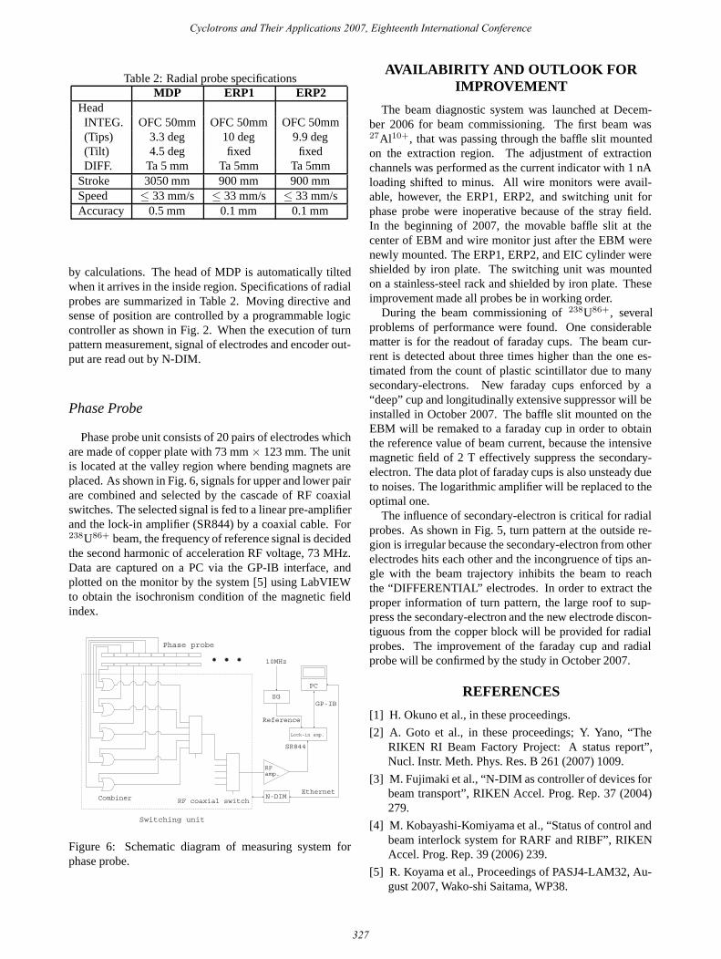
Phase probe unit consists of 20 pairs of electrodes whichare made of copper plate with 73 mm × 123 mm. The unitis located at the valley region where bending magnets areplaced. As shown in Fig. 6, signals for upper and lower pairare combined and selected by the cascade of RF coaxialswitches. The selected signal is fed to a linear pre-amplifierand the lock-in amplifier (SR844) by a coaxial cable. For238U86+ beam, the frequency of reference signal is decidedthe second harmonic of acceleration RF voltage, 73 MHz.Data are captured on a PC via the GP-IB interface, andplotted on the monitor by the system [5] using LabVIEWto obtain the isochronism condition of the magnetic fieldindex.
Combiner RF coaxial switch
Lock-in amp.
RFamp.
10MHz
SG
PC
SR844
GP-IB
Switching unit
Phase probe
N-DIMEthernet
Reference
Figure 6: Schematic diagram of measuring system forphase probe.
AVAILABIRITY AND OUTLOOK FORIMPROVEMENT
The beam diagnostic system was launched at Decem-ber 2006 for beam commissioning. The first beam was27Al10+, that was passing through the baffle slit mountedon the extraction region. The adjustment of extractionchannels was performed as the current indicator with 1 nAloading shifted to minus. All wire monitors were avail-able, however, the ERP1, ERP2, and switching unit forphase probe were inoperative because of the stray field.In the beginning of 2007, the movable baffle slit at thecenter of EBM and wire monitor just after the EBM werenewly mounted. The ERP1, ERP2, and EIC cylinder wereshielded by iron plate. The switching unit was mountedon a stainless-steel rack and shielded by iron plate. Theseimprovement made all probes be in working order.
During the beam commissioning of 238U86+, severalproblems of performance were found. One considerablematter is for the readout of faraday cups. The beam cur-rent is detected about three times higher than the one es-timated from the count of plastic scintillator due to manysecondary-electrons. New faraday cups enforced by a“deep” cup and longitudinally extensive suppressor will beinstalled in October 2007. The baffle slit mounted on theEBM will be remaked to a faraday cup in order to obtainthe reference value of beam current, because the intensivemagnetic field of 2 T effectively suppress the secondary-electron. The data plot of faraday cups is also unsteady dueto noises. The logarithmic amplifier will be replaced to theoptimal one.
The influence of secondary-electron is critical for radialprobes. As shown in Fig. 5, turn pattern at the outside re-gion is irregular because the secondary-electron from otherelectrodes hits each other and the incongruence of tips an-gle with the beam trajectory inhibits the beam to reachthe “DIFFERENTIAL” electrodes. In order to extract theproper information of turn pattern, the large roof to sup-press the secondary-electron and the new electrode discon-tiguous from the copper block will be provided for radialprobes. The improvement of the faraday cup and radialprobe will be confirmed by the study in October 2007.
REFERENCES
[1] H. Okuno et al., in these proceedings.
[2] A. Goto et al., in these proceedings; Y. Yano, “TheRIKEN RI Beam Factory Project: A status report”,Nucl. Instr. Meth. Phys. Res. B 261 (2007) 1009.
[3] M. Fujimaki et al., “N-DIM as controller of devices forbeam transport”, RIKEN Accel. Prog. Rep. 37 (2004)279.
[4] M. Kobayashi-Komiyama et al., “Status of control andbeam interlock system for RARF and RIBF”, RIKENAccel. Prog. Rep. 39 (2006) 239.
[5] R. Koyama et al., Proceedings of PASJ4-LAM32, Au-gust 2007, Wako-shi Saitama, WP38.
Cyclotrons and Their Applications 2007, Eighteenth International Conference


![Status of RIBF Accelerators at RIKENaccelconf.web.cern.ch/accelconf/Cyclotrons2010/papers/tum2cio01.pdfsynthesis. INTRODUCTION The Radioactive Isotope Beam Factory (RIBF)[1] at RIKEN](https://static.documents.pub/doc/80x56/5e6cd251d2074b05ef0d5efc/status-of-ribf-accelerators-at-synthesis-introduction-the-radioactive-isotope-beam.jpg)


