24
DT 14-E DETAN ROD SYSTEMS FAÇADE

DT 14-EDETAN ROD SYSTEMS
FAÇADE

DETAN ROD SYSTEMS
© 2014 HALFEN · DT 14-E · www.halfen.com
DETAN — a Creative Design Element
Project:Manchester CivilJustice Centre, UK
In this project DETAN was purposely applied as a visual, creative design element.
The effect is an elegant, aesthetic structure.
DETAN fits perfectly into the architectural concept and significantly contributes to the overall style.
2

DETAN ROD SYSTEMS
© 2014 HALFEN · DT 14-E · www.halfen.com
DETAN — a Static Element with Aesthetical Claim
Project:The Sage, Gateshead
Cross bracings provide a futuristic, lightweight construction.
For structural reasons, DETAN runs diagonally through the glazed façade.
The delicate DETAN system is perfectly integrated, emphasizing the fascinating overall impression of the building.
3

DETAN ROD SYSTEMS
© 2014 HALFEN · DT 14-E · www.halfen.com
The Advantages at a Glance
ETA-European Technical Approval — a secure base for structural design
New approval for DETAN-E • tension rod system DETAN-E in stainless steel now with European Technical
Approval ETA-11/0311 • an additional type-test report based on the ETA approval and Eurocode 3
allows a straightforward application of design values from tables • permanent quality and production monitoring by a supervisory institution • CE-certifi cation recognized in all European Union countries
• 25% higher load capacity due to the rod's tension capacity • tension rods are fully loadable (no reduction factor for single system sizes has to be considered)• design of allowable loads considering country-specifi c coeffi ciants M1 and M2 (NAD) with the new DETAN software• minimum requirements (strength class 235) to building-site connection plates simplify supply• EU wide standardised design concept• no requirement for national approvals or certifi cates• cross couplers are now available in stainless steel• cross couplers are a cost eff ective alternative to anchor discs for cross bracings
Design of compression rods • dimensioning of DETAN-E compression rods in stainless steel strength class
235 acccording to general certifi cate of approval Z-30.3-6 • dimensioning of DETAN-E compression rods in stainless steel strength class
235, acccording to Eurocode 3 (EN1993-1-4)
Approval for DETAN-S460 • tension rod system DETAN-S460 with European Technical Approval ETA-05/0207 • an additional type-test report based on the ETA approval and Eurocode 3
allows a straightforward application of design values from tables • CE-certifi cation recognized in all European Union countries • tension rods are fully loadable (no reduction factor for single system
sizes has to be considered) • design of allowable loads considering country-specifi c coeffi ciants M1 and M2
(NAD) with the new DETAN software • EU wide standardised design concept • no requirement for national approvals or certifi cates • cross couplers are a cost eff ective alternative to anchor discs for cross bracing
Design of compression rods • dimensioning of DETAN-S compression rods from tube material, strength class
S355, according to Eurocode 3 (EN1993-1-1)
NEW!
DETAN-E• European Technical Approval
ETA-11/0311• CE-certifi cation• type-test report S-WUE/120315
according to EC3
DETAN-S460• European Technical Approval
ETA-05/0207• CE-certifi cation• type-test report S-WUE/060382
according to EC3
DETAN approvals and type test reports available on the internet: www.halfen.com • Products • Tension rod system • DETAN Rod System • Product information
4

DETAN ROD SYSTEMS
© 2014 HALFEN · DT 14-E · www.halfen.com
The RAL Quality Mark is awarded by the Association for façade fi xing technology exclusively to companies that fulfi l the high standards required for “quality and test specifi cations for façade fi xing technologies”.Independent, biannual monitoring provided by specialists at Germanischer Lloyd guarantee that the importance of products, quality and the associated service are observed.
Included in the quality analysis are; specifi cations, quality management, logistics, competent technical advice, high-quality technical documentation and software, guarantee benefi ts and tender documents.
Economic and time saving
• no further assembly required on site• no danger of mix-ups• pre-assembled to system length
L + oj• free movement of threads ensured• online forms available for tender re-
quest or order → pages 21 - 22
The DETAN Rod systems up to and including 60 mm diameter will be delivered pre-assembled. Longer elements will be de-assembled as required to ease transport.
Preassembled delivery
The DETAN dimensioning software: Structural calculation and planning tool in one programme.
• user-friendly programme interface• structural calculation:
tension rod system accordingto ETA-Approval, compression rod system according to EC3 and Z-30.3-6.
• selection of various materials and fi nishes• planning and ordering of individual
solutions and standards• transferring the dimension results
to piece lists, with individual items in a printed list
• current program version in German, English, French, Polish, Dutch, Czech, Italian, Spanish, Portuguese, Magyar and Slovenian available on the Internet
www.halfen.de • Service • Software / CAD • Dimensioning Software • DETAN
DETAN Dimensioning software
The Advantages at a Glance
Certified HALFEN quality
NEW!
5

DETAN ROD SYSTEMS
© 2014 HALFEN · DT 14-E · www.halfen.com
Reliable and durable
• tension rods completely hot-dip galvanized after the manufacturing process
• no danger of hydrogen embrittlement
• no fl aking zinc
• large spanner notches ensure that rod can be properly tightened
• forks and locking nutsare hot-dip galvanized
• inner threads are protected
• threads are additionally protected against humidity and contamination
• sealing-sets as standard for rods with 16 mm diameter or larger
The DETAN Rod systems off er high protection against corrosion, especially in vulnerable areas, e.g. the threads. A further improvement; the spanner notches are milled before the rods are hot-dip galvanized.
The forks and locking nuts are hot-dip galvanized to ensure top-quality dura-ble protection against corrosion as well as a good mechanical resistance.
Corrosion protection
hot-dip galvanized
hot-dip galvanized (brushed)
Threaded plug
Inner threadprotected
Seals(standard)
HALFEN Pretension unit
• optimally tuned system • extra lightweight aluminium design• works independent of electrical power• protection of the high-quality galvanized surface• functional, simple & robust• for a detailed description → pages 18-19
Simple tensioning for system diameters 30 - 60 mm
The Advantages at a Glance
6

DETAN ROD SYSTEMS
© 2014 HALFEN · DT 14-E · www.halfen.com
Label with product-specifi c data
Rod marked with system information
Simple and customer-oriented
• showing product-specifi c information, e.g. system length, system diameter etc.• easy tracking and sorting by item numbers• ideal and fast construction site logistics• on customer request: project-specifi c data, e.g. fl oor numbers or node
Mix-ups impossible
• order and customer specifi c data (order and item number, rod length, system size)
• standard for diameter 16 mm systems and larger (DETAN-S460)
HALFEN optimises building site logistics
The Advantages at a Glance
Assembly and safety notes
Further information can be found in the installation instruction INST_DT.
Prior to installation all DETAN Rod system components need to be checked for damage. Damaged components must not be used.
Fig. 1 Fig. 2a
Fig. 3a Fig. 3b
Fig. 2b
Maximum deviation: 0.5°
Forks must be correctly aligned (Fig. 1) and positioned in the same plane (Fig. 2a) to ensure that the tension system is not subjected to bending.
To ensure the rod can be installed, one fork end of the rod must be able to swing into place; this is not always possible (see fi gure 3b).An anchor disk must be used in this case; this allows correct installation (see fi gure 3a).
i
7

DETAN ROD SYSTEMS
© 2014 HALFEN · DT 14-E · www.halfen.com
HALFEN Pretension unit
The DETAN Rod system is approved for predominantly static loads only.
System Overview
Basic system:
System variants:
with couplers or couplers with lug
DETAN Tension Rod
Anchor disc for cross bracing
with cross coupler for cross bracing
DETAN Tens ion rod sys tem
DETAN Compression Rod
Cross bracing consists of one anchor disc and up to 8 basic systems
Cross bracing consists of one system variant with cross coupler and one basic system
Suspension consists of a system variant with coupler and a lug and one basic system
Cross bracing:
DETAN Compression rod system
Ordering example → page 16Load capacity, system dimensions and materials → pages 16-17
Ordering procedure →page 9Load capacity, system dimensions and materials:Steel S460 → pages 12-13Stainless steel → pages 14-15
Ordering example →page 9Load capacity, system dimensions and materials:Steel S460 → pages 12-13Stainless steel → pages 14-15
Ordering example →page 9Load capacity, system dimensions and materials:Steel S460 → pages 12-13Stainless steel → pages 14-15
Ordering example →page 11Load capacity, system dimensions and materials:Steel S460 → page 13Stainless steel → page 15
Further information→ pages 18-19
ETA- Approval
for
stainless
steel s
ystem
DETAN-E
now availa
ble:
Stainless
steel s
ystem
NEW!
NEW!
8

DETAN ROD SYSTEMS
© 2014 HALFEN · DT 14-E · www.halfen.com
System DETAN-S460, European Technical Approval ETA-05/0207
System diameter ds [mm] 10 12 16 20 24 27 30 36 42 48 52 56 60 76 85 95
Available minimum system length L [mm]
Rod hot-dip galvanized 250 310 360 440 520 560 600 700 810 940 990 1050 1160 1480 1640 1810
Available maximum system length L with one rod [mm]
Rod hot-dip galvanized 6060 6070 12080 12100 12120 12140 12140 12170 12220 12260 12270 12290 12320 15430 15480 15530
System DETAN-E, European Technical Approval ETA-11/0311
System diameter ds [mm] 6 8 10 12 16 20 24 27 30
Available minimum system length L [mm]
polished 190 210 250 310 360 440 520 560 600
Available maximum system length L with one rod [mm]
polished 3040 6050 6060 6070 6080 6100 6120 6140 6140
System length L
System diameter dS
System diameter dS
System diameter dS
Product Range Overview: DETAN Tension Rod System
Basic sys tem
Order ing procedure
Product / DETAN System/ system diameter ds / system length L / specifi cation
Ordering example (material steel hdg): Tension rod system, DETAN-S460, dS = 52 mm, L = 3620 mm fv
Sys tem var iants
with coupler:
Ordering example (material stainless steel): Tension rod system, DETAN-E, dS = 24 mm, L = 11200 mm, 2 couplers
Note: Maximum 5 couplers possible.
coupler with lug:
Ordering example (material steel hdg): Tension rod system, DETAN-S460, dS = 30 mm, L = 34000 mm fv, 3 couplers with lug
Note: Maximum 5 couplers possible. Items not delivered pre-assembled.
Tension rod system, DETAN-S460, dS = 30 mm, L = 4500 mm fv, 1 couplerExample order:
System length L
System length L
Abbreviations:wb = mill finishhdg = fv = hot-dip galvanized
9

L1 = 12000 mm L2 = 800 mm L3 = 850 mm L4 = 12000 mm
L = 25650 mm
L =
1050
mm
ds = 24 mm
ds = 10 mm
DETAN ROD SYSTEMS
© 2014 HALFEN · DT 14-E · www.halfen.com
System DETAN-S460, European Technical Approval ETA-05/0207
System diameter ds [mm] 16 20 24 27 30 36
Available minimum system length L [mm]
Rod (fv or wb) 1100 1200 1400
System DETAN-E, European Technical Approval ETA-11/0311
System diameter ds [mm] 16 20 24 27 30
Available minimum system length L [mm]
Rod (fv or wb) 1100 1200
System diameter dS
Product Range Overview: DETAN Tension Rod System
Sys tem var iants
System variant with asymmetric distribution of couplers
Order with specifi cation of system length L:
HALFEN calculates the rod lengths and minimum and maximum system length. The couplers are distributed symmetrically. If an asymmetric distribution of the couplers is required, a drawing with all necessary measurements must be included; alternatively place the order using the HALFEN dimensioning software, see page 5.
Note: Maximum 2 cross couplers possible. Items not delivered pre-assembled.
with cross coupler for cross bracing:
Ordering example (material steel hdg): Tension rod system, DETAN-S460, dS = 30 mm, L = 5600 mm fv, 1 cross coupler
Ordering example: Tension Rod System, DETAN-S460, dS = 24 mm, system length according to drawing, wb, couplers according to drawing Tension Rod System, DETAN-S460, dS = 10 mm, system length L = 1050 mm wb
A drawing with system dimensions is suffi cient.HALFEN will detail complex rod systems as one confi gured system.
System length L
Abbreviations: wb = mill finish, hdg = fv = hot-dip galvanized
10

α
α
β
DETAN ROD SYSTEMS
© 2014 HALFEN · DT 14-E · www.halfen.com
System DETAN-S460, European Technical Approval ETA-05/0207
System diameter ds [mm] 10 12 16 20 24 27 30 36 42 48 52 56 60 76 85 95
System DETAN-E, European Technical Approval ETA-11/0311
System diameter ds [mm] 6 8 10 12 16 20 24 27 30
Syste
m-diam
. dS
Syste
m-diam
. dS
Width W [mm]
Hei
ght
H [
mm
]
Width W [mm]
Hei
ght
H [
mm
]
Product Range Overview: Cross Bracings, DETAN Compression Rod System
Cross brac ing
1. Ordering example (material steel): Anchor disc, DETAN-S460, dS = 42 mm, 4 holes drilled α = 40°, β = 140° (see drawing), fv
Anchor disc
2. Ordering example (material stainless steel): Anchor disc, DETAN-E, dS = 24 mm, 8 holes drilled α = 45° (see drawing)
Note:• maximum of 8 tension rod
connections possible• connecting angle α min = 40°
Alternatively, please enquiries for complete systems with bracings as cross couplers or as anchor disks. A drawing with system dimensions is suffi cient.
2. Ordering example: Tension rod, DETAN-E, dS = 10 mm, L = 500 mm, thread length left = 120 mm, thread length right = 150 mm1. Ordering example: Connection set, DETAN-S460, dS = 20 mm, left-hand thread, fv
Set articles and individual components
• Tension rod (specify rod length separately) • Pin
• Fork connection set: Fork, locking nuts, pins, circlips, sealing kit , left-hand thread
• Locking nut, left-hand thread
• Locking nut, right-hand thread
• Fork connection set: Fork, locking nuts, pins, circlips, sealing kit , right-hand thread
• Flat seal
• Round seal
• Coupler set: coupler + 2 locking nuts, sealing kit
• Circlip for one fork
• Coupler set with lug: coupler with lug + 2 locking nuts, sealing kit
• Coupler, with lug
• Coupler, without lug
• Cross coupler set: cross coupler + 2 locking nuts, sealing kit
• Fork, left-hand thread
• Fork, right-hand thread
• Spanner • Cross coupler
Stainless steel without sealing kitType tests and certification are only valid when using components in a complete systemMaterials, designs and dimensions refer to → p. 10 - 14
11

DETAN ROD SYSTEMS
© 2014 HALFEN · DT 14-E · www.halfen.com
System load capacities; system- and available rod lengths; material specification, steel strength grade S355 (diameter ds 10-12) or S460N
System diameter ds [mm] 10 12 16 20 24 27 30 36 42 48 52 56 60 76 85 95
System load capacities
Load capacity NR,d [kN] 21.3 30.94 70.5 110.2 158.6 206.7 252.3 367.5 504.4 662.9 791.0 913.5 1063 1750 2227 2823
Available minimum system length L [mm]
black, h.d. galvanized 250 310 360 440 520 560 600 700 810 940 990 1050 1160 1480 1640 1810
Available maximum system length with one rod [mm]
black, h.d. galvanized 6060 6070 12080 12100 12120 12140 12140 12170 12220 12260 12270 12290 12320 15430 15480 15530
Available maximum rod length L [mm]
black, h.d. galvanized 6000 12000 15000
The design loads in this table have been calculated according to technical approval ETA-05/0207, with M1 = 1.1 and M2 = 1.25.If other partial safety values are applicable, the load capacities have to be calculated according to technical approval ETA-05/0207, chapter 2.1.3. NR,d: Load capacity according to type test S-WUE/060382 based on technical approval ETA-05/0207 Longer system lengths L consisting of several rods with connecting couplers are possible!
System components — materials and finish
Tension rod Fork Couplers, locking nuts Anchor disc
System diameter ds [mm] 10 - 12 16 - 95 10 - 12 16 - 95 10 - 95 10 - 95
Material S355J2 S460N S355J2 G20 Mn5+QT S355J2/S235JR S355J2
Finishfv hot-dip galvanized hot-dip galvanized hot-dip galvanized hot-dip galvanized
wb mill finish hot-dip galvanized hot-dip galvanized hot-dip galvanized
System dimensions [mm], materials — see table above
System diameter ds 10 12 16 20 24 27 30 36 42 48 52 56 60 76 85 95
Fork length LDT 60 73 89 110 133 147 160 192 225 265 285 305 335 460 520 580
Pin length lB 28 32 44 52 60 65 72 84 97 111 119 130 139 180 202 229
Fork breadth p 20 24 33 40 46 51 57 68 79 90 98 107 116 146 166 189
Fork height q 26 31 41 51 61 69 75 90 105 119 125 137 146 196 216 236
Thread depth om 15.0 18.5 22.5 27.0 34.0 37.5 42.5 51.0 55.0 62.5 70.5 77.5 85.0 115 130 155
Screw adjustment range oj 5.0 6.5 7.5 8.0 11.0 12.5 12.5 14.0 15.0 17.5 20.0 22.5 25.0 39 45 60
Length locking nut M 24.5 37.0 41.0 50.0 58.0 63.0 64.0 72.0 83.0 91.0 98.0 105 112 148 165 205
Tension rodSpanner width ts hook spanner
8 10 14 18 21 24 27 32 36 41 46 50 55 90/6 90/6 155/6
Locking nuts Use soft touch pliers
hook spanner
25-28 30-32 34-36 40-42 45-50 52-55 68-75 68-75 80-90 80-90 80-90 155/8 155/8 230/10
Length locking nut r
→ see table dimensions connecting plate page 13Pin hole diameter j
Thickness conn. plate b
Delivery time on request.Corrosion protection: rod thread hot-dip galvanized. Fork threads sealed with stoppers. Also see sealing system on page 6
Fork
System DETAN-S460, European Technical Approval ETA -05/0207
System length L
12

d s
LM
om
+ jo - jo
k M
d s
LM
k M
dsa
d s
LM
d M
ds
dsk
dKMLKM
αm
in =60°-90°α min 40°
A B C
DETAN ROD SYSTEMS
© 2014 HALFEN · DT 14-E · www.halfen.com
Anchor disc: Dimensions [mm; material specification, steel strength grade S355J2, hot-dip galvanized
System diameter ds 10 12 16 20 24 27 30 36 42 48 52 56 60 76 85 95
Diameter of circ. hole f 90 110 140 180 210 240 260 310 360 420 450 490 520 702 777 832
Outer anchor disc - diam. g 120 146 186 238 280 318 346 412 480 558 600 652 692 960 1075 1150
Dimensions [mm]; material specification, steel strength grade S355J2, hot-dip galvanized
System diameter ds 10 12 16 20 24 27 30 36 42 48 52 56 60 76 85 95
Coupler length LM 40 50 62 78 94 104 120 140 158 180 195 210 245 328 370 450
Coupler diameter dM 20 22 28 35 42 47 53 64 75 87 93 98 104 155 180 195
Thread depth om 15.0 18.5 22.5 27.0 34.0 37.5 42.5 51.0 55.0 62.5 70.5 77.5 85.0 115 130 155
Screw adjustment range oj 5.0 6.5 7.5 8.0 11.0 12.5 12.5 14.0 15.0 17.5 20.0 22.5 25.0 39 45 60
Suspension system diam. dsa - 10 10 10 10 10 10 10 10 12 12 12 12 12 16 16
Dist. of suspension hole km - 28.0 31.0 44.5 48.0 50.5 57.5 72.0 86.5 98.5 111.5 124.5 137.0 140.0 150.0 157.5
Hook spanner size - - - - - - - - - - - - - 155/8 230/10 230/10
Dimensions [mm]; Material — minimum qualities for diameter 10 - 12, steel strength grade S235JR; or for diameter 16 - 95, steel strength grade S355J2
System diameter ds 10 12 16 20 24 27 30 36 42 48 52 56 60 76 85 95
Thickness conn. plate b 8 10 15 18 20 22 25 30 35 40 45 50 55 65 75 85
Hole diameter for pin j 9.5 11.5 15.5 19.5 23.5 26.5 29.5 33.5 41 47 49 53 57 76 86 96
Hole position r 15 18 24 29 35 39 43 51 60 70 76 83 88 129 149 159
Minimum width s 28 33 40 51 64 73 80 94 113 129 142 151 161 216 240 270
Cross coupler: Dimensions [mm]; material specification, steel strength grade S355J2, hot-dip galvanized
System diameter ds 16 20 24 27 30 36
Coupler length LKM 142 166 200 222 242 284
Coupler diameter dKM 32 39 46 52 57 70
Diameter of cross rod dsk 16 20 24 27 30 36
System DETAN-S460, European Technical Approval ETA -05/0207
The dimensions specifi ed in the table below must be complied with. Plates are not included in the scope of delivery. The specifi cations also apply to the Compression rod system.
Cross bracing
Example: Anchor disc with 4 tension rods(max. of 8 rod connections per disc)
Connecting plates
Couplers
Examples:
Option 1: Anchor disc, Standard K40 (smallest connecting angle α min = 40°)
Option 2: Cross coupler(connecting angle α = 60°-90°)
Note: Coupler with lug only with system diameter 12 mm and higher.
approx. 4.2 r
≈. 2
.5 r
diam. j
diam
. fdi
am. g
b
45°only!
Note: A can only be used when simultaneously using the circular anchor disc at 45°, see page 7!
13

DETAN ROD SYSTEMS
© 2014 HALFEN · DT 14-E · www.halfen.com
System dimensions [mm]; materials, see table above
System diameter ds 6 8 10 12 16 20 24 27 30
Fork length LDT 42 50 60 73 89 110 133 147 160
Pin length lB 18 22 28 32 42 50 58 63 70
Fork breadth p 12 16 21 24 33 40 46 51 57
Fork height q 17 21 26 31 41 51 61 69 75
Thread depth om 10.5 12.5 15.0 18.5 22.5 27.0 34.0 37.5 42.5
Screw adjustment range oj 4.5 4.5 5.0 6.5 7.5 8.0 11.0 12.5 12.5
Length locking nut M 17.5 20.0 24.5 37.0 41.0 50.0 58.0 63.0 64.0
Tension rod assembly:spanner width ts 5 6 8 10 14 18 21 24 27
Locking nut assembly:hook spanner size Use soft-touch pliers 25 - 28 30 - 32 34 - 36 40 - 42 45 - 50
Edge distance r
→ see table dimensions connecting plate on page 13Pin hole diameter j
Thickness conn. plate b
System components — material and design
Tension rod Fork Couplers , locking nuts Pins , circlips Anchor disc
System diameter ds [mm] 6 - 30 6 - 30 6 - 30 6 - 30 6 - 30
Material Stainless steel Stainless steel Stainless steel Stainless steel Stainless steel
Finish A4 p polished polished polished polished polished
circlips according to DIN 471, stainless steel 1.4568 material stainless steel, strength grade S460
material stainless steel, strength grade S355material stainless steel, strength grade S235
Stainless steel acc. to ETA 11/0311, Annex 2 is conform to corrosion resistance class III of approval Z-30.3-6.
System DETAN-E in Stainless Steel, European Technical Approval ETA -11/0311
Fork
Note: The design engineer is responsible for establishing the effect of corrosion for various ambient conditions for each individual case when using DETAN-E.
System length L
System load capacities; system- and available rod length; material, stainless steel
System diameter ds [mm] 6 8 10 12 16 20 24 27 30
System load capacities
Load capacity NRd [kN] 9.42 17.13 27.14 39.44 73.32 114.6 165.0 215.0 262.4
Available minimum system length L [mm]
polished 190 210 250 310 360 440 520 560 600
Available maximum system length with one rod [mm]
polished 3040 6050 6060 6070 6080 6100 6120 6140 6140
Available maximum rod length L [mm]
polished 3000 6000
The partial safety value for above table has been calculated with M1 = 1.1 and M2 = 1.25 according to ETA-11/0311If other partial safety values apply the load capacities have to be calculated. NRd: Load capacity according to type test report S-WUE/120315 DETAN-E in accordance with ETA-Approval 11/0311 Longer system lengths L consisting of several rods with connecting couplers are possible!
14

d s
LM
om
+ jo - jo
k M
d s
LM
k M
dsa
d s
LM
d M
ds
dsk
dKMLKM
αm
in =60°-90°
A B C
45°only!
α min 40°
DETAN ROD SYSTEMS
© 2014 HALFEN · DT 14-E · www.halfen.com
System DETAN-E in Stainless Steel, European Technical Approval ETA -11/0311
Dimensions [mm]; stainless steel, strength grade S355
System diameter ds 6 8 10 12 16 20 24 27 30
Coupler length LM 34 40 40 50 62 78 94 104 120
Coupler diameter dM 12 15 20 22 28 35 42 47 53
Thread depth om 10.5 12.5 15.0 18.5 22.5 27.0 34.0 37.5 42.5
Screw adjustment range oj 4.5 4.5 5.0 6.5 7.5 8.0 11.0 12.5 12.5
Suspension system diam. dsa - - - 6 6 8 8 10 10
Offset, suspension hole km - - - 27.5 33.0 37.0 44.0 50.5 57.5
Dimensions [mm]; material — minimum qualities, 1.4401, 1.4404 or 1.4571 (stainless steel), strength grade S235
System diameter ds 6 8 10 12 16 20 24 27 30
Thickness conn. plate b 6 8 10 12 16 20 22 25 30
Hole diameter for pin j 6.5 7.5 9.5 11.5 14.5 18.5 21.5 24.5 26.5
Hole position r 9 12 15 18 24 29 35 39 43
Minimum width s 17 21 26 31 41 51 61 69 75
Couplers
approx. 4.2 r
≈ 2.
5 r
Cross bracingOption 1: Anchor disc, Standard K40 (smallest connecting angle α min = 40°)Example: Anchor disc with 4 tension rods(maximum of 8 rod connections per disc)
Option 2: Cross coupler(connecting angle α = 60°-90°)
Anchor disc measurements [mm]; stainless steel, strength grade S235
System diameter ds 6 8 10 12 16 20 24 27 30
Diameter of circ. hole f 55 75 90 110 140 180 210 240 260
Outer Anchor disc - diam. g 73 99 120 146 186 238 280 318 346
Cross coupler measurements [mm]; stainless steel, strength grade S355
System diameter ds 16 20 24 27 30
Coupler length LKM 142 166 200 222 242
Coupler diameter dKM 32 39 46 52 57
Diameter of cross rod dsk 16 20 24 27 30
diam. j
diam
. fdi
am. g
b
The dimensions specifi ed in the table below must be complied with. Plates are not included in the scope of delivery. The specifi cations also apply to the compression rod system.
Connecting plates Examples:
Note: A can only be used when simultaneously using the circular anchor disc at 45°, see page 7!
15

DETAN ROD SYSTEMS
© 2014 HALFEN · DT 14-E · www.halfen.com
System components and materials
Product Range Overview: DETAN Compression Rod System
System components — material and design
System diameter Ds [mm]
Compression rod Fork Locking nut
42 - 114 according to statics calculations according to statics calculations
Material S355J2 G20 Mn5+QT S235JR
Finishfv hot-dip galvanized hot-dip galvanized hot-dip galvanized
wb mill finish hot-dip galvanized hot-dip galvanized
Note: DETAN-E System on request. The planner is responsible for establishing the effect of corrosion in various ambient conditions for each individual casewhen using DETAN-E.
All fork and connecting plates system dimensions see page 12-13
Compression rod system diameter DS
System length L
Fork system diameter dS
System DETAN-S355
Compression Rod diam. Ds 42 54 60 76 89 114
Fork connector diam. ds according to structural calculations see page 17
Minimum available system length L [mm]
hot-dip galvanized 1000
Standard in stock maximum system length L for a standard-tube [mm]
hot-dip galvanized 6340 6380 6440 6540 6610 6710
Materials and designs of all components plus custom designs see table below
Ordering example: Compression rod system, DETAN-S355, Ds = 42 mm, L = 2000 mm, fork connector ds = 16 mm
To complement the DETAN Tension rod system HALFEN also off ers compression rods which can be incorporated technically and optically perfectly into a system. Compression rods consist of large diameter tubes, which are tapered at each end allowing standard DETAN Fork connectors to be used.
Note: System DETAN-E on request. Items not delivered pre-assembled.
Compress ion rod
System diameter DSSystem diameter dS
System length L
16
DETAN ROD SYSTEMS
© 2014 HALFEN · DT 14-E · www.halfen.com
System and standard lengths [mm]; material, steel strength grade S355
System diameter Ds [mm] 42 54 60 76 89 114
Tube diameter 42.4 54.0 60.3 76.1 88.9 114.3
Section thickness 2.6 2.6 2.9 2.9 3.2 3.6
max. system lengths L [mm] without reduction of load capacity Nb.R,d [KN] according to EC3: selected examples
Load capacity Nb.R,d [kN]
Fork end diam. ds [mm] max. system length L [mm]
26 16 2000 3000 3700 5400 - -
43 20 1500 2200 2800 4100 5600 -
61 24 1200 1800 2300 3400 4600 -
84 27 800 1400 1900 2800 3900 6200
106 30 - 1100 1600 2400 3400 5400
160 36 - - - 1700 2600 4300
223 42 - - - - 1800 3400
The design loads given in the table above have been calculated according to EC3 with the partial safety values M1 = 1.1 and M2 = 1.25. If other partial safety values or standards apply the load capacities have to be calculated accordingly. For design and structural calculation see HALFEN software onpage 5 and www.halfen.de.Alternatively please send a request with drawing, system dimensions and load calculation.
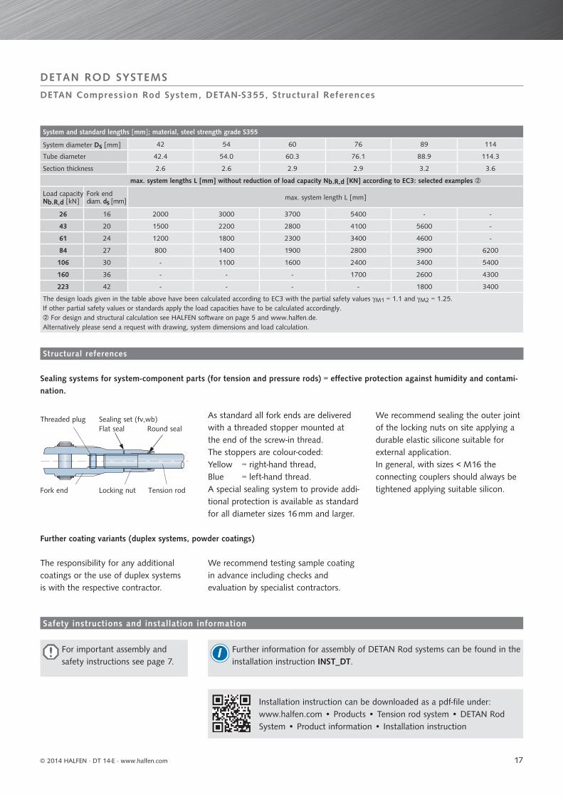
Sealing systems for system-component parts (for tension and pressure rods) = eff ective protection against humidity and contami-nation.
Further coating variants (duplex systems, powder coatings)
Safety instructions and installation information
Structural references
DETAN Compression Rod System, DETAN-S355, Structural References
Threaded plug Sealing set (fv,wb) Flat seal Round seal
Fork end Locking nut Tension rod
As standard all fork ends are delivered with a threaded stopper mounted at the end of the screw-in thread.The stoppers are colour-coded:Yellow = right-hand thread, Blue = left-hand thread. A special sealing system to provide addi-tional protection is available as standard for all diameter sizes 16 mm and larger.
We recommend sealing the outer joint of the locking nuts on site applying a durable elastic silicone suitable for external application. In general, with sizes < M16 the connecting couplers should always be tightened applying suitable silicon.
The responsibility for any additional coatings or the use of duplex systems is with the respective contractor.
We recommend testing sample coating in advance including checks and evaluation by specialist contractors.
For important assembly and safety instructions see page 7.
Installation instruction can be downloaded as a pdf-fi le under: www.halfen.com • Products • Tension rod system • DETAN Rod System • Product information • Installation instruction
Further information for assembly of DETAN Rod systems can be found in the installation instruction INST_DT.
i
17

DETAN ROD SYSTEMS
© 2014 HALFEN · DT 14-E · www.halfen.com
DETAN Pretension Unit
DETAN Pretens ion uni t — Advantages and bas ics
The exact application of pretension for system diameters 30 and larger can be quite diffi cult, therefore additional tools like hydraulic jacks become necessary. The HALFEN Pretension unit for use with DETAN Rod systems from M30 to M60 provides an eff ective solution with load transfer using a threaded-fl ange preventing damages to the rod surface.
Applying pretension
If a pretensioned system is intended then this should be considered at the planning-stage.To apply pretension, special rental units can be obtained from our Engineering team.The necessary rod force is converted into the required hydraulic pressure and then using the DETAN Pretension unit is applied to the DETAN Rod.
Pretension check
If the rod was previously gauge marked the pretension force can be controlled using an extensometer.This system can be used during as well as after load application.This allows load control using hydraulic pressure as well as monitoring direct rod strain.Similar to the DETAN Pretension unit this device is easy to use, is robust and requires no electrical power.
Additional advantages
• the system is optimised for DETAN Rods• extra lightweight aluminium design for simple assembly• targeted hydraulic application for tension up to 425 kN• no power-source needed• the high-quality galvanized surface is protected by special
load transfer fl anges• simple control of load application with a calibrated
manometer
• additional control using optional extensometer, even after load application (if previously gauge marked)
• functional, simple & robust
18

d s
LM v
d M
M
d s
LM
om
+ jo - jo
DETAN ROD SYSTEMS
© 2014 HALFEN · DT 14-E · www.halfen.com
DETAN Pretension Unit
Assembly of the pretens ion uni t
Assembly of the pretension unit
To avoid possible damage to the rod surface load transfer is via threaded fl anges. The hydraulic-system is clipped in front and behind the coupler on the threads. The hydraulic jacks temporarily relieve the strain on the coupler, allowing it to be easily turned by hand.When reaching the desired pressure, the hydraulic unit is released and remo-ved. After release the coupler takes the load.
To ensure that the maximum recom-mended load has been reached the required hydraulic pressure is needed. Please refer to the table below.Alternatively the load can be checked using an extensometer.
A detailed assembly instruction is available on the Internet:www.halfen.de • Service • Brochures • Installation instructions • DETAN
System load capacities, system lengths and available rod lengths
System diameter ds [mm] 30 36 42 48 52 56 60
Cross section A [mm²] 707 1018 1385 1810 2124 2463 2827
Thread length o [mm] 105 118 126 139 176 188 195
Available min. system length with coupler L [mm]
1076 1244 1440 1652 1758 1866 2056
Load capacity NR,d [kN] 252.3 367.5 504.4 662.9 791.0 913.5 1063
Sys tem var iat ions
with pretension coupler:
System diameter dS
System length L
Ordering example (material steel): Tension rod system, DETAN-S460, dS = 30 mm, L = 5600 mm fv, 1 pretension coupler
Pretension coupler (all dimensions in [mm])
System diameter ds 30 36 42 48 52 56 60
Coupler length LM 120 140 158 180 195 210 245
Coupler diameter dM 53 64 75 87 93 98 104
Locking nut length Mv 99 107 118 126 158 165 172
Coupler assembly SW 46 55 65 75 80 85 90
Tension rod assemblyspanner width ts
27 32 36 41 46 50 55
Locking nut assemblyhook spanner size
45-50 52-55 68-75 68-75 80-90 80-90 80-90
Pretension table for DETAN Rod system S-460 (values are partially rounded off)
Max. rec. pretension * [kN] N 100 145 200 265 315 365 425
Hydraulic pressure [bar] p 165 240 330 435 515 600 695
Strain [‰] ε 0.68 0.69 0.69 0.70 0.71 0.71 0.72
Stress [N/mm²] σ 143 144 146 147 148 148 150
Elongation [μm /10 cm] Δl 68 69 69 70 71 71 71
* Max. recommended pretension =̂ 40% of NRd
19

DETAN ROD SYSTEMS
© 2014 HALFEN · DT 14-E · www.halfen.com
Tender specification — examples
HALFEN Tension rod system type DETAN-E made of stainless steel, corrosion resistance class III according to Z-30.3-6, or accord-ing to EN 1993-1-4: 2006, consisting of 1 fork connection right-hand thread, 1 fork connection left-hand thread, plus 1 tension rod including 2 pins, 4 circlips and 2 DT-E nuts, with European Technical Approval ETA 11/0311, type-tested, RAL RAL-GZ 996/5 quality mark approved by the Association for Façade Fixing Technology (Gütegemeinschaft Fassadenbefestigungstechnik e.V.), pre-assembled and product-specifi c-labelled tension rod system, type DETAN-E, ds , L withds = system-diameter [mm] …… ( 6 / 8 / 10 / 12 / 16 / 20 / 24 / 27 / 30)L = system-length [mm] (from bolt-axis/to bolt-axis),
or equivalent; deliver and install according to manufacturer’s instructions. Includes welding the connector fl anges according to provided engineer’s specifi cations.
HALFEN Tension rod system type DETAN-S460 made of S460, consisting of 1 fork connection right-hand thread, 1 fork connec-tion left-hand thread, plus 1 tension rod including 2 pins, 4 circlips and 2 DT-S nuts,
with European Technical Approval ETA 05/0207, type-tested, RAL RAL-GZ 996/5 quality mark approved by the Association for Façade Fixing Technology (Gütegemeinschaft Fassadenbefestigungstechnik e.V.), pre-assembled and product-specifi c-labelled tension rod system, type DETAN-S460 ds = 30, L, fvwithds = system-diameter [mm]..(10 / 12 / 16 / 20 / 24 / 27 / 30 / 36 / 42 / 48 / 52 / 56 / 60 / 76 / 85 / 95)L = system-length [mm] (from bolt-axis/to bolt-axis),F = …… (material fv /wb) for hot-dip galvanized or mill fi nished surface
completely hot-dip galvanized fi nish (alternative; mill-fi nished tension rod), or equivalent; deliver and install according to manufacturer’s instructions. Includes welding the connector fl anges according to architect’s / engineer’s specifi cations.
Planning Help
HALFEN Tension rod system DETAN-E
HALFEN Tension rod system DETAN-S460 fv
System length
System-diam. ds
System-diam. ds
System length
20

DETAN ROD SYSTEMS
© 2014 HALFEN · DT 14-E · www.halfen.com
C H E C K L I S T
DETAN Tension rod system
Product fi eld :DETAN Tension rod systems
Form no.:CHK-F-DT-001-E
Customer: Contact name: Customer address:Phone: Fax: e-mail:Project: Project address:Date: Customer No: Enquiry Estimate Order
Tension rod system
Item. No.ds
[mm]
ZEd,max
[kN]
L[mm]
Quantity Quantity
Material choice
mill fi nish
hot-dip galva-nized
Stain-less steel
Example 3 30 5600 x 2 x
Design variants:
without coupler with coupler with coupler with lug
Choice of material:
: Number of couplers in one system length: maximum tension load required if diameter is unknown
Please send the completed form to HALFEN bye-mail to [email protected] contact us for an estimate.
More order forms available at:www.halfen.de•Products•Tension rod system•Order formEasy planning with DETAN Dimensioning software, see page 5.
Planning Help
System-diam. ds
System length L
DETAN-S460 - FV (hot-dip galvanized)DETAN-S460 - WB (mill-fi nish)according to European Technical Approval ETA-05/0207 and type-test report S-WUE/060382 according to EC3
DETAN-E (Stainless steel)according to European Technical Approval ETA-11/0311 and type-test report S-WUE/120315 according to EC 3,stainless steel acc. to ETA 11/0311, Annex 2 is conform to corrosion resistance class III of approval Z-30.3-6.
21
DETAN ROD SYSTEMS
© 2014 HALFEN · DT 14-E · www.halfen.com
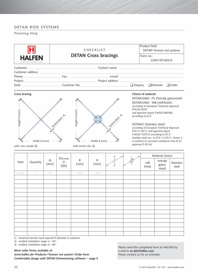
C H E C K L I S T
DETAN Cross bracings
Product fi eld:DETAN Tension rod systems
Form no.:CHK-F-DT-002-D
Cross bracing
Item Quantityds
[mm]
ZEd,max
[kN]
B[mm]
H[mm]
Material choice
mill fi nish
hot-dip galva-nized
Stainless steel
Example 3 30 5600 4200 x x
with cross coupler with anchor disc
Choice of material:DETAN-S460 - FV (hot-dip galvanized)DETAN-S460 - WB (mill-fi nish)according to European Technical Approval ETA-05/0207 and type-test report S-WUE/060382 according to EC3
DETAN-E (Stainless steel)according to European Technical Approval ETA-11/0311 and type-test report S-WUE/120315 according to EC 3,stainless steel acc. to ETA 11/0311, Annex 2 is conform to corrosion resistance class III of approval Z-30.3-6.
Hei
ght
H [
mm
]
Hei
ght
H [
mm
]
Width B [mm] Width B [mm]
Syste
m-diam
. ds
Syste
m-diam
. ds
: maximum tension load required if diameter is unknown : smallest installation angle α = 40°: smallest installation angle α = 60°
Planning Help
Customer: Contact name: Customer address:Phone: Fax: e-mail:Project: Project address:Date: Customer No: Enquiry Estimate Order
Please send this completed form to HALFEN bye-mail to [email protected] contact us for an estimate.
More order forms available at:www.halfen.de•Products•Tension rod system•Order formComfortable design with DETAN Dimensioning software → page 5
22
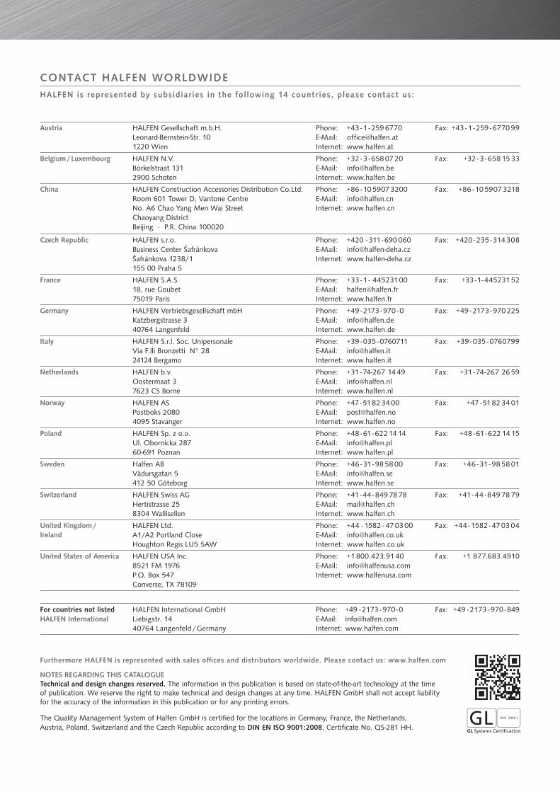
Austria HALFEN Gesellschaft m.b.H.Leonard-Bernstein-Str. 101220 Wien
Phone: +43 - 1 - 259 6770 E-Mail: [email protected]: www.halfen.at
Fax: +43 - 1 - 259 - 6770 99
Belgium / Luxembourg HALFEN N.V.Borkelstraat 1312900 Schoten
Phone: +32 - 3 - 658 07 20E-Mail: [email protected]: www.halfen.be
Fax: +32 - 3 - 658 15 33
China HALFEN Construction Accessories Distribution Co.Ltd.Room 601 Tower D, Vantone CentreNo. A6 Chao Yang Men Wai StreetChaoyang District Beijing · P.R. China 100020
Phone: +86 - 10 5907 3200E-Mail: [email protected]: www.halfen.cn
Fax: +86 - 10 5907 3218
Czech Republic HALFEN s.r.o.Business Center ŠafránkovaŠafránkova 1238/1155 00 Praha 5
Phone: +420 - 311 - 690 060E-Mail: [email protected]: www.halfen-deha.cz
Fax: +420 - 235 - 314 308
France HALFEN S.A.S.18, rue Goubet75019 Paris
Phone: +33 - 1 - 445231 00E-Mail: [email protected]: www.halfen.fr
Fax: +33 - 1 - 445231 52
Germany HALFEN Vertriebsgesellschaft mbHKatzbergstrasse 3 40764 Langenfeld
Phone: +49 - 2173 - 970 - 0E-Mail: [email protected]: www.halfen.de
Fax: +49 - 2173 - 970 225
Italy HALFEN S.r.l. Soc. UnipersonaleVia F.lli Bronzetti N° 2824124 Bergamo
Phone: +39 - 035 - 0760711E-Mail: [email protected]: www.halfen.it
Fax: +39 - 035 - 0760799
Netherlands HALFEN b.v.Oostermaat 37623 CS Borne
Phone: +31 - 74-267 14 49E-Mail: [email protected]: www.halfen.nl
Fax: +31 - 74-267 26 59
Norway HALFEN ASPostboks 20804095 Stavanger
Phone: +47 - 51 82 34 00E-Mail: [email protected]: www.halfen.no
Fax: +47 - 51 82 34 01
Poland HALFEN Sp. z o.o.Ul. Obornicka 28760-691 Poznan
Phone: +48 - 61 - 622 14 14E-Mail: [email protected]: www.halfen.pl
Fax: +48 - 61 - 622 14 15
Sweden Halfen ABVädursgatan 5412 50 Göteborg
Phone: +46 - 31 - 98 58 00E-Mail: [email protected]: www.halfen.se
Fax: +46 - 31 - 98 58 01
Switzerland HALFEN Swiss AGHertistrasse 25 8304 Wallisellen
Phone: +41 - 44 - 849 78 78E-Mail: [email protected]: www.halfen.ch
Fax: +41 - 44 - 849 78 79
United Kingdom /Ireland
HALFEN Ltd.A1/A2 Portland CloseHoughton Regis LU5 5AW
Phone: +44 - 1582 - 47 03 00E-Mail: [email protected]: www.halfen.co.uk
Fax: +44 - 1582 - 47 03 04
United States of America HALFEN USA Inc.8521 FM 1976P.O. Box 547Converse, TX 78109
Phone: +1 800.423.91 40E-Mail: [email protected]: www.halfenusa.com
Fax: +1 877.683.4910
For countries not listed HALFEN International
HALFEN International GmbHLiebigstr. 14 40764 Langenfeld / Germany
Phone: +49 - 2173 - 970 - 0 E-Mail: [email protected]: www.halfen.com
Fax: +49 - 2173 - 970 - 849
CONTACT HALFEN WORLDWIDEHALFEN is represented by subsidiaries in the following 14 countries, please contact us:
NOTES REGARDING THIS CATALOGUETechnical and design changes reserved. The information in this publication is based on state-of-the-art technology at the time of publication. We reserve the right to make technical and design changes at any time. HALFEN GmbH shall not accept liability for the accuracy of the information in this publication or for any printing errors.
The Quality Management System of Halfen GmbH is certified for the locations in Germany, France, the Netherlands, Austria, Poland, Switzerland and the Czech Republic according to DIN EN ISO 9001:2008, Certificate No. QS-281 HH.
Furthermore HALFEN is represented with sales offi ces and distributors worldwide. Please contact us: www.halfen.com

For further information please contact: www.halfen.com
© 2
014
HA
LFEN
Gm
bH, G
erm
any
appl
ies
also
to
copy
ing
in e
xtra
cts.
D -
001
- E -
06/1
4 PD
F 0
6/14


