ABSTRACT Reconfigurable structures that are enabled through the integration of multiple materials are important for future design and manufacturing practice. We investigate one of such reconfigurable structures - an origami sheet, which can be designed based on a 3D object and unfolded into a 2D sheet with complex creases. A fabrication approach based on a hybrid manufacturing process by integrating layer-based additive manufacturing and silicon molding techniques is developed. Related challenges on designing creases for given folding requirements and the related material properties are discussed. A novel structure design is presented to ensure the fabricated creases that are in soft materials can be folded and unfolded without failures. The design method can be applied to different scale levels. The origami sheets for test cases in different complexity have been tested. The experimental results illustrate that the designed and fabricated origami sheets can be folded and used for product components with reconfigurable shapes.
1 INTRODUCTION Origami is a traditional art of paper folding, in which a flat sheet of paper is transformed into a sculpture through various folding techniques. A wide variety of shapes can be made through origami such as birds, animals, flowers, boats and so on. A key of origami is the crease design on the paper sheet that correlates to the required folds. With the widely available computing power, origami fans and researchers began to develop software to automate the generation of crease design for given shapes [1, 2, 3]. For example, Cheng and Cheong [3] proposed an algorithm for constructing crease pattern of certain
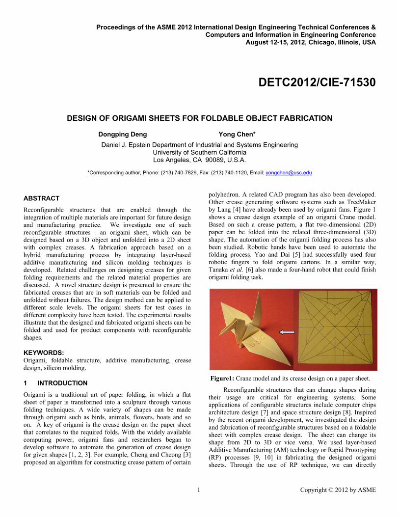
polyhedron. A related CAD program has also been developed. Other crease generating software systems such as TreeMaker by Lang [4] have already been used by origami fans. Figure 1 shows a crease design example of an origami Crane model. Based on such a crease pattern, a flat two-dimensional (2D) paper can be folded into the related three-dimensional (3D) shape. The automation of the origami folding process has also been studied. Robotic hands have been used to automate the folding process. Yao and Dai [5] had successfully used four robotic fingers to fold origami cartons. In a similar way, Tanaka et al. [6] also made a four-hand robot that could finish origami folding task.
Figure1: Crane model and its crease design on a paper sheet.
Reconfigurable structures that can change shapes during their usage are critical for engineering systems. Some applications of configurable structures include computer chips architecture design [7] and space structure design [8]. Inspired by the recent origami development, we investigated the design and fabrication of reconfigurable structures based on a foldable sheet with complex crease design. The sheet can change its shape from 2D to 3D or vice versa. We used layer-based Additive Manufacturing (AM) technology or Rapid Prototyping (RP) processes [9, 10] in fabricating the designed origami sheets. Through the use of RP technique, we can directly
2
fabricate parts with complex creases; however, the parts built by RP processes are usually made of rigid materials such as polymers, ceramics or metals. In order for the printed sheets to be foldable, soft materials are required for the designed creases that can be bended in certain angles. The use of soft materials in foldable structures has been studied extensively. Vogtmann et al [11] presented a new process for fabricating multi-material compliant mechanism for small scale robotics through laser cutting. An elastomeric material was used in the joint area, creating structures with highly tailored mechanical properties. Todoroki et al [8] used shape memory alloy wires that are embedded in a matrix material to make a partially flexible composite. In our study, we used silicone rubber, a very common yet highly flexible material [12], to make the 2D sheet foldable.
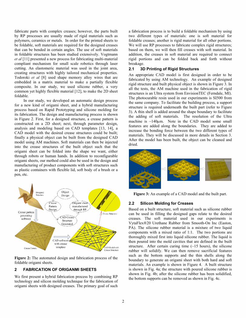
In our study, we developed an automatic design process for a new kind of origami sheet, and a hybrid manufacturing process based on Rapid Prototyping and silicone molding for its fabrication. The design and manufacturing process is shown in Figure 2. First, for a designed structure, a crease pattern is constructed on a 2D sheet; next, through parameter design, analysis and modeling based on CAD templates [13, 14], a CAD model with the desired crease structures could be built; finally a physical object can be built from the designed CAD model using AM machines. Soft materials can then be injected into the crease structures of the built object such that the origami sheet can be folded into the shape we want, either through robots or human hands. In addition to reconfigurable origami sheets, our method could also be used in the design and manufacturing of product components with soft structures such as plastic containers with flexible lid, soft body of a brush or a pen, etc.
Figure 2: The automated design and fabrication process of the foldable origami sheets.
2 FABRICATION OF ORIGANMI SHEETS We first present a hybrid fabrication process by combining RP technology and silicon molding technique for the fabrication of origami sheets with designed creases. The primary goal of such
a fabrication process is to build a foldable mechanism by using two different types of materials: one is soft material for foldable creases; another is rigid material for all other portions. We will use RP processes to fabricate complex rigid structures; based on them, we will then fill creases with soft material. In addition, the creases in soft material are required to connect rigid portions and can be folded back and forth without breakage. 2.1 3D Printing of Rigid Structures An appropriate CAD model is first designed in order to be fabricated by using AM technology. An example of designed rigid structure and built physical object is shown in Figure 3. In all the tests, the AM machine used in the fabrication of rigid structures is an Ultra system from EnvisionTEC (Ferndale, MI). The photocurable resin used in our experiments is SI500 from the same company. To facilitate the building process, a support structure is required underneath the built part (refer to Figure 3). A thin shell is added around the shape boundary to facilitate the adding of soft materials. The resolution of the Ultra machine is ~140μm. Note in the CAD model some small features are added along the boundaries. They are added to increase the bonding force between the two different types of materials. They will be discussed in more details in Section 3. After the model has been built, the object can be cleaned and dried.
Figure 3: An example of a CAD model and the built part.
2.2 Silicon Molding for Creases Based on a built structure, soft material such as silicone rubber can be used in filling the designed gaps relate to the desired creases. The soft material used in our experiments is VytaFlex®20 Urethane Rubber from Smooth-On Inc (Easton, PA). The silicone rubber material is a mixture of two liquid components with a mixed ratio of 1:1. The two portions are thoroughly mixed first into liquid silicone rubber. The liquid is then poured into the mold cavities that are defined in the built structure. After certain curing time (~15 hours), the silicone rubber will solidify. We can then remove sacrificial features such as the bottom supports and the thin shells along the boundary to generate an origami sheet with both hard and soft materials. An example is shown in Figure 4. A built structure is shown in Fig. 4a; the structure with poured silicone rubber is shown in Fig. 4b; after the silicone rubber has been solidified, the bottom supports can be removed as shown in Fig. 4c.
3
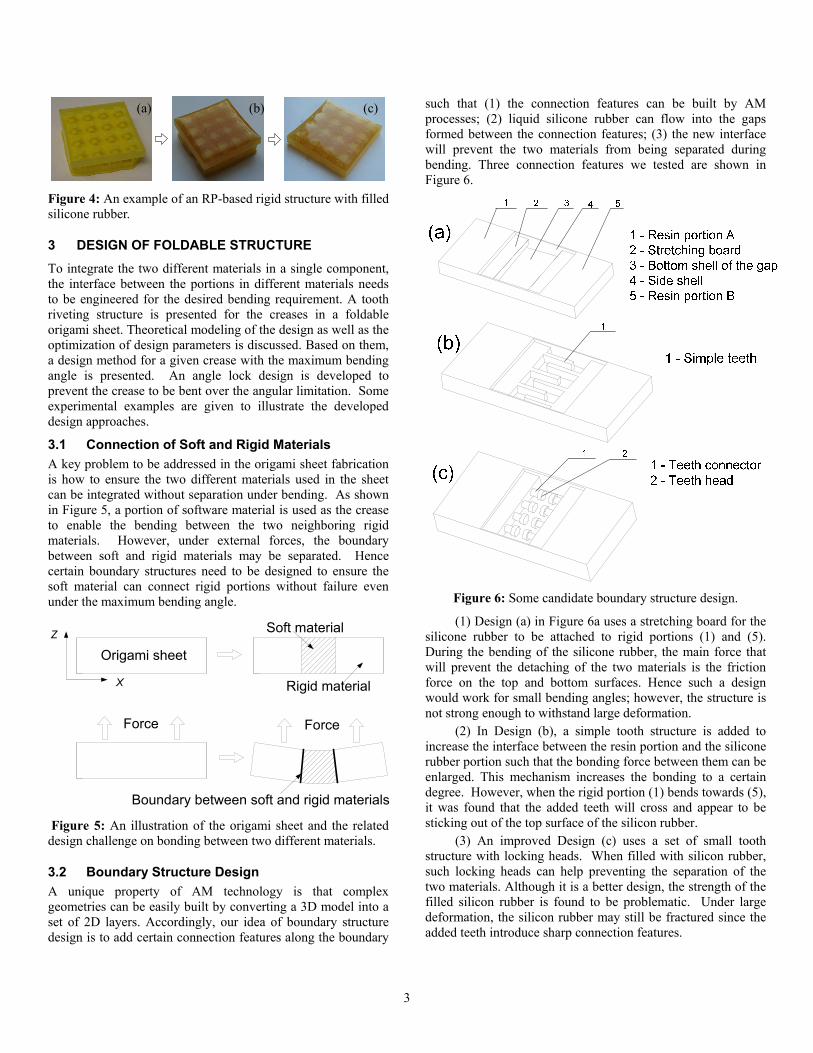
Figure 4: An example of an RP-based rigid structure with filled silicone rubber.
3 DESIGN OF FOLDABLE STRUCTURE To integrate the two different materials in a single component, the interface between the portions in different materials needs to be engineered for the desired bending requirement. A tooth riveting structure is presented for the creases in a foldable origami sheet. Theoretical modeling of the design as well as the optimization of design parameters is discussed. Based on them, a design method for a given crease with the maximum bending angle is presented. An angle lock design is developed to prevent the crease to be bent over the angular limitation. Some experimental examples are given to illustrate the developed design approaches.
3.1 Connection of Soft and Rigid Materials A key problem to be addressed in the origami sheet fabrication is how to ensure the two different materials used in the sheet can be integrated without separation under bending. As shown in Figure 5, a portion of software material is used as the crease to enable the bending between the two neighboring rigid materials. However, under external forces, the boundary between soft and rigid materials may be separated. Hence certain boundary structures need to be designed to ensure the soft material can connect rigid portions without failure even under the maximum bending angle.
Figure 5: An illustration of the origami sheet and the related design challenge on bonding between two different materials.
3.2 Boundary Structure Design A unique property of AM technology is that complex geometries can be easily built by converting a 3D model into a set of 2D layers. Accordingly, our idea of boundary structure design is to add certain connection features along the boundary
such that (1) the connection features can be built by AM processes; (2) liquid silicone rubber can flow into the gaps formed between the connection features; (3) the new interface will prevent the two materials from being separated during bending. Three connection features we tested are shown in Figure 6.
Figure 6: Some candidate boundary structure design.
(1) Design (a) in Figure 6a uses a stretching board for the silicone rubber to be attached to rigid portions (1) and (5). During the bending of the silicone rubber, the main force that will prevent the detaching of the two materials is the friction force on the top and bottom surfaces. Hence such a design would work for small bending angles; however, the structure is not strong enough to withstand large deformation.
(2) In Design (b), a simple tooth structure is added to increase the interface between the resin portion and the silicone rubber portion such that the bonding force between them can be enlarged. This mechanism increases the bonding to a certain degree. However, when the rigid portion (1) bends towards (5), it was found that the added teeth will cross and appear to be sticking out of the top surface of the silicon rubber.
(3) An improved Design (c) uses a set of small tooth structure with locking heads. When filled with silicon rubber, such locking heads can help preventing the separation of the two materials. Although it is a better design, the strength of the filled silicon rubber is found to be problematic. Under large deformation, the silicon rubber may still be fractured since the added teeth introduce sharp connection features.
Force Force
X
Z
Origami sheet
Soft material
Boundary between soft and rigid materials
Rigid material
(a) (b) (c)
4
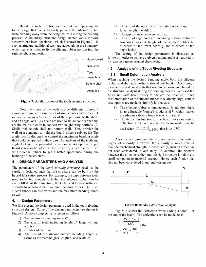
Based on such insights, we focused on improving the tooth design that can effectively prevent the silicone rubber from breaking away from the designed teeth during the bending process. A boundary structure design named tooth riveting structure has been developed, which is shown in Figure 7. In such a structure, additional teeth are added along the boundary, which serve as rivets to fix the silicone rubber portion into the rigid neighboring portion.
Figure 7: An illustration of the tooth riveting structure.
Note the shape of the teeth can be different. Figure 7 shows an example by using a set of simple cubes as the teeth. A tooth riveting structure consists of three portions: teeth, shells and an angle lock. (1) Teeth are used to fix silicone rubber and are the main structure to connect two neighboring portions. (2) Shells include side shell and bottom shell. They provide the wall of a container to hold the liquid silicone rubber. (3) The angle lock is designed to control the maximum bending angle that could be applied to the crease. An analysis of the teeth and angle lock will be presented in Section 4. An optional upper board can also be added in the structure, which can be filled with silicone rubber to get a better appearance during the bending of the structure.
4 DESIGN PARAMETERS AND ANALYSIS The parameters of the tooth riveting structure needs to be carefully designed such that the structure can be built by the hybrid fabrication process. For example, the gaps between teeth need to be big enough such that the silicone rubber can be easily filled. At the same time, the teeth need to have sufficient strength to withstand the maximum bending forces. The filled silicon rubber can also withstand the maximum bending forces as well.
4.1 Design Parameters We first present the design parameters used in the tooth riveting structure design. Some of the design parameters are shown in Figure 7. A more complete list is given as follows.
1) The maximum bending angle α ; 2) The size of teeth including height H, length m, and
width n; 3) Number of teeth: N; 4) The size of the silicone rubber including height H
(same as the teeth height), length L, and width b;
5) The size of the upper board including upper length c , lower length a, width b;
6) The gap distance between teeth: g; 7) The size of angel lock size including distance between
two angle locks d, height of the silicone rubber H, thickness of the lower board q, and thickness of the angle lock p.
The setting of the design parameters is discussed as follows in order to achieve a given bending angle as required in a crease in a given origami sheet design.
4.2 Analysis of the Tooth Riveting Structure
4.2.1 Small Deformation Analysis When reaching the desired bending angle, both the silicone rubber and the rigid portions should not break. Accordingly there are several constraints that need to be considered based on the structural analysis during the bending process. We used the Euler–Bernoulli beam theory to analyze the structure. Since the deformation of the silicone rubber is relatively large, certain assumptions are made to simplify its analysis.
1) The silicone rubber is homogenous. In addition, there is an adjustable Young’s modulus *E , which makes the silicone rubber a linearly elastic material.
2) The deflection function of the beam works in certain deflection limit. We assume the beam model can be
used when tan10%
α αα−
≤ , that is 030α ≤ .
Also, in our problem, the silicone rubber has certain degree of viscosity. However, the viscosity is much smaller than the mechanical strength. Consequently, such an effect has not been considered in our study. In addition, the friction between the silicone rubber and the rigid structure is relatively small compared to material strength. Hence such friction has also not been considered in our analysis model.
α
cw
Figure 8: Bending deflection analysis.
Figure 8 shows the deflection when adding a force P at the end of the beam. The deflections can be modeled as:
2
*
(3 )6x
Px L xwE I
−=
, and 3 2
* *3 3cPL MLwE I E I
= =,
Upper board
Side shell
Teeth
Lower board
Bottom shell
Angle lock
5
where cw is the deflection of the rubber beam, *E is the
adjustable Young’s modulus, and I is the second moment of the cubic area (i.e.
3
12bHI = ).
The relationship between bending angle α and the
moment M can be derived as: 2
* * * 3
6tan2 2
xx L
dw PL ML MLdx E I E I E bH
α == = = =
Thus, * 3tan
6E bHML
α ×=
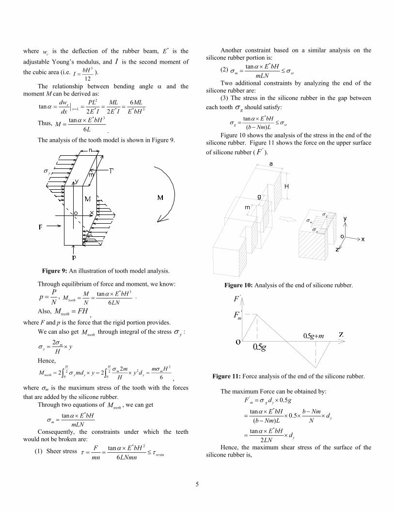
. The analysis of the tooth model is shown in Figure 9.
yσ
Figure 9: An illustration of tooth model analysis.
Through equilibrium of force and moment, we know: PpN
= , * 3tan
6teethM E bHMN LN
α ×= = .
Also, teethM FH= ,
where F and p is the force that the rigid portion provides. We can also get teethM through integral of the stress yσ :
2 my y
Hσσ = ×
Hence,
222 2
0 0
22 26
H Hm m
teeth y y ym m HM md y y d
Hσ σσ= × = × =∫ ∫ ,
where σm is the maximum stress of the tooth with the forces that are added by the silicone rubber.
Through two equations of teethM , we can get *tan
mE bH
mLNασ ×
=
Consequently, the constraints under which the teeth would not be broken are:
(1) Sheer stress * 2
sintan
6 reF E bH
mn LNmnατ τ×
= = ≤
Another constraint based on a similar analysis on the silicone rubber portion is:
(2) *tan
m srE bH
mLNασ σ×
= ≤
Two additional constraints by analyzing the end of the silicone rubber are:
(3) The stress in the silicone rubber in the gap between each tooth gσ should satisfy:
*tan( )g sr
E bHb Nm Lασ σ×
= ≤−
Figure 10 shows the analysis of the stress in the end of the silicone rubber. Figure 11 shows the force on the upper surface of silicone rubber ( 'F ).
gσmσ
gσ
Figure 10: Analysis of the end of silicone rubber.
'F
0.5g0.5g m+
'mF
Figure 11: Force analysis of the end of the silicone rubber.
The maximum Force can be obtained by: '
*
*
0.5
tan 0.5( )
tan2
m g y
y
y
F d g
E bH b Nm db Nm L N
E bH dLN
σ
α
α
= ×
× −= × × ×
−
×= ×
Hence, the maximum shear stress of the surface of the silicone rubber is,
6
' *' tan
( ) 2 ( )m
y
F E bHa n d LN a n
ατ ×= =
− −
The fourth constraint under which the silicone rubber would not break is:
(4)*
' tan2 ( ) sr sr
E bHLN a nατ τ σ×
= ≤ ≈−
From constraint (2) and (3), it can be seen that the length of a tooth and the gaps between them will affect the parameter setting and the effect of the constraints. An adjustable parameter k can be set as:
b kNm= , 1k > From constraint (2) and (3), we can also know constraint
(2) will apply when 2k ≥ ; while constraint(3) will apply when 2k < .
To make the design problem simpler, we set 2k = , which means the length of the tooth and the length of the gap between them is equivalent. Then the constraints can be simplified as:
(a) * 2
sintan
3 reF E H
mn Lnατ τ×
= = ≤
(b) *2 tan
m g srE H
Lασ σ σ×
= = ≤
(c) *
' tan2 ( ) sr sr
E bHLN a nατ τ σ×
= ≤ ≈−
4.2.2 Large Deformation Analysis When 030α ≥ , we assume that the deformation of the silicone rubber is close to an arc as shown in Figure 12. Hence the relation between the maximum extended length 'L and the bending angle α is:
'
2HL L α
= +
α
'L''LLL
Figure 12: Large deformation model analysis.
Hence the maximum strain and the corresponding stress on the surface of the silicone rubber are:
'
2ML L H
L Lαε −
= =
**
2M ME HE
Lασ ε= =
We can also get the maximum stress in the gap between the teeth as:
*max
2 ( )g srb E H b
b Nm L b Nmσ ασ σ= = ≤− −
By setting 2b Nm= , the constraint is
(1) *
g m srE H
Lασ σ σ= = ≤
Similar to the analysis as shown for the case of 030α ≤ , we can get two additional constraints as follows.
(2) The maximum sheer stress in teeth, 2
0
222
0
* 2
sin
2
226
6
H
y yteeth
Hmm
y
re
md yMFmn Hmn Hmn
m Hm y dHHmn Hmn
E HLn
στ
σσ
α τ
×= = =
×= =
= ≤
∫
∫
(3)The maximum sheer stress in the silicone rubber, ' *
' 0.5( ) ( ) 2 ( )
g ymsr
y y
d gF E H ma n d a n d L a n
σ ατ τ×
= = = ≤− − −
Consequently, the constraints for the case of 030α ≥ are:
(1) *
g m srE H
Lασ σ σ= = ≤
(2) * 2
sin6 reE H
Lnατ τ= ≤
(3) *
'
2 ( ) sr srE H mL a n
ατ τ σ= ≤ ≈−
4.3 Design and Analysis of Angle Lock To prevent a crease to be bent over an angular limitation for which it has been designed for, we integrate an angle lock design in the origami structure. The angle lock design is shown in Figure 13. The two angle lock parts are set beneath the bending structure such that they will touch each other when the two neighboring units are bent to a preset angle. Consequently the crease will not be able to be bent further. This enable us to control the folding angle along the creases and to prevent the silicon rubber will break accidently.
Figure 13: Design and analysis of the angle lock.
7
The relationship between the degree of angle and the design parameters of the angle lock can be obtained as below:
0.5d
H q pα =
+ + ,
where α is the degree of bending angle, d is the distance between two angle locks, H is the height of the silicone rubber, q is the thickness of the lower board, and p is the thickness of the angle lock.
Figure 14 shows the angle locks designed for three different maximum angles at 30o, 60o, and 90o, respectively. The tests of such angle locks by bent them to the related maximum angles are also shown in the figure.
Figure 14: Tests on the angle lock design.
4.4 Settings of Design Parameters For a given bending angle α , the design of tooth riveting structure can be performed based on the aforementioned design constraints, and the fabrication constraints in the used AM system and the silicon modeling processes. The setting of parameters ( , , , , , , , , , , ,H m n N L b a c g d q p ) can be obtained through the following steps for a given crease with the maximum bending angle α:
(1) According to the crease size, set the parameter b and H. When setting H, we need to consider the thickness of the upper board and the lower board. Typically, we set the thickness between 0.2~0.5mm based on the AM system that is used in our experiments;
(2) Use corresponding constraints to set proper L based on the range of angle α;
(3) Set proper n based on the equations as well as the fabrication constraint n ≥ 0.8mm;
(4) Set proper m and N based on b= 2Nm as well as the fabrication constraint m ≥ 0.8mm; In addition, g can be set through m = g;
(5) Set proper a based on constraints of maximum sheer stress;
(6) Set d, q, and p based on the angle lock equations. Typically, we can set q between 0.2~0.5mm and p between 1~2mm to get a good performance;
(7) Set parameter c. In our experiments we typically set c between 2~6mm.
The process of parameter setting is shown in Figure 15.
α
H
L
n
N g
a
q
m
b
c
p d
Figure 15: Flow chart of the setting of all the parameters.
Figure 16: Automatic design of a CAD model for a given origami sheet design.
5 AUTOMATIC DESIGN OF FOLDABLE ORIGAMI SHEET
There can be hundreds of creases in a typical origami sheet design. Each crease may have different folding angle requirements. To automate the construction of a CAD model for such an origami sheet, we developed an origami sheet designer as shown in Figure 16. A desired 3D structure can be unfolded into a 2D origami sheet design. For each crease with given maximum bending angle αi, the design parameters related to the tooth riveting structure for such a crease can be computed based on the procedure discussed in Section 4. A CAD template of the tooth riveting structure can be loaded into a CAD software system. In our research we used SolidWorks from Dassault Systems (Waltham, MA), which provides a set of Application Programming Interface (API) for direct access to SolidWorks functionality. Based on the computed design parameters including ( , , , , , , , , , , ,H m n N L b a c g d q p ), an
8
appropriate CAD model of the tooth riveting structure can be constructed for the given crease. Finally a CAD model of the origami sheet can be computed by performing Boolean operations between all the crease models and a CAD model related to non-crease portions. Such a CAD model can then be sent to an additive manufacturing system to be fabricated.
6 EXPERIMENTAL TESTS
6.1 Materials Properties The mechanical properties of the materials used in our origami sheet tests are listed as follows. The flexural strength of the SI500 resin is 65MPa, that is,
sin 65re MPaτ = . The tensile strength of the VytaFlex®20 Urethane Rubber is 200psi or 1.38MPa, that is, 1.38sr sr MPaτ σ≈ = . We do not have an accurate number of the adjustable Young’s modulus *E of the silicone rubber. The website of MATBASE, a website on material property data, gives a commonly used range for silicon rubber as 1~5Mpa. Accordingly we set *E as 3Mpa, the mean value of the range.
6.2 Tooth Riveting Design Validation The experimental steps are listed as follows:
(1) Set the design parameters of the tooth riveting structures for all the creases.
(2) Construct a 3D CAD model of the origami sheet based on the parameter settings;
(3) Use AM software system to add support structures for the constructed CAD model;
(4) Use AM software system to slice the CAD model with support structures to generate a set of slicing images for the Ultra machine;
(5) Fabricate the parts using the Ultra machine; (6) Clean and dry the fabricated parts; (7) Mix the VytaFlex®20 Urethane Rubber for about
5min. Then pour the liquid to fill the designed structure to define the creases.
(8) After waiting for about 16 hours, remove the support structures as well as the thin shells that are used as the containers in the design.
(9) Fix the fabricated objects and measure the degree of bending angle. In our experiments, we used a cylinder pen cap and transparent tape to fix the resin portions. As shown in Figure 14, we also used an angular diagram to measure the bending angle.
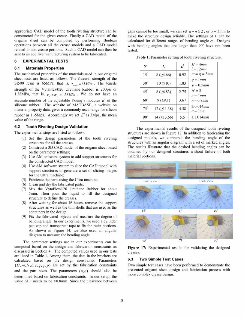
The parameter settings use in our experiments can be computed based on the design and fabrication constraints as discussed in Section 4. The computed values used in our tests are listed in Table 1. Among them, the data in the brackets are calculated based on the design constraints. Parameters ( , , , , , , , )H m N b c g q p are set by the fabrication constraints and the part sizes. The parameters ( , )n a should also be determined based on fabrication constraints. In our setup, the value of n needs to be >0.8mm. Since the clearance between
gaps cannot be too small, we can set 2a n− ≥ , or a = 3mm to make the structure design reliable. The settings of L can be calculated for different ranges of bending angle α . Designs with bending angles that are larger than 90o have not been tested.
Table 1: Parameter setting of tooth riveting structure.
α L d 4H mm=12b mm=
3m g mm= = 1q mm= 0.5p mm= 3N =
4c mm= 0.8
0.014n mm
mm=
≥3
1.014a mm
mm=
≥
150 8 (≥4.66) 0.92
300 10 (≥10) 1.83
450 8 (≥6.83) 2.75
600 9 (≥9.1) 3.67
750 12 (≥11.38) 4.58
900 14 (≥13.66) 5.5
The experimental results of the designed tooth riveting
structures are shown in Figure 17. In addition to fabricating the designed models, we compared the bending angle of the structures with an angular diagram with a set of marked angles. The results illustrate that the desired bending angles can be obtained by our designed structures without failure of both material portions.
Figure 17: Experimental results for validating the designed creases.
6.3 Two Simple Test Cases Two simple test cases have been performed to demonstrate the presented origami sheet design and fabrication process with more complex crease design.
9
6.3.1 A Folded Box Model Figure 18 illustrates the design and fabrication processes in making a simple box model based on our approach. In the figure, an origami sheet using a piece of paper is also shown for a comparison. In the test the fabricated structure was folded by hand. The addition of an actuation mechanism to make the sheet to be self-foldable is interesting and will be investigated in our further work.
Figure 18: Fabrication of a folded box based on the developed origami sheet fabrication method.
6.3.2 A Triangular Pyramid Model Figure 19 illustrates the design and fabrication processes in making a triangular pyramid model based on our approach. Similarly, an origami sheet based on a piece of paper is shown in the figure. The structure was also folded by hand in the test.
6.4 A Small Size Model The structures fabricated by the AM process can be in any scale levels. In addition to macro-scale size, the origami sheet idea can be used in meso- or micro-scales as well. To illustrate the idea, Figure 20 shows two parts that were fabricated using the same CAD model but with two different scales of sizes. One is in the macro-scale and another is in the meso-scale. In the future, a micro-scale AM process can also be used in fabricating the designed tooth riveting structures. Hence the presented process can be used in design and fabricating foldable origami sheets with desired creases for reconfigurable product components in various size scales.
Figure 19: Fabrication of a triangular pyramid based on the developed origami sheet fabrication method.
Figure 20: Tooth riveting structures in smaller scales.
7 CONCLUSIONS AND FUTURE WORK Design of reconfigurable structures based on folding mechanisms is an interesting and important topic for future engineering systems. In the paper we presented an origami sheet idea for designing and fabricating foldable structures. Two different materials are used in an origami sheet based on additive manufacturing and silicon molding technologies. In the origami sheet, the creases can be in any shape and have varying requirements on the maximum bending angles. A tooth riveting structure was presented to modify the boundary of creases such that the related creases can be bent to a desired angle without failure. The Euler-Bernoulli beam theory was used in modeling the crease bending. The design parameters of the tooth riveting structure can be computed based on both design and fabrication constraints. Accordingly the CAD model of an origami sheet
10
with desired tooth riveting structures for the given crease can be automatically constructed. The constructed CAD model can then be built by the hybrid manufacturing process. Experiments have been conducted to test the presented design and fabrication process. The test results verified that the fabricated origami sheets can achieve desired folding requirements. In addition, the origami sheets with related tooth riveting structures can be in different size scales.
Our future work includes: (1) better analysis of the designs with large deformations such that designs with bending angle larger than 900; (2) theoretical analysis and development of better foldable structures; and (3) test the ideas of micro-scale structures and more complex 3D structures.
REFERENCES 1. Kato J, Shimanuki H, Watanabe T. Automatically making
origami diagrams. In: Berlin, Heidelberg: Springer Berlin Heidelberg; 2008. p. 1-8.
2. Kato, J., Shimanuki, H., Watanabe, T.: Understanding and Reconstruction of Folding Process Explained by a Sequence of Origami illustrations. In: the Fourth International Conference on Origami in Science, Mathematics, and education, Pasadena, California, USA, Septmeber 8-10 (2006)
3. Cheng HY, Cheong KH. Designing crease patterns for polyhedra by composing right frusta. Computer-Aided Design. 2012;44(4):331-42
4. Lang, Robert J. (Robert James), ebrary I. Origami design secrets: Mathematical methods for an ancient art. Natick, MA: A K Peters, Limited, 2003.
5. Yao W, Dai JS. Dexterous manipulation of origami cartons with robotic fingers based on the interactive configuration space. Journal of Mechanical Design. 2008;130(2):22303.
6. Kenta Tanaka, Yusuke Kamotani and Yasuyoshi Yokokohji. Origami Folding by a Robotic Hand. Proceedings of the 2007 IEEE/RSJ International Conference on Intelligent Robots and Systems, San Diego, CA, USA, Oct. 29th – Nov. 2nd, 2007.
7. Yoonjin Kim. Hierarchical multiplexing interconnection structure for fault-tolerant reconfigurable chip multiprocessor. Journal of Semiconductor Technology and Science. Vol. 11(4), pp. 318-28, 2011.
8. Todoroki A, Matsuzaki R, Kumagai K. Self-deployable space structure using partially flexible CFRP with SMA wires. Journal of Intelligent Material Systems and Structures. Vol. 20(12), pp. 1415-24, 2009.
9. Steve Upcraft, Richard Fletcher. The rapid prototyping technologies, Assembly Automation, Vol. 23, 4, pp. 318-310, 2003.
10. Pham, D. T., S. S. Dimov. Rapid prototyping and rapid tooling—the key enablers for rapid manufacturing, Mechanical Engineering Science, Proc. Instn Mech. Engrs, Vol. 217, Part C: C02402, 2003.
11. Dana E. Vogtmann, Satyandra K. Gupta, and Sarah Bergbreiter, Multi-Material Compliant Mechanisms for Mobile Millirobots, 2011 IEEE International Conference on Robotics and Automation Shanghai International Conference Center, May 9-13, Shanghai, China, 2011.
12. Smooth-On: www.smooth-on.com, accessed in May 2012. 13. Amadori K, Tarkian M, Olvander J, Krus P. Flexible and