139
| Date post: | 18-Oct-2018 |
| Category: |
Documents |
| Upload: | trinhkhanh |
| View: | 224 times |
| Download: | 0 times |
Detection and Decoding Algorithms ofMulti-Antenna Diversity Techniques for
Terrestrial DVB Systems
Iker Sobrón Polancos
Supervisors:
Mikel Mendicute Errasti
and
Jon Altuna Iraola
MONDRAGON
UNIBERTSITATEA
A thesis submitted for the degree of
Doctor por Mondragon Unibertsitatea
Department of Electronics and Computer Science
Mondragon Goi Eskola Politeknikoa
Mondragon Unibertsitatea
November 2010


Para aita, ama, Josu e Itziar
Y para Irene
When you make the �nding yourself
- even if you're the last person on Earth to see the light -
you'll never forget it.
Carl Sagan

Agradecimientos
A lo largo de estos cuatro años de singladura, he tenido la suerte de cruzarme con muchas
personas que me han ayudado a que este barco arribe a puerto. Su apoyo, guía y consejo ha
permitido que en todo momento tuviera un norte al que dirigirme sin que perdiera el ánimo
para continuar hacia adelante. Es por ello que quiero expresar en las siguientes líneas mi
más profundo agradecimiento a cada una de ellas, haciéndolas también protagonistas de este
momento.
En primer lugar, agradezco a mis directoresMikel Mendicute y Jon Altuna su apoyo
y consejo en los momentos de zozobra, además de la con�anza depositada en mí para la
realización de esta tesis. Me gustaría dedicar particularmente un especial gracias a Mikel,
por su in�nita paciencia y todo ese valioso tiempo que me ha dedicado desde los comienzos
como compañero de despacho hasta hoy, además de por el buen amigo que he tenido la suerte
de conocer. También quisiera agradecer a Vicente Atxa, Jose Mari Zabalegui y Javier
Del Ser los consejos, recomendaciones y ayuda en los dos primeros años de tesis.
Agradezco a Mondragon Goi Eskola Politeknikoa la oportunidad ofrecida gracias
a su �nanciación y medios para el desarrollo de esta investigación. También agradezco a
mis compañeros de departamento, Ane Antía, Nestor Arana, Eñaut Muxika, Alberto
Izaguirre y Aitzol Iturrospe, el cordial y acogedor trato que me han dado durante todo
este tiempo. Doy las gracias especialmente, a Javier Oyarzun por allanarme el camino en
los difíciles momentos de la escritura de tesis, a Unai Garro por sus e�cientes gestiones
con Tux y a Egoitz Arruti, por la con�anza depositada y las facilidades ofrecidas para la
consecución de mi trabajo.
Quiero dar las gracias a los miembros del grupo de televisión digital del Departa-
mento de Tecnología de la Información en la Universidad de Turku, especialmente
a Jarkko Paavola, Jari Tissari y Jussi Poikonen, por darme la oportunidad de realizar
una estancia con ellos y ayudarme a desarrollar mi trabajo de investigación.
Por otro lado, debo expresar mi más cálida gratitud a los compañeros de batalla que año
tras año han ido entrando en mi vida doctoranda. Ellos han hecho el día a día más ameno y
han soportado estoicamente mis delirios y preocupaciones a lo largo de todos estos años. Por
iii
orden ascendente de antigüedad, agradezco a Joxe Aixpurua, Maite Beamurgia, Lorea
Belategui, Iñaki Garitano y Aritz Legarda, los buenos momentos de café que me han
ayudado a desconectar en estos últimos meses de escritura; a Idoia Jiménez, su agradable
compañía, especialmente en esas mañanas cuando Garaia despierta; a Pello Ochandiano
y Lorena Martínez, el compartir tantos quebraderos de cabeza en el diseño del simulador
y los interesantes momentos de discusión que hemos vivido. Y por último, a Maitane
Barrenechea, su inestimable ayuda en la comprensión y el diseño del decodi�cador esférico,
y su agradable compañía todo este tiempo.
Finalmente, me gustaría agradecer a las personas más cercanas a mí, su con�anza, pa-
ciencia, ánimos y comprensión. A mis amigos que han soportado con estoico aguante mis
cifrados soliloquios de procesado de señal. Con especial cariño, a mi familia que me ha
dado muchos ánimos para alcanzar esta meta, aita, ama, mi hermano Josu y mi hermana
Itziar, que si no hubiera sido por ellos, nunca podría haber sido lo que soy. Y para acabar, a
Irene, que ha estado ahí en todo momento para apoyarme, ayudarme o escucharme siempre
y cuando lo necesitaba.
Acknowledgments
Throughout this four-year journey, I had the chance of meeting several people who have
helped me to the completion of this PhD thesis. Their encouragement, guidance and advise
have allowed me to �nd the correct way and go ahead all the time. For that reason, I would
like to express my deepest gratitude to each of them and make them active participants in
this moment.
First of all, I am grateful for the assistance and guidance of my supervisors, Jon Altuna
and Mikel Mendicute, as well as for the con�dence and faith they showed on me. I
particularly wish to thank Mikel who helped me with great patience from the beginning
of my research until today, as well as being a good friend. Furthermore, I thank Vicente
Atxa, Jose Mari Zabalegui and Javier Del Ser for their comments and advises at the
two �rst years of the research.
I would like to thank University of Mondragón for funding and providing me all the
necessary equipment to carry out this PhD thesis. Also I am grateful to my department
colleagues, Ane Antía, Nestor Arana, Eñaut Muxika, Alberto Izaguirre and Aitzol
Iturrospe, for their warm and kind relationship with me along this time. Special thanks to
Javier Oyarzun who gave me the time I needed to write this work, to Unai Garro for his
skills in the Tux's world and to Egoitz Arruti for his con�dence and the facilities provided
for the develop of my work.
I also want to thank the DTV Group from the Department of Information Tech-
nology at the University of Turku, specially Jarkko Paavola, Jari Tissari and Jussi
Poikonen, for giving me the chance of visiting them and discussing di�erent matters with
them.
On the other hand, I am so grateful to my PhD comrades-in-arms who accompanied
me along the last three years. In ascending order of seniority, I wish to express my sincere
gratitude to Joxe Aixpurua,Maite Beamurgia, Lorea Belategui, Iñaki Garitano and
Aritz Legarda, for the nice co�ee breaks in the last months of writing; to Idoia Jiménez
for her kind company and encouragement, specially in the quiet and early mornings of
Garaia; to Pello Ochandiano and Lorena Martínez, for sharing so many headaches
v

building the DVB-T2 framework over which we have performed our researches and for the
helpful discussions we had; and �nally, toMaitane Barrenechea for her help to the sphere
decoder understanding and develop, as well as her kind company all this time.
And last, I would like to express my deepest gratitude to the closest-to-me people for
their con�dence, pacience, encouragement and comprehension. Tomy friends who stoically
listened to my coded soliloquies about signal processing. To my dear family who encouraged
me to go ahead, my parents, my brother Josu and my sister Itziar. They gave me all the
facilities to be what I am. And �nally, to Irene, who has patiently supported and helped
me along this time.
Abstract
This PhD dissertation analyzes the behavior of multi-antenna diversity techniques in broad-
casting scenarios of TDT (terrestrial digital television) systems and proposes a low-complexity
detection and decoding design for their practical implementation. For that purpose, the
transmission-reception chains of the European DVB-T (Digital Video Broadcasting - Ter-
restrial) and DVB-T2 standards have been implemented over which diversity and MIMO
(multiple-input multiple-output) techniques have been assessed through Monte Carlo simu-
lations.
On one hand, the most important multi-antenna diversity techniques such as CDD (cyclic
delay diversity), Alamouti code-based SFBC (space-frequency block coding) and MRC (max-
imum ratio combining), have been evaluated in a DVB-T system over both �xed and mobile
Rayleigh and Ricean channels. With the DVB-T2 standard release, multi-antenna processing
has actually been introduced in digital television systems. The distributed SFBC con�gura-
tion proposed in DVB-T2 is analyzed from a performance point of view considering di�erent
propagation conditions in an SFN (single frequency network).
On the other hand, error-performance and detection complexity analyses of 2× 2 FRFD
(full-rate full-diversity) SFBCs are carried out for last-generation DTV (digital television)
systems. The use of channel coding based on LDPC (low-density parity check) codes in new
standards such as DVB-T2, involves a soft-output MAP (maximum a posteriori) detection
which results in an increase of the detection complexity. In order to study the FRFD codes
behavior in such a BICM (bit-interleaved coded modulation) scheme, the Golden code, which
achieves the maximum coding gain, and the Sezginer-Sari code, which has a lower inherent
detection complexity as an expense of sacri�cing performance gain, have been chosen. Using
LSD (list sphere decoder) detection, BER (bit error rate) performance and computational
cost results are provided for TDT scenarios.
In order to overcome the variable complexity of the LSD, LFSD (list �xed-complexity
sphere decoder) detection is proposed for practical implementations. A redesign of the previ-
ously proposed LFSD algorithm for spatial multiplexing MIMO systems has been performed
for FRFD SFBCs with close-to-LSD performance. Furthermore, an analysis of the number
vii

of candidates is carried out in order to maximize the e�ciency of the algorithm. Due to
its �xed complexity, the novel algorithm can be fully pipelined making feasible a realistic
implementation in chip.
Resumen
Esta tesis analiza el comportamiento de las técnicas de diversidad multiantena en escenarios
de radiodifusión TDT (televisión digital terrestre) y propone un diseño de baja complejidad
para la detección de códigos SFBC (space-frequency block coding) que facilita una posible
implementación práctica. Para ello, se ha implementado la cadena de transmisión-recepción
de los estándares europeos DVB-T (Digital Video Broadcasting - Terrestrial) y DVB-T2
como entorno de trabajo donde se han incluido y simulado diferentes técnicas de diversidad
MIMO (multiple-input multiple-output).
Por un lado, se evalúan las técnicas de diversidad multiantena CDD (cyclic delay diver-
sity), SFBC con codi�cación Alamouti y MRC (maximum ratio combining) en escenarios
�jos y móviles de canales tanto Rayleigh como Ricean para el sistema DVB-T. En DVB-T2,
se analiza la tecnología multiantena propuesta por el estándar para diferentes escenarios de
propagación dentro de redes SFN (single frequency network).
Por otro lado, se realiza un estudio sobre códigos FRFD (full-rate full-diversity) SFBC
para su posible inclusión en futuros estándares de televisión digital. El uso de codi�ca-
ciones de canal más potentes, como los códigos LDPC (low-density parity check), implica la
utilización de una detección MAP (maximum a posteriori) con salida soft, incrementando
considerablemente la complejidad de la detección. Para realizar el correspondiente análisis
de complejidad y rendimiento, se han escogidos dos códigos FRFD. Por un lado, el código
Golden, que ofrece la máxima ganancia de código y, por otro, el código propuesto por Sezginer
y Sari, que consigue reducir la complejidad de detección a costa de perder cierta ganancia de
código. Se presentan resultados basados en curvas de BER (bit error rate) y número de ope-
raciones sobre un sistema BICM (bit-interleaved coded modulation) equivalente a DVB-T2
en escenarios TDT utilizando una detección LSD (list sphere decoder).
Para resolver el problema de la complejidad variable del algoritmo LSD, se realiza un
rediseño del ya propuesto LFSD (list �xed-complexity sphere decoder) para técnicas de mul-
tiplexación espacial considerando la estructura de los códigos FRFD SFBC. Asimismo, se
evalúa el número de candidatos que ofrece un funcionamiento más e�ciente con menor coste
computacional. Los resultados de simulación basados en curvas de BER muestran rendimien-
ix

tos cercanos al detector LSD manteniendo el número de operaciones constante. Por lo tanto,
este nuevo diseño permite su e�ciente y práctica implementación en dispositivos reales.

Laburpena
Doktoretza-tesi honen gai nagusia Lurreko Telebista Digitalerako antena anitzeko dibertsi-
tate tekniken portaera ikertzea da, hartzailerako konplexutasun baxuko algoritmoen diseinua
oinarri hartuta. Horretarako, Europako DVB-T eta DVB-T2 telebista digitaleko estandarren
igorle-hartzaile kateen simulagailua inplementatzeaz gain, dibertsitate eta MIMO (multiple-
input multiple-output) algoritmoak garatu eta aztertu dira.
Lehenengo helburu gisa, CDD (cyclic delay diversity), Alamouti kodean oinarritutako
SFBC (space-frequency block coding) eta MRC (maximum ratio combining) teknikak ebalu-
atu dira Rayleigh eta Ricean ingurunetan, bai komunikazio �nko zein mugikorretarako.
Argitaratu berri den DVB-T2 estandarrak antena anitzeko prozesaketa telebista sistema
digitalean sartu duenez, teknologia honen analisia egin da maiztasun bakarreko telebista
sareetarako SFN (single frequency network).
Tesiaren helburu nagusia FRFD (full-rate full-diversity) SFBC kodigoen ikerketa eta
hauek telebista digitalaren estandar berrietan sartzea ahalbidetuko dituzten detekzio siste-
men diseinua izan da. Kanalen kodi�kazio indartsuagoak erabiltzeak, LDPC (low-density
parity check) kodeak esaterako, MAP (maximum a posteriori) algoritmoan oinarritutako
soft irteeradun detektoreen erabilera dakar berekin, detekzioaren konplexutasuna areagotuz.
Bi FRFD kode aukeratu dira errendimendu eta konplexutasun analisiak DVB-T2 bezalako
BICM (bit-interleaved coded modulation) sistemetan egiteko. Alde batetik, irabazi maximoa
lortzen duen Golden kodea eta, bestetik, konplexutasun txikiagoa duen Sezginer eta Sarik
proposatutako kodea erabili dira. Bit errore edo BER (bit error rate) tasan eta konputazio
kostuan oinarrituta, emaitzak aurkeztu dira zerrenda dekodeatzaile esferikoa (list sphere
decoder, LSD) erabiliz.
LSD-aren konplexutasun aldakorraren arazoa konpontzeko, ezpazio-multiplexazioko tek-
nikarako LFSD (list �xed-complexity sphere decoder) algoritmoaren berdiseinua garatu da,
FRFD SFBC kodeen egitura berezia kontuan hartuta. Algoritmoaren eraginkortasuna ma-
ximizatzeko kandidatuen zenbakia ebaluatzen da baita ere. LSD-en antzeko errendimendua
duten BER gra�ketan oinarritutako simulazio emaitzak aurkezten dira, eragiketa kopurua
konstante eta LSD-arenaren baino murritzagoa mantenduz. Beraz, proposatutako diseinu
xi

eraginkorrak, FRFD SFBC antena anitzeko dibertsitatean oinarritutako eskemen inplemen-
tazioa ahalbidetu dezakete telebista digitalaren estandar berrietarako.

Declaration of Originality
I hereby declare that the research recorded in this thesis and the thesis itself were devel-
oped entirely by myself at the Signal Theory and Communications Area, Department of
Electronics and Computer Science, at the University of Mondragon.
The software used to perform the simulations was developed entirely by myself, with the
following exceptions:
• The implementation of the basic transmission-reception chain of the DVB-T2 simulator
has been jointly designed by Lorena Martínez, Pello Ochandiano and me.
• The implementation of the list �xed sphere decoder has been jointly designed by Mai-
tane Barrenechea and me.
Iker Sobrón Polancos
Department of Electronics and Computer Science
Mondragon Goi Eskola Politeknikoa
Mondragon Unibertsitatea
November, 2010
xiii

Contents
Acknowledgments . . . . . . . . . . . . . . . . . . . . . . . . . . . . . . . . . . . . iii
Abstract . . . . . . . . . . . . . . . . . . . . . . . . . . . . . . . . . . . . . . . . . vii
Declaration of Originality . . . . . . . . . . . . . . . . . . . . . . . . . . . . . . . xiii
Contents . . . . . . . . . . . . . . . . . . . . . . . . . . . . . . . . . . . . . . . . . xiv
List of Figures . . . . . . . . . . . . . . . . . . . . . . . . . . . . . . . . . . . . . . xvi
List of Tables . . . . . . . . . . . . . . . . . . . . . . . . . . . . . . . . . . . . . . xix
List of Symbols . . . . . . . . . . . . . . . . . . . . . . . . . . . . . . . . . . . . . xxvi
1 Introducción 1
1.1 Motivación y Objetivos . . . . . . . . . . . . . . . . . . . . . . . . . . . . . . 2
1.2 Contribuciones de la Tesis . . . . . . . . . . . . . . . . . . . . . . . . . . . . 3
1.3 Estructura de la Tesis . . . . . . . . . . . . . . . . . . . . . . . . . . . . . . 4
2 Background and Related Work 6
2.1 Introduction . . . . . . . . . . . . . . . . . . . . . . . . . . . . . . . . . . . . 6
2.2 Terrestrial Digital Television . . . . . . . . . . . . . . . . . . . . . . . . . . . 6
2.2.1 DVB-T . . . . . . . . . . . . . . . . . . . . . . . . . . . . . . . . . . . 7
2.2.1.1 MPEG-2 Source Coding and Multiplexing . . . . . . . . . . 7
2.2.1.2 Channel Coding . . . . . . . . . . . . . . . . . . . . . . . . 8
2.2.1.3 Modulation . . . . . . . . . . . . . . . . . . . . . . . . . . . 8
2.2.2 DVB-T2 . . . . . . . . . . . . . . . . . . . . . . . . . . . . . . . . . . 9
2.2.2.1 Bit Interleaved Coded Modulation . . . . . . . . . . . . . . 9
2.2.2.2 Frame Builder . . . . . . . . . . . . . . . . . . . . . . . . . 10
2.2.2.3 OFDM Generation . . . . . . . . . . . . . . . . . . . . . . . 10
2.3 Multi-Antenna Wireless Systems . . . . . . . . . . . . . . . . . . . . . . . . . 11
2.3.1 System and Channel Model . . . . . . . . . . . . . . . . . . . . . . . 12
2.3.2 Channel Capacity . . . . . . . . . . . . . . . . . . . . . . . . . . . . . 14
2.3.3 Diversity-Multiplexing Trade-O� . . . . . . . . . . . . . . . . . . . . 15
2.3.4 Diversity Types . . . . . . . . . . . . . . . . . . . . . . . . . . . . . . 16
xiv

2.3.4.1 Spatial Diversity . . . . . . . . . . . . . . . . . . . . . . . . 17
2.3.4.2 Time Diversity . . . . . . . . . . . . . . . . . . . . . . . . . 17
2.3.4.3 Frequency Diversity . . . . . . . . . . . . . . . . . . . . . . 18
2.3.4.4 Polarization Diversity . . . . . . . . . . . . . . . . . . . . . 18
2.3.4.5 Angular Diversity . . . . . . . . . . . . . . . . . . . . . . . . 18
2.3.5 Space-Time and Space-Frequency Diversity Techniques . . . . . . . . 18
2.3.5.1 Orthogonal Space-Time Block Coding . . . . . . . . . . . . 19
2.3.5.1.1 One Receive Antenna . . . . . . . . . . . . . . . . 19
2.3.5.1.2 Two Receive Antennas . . . . . . . . . . . . . . . . 20
2.3.5.1.3 Linear Detection Techniques . . . . . . . . . . . . . 21
2.3.5.2 Space-Frequency Block Coding . . . . . . . . . . . . . . . . 22
2.3.5.3 Cyclic Delay Diversity . . . . . . . . . . . . . . . . . . . . . 23
2.3.6 Full-Rate Full-Diversity Techniques . . . . . . . . . . . . . . . . . . . 24
2.3.6.1 The Golden Code . . . . . . . . . . . . . . . . . . . . . . . . 25
2.3.6.2 Low Complexity Codes . . . . . . . . . . . . . . . . . . . . . 26
2.3.6.2.1 The Silver Code . . . . . . . . . . . . . . . . . . . 26
2.3.6.2.2 The Sezginer-Sari Code . . . . . . . . . . . . . . . 27
2.3.6.3 Detection Techniques . . . . . . . . . . . . . . . . . . . . . . 27
2.3.6.3.1 Optimal Maximum Likelihood Detection . . . . . . 27
2.3.6.3.2 Sphere Decoding . . . . . . . . . . . . . . . . . . . 28
2.4 Chapter Summary . . . . . . . . . . . . . . . . . . . . . . . . . . . . . . . . 30
3 Multi-Antenna Diversity Schemes in DVB-T and DVB-T2 Broadcasting 31
3.1 Introduction . . . . . . . . . . . . . . . . . . . . . . . . . . . . . . . . . . . . 31
3.2 Fading Channels . . . . . . . . . . . . . . . . . . . . . . . . . . . . . . . . . 32
3.2.1 Rayleigh and Ricean Channels . . . . . . . . . . . . . . . . . . . . . . 32
3.2.2 Multipath Channel Models . . . . . . . . . . . . . . . . . . . . . . . . 34
3.2.2.1 TU6 and RA6 Channels . . . . . . . . . . . . . . . . . . . . 36
3.2.3 Single-Frequency Networks . . . . . . . . . . . . . . . . . . . . . . . . 37
3.3 Diversity Techniques in DVB-T . . . . . . . . . . . . . . . . . . . . . . . . . 40
3.3.1 Static Environments . . . . . . . . . . . . . . . . . . . . . . . . . . . 41
3.3.1.1 Previous Considerations About the CDD Technique . . . . . 41
3.3.1.2 Simulation Results . . . . . . . . . . . . . . . . . . . . . . . 43
3.3.2 Mobile Environments . . . . . . . . . . . . . . . . . . . . . . . . . . . 45
3.4 Diversity and Coding in DVB-T2 . . . . . . . . . . . . . . . . . . . . . . . . 46
3.4.1 Soft Detection: The Maximum a Posteriori Detection . . . . . . . . . 48
3.4.2 Rotated Constellations . . . . . . . . . . . . . . . . . . . . . . . . . . 49
3.4.3 The DVB-T2 SFBC . . . . . . . . . . . . . . . . . . . . . . . . . . . 52

3.5 Reception in SFN Networks . . . . . . . . . . . . . . . . . . . . . . . . . . . 53
3.5.1 Echoes in the SFN Network or Self-Interference . . . . . . . . . . . . 55
3.5.2 Distributed MISO Transmission in SFN Networks . . . . . . . . . . . 57
3.6 Chapter Summary . . . . . . . . . . . . . . . . . . . . . . . . . . . . . . . . 59
4 Soft-Output MIMO Detection in DVB-T2 61
4.1 Introduction . . . . . . . . . . . . . . . . . . . . . . . . . . . . . . . . . . . . 61
4.2 Soft Detection of SFBCs . . . . . . . . . . . . . . . . . . . . . . . . . . . . . 62
4.2.1 SFBC MAP Detection . . . . . . . . . . . . . . . . . . . . . . . . . . 62
4.2.2 Likelihood Function for SFBC MAP Detection . . . . . . . . . . . . . 62
4.2.3 List Detection . . . . . . . . . . . . . . . . . . . . . . . . . . . . . . . 64
4.2.4 Choice of Candidates Number . . . . . . . . . . . . . . . . . . . . . . 66
4.3 Performance Results of FRFD Schemes in DVB-T2 Broadcasting Scenarios . 66
4.4 Complexity of List Sphere Decoder-Based Soft Detectors . . . . . . . . . . . 70
4.4.1 List Sphere Decoder . . . . . . . . . . . . . . . . . . . . . . . . . . . 70
4.4.1.1 Complexity Results . . . . . . . . . . . . . . . . . . . . . . . 71
4.4.2 Review of Fixed-Complexity Implementations . . . . . . . . . . . . . 73
4.5 Chapter Summary . . . . . . . . . . . . . . . . . . . . . . . . . . . . . . . . 73
5 List Fixed-Complexity Sphere Decoder for FRFD Codes 77
5.1 Introduction . . . . . . . . . . . . . . . . . . . . . . . . . . . . . . . . . . . . 77
5.2 The LFSD Algorithm . . . . . . . . . . . . . . . . . . . . . . . . . . . . . . . 78
5.2.1 The Ordering Algorithm for FRFD SFBC . . . . . . . . . . . . . . . 80
5.2.1.1 SS Code . . . . . . . . . . . . . . . . . . . . . . . . . . . . . 80
5.2.1.2 Golden Code . . . . . . . . . . . . . . . . . . . . . . . . . . 81
5.2.2 Bit LLR Generation for the Proposed List Fixed-Complexity Detector 82
5.3 Simulation Results . . . . . . . . . . . . . . . . . . . . . . . . . . . . . . . . 83
5.3.1 E�ect of the Number of Candidates on the System Performance . . . 83
5.3.2 Comparative Analysis Between List Sphere Decoder and List Fixed-
Complexity Sphere Decoder . . . . . . . . . . . . . . . . . . . . . . . 85
5.3.3 Complexity Considerations . . . . . . . . . . . . . . . . . . . . . . . . 87
5.4 Chapter Summary . . . . . . . . . . . . . . . . . . . . . . . . . . . . . . . . 90
6 Summary and Conclusions 92
6.1 Thesis Contributions . . . . . . . . . . . . . . . . . . . . . . . . . . . . . . . 93
6.2 Suggestions for Further Research . . . . . . . . . . . . . . . . . . . . . . . . 94
A Publications 95
References 98

List of Figures
2.1 The DVB-T transmission scheme. . . . . . . . . . . . . . . . . . . . . . . . . 8
2.2 The DVB-T2 transmission scheme. . . . . . . . . . . . . . . . . . . . . . . . 10
2.3 Constellation rotation and cyclic Q-delay. . . . . . . . . . . . . . . . . . . . . 11
2.4 MIMO channel with M transmit and N receive antennas. . . . . . . . . . . . 12
2.5 Optimal diversity-multiplexing trade-o� curve for a two transmit and two
receive antenna transmission. . . . . . . . . . . . . . . . . . . . . . . . . . . 16
2.6 Comparison of optimal diversity-multiplexing trade-o� curve and diversity-
multiplexing trade-o� achieved by OSTBC for two transmit and two receive
antennas. . . . . . . . . . . . . . . . . . . . . . . . . . . . . . . . . . . . . . 21
2.7 SFBC transmission scheme of DVB-T2 system. . . . . . . . . . . . . . . . . 23
2.8 Schemes of delay diversity and cyclic delay diversity. . . . . . . . . . . . . . 24
2.9 Schematic of the sphere decoder search principle for the 2-dimensional case. . 28
3.1 Doppler power spectrum densities of channels TU6 and RA6 LOS. . . . . . . 38
3.2 Distributed MISO scheme in SFN. . . . . . . . . . . . . . . . . . . . . . . . . 39
3.3 Comparison of 2 × 1 CDD schemes in the DVB-T system over the channels
de�ned in [JTC93] varying the cyclic delay δ1 of the second antenna. . . . . 42
3.4 TU12 and RA6 channel snapshots for single antenna and CDD systems with
fd = 30 Hz. . . . . . . . . . . . . . . . . . . . . . . . . . . . . . . . . . . . . 43
3.5 Performance comparison of diversity techniques for the DVB-T P1 channel. . 44
3.6 BER performances of multi-antenna schemes over RA6 with NLOS and TU6
static channels. . . . . . . . . . . . . . . . . . . . . . . . . . . . . . . . . . . 44
3.7 Performance comparison of diversity techniques for the RA6 channel with
LOS component. . . . . . . . . . . . . . . . . . . . . . . . . . . . . . . . . . 45
3.8 Comparison of diversity techniques performances for a mobile TU6 channel
with fd = 100Hz. . . . . . . . . . . . . . . . . . . . . . . . . . . . . . . . . . 46
3.9 BER performances of multi-antenna schemes over 100 Hz mobile RA6 channel
with and without LOS. . . . . . . . . . . . . . . . . . . . . . . . . . . . . . . 47
xvii
3.10 Equivalent DVB-T2 BICM system over �at fading Rayleigh channel with era-
sures. . . . . . . . . . . . . . . . . . . . . . . . . . . . . . . . . . . . . . . . . 51
3.11 Performance of RQD in DVB-T2 BICM transmission with LFEC = 16200 over
a �at Rayleigh channel with 20% of erasures. . . . . . . . . . . . . . . . . . . 51
3.12 Performance of RQD in the SISO DVB-T2 system with LFEC = 64800 over a
TU6 channel. . . . . . . . . . . . . . . . . . . . . . . . . . . . . . . . . . . . 52
3.13 BER curves of diversity schemes in a DVB-T2 system with FFT sizes 2K and
8K, 64-QAM modulation, code rate Rc = 2/3, LDPC block length LFEC =
64800 a�ected by a TU6 channel. . . . . . . . . . . . . . . . . . . . . . . . . 54
3.14 BER curves of diversity schemes a�ected by a RA6 channel with LOS in a
DVB-T2 system with FFT sizes 2K and 8K, 64-QAM modulation, LDPC
block length of 64800 bits and code rate Rc = 2/3 . . . . . . . . . . . . . . . 54
3.15 Phasor diagram of the waveforms. . . . . . . . . . . . . . . . . . . . . . . . . 56
3.16 8 MHz OFDM spectrum a�ected by an echo delayed half a guard interval
(1024 samples for 8K). . . . . . . . . . . . . . . . . . . . . . . . . . . . . . . 57
3.17 BER performance for DVB-T2 system a�ected by echoes of di�erent power
delayed GI and GI/2 in an AWGN channel. . . . . . . . . . . . . . . . . . . 58
3.18 BER performance comparison for the distributed DVB-T2 MISO system af-
fected by di�erent TU6 SFN channel con�gurations. . . . . . . . . . . . . . . 59
4.1 BER performances for di�erent clipping options in a 2 × 2 DVB-T2 system
with Golden codes and 16-QAM modulation. . . . . . . . . . . . . . . . . . . 65
4.2 BER performances modifying the number of candidates Ncand for di�erent
SNR values in a 2 × 2 DVB-T2 system with Golden and SS codes using 16-
QAM modulation. . . . . . . . . . . . . . . . . . . . . . . . . . . . . . . . . . 66
4.3 Simpli�ed diagram of a LDPC-based SFBCMIMO transmission and reception
scheme based on DVB-T2. . . . . . . . . . . . . . . . . . . . . . . . . . . . . 68
4.4 BER curves as a function of SNR per raw bit of 2×2 SFBC DVB-T2 schemes
over a TU6 channel. . . . . . . . . . . . . . . . . . . . . . . . . . . . . . . . 69
4.5 BER curves as a function of SNR per raw bit of 2×2 SFBC DVB-T2 schemes
over a RA6 channel. . . . . . . . . . . . . . . . . . . . . . . . . . . . . . . . 69
4.6 Average number of visited nodes per tree level as a function of SNR for SE-
LSD detection of Golden codes with 16-QAM modulation and Ncand = 50. . 72
4.7 Histograms of the percentage of channel realisations as a function of the visited
nodes per each level for the Golden code decoding using the SE-LSD with
Ncand = 50 and 16-QAM modulation. . . . . . . . . . . . . . . . . . . . . . . 74
4.8 Histograms of the percentage of channel realisations as a function of the visited
nodes per each level for the Golden code decoding using the SE-LSD with
Ncand = 100 and 16-QAM modulation. . . . . . . . . . . . . . . . . . . . . . 75
5.1 Fixed-complexity tree search of a QPSK-modulated signal using a tree con-
�guration vector of n = [1, 1, 2, 4] . . . . . . . . . . . . . . . . . . . . . . . . 79
5.2 BER performance of the Golden code with di�erent number of candidates and
�xed-complexity tree search levels at 14.4 dB of SNR over a TU6 channel. . 84
5.3 BER performance of the Golden code with ordering stage and SS code for
di�erent number of candidates and �xed-complexity tree search levels at 14
dB of SNR over a TU6 channel. . . . . . . . . . . . . . . . . . . . . . . . . . 85
5.4 BER performance comparison of LFSD detection with and without ordering
stage for di�erent complexity orders of the tree search con�guration n =
[k k P P ] and 16-QAM modulation. . . . . . . . . . . . . . . . . . . . . . . . 86
5.5 BER performance comparison of the proposed FRFD SFBC codes with LSD
and ordered LFSD detectors for DVB-T2 transmission. . . . . . . . . . . . . 87
5.6 BER performance comparison between LSD and LFSD detection of Golden
codes in the 2 × 2 DVB-T2 system with 16-QAM modulation over a TU6
channel. . . . . . . . . . . . . . . . . . . . . . . . . . . . . . . . . . . . . . . 88
5.7 CDFs of the overall visited nodes in the LFSD and LSD detections of Golden
codes with 16-QAM modulation in the 2 × 2 DVB-T2 system over a TU6
channel with SNR=14.8 dB. . . . . . . . . . . . . . . . . . . . . . . . . . . . 89
5.8 CDFs as a function of the number of visited nodes at levels i = 1, 2, 3 and 4 for
the LFSD and the LSD detections of Golden codes with 16-QAM modulation
in the 2× 2 DVB-T2 system over a TU6 channel with SNR=14.8 dB. . . . . 89

List of Tables
3.1 Speci�cation of Doppler power spectral densities according to the COST 207
project. . . . . . . . . . . . . . . . . . . . . . . . . . . . . . . . . . . . . . . 36
3.2 De�nitions of the mobile TU6 channel by the COST 207 project and the
DVB-T2 standard. . . . . . . . . . . . . . . . . . . . . . . . . . . . . . . . . 37
3.3 De�nition of the RA6 channel by the COST 207 project. . . . . . . . . . . . 37
3.4 SFN channel parameters . . . . . . . . . . . . . . . . . . . . . . . . . . . . . 59
4.1 Possible con�gurations for di�erent raw bit rates η. . . . . . . . . . . . . . . 68
4.2 Average number of visited nodes for LSD detection of Golden codes with 16-
QAM modulation using di�erent number of candidates at SNR=14.8 dB. . . 72
xx

Acronyms
AED accumulated (squared) Euclidean distance
APP a posteriori probability
ASTC Advanced Television System Comittee
AWGN additive white Gaussian noise
BCH Bose-Chaudhuri-Hocquenghem
BER bit error rate
BICM bit interleaved coded modulation
BPSK binary phase shift keying
BSSD bounded soft sphere detection
CDD cyclic delay diversity
CDF cumulative distribution function
CIR channel impulse response
CN carrier to noise ratio
COFDM coded orthogonal frequency-division multiplexing
CSI channel state information
DAC digital to analogue conversion
DD delay diversity
DTMB Digital Terrestrial Multimedia Broadcast
xxi

DTV digital television
DVB Digital Video Broadcasting
DVB-H Digital Video Broadcasting - Handheld
DVB-NGH Digital Video Broadcasting - Next Generation Handheld
DVB-T2 second generation of Digital Video Broadcasting - Terrestrial
DVB-T Digital Video Broadcasting - Terrestrial
EGC equal gain combining
FEC forward error correction
FDM frequency-division multiplexing
FFT fast Fourier transform
FP Fincke-Pohst
FRFD full-rate full-diversity
FSD �xed-complexity sphere decoder
GI guard interval
GSM Global System for Mobile Communications
HDTV high de�nition television
I in-phase
IFFT inverse fast Fourier transform
IID independent and identically distributed
ISDB-T Integrated Services Digital Broadcasting - Terrestrial
LDPC low-density parity check
LFSD list �xed-complexity sphere decoder
LLR log-likelihood ratio
LOS line-of-sight
LSB least signi�cant bit
LSD list sphere decoder
MAP maximum a posteriori
MFN multiple frequency network
MIMO multiple-input multiple-output
MISO multiple-input single-output
ML maximum likelihood
MMSE minimum mean squared error
MPEG-2 Moving Picture Experts Group 2
MRC maximum ratio combining
NLOS non line-of-sight
NP-hard non-deterministic polynomial-time hard
OFDM orthogonal frequency-division multiplexing
OSFBC orthogonal space-frequency block coding
OSTBC orthogonal space-time block coding
PAPR peak-to-average power ratio
PED partial (squared) Euclidean distance
PD phase diversity
PEP pairwise error probability
PI Pedestrian Indoor channel
PLP physical layer pipe
PO Pedestrian Outdoor channel
Q quadrature
QAM quadrature amplitude modulation
QEF quasi-error free
QPSK quadrature phase shift keying

RA6 Rural Area channel (6 paths)
RQD rotation and cyclic Q-delay
RS Reed-Solomon
SC selective combining
SD sphere decoder
SDTV standard-de�nition television
SE Schnorr-Euchner
SFBC space-frequency block coding
SFC space-frequency coding
SFN single frequency network
SISO single-input single-output
SM spatial multiplexing
SNR signal to noise ratio
SS Sezginer-Sari
STBC space-time block coding
STC space-time coding
TDT terrestrial digital television
TPS transmission parameter signalling
TS transport stream
TV television
TU6 Typical Urban channel (6 paths)
TU12 Typical Urban channel (12 paths)
UHF ultra-high frequency
WiMAX worldwide interoperability for microwave access
WLAN wireless local area network

WMAN wireless metropolitan area network
WSSUS wide-sense stationary uncorrelated scattering
ZF zero forcing

List of Symbols
αk Attenuation coe�cient of the transmitted signal from the SFN transmitter k
b Bit vector
B OFDM signal bandwidth
BC Coherence bandwidth
b Bit
C Equalization matrix
CMIMO MIMO channel capacity
CSISO SISO channel capacity
d Diversity gain
∆ Di�erence matrix between two di�erent codeword matrices
δ Cyclic delay of the CDD technique
CN (0, 2σ2) Normal distribution with zero mean and variance 2σ2
dmin Minimum distance of the QAM constellation
dout Diversity gain associated to outage error probability
Eb Average energy per bit
Es Average energy per symbol
η Raw bit rate
f Frequency
xxvi

G Code generator complex matrix
G List of candidates for the LFSD
GR Code generator real-value matrix
H Channel matrix
h SISO channel
H† Pseudoinverse of matrix H
Heq Equivalent channel matrix of HG
H Expanded channel matrix
HH Hermitian matrix of H
hnm Channel gain between transmit antenna m and receive antenna n
IM M ×M identity matrix
={s} Imaginary part of the symbol s
L Number of taps or paths of a multipath channel
L(bk) LLR of a bit bk
LA(bk) A priori information of a bit bk
LD A posteriori information
LE Extrinsic information
LFEC Length of a FEC block
L List of candidates for the LSD
M Number of transmit antennas
mc Number of multiplications for the complex product
M Set of symbols of the constellation
md Number of multiplications for the Euclidian distance calculation
N Number of receive antennas
n Tree con�guration vector for the LFSD
NC Number of payload carrier within a OFDM symbol
Ncand Number of candidates in the list of LSD or LFSD decoders
NFFT Transmission mode
NFEC Number of FEC blocks per channel realisation
NMC Number of channel realisations or Monte Carlos
Nmult Overall number of multiplications
NOFDM Number of OFDM symbols
nT Overall number of visited nodes in the LFSD
ω Angular frequency
P Number of points of a constellation
Pe (ρ) Error probability at SNR ρ
P (X→ X) Pair-wise error probability
Q Number of coded symbols in the codeword
R Hypersphere radius of the sphere decoder
r Multiplexing gain
κ Rank of a matrix
Rc Code rate
<{s} Real part of the symbol s
ρ Signal to noise ratio
Rss Covariance matrix of the transmitted signal s
s Transmitted data symbol column vector
S Spatial rate
s Hard estimate of symbol s
Sµµ Doppler power spectral density
s Transmitted symbol

S M ×K matrix of transmitted symbols
T Time duration of the codeword
t Time instant
τ Tap delay
τ Mean delay of the channel
τrms Delay spread of the channel
TC Coherence time of channel
Ts Sampling period
U Cholesky matrix of HHeqHeq
u Vector of uncoded data bits
σ2 Variance of noise per real component
X Codeword matrix or transmitted signal matrix
x Transmitted signal column vector
X Set of the mappable bit vectors into the constellation
Y Received signal matrix
y Received signal column vector
y Received symbol
Z Additive white Gaussian noise matrix
z Additive white Gaussian noise column vector

Capítulo 1
Introducción
Hoy en día convivimos con múltiples sistemas de comunicaciones inalámbricas tales como
redes de telefonía móvil, redes de área local WLAN (Wireless Local Area Network), redes
de área metropolitana WMAN (Wireless Metropolitan Area Network) o redes de televisión y
radio. Este gran mercado se renueva constantemente con nuevos estándares que optimizan
el uso del limitado espectro electromagnético basándose en la tecnología digital. Uno de los
sistemas inalámbricos que más tarde se ha incluido al tren de las comunicaciones digitales es
la red de televisión terrestre. Europa ha adoptado el primer estándar europeo de televisión
digital DVB-T (Digital Video Broadcasting-Terrestrial) [ETSI97] como alternativa a la tele-
visión analógica. No obstante, este sistema no está completamente adoptado ya que muchos
países europeos están actualmente en la transición analógico-digital debido al lento proceso
de adaptación que supone el despliegue de una nueva red de televisión1.
El sistema DVB-T fue creado en 1997 permitiendo tasas de información en torno a 20
Mbit/s con una buena calidad del servicio. Esto es equivalente a la transmisión de cua-
tro programas con de�nición estándar SDTV (standard-de�nition television) por canal. Sin
embargo, debido a la continua aparición de nuevas técnicas que mejoran la capacidad y la
robustez de los enlaces inalámbricos, el estándar DVB-T se ha quedado atrás en comparación
con las tasas de información de cientos de Mbits/s ofrecidas por otros estándares emergentes
como IEEE WLAN 802.11n o IEEE WMAN 802.16m. En consecuencia y debido también
al desarrollo de la televisión de alta de�nición HDTV (high-de�nition television), una se-
gunda generación de televisión digital terrestre, llamada DVB-T2, fue lanzada al mercado
en 2009 [ETSI09] con el �n de aumentar la capacidad y la robustez de su predecesor hasta
alcanzar tasas de bit de unos 40 Mbits/s. Esta tecnología de última generación incluye las
técnicas de codi�cación de canal más potentes, los códigos LDPC (low-density parity check),
y añade técnicas multiantena como la codi�cación espacio-frecuencial de bloque ortogonal
OSFBC (orthogonal space-frequency block coding) [Tarokh99], las cuales permiten acercarse
considerablemente al límite teórico de capacidad de Shannon [Shannon48].
1España ha realizado el apagón analógico de manera paulatina en las diferentes comunidades autónomasa lo largo del año 2010.
1

Capítulo 1. Introducción
1.1 Motivación y Objetivos
La cada vez mayor demanda y oferta de información en el mercado de las telecomunicaciones,
incluida la televisión, y la necesidad creada por el usuario (o por el operador) a la hora de
acceder a la información en cualquier momento y/o lugar, genera una continua evolución
hacia sistemas que soporten mayores tasas de información con la misma o mayor robustez en
su recepción. El límite alcanzado con codi�caciones potentes y modulaciones de alto orden en
DVB-T2 obliga a la comunidad DVB a buscar otras alternativas para superar estas metas.
La tecnología MIMO (multiple-input multiple-output) basada en la transmisión-recepción
con múltiples antenas ha sido una de las soluciones más e�caces para obtener un incremento
de la capacidad con un excelente rendimiento [Foschini96, Telatar99]. Al igual que en otros
estándares de comunicación como IEEE WLAN 802.11n o WMAN 802.16e, la inclusión
de técnicas MIMO es una propuesta de futuro para el desarrollo de nuevos estándares de
televisión digital como DVB-NGH (Digital Video Broadcasting - Next Generation Handheld).
La utilización de la tecnología MIMO implica un mayor coste computacional en los algo-
ritmos de detección en el receptor, el cual se traduce asimismo en un mayor coste económico
del producto �nal. Aunque la implementación de estos algoritmos ya ha sido conseguida a
nivel de hardware [Horseman03, Burg05] para otras tecnologías inalámbricas como WLAN,
la alta complejidad de los sistemas de televisión (entrelazadores, codi�caciones potentes,
grandes tamaños de FFT (fast Fourier transform), etc.) hacen que su materialización a
nivel de chip conlleve un mayor coste y latencia en los receptores. A esto se puede sumar
las limitaciones energéticas y de tamaño que implicaría un producto dirigido a escenarios
móviles. Por lo tanto, la búsqueda de un compromiso entre prestaciones y coste computa-
cional resulta clave para la viabilidad de esta tecnología en televisión digital. La principal
apuesta en la comunidad DVB son los códigos espacio-frecuenciales de bloque SFBC (space-
frequency block coding) con los que se puede maximizar el compromiso entre multiplexación
espacial y diversidad [Yao03]. La combinación de las técnicas SFBC con la codi�cación de
canal LDPC (low-density parity check) de los estándares de última generación implica una
detección y decodi�cación soft basada en la detección MAP (maximum a posteriori). En
el caso de utilizar técnicas MIMO que añadan multiplexación espacial, la detección supone
un elevado número de operaciones, especialmente para altos órdenes de modulación. Por
lo tanto, el diseño de algoritmos de baja complejidad es crucial para una implementación
práctica a nivel de chip.
Así pues, los objetivos principales de esta tesis son:
• Análisis de las técnicas multiantena basadas en codi�cación espacio-frecuencial sobre
escenarios TDT (televisión digital terrestre).
• Desarrollo de algoritmos de detección y decodi�cación para la inclusión de tecnología
2

Capítulo 1. Introducción
MIMO en futuros estándares de televisión digital.
Para la consecución de los objetivos principales se han propuesto unos objetivos parciales
o hitos de�nidos a continuación:
• De�nición de los modelos de propagación dentro de la red TDT.
• Evaluación del rendimiento de los códigos SFBC en diferentes escenarios de televisión
estableciendo un compromiso entre e�ciencia y complejidad.
• Busqueda de alternativas de baja complejidad para la detección y decodi�cación de
técnicas MIMO combinadas con códigos LDPC con el objetivo de una posible imple-
mentación real en hardware.
1.2 Contribuciones de la Tesis
Esta sección describe las contribuciones principales de la tesis indicando las publicaciones
asociadas a las diferentes aportaciones:
• Análisis comparativo de rendimientos entre las técnicas de diversidad CDD (cyclic
delay diversity), SFBC y MRC (maximum ratio combining) en escenarios de recepción
�ja y móvil para DVB-T.
• Estudio de las técnicas de diversidad incluidas en el estándar DVB-T2 sobre canales
Rayleigh y Ricean.
• Resultados de simulación de la recepción SISO (single-input single-output) de señales
DVB-T y DVB-T2 en redes SFN (single frequency network) afectada por interferencia
de varios transmisores. Este trabajo ha sido publicado en [Sobron09a, Sobrón09b].
• Estudio de rendimientos del esquema MISO (multiple-input single-output) distribuido
de DVB-T2 en una red SFN en función del retardo y atenuación de las señales trans-
mitidas [Sobrón10d].
• Estudio y desarrollo de una apróximación soft MAP para códigos FRFD (full-rate full-
diversity) SFBC en sistemas con tecnología DVB-T2 basada en listas de candidatos
detectados. Se realiza una optimización del sistema en función del número de can-
didatos necesarios y se presenta una comparación de rendimientos entre los códigos
FRFD Golden y Sezginer-Sari y el código DVB-T2 SFBC sobre escenarios de TDT. El
trabajo ha sido publicado en [Sobron10c].
3

Capítulo 1. Introducción
• Diseño de un algoritmo de ordenación para la detección soft de códigos FRFD emple-
ando un decodi�cador esférico de complejidad �ja LFSD (list �xed-complexity sphere
decoder). Estudio de optimización del algoritmo basado en la con�guración de la
búsqueda en árbol y el número de candidatos. Se efectúa un análisis comparativo de
rendimientos y de complejidad del decodi�cador LFSD propuesto y el algoritmo LSD
para escenarios de televisión digital terrestre (TDT). Este trabajo está bajo revisión
para su posible publicación en [Sobron10a, Sobron10b].
1.3 Estructura de la Tesis
La memoria de la tesis está estructurada en seis capítulos. Este primer capítulo ha servido
para introducir al lector en el tema de la tesis y presentar la motivación que ha llevado al
autor a la realización del trabajo, así como sus principales objetivos.
El capítulo 2 se centra en los dos pilares sobre los que se desarrolla este trabajo; por
un lado, los estándares europeos de televisión digital terrestre y por otro, los sistemas ina-
lámbricos multiantena. La primera parte describe los estándares DVB-T y DVB-T2, dando
mayor relevancia a las etapas de codi�cación de canal y modulación de ambos sistemas. En
la segunda parte, se detallan las características principales de la transmisión MIMO y se
de�ne el modelo matemático del sistema utilizado a lo largo de la tesis. Asimismo, se realiza
una revisión bibliográ�ca de las técnicas de diversidad multiantena que han sido propuestas
para su posible inclusión en futuros estándares de televisión digital.
El capítulo 3 analiza el rendimiento las técnicas de diversidad que mejor se ajustan a la
red terrestre de televisión en diferentes ambientes de radiodifusión tanto de DVB-T como
de DVB-T2. En primer lugar se de�ne un modelo de canal multitrayecto que caracteriza
los posibles escenarios de recepción dados en la red de TDT tanto para redes de frecuencia
única como múltiple. Asimismo, se presentan diferentes resultados de simulación sobre
escenarios estáticos y móviles de DVB-T. En el caso de DVB-T2, se analizan especialmente
las técnicas de diversidad incluidas en el estándar y se describe la detección soft necesaria
para la decodi�cación LDPC, ya que resultará un punto clave en los siguientes capítulos. En
último lugar, se realiza un análisis de la detección en redes SFN para los sistemas SISO y
MISO distribuido de DVB-T2.
El capítulo 4 se centra en el estudio de viabilidad de las técnicas de diversidad que
incluyen multiplexación espacial en futuros estándares de televisión digital, tales como los
códigos FRFD SFBC. Los resultados se presentarán sobre el sistema DVB-T2 ya que incluye
la última tecnología en comunicaciones inalámbricas y es considerado un referente para el
desarrollo de nuevos sistemas de televisión como DVB-NGH. En la primera parte, se rede�nen
las ecuaciones de la detección soft para códigos FRFD SFBC y se plantea la detección MAP
basada en una lista de candidatos debido a la alta complejidad que supone una detección
4

Capítulo 1. Introducción
exhaustiva. Un análisis comparativo de diferentes códigos SFBC, incluido el propuesto en
el estándar DVB-T2, es presentado mediante curvas de BER. El capítulo �naliza analizando
la reducción de complejidad de la detección basada en decodi�cadores esféricos de lista.
El capítulo 5 presenta el rediseño de un decodi�cador esférico de lista con complejidad �ja
LFSD para códigos FRFD SFBC incluyendo el respectivo análisis de rendimiento y comple-
jidad. La primera parte del capítulo de�ne el nuevo algoritmo de ordenación para los códigos
FRFD donde se analiza la relación existente entre la ordenación y la estructura del código.
Asimismo, se evalúa el número de candidatos necesario para obtener la máxima e�ciencia del
algoritmo con el menor coste. Posteriormente, se presentan los resultados de rendimiento
para diferentes con�guraciones y complejidades efectuando el análisis comparativo con el
decodi�cador esférico de lista de complejidad variable. Finalmente, se realiza un estudio de
complejidad considerando el número de operaciones del algoritmo propuesto.
Por último, el capítulo 6 resume el trabajo realizado y las principales conclusiones
obtenidas, así como las líneas futuras que el autor plantea para ampliar el trabajo presentado
en esta tesis. El apéndice A muestra un listado completo de las publicaciones realizadas a
lo largo del periodo de investigación.
5

Chapter 2
Background and Related Work
2.1 Introduction
Due to the well-known potential of multiple-input multiple-output (MIMO) techniques, the
inclusion of multi-antenna processing in digital television (DTV) systems has been a constant
research topic since the launch of the �rst European standard of Digital Video Broadcasting
- Terrestrial (DVB-T) [ETSI97]. Diversity techniques and their combination with spatial
multiplexing are some of the transmission strategies that have been considered on the de-
velopment of DTV standards. Moreover, one of the main current topics is the trade-o�
between performance and implementation complexity, since the addition of space-time cod-
ing involves a higher computational cost for detection at the receiver, which must be justi�ed
by a performance increase. Therefore, the analysis of these schemes over terrestrial DTV
scenarios and the corresponding detection complexity, which are the aim of this thesis, are
of great importance in order to get to a feasible and e�cient multi-antenna implementation.
As a starting point, this chapter o�ers a theoretical background on the aforementioned
topics, concretely terrestrial digital television (TDT) systems and multi-antenna diversity
techniques. The �rst part of the chapter introduces the European TDT standards, DVB-T
and the second generation of Digital Video Broadcasting - Terrestrial (DVB-T2), which have
been the main scenarios for the transmission and detection techniques analyzed in this thesis.
In the second part of the chapter, we de�ne the MIMO channel model and review the
multi-antenna channel capacity properties, paying special attention to two of the potential
bene�ts of multi-antenna transmission, spatial multiplexing and diversity. Finally, the last
part of the chapter focuses on the kinds of diversity and discusses the most important
transmission schemes, both with and without spatial multiplexing.
2.2 Terrestrial Digital Television
The delivery of DTV services can be given through multiple means of transmission such as
cable or satellite networks. However, one of the most extended is the TDT system, prob-
6

Chapter 2. Background and Related Work
ably due to the direct evolution of analogue television (TV). Currently, there exist several
standards of TDT broadcasting in the world, being the following four considered the most
important: the American ASTC (Advanced Television System Committee) [ATSC05], the
Japanese ISDB-T (Integrated Services Digital Broadcasting - Terrestrial) [ARIB01], the Chi-
nese DTMB (Digital Terrestrial Multimedia Broadcast) [SAC06] and the European DVB-T
[ETSI97]. In this research we have focused on the European standard DVB-T and its second
generation DVB-T2, both based on the orthogonal frequency-division multiplexing (OFDM)
technique. However, the rest of the physical layer speci�cation is completely di�erent, since
the aim of DVB-T2 is to provide a robust reception with an increment of the capacity un-
der similar channel conditions used by DVB-T. Therefore, DVB-T2 changes drastically the
physical layer of DVB-T and includes the latest techniques of wireless communications and
signal processing at the present. Both European standards are summarized in the following
sections so as to introduce the reader to the terrestrial DTV systems.
2.2.1 DVB-T
The DVB-T system [ETSI97] is the �rst generation standard of terrestrial digital television
broadcasting in Europe. It was created by the European Digital Video Broadcasting (DVB)
consortium in 1997 and has been adopted by all the European countries and many others
worldwide. Although DVB-T is a consolidated system in western Europe, there are still
countries that are in the analogue-to-digital transition and others that have not even launched
it yet. Therefore, the deployment of DVB-T networks is still a topic of interest in many places
of the world.
The system is structured in two layers: data link layer and physical layer. On one
hand, the data link layer acts on the digital video, audio and data of di�erent programmes,
which are compressed as Moving Picture Experts Group 2 (MPEG-2), and multiplexed into
a transport stream (TS). On the other hand, the physical layer adapts the information
for aerial terrestrial transmission by means of coding and modulation, resulting in a coded
orthogonal frequency-division multiplexing (COFDM) system. Figure 2.1 shows the block
diagram of DVB-T, whose three main stages are explained below.
2.2.1.1 MPEG-2 Source Coding and Multiplexing
As we have already stated, every programme contains digital video, audio and data. The
information of each programme is compressed in MPEG-2 format [ISO00] and then several
programmes are multiplexed generating a bit stream called MPEG-2 TS.
7

Chapter 2. Background and Related Work
. . .
. . .
Encoder
Encoder
Encoder
Encoder
Scrambler
Scrambler
OuterInterleaver
InnerCoder
InnerCoder
OuterCoder
OuterCoder
InnerInterleaver
MapperFrameAdaptation OFDM
Pilots &Signalling
MPEG-2 Source Codingand Multiplexing
Channel Coding
Modulation
OuterInterleaver
GuardIntervalInsertion
DAC
Figure 2.1: The DVB-T transmission scheme.
2.2.1.2 Channel Coding
This stage adds redundant information for error correction at the receiver side and consists
of several concatenated steps, as it is shown in Figure 2.1.
• Scrambler: the TS signal is randomized for energy dispersal.
• Reed-Solomon (RS) code: the shortened code RS(204,188,t=8) generates an error pro-
tected packet that can detect and correct up to 8 wrong bytes per packet. The RS
code removes the error �oor of the inner code at high signal to noise ratio (SNR).
• Outer interleaver: it consists of convolutional byte-wise interleaving with a depth of
12 branches.
• Convolutional code: it is based on a mother convolutional code of rate 1/2 with 64
states that allows several rates using puncturing.
• Inner interleaver: its structure is formed by bit-wise and symbol interleaving.
DVB-T allows hierarchical transmission of two input stream (solid and dashed blocks in
Figure 2.1) with di�erent code rates and modulation. However, no country has implemented
this kind of system at the present.
2.2.1.3 Modulation
The modulation stage is based on OFDM, making it robust against severe channel condi-
tions such as fading, and simplifying the channel equalization at reception. The input bits
8

Chapter 2. Background and Related Work
from channel coding stage are mapped onto complex constellations using Gray mapping in
such a way that all data carriers of the OFDM symbol bear either quadrature phase shift
keying (QPSK), 16-quadrature amplitude modulation (QAM) or 64-QAM signals. In addi-
tion to the data symbol carriers, the OFDM symbol contains scattered pilots, continual pilots
and transmission parameter signalling (TPS) carriers. Pilots are basically used for synchro-
nization, channel estimation and transmission mode identi�cation. Each OFDM symbol can
consist of 6817 and 1705 useful carriers in 8K and 2K modes, respectively. The reminder of
carriers are �lled with zeros in order to allow for frequency guard bands. Finally, the guard
interval (GI), which consists of a cyclic pre�x of the signal, is added before the digital to
analogue conversion (DAC).
2.2.2 DVB-T2
The second generation of DVB-T was released in 2009 [ETSI09]. DVB-T2 completely mod-
i�es the physical layer of its predecessor and includes technologies that have been added
in other last-generation wireless communication standards such as the second generation of
satellite DTV broadcasting DVB-S2 [ETSI06] or IEEE 802.16e (WiMAX).
Based on recent research results and a set of commercial requirements, the DVB consor-
tium concluded that there were suitable technologies which could provide increased capacity
and robustness in the terrestrial environment, mainly for high de�nition television (HDTV)
transmission. DVB-T2 has been primarily designed for �xed receptors, although it must al-
low for some mobility with the same spectrum characteristics as DVB-T. Figure 2.2 shows the
main stages of a DVB-T2 transmitter, where dashed lines represent optional blocks. DVB-
T2 contains other previous stages before the represented system, but they are not described
since they are not relevant for our research, which focuses on baseband algorithms.
The system is structured in three parts: bit interleaved coded modulation (BICM), frame
building and �nally, OFDM generation. The system inputs are called physical layer pipes
(PLPs) and consist of one or more logical data streams from TS de-multiplexing.
2.2.2.1 Bit Interleaved Coded Modulation
The �rst remarkable novelty lies on the error correction strategy. The concatenation of low-
density parity check (LDPC) [Gallager63] and Bose-Chaudhuri-Hocquenghem (BCH) codes
o�ers a signi�cant improvement compared to the convolutional error correcting scheme used
in DVB-T.
The output bits of the LDPC encoder are bit-interleaved by parity and column twist
interleavers. The bit stream is then de-multiplexed in order to create cell words that are
Gray mapped using either QPSK, 16-QAM, 64-QAM or 256-QAM constellations. Notice
that the highest constellation size has been increased to 256 symbols rising the maximum
9
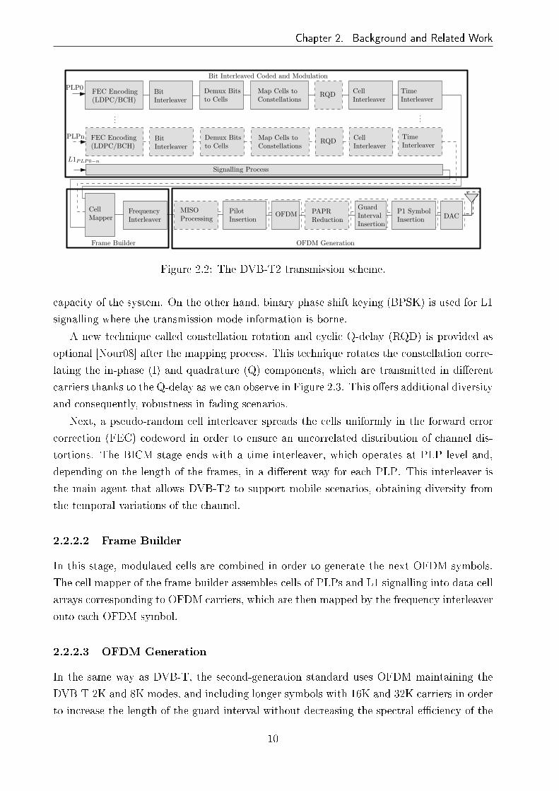
Chapter 2. Background and Related Work
......
PLP0
PLPn
L1PLP0−n
BitInterleaver
Demux Bitsto Cells
Map Cells toConstellations
RQD CellInterleaver
TimeInterleaver
BitInterleaver
Demux Bitsto Cells
Map Cells toConstellations
RQD CellInterleaver
TimeInterleaver
Signalling Process
CellMapper
FrequencyInterleaver
MISOProcessing
PilotInsertion
OFDM PAPRReduction
GuardIntervalInsertion
P1 SymbolInsertion
Bit Interleaved Coded and Modulation
Frame Builder OFDM Generation
FEC Encoding(LDPC/BCH)
FEC Encoding(LDPC/BCH)
DAC
Figure 2.2: The DVB-T2 transmission scheme.
capacity of the system. On the other hand, binary phase shift keying (BPSK) is used for L1
signalling where the transmission mode information is borne.
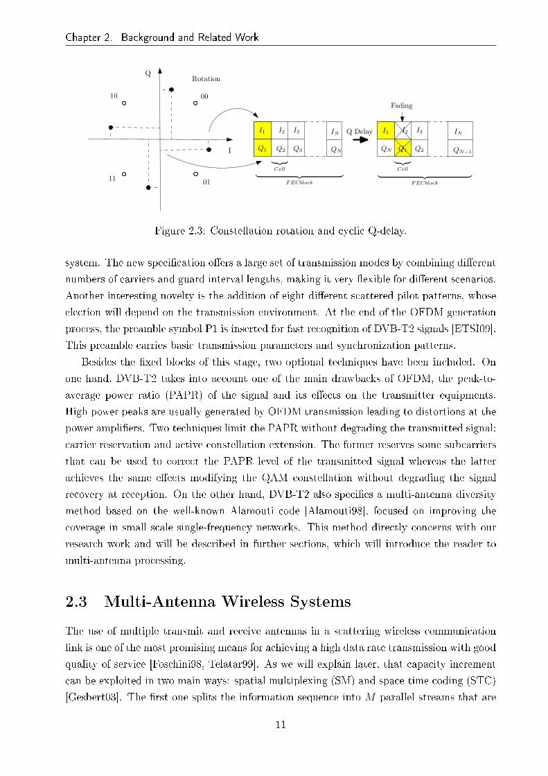
A new technique called constellation rotation and cyclic Q-delay (RQD) is provided as
optional [Nour08] after the mapping process. This technique rotates the constellation corre-
lating the in-phase (I) and quadrature (Q) components, which are transmitted in di�erent
carriers thanks to the Q-delay as we can observe in Figure 2.3. This o�ers additional diversity
and consequently, robustness in fading scenarios.
Next, a pseudo-random cell interleaver spreads the cells uniformly in the forward error
correction (FEC) codeword in order to ensure an uncorrelated distribution of channel dis-
tortions. The BICM stage ends with a time interleaver, which operates at PLP level and,
depending on the length of the frames, in a di�erent way for each PLP. This interleaver is
the main agent that allows DVB-T2 to support mobile scenarios, obtaining diversity from
the temporal variations of the channel.
2.2.2.2 Frame Builder
In this stage, modulated cells are combined in order to generate the next OFDM symbols.
The cell mapper of the frame builder assembles cells of PLPs and L1 signalling into data cell
arrays corresponding to OFDM carriers, which are then mapped by the frequency interleaver
onto each OFDM symbol.
2.2.2.3 OFDM Generation
In the same way as DVB-T, the second-generation standard uses OFDM maintaining the
DVB-T 2K and 8K modes, and including longer symbols with 16K and 32K carriers in order
to increase the length of the guard interval without decreasing the spectral e�ciency of the
10
Chapter 2. Background and Related Work
Q
I Q3Q2
I2 I3 IN
QN Q2
I2 I3 IN
QN QN−1
Q Delay
Rotation
Fading
I1
Q1 Q1
I1
0010
11 01︸ ︷︷ ︸
FECblock
︸ ︷︷ ︸FECblock
︸ ︷︷ ︸Cell
︸ ︷︷ ︸Cell
Figure 2.3: Constellation rotation and cyclic Q-delay.
system. The new speci�cation o�ers a large set of transmission modes by combining di�erent
numbers of carriers and guard interval lengths, making it very �exible for di�erent scenarios.
Another interesting novelty is the addition of eight di�erent scattered pilot patterns, whose
election will depend on the transmission environment. At the end of the OFDM generation
process, the preamble symbol P1 is inserted for fast recognition of DVB-T2 signals [ETSI09].
This preamble carries basic transmission parameters and synchronization patterns.
Besides the �xed blocks of this stage, two optional techniques have been included. On
one hand, DVB-T2 takes into account one of the main drawbacks of OFDM, the peak-to-
average power ratio (PAPR) of the signal and its e�ects on the transmitter equipments.
High power peaks are usually generated by OFDM transmission leading to distortions at the
power ampli�ers. Two techniques limit the PAPR without degrading the transmitted signal:
carrier reservation and active constellation extension. The former reserves some subcarriers
that can be used to correct the PAPR level of the transmitted signal whereas the latter
achieves the same e�ects modifying the QAM constellation without degrading the signal
recovery at reception. On the other hand, DVB-T2 also speci�es a multi-antenna diversity
method based on the well-known Alamouti code [Alamouti98], focused on improving the
coverage in small scale single-frequency networks. This method directly concerns with our
research work and will be described in further sections, which will introduce the reader to
multi-antenna processing.
2.3 Multi-Antenna Wireless Systems
The use of multiple transmit and receive antennas in a scattering wireless communication
link is one of the most promising means for achieving a high data rate transmission with good
quality of service [Foschini98, Telatar99]. As we will explain later, that capacity increment
can be exploited in two main ways: spatial multiplexing (SM) and space-time coding (STC)
[Gesbert03]. The �rst one splits the information sequence into M parallel streams that are
11

Chapter 2. Background and Related Work
transmitted independently from theM transmit antennas, maximizing the transmission rate,
whereas the second one uses the spatial and time domains to introduce redundancy. Thus,
transmission errors are minimized at the receiver exploiting the MIMO fading channel.
2.3.1 System and Channel Model
First of all, we de�ne a narrowband MIMO channel model as shown in Figure 2.4, which
depicts a wireless communication link with M transmit and N receive antennas. At each
time instant, M signals x1, . . . , xM are transmitted by M antennas satisfying an overall
transmit power constraint. Here, combinations of the transmitted signals are received at
each of the N antennas. If we consider a code length T that is shorter than the coherence
time1 TC of the channel, i.e. T < TC , we can rewrite the MIMO transmission model in
matrix form as
y11 . . . y1T
y21 . . . y2T
.... . .
...
yN1 . . . yNT
=
h11 . . . h1M
h21 . . . h2M
.... . .
...
hN1 . . . hNM
x11 . . . x1T
x21 . . . x2T
.... . .
...
xM1 . . . xMT
+
z11 . . . z1T
z21 . . . z2T
.... . .
...
zN1 . . . zNT
, (2.1)
which is equivalent to
Y = HX + Z, (2.2)
where H denotes the N ×M complex channel matrix whose coe�cient hij represents the
channel between transmit antenna j and receive antenna i, X is the M × T transmit signal
or codeword matrix, Z represents the independent and identically distributed (IID) additive
1Coherence time: the time interval over which the channel may be considered constant.
M transmitantennas
N receiveantennas
x1
xM
x2
y1
y2
z1
z2
zN
yN
h11
h12
hMN
h1NhM1
h21
h22
Transmitter Receiver
hM2
h2N
Channel H
Figure 2.4: MIMO channel with M transmit and N receive antennas.
12

Chapter 2. Background and Related Work
white Gaussian noise (AWGN) matrix with zero mean and variance per dimension σ2, i.e.
zij ∈ CN (0, 2σ2) 1 ≤ i ≤ N and 1 ≤ j ≤ T , and Y is the received signal matrix. Note that
each column of the matrix X is the vector x of symbols transmitted simultaneously by all
the transmit antennas; and each row corresponds to the signal transmitted by one antenna
over time. Performing coding across rows of X is considered spatial coding, whereas it is
referred to as time-domain coding when is carried out across columns. In other words, X
is considered the codeword of a space-time code formed by a linear combination of Q data
symbols where Q ≤ min(M,N)T . The channel matrix H and the transmitted signal matrix
X obey the power constraints
E[Tr(HHH
)]= MN and E
[Tr(XXH
)]= EsT = MT, (2.3)
where (·)H denotes conjugate transpose of a matrix and Tr (·) is the trace of a matrix. Note
that we have considered the average total transmitted energy per time instant as Es = M .
When we work with STC, Equation (2.2) is often rewritten for simplicity. This way,
our system can be rearranged as an equivalent NT ×MT MIMO channel where there is
no channel interference between the di�erent time slots t = 1, . . . , T . Thus, the equivalent
channel can be expressed as
H =
H1 0 . . . 0
0 H2 . . . 0...
.... . .
...
0 0 . . . HT
, (2.4)
where we have a block diagonal of channel realizations H t at time instants t = 1, . . . , T
and the o�-diagonal entries are zero matrices with dimensions N ×M . Note that we have
distinguished H t for t = 1, . . . , T since they are equal if and only if T < TC . In that case,
H t = H ∀t.Now, we restructure matrices X, Y and Z taking the elements column-wise into the
column vectors x = [x11, x21, . . . , xM−1T , xMT ]T , y = [y11, y21, . . . , yN−1T , yNT ]T and z =
[z11, z21, . . . , zN−1T , zNT ]T , respectively. Thus, if we consider that G is the complex code
generator matrix of the rearranged codeword x, (2.2) can be given as
y = HGs + z = Heqs + z, (2.5)
where HG forms the equivalent channel matrix Heq and s corresponds to the data symbol
column vector [s1, s2, . . . , sQ]T .
Finally, let us de�ne the average SNR of the wireless system per antenna and symbol
time as
13

Chapter 2. Background and Related Work
ρ =Es2σ2
. (2.6)
2.3.2 Channel Capacity
The channel capacity is the theoretical limit of the amount of data we can transmit through
a channel with reliability, i.e. with arbitrarily low error rate. This was �rst derived by
Shannon for a single antenna narrowband channel [Shannon48]. For such a system, the
channel capacity per Hz can be written as
CSISO = log2
(det(1 + ρ |h|2
))b/s/Hz, (2.7)
where det(·) denotes the determinant function and h is the complex single-input single-
output (SISO) channel.
For the capacity analysis of MIMO systems, we assume perfect channel knowledge at the
receiver. This assumption is sensible since training or pilot signals are always transmitted in
order to learn the channel in the DTV systems. In order to simplify notation, we consider
T = 1 and the transmitted signal as a column vector s. Hence, the capacity of a �at
deterministic MIMO channel is given by [Foschini96, Telatar99]
CMIMO = maxTr(Rss)=Es
log2
(det(IN +
ρ
MHRssH
H))
b/s/Hz, (2.8)
where IN is the identity matrix of dimensions N × N and Rss is the covariance matrix of
the transmitted signal s. The covariance matrix Rss must satisfy Tr(Rss) = Es in order to
constrain the total average energy transmitted over a symbol period, while s is assumed to
have zero mean [Paulraj03].
Given that our system's channel has no preferred direction and is completely unknown
to the transmitter, the best solution is to distribute the input power equally among the
transmit antennas, i.e. Rss = IM . Therefore, the channel capacity of (2.8) can be rewritten
as
CMIMO = log2
(det(IN +
ρ
MHHH
))b/s/Hz. (2.9)
If the channel was known at the transmitter side, it would be possible to choose a better
input distribution Rss and improve the channel capacity. Nevertheless, this is not the aim
of this research, since it is not possible in TDT broadcasting scenarios.
14

Chapter 2. Background and Related Work
2.3.3 Diversity-Multiplexing Trade-O�
The use of a MIMO channel can provide us of both data rate gain and increased robustness.
However, there is a trade-o� between these two types of gains; achieving more of one kind
requires sacri�ce of the other. This trade-o� was de�ned and analyzed in [Zheng03]. First of
all, we introduce the de�nition of diversity and multiplexing gains and then review the two
transmit and two receive antenna case, which is the most signi�cant case for our research.
For a given SNR ρ, let R (ρ) be the transmission data rate and Pe (ρ) the error probability
at that rate. Thus, the diversity gain d and the spatial multiplexing gain r are de�ned as
d = −lim supρ→∞
logPe (ρ)
log ρ, (2.10)
and
r = limρ→∞
R (ρ)
log ρ(2.11)
where sup denotes the supremum of the diversity advantage achieved over all the schemes
for each r.
Therefore, the diversity gain describes how fast error probability decays asymptotically
with SNR and will be directly related to the slope of the error probability curves. On the
other hand, multiplexing gain o�ers information about how fast the data rate grows with
SNR. The relation between these two parameters give us the diversity-multiplexing trade-o�
and can be used to evaluate and compare coding schemes.
In order to simplify calculation, [Zheng03] uses.= to denote exponential equality, such
that f(ρ).= ρb denotes
b = lim supρ→∞
log f (ρ)
log ρ. (2.12)
Thus, (2.10) can be written as
Pe (ρ).= ρ−d. (2.13)
With these de�nitions, we recall the main theorem of [Zheng03] for a system of M
transmit and N receive antennas:
Theorem 1 Assume T > M + N − 1. The optimal trade-o� curve dout(r) is given by
the piece-wise linear function connecting the points (k, dout(k)) , k = 0, . . . , K where K =
min (M,N) and
dout(k) = (M − k) (N − k) . (2.14)
Note that the trade-o� dout(r) is associated with the outage probability instead of the
error probability and, consequently, this is an upper bound of the optimal trade-o� achievable
15

Chapter 2. Background and Related Work
0 0.2 0.4 0.6 0.8 1 1.2 1.4 1.6 1.8 20
0.5
1
1.5
2
2.5
3
3.5
4
Multiplexing gain r
Div
eris
ity G
ain
d out(r)
Figure 2.5: Optimal diversity-multiplexing trade-o� curve for a two transmit and two receiveantenna transmission.
by any system. The diversity-multiplexing trade-o� dout(r) is represented in Figure 2.5 for
the case of two transmit and two receive antennas. We can observe that the maximum
diversity of this system is MN = 4 when r = 0, i.e. error probability decays with upper
bound ρ−4 when data rate is kept constant and, on the other hand, there is a multiplexing
gain of 2 b/s/Hz per 3 dB of SNR with zero diversity gain. Therefore, a bit rate increase of
2 bits leads to a shift of 3 dB in SNR for the same error probability.
In section 2.3.5, we present the diversity-multiplexing trade-o� curve for orthogonal space-
time block coding (OSTBC) and we see how this repetition code is sub-optimal.
2.3.4 Diversity Types
As has been stated, diversity is seen as how fast error probability decays and is represented
by the slope of the bit error rate (BER) curve at high SNR. Diversity is related to the
robustness of the system and depends on the number of transmit-receive antennas and the
information redundancy, which can be generated in many di�erent ways.
Di�erent criteria appear in the literature in order to enumerate kinds of diversity. Never-
theless, all of them follow a similar pattern, classifying them according to a main parameter
that represents the application area of the diversity. The three main criteria of classi�cation
are according to:
• The physical magnitude where the redundancy is generated.
• The algorithm which is used.
• The channel side, i.e. transmission or reception.
16

Chapter 2. Background and Related Work
Any of the options will be used in order to specify the diversity class throughout this
work. However, the classi�cation regarding the physical magnitude will be used in general
form to de�ne the diversity classes.
2.3.4.1 Spatial Diversity
As we have mentioned, diversity depends on the number of antennas at both transmitter
and receiver side. Therefore, the name of this kind of diversity comes from the own location
of the antennas. The di�erent subchannels between several transmit and receive antennas
allow to obtain di�erent observations of the same transmitted signal increasing the reliability
of the wireless link. If subchannels are uncorrelated to each other, they fade independently.
This allows to complement a faded signal with an enhanced one reducing the error rate in
reception. Several works have proved that the distance between antennas is directly related
to the subchannel correlation [Sanchez-Varela01]. Furthermore, it has to be longer than half
a wavelength in order to consider complete uncorrelation.
The selective combining (SC) [Rinne00] or equal gain combining (EGC) techniques are
some of the receive diversity methods that improve the reception quality. Nevertheless, the
technique known as maximum ratio combining (MRC) [Proakis95] is considered the best
solution at reception. Assuming perfect channel knowledge at the receiver, MRC combines
N received signals (independent faded versions of the same transmitted signal x) according
to
yMRC (t) =N∑
i=1
(M∑
j=1
hij (t)
)∗yi (t), (2.15)
where (·)∗ denotes complex conjugate. Thus, the post-processing SNR, ρMRC , is maximized
at the time instant t becoming
ρMRC =1
N
N∑
i=1
∣∣∣∣∣M∑
j=1
hij
∣∣∣∣∣
2
ρ. (2.16)
Most of MIMO techniques present spatial diversity gain and often exploit other dimension
in order to achieve more degrees of freedom. For instance, the techniques based on STC or
space-frequency coding (SFC), that are the most studied in DTV, combine spatial diversity
with time or frequency diversity, respectively.
2.3.4.2 Time Diversity
The information is sent repeatedly over time in such a way that each repetition is separated
by the coherence time TC in order to undergo di�erent fading channels. This redundancy
reduces the data rate and increases the latency of the system. Therefore, this kind of diversity
17

Chapter 2. Background and Related Work
is rarely used individually and is combined mainly with spatial diversity.
2.3.4.3 Frequency Diversity
In the case of frequency diversity, the same information is shared in di�erent carriers sep-
arated the coherence bandwidth2, BC . Its utilization is very common in frequency-division
multiplexing (FDM) systems where the frequency diversity is achieved through coding and
interleaving. Another example is the RQD technique of DVB-T2 (see Figure 2.3) that shares
correlated information of the I and Q components of a QAM symbol in di�erent carriers.
The frequency diversity can also be combined with multi-antenna processing through SFC
with the same methodology as STC.
2.3.4.4 Polarization Diversity
Polarization diversity is based on the signal transmission using antennas with di�erent polar-
ization (usually orthogonal polarization). The uncorrelation among di�erent polarized sig-
nals allows us to implement this multi-antenna technique in small devices without taking into
account the minimum antenna distance of half a wavelength. This technology has been widely
studied in DTV systems such as DVB-T [Sanchez-Varela00, Guena04, Corre05, Fluerasu05,
Mitchell06, Moss08] or Digital Video Broadcasting - Handheld (DVB-H) [ETSI04] for hand-
held terminals [Kyro07], and is currently an area of analysis [Gomez-Calero09] in the stan-
dardization process of the next generation of DVB-H, known as DVB-NGH.
2.3.4.5 Angular Diversity
This sort of diversity is related to the beam pattern of the antennas. The replicas of the
transmitted signal can undergo di�erent channels according to the main beams of the trans-
mit and/or receive antenna arrays. In this way, mechanisms such as scattering or re�ection
give rise to di�erent uncorrelated paths that allow the receiver to obtain diversity.
2.3.5 Space-Time and Space-Frequency Diversity Techniques
STC is an e�ective and practical way to approach the capacity of MIMO channels. Using
several transmit/receive antennas, they achieve transmit diversity without sacri�cing the
bandwidth. There are various coding schemes, having been some of them analyzed and
considered of interest for the development of broadcasting systems. Concretely, the well-
known Alamouti technique [Alamouti98] and some delay diversity schemes have been the
main candidates in last years. However, the inclusion of full rate STCs, which increase the
2Coherence bandwidth: the average frequency range over which channel can be considered �at, BC =
1TC
.
18
Chapter 2. Background and Related Work
data rate besides the diversity order, has recently taken more relevance in the standardization
process of future DTV systems [Nasser08c], as we will see in the ensuing section.
This section revises some pure diversity schemes studied in TDT systems. First o�, the
OSTBC structure for 2 × 1 and 2 × 2 antenna setups is analyzed. Later, we discuss space-
frequency block coding (SFBC) in OFDM systems and its equivalence to space-time block
coding (STBC). Finally, we conclude with a simple space-frequency diversity scheme called
cyclic delay diversity (CDD).
2.3.5.1 Orthogonal Space-Time Block Coding
The Alamouti code [Alamouti98] was the �rst OSTBC code, designed for two transmit
antennas and extended to more general cases in [Tarokh99]. OSTBC encodes a two symbol
vector s = [s1, s2] into a 2× 2 transmitted signal matrix X as follows:
Xal =
[s1 −s∗2s2 s∗1
]. (2.17)
Thus, the vector s is sent from two antennas (M = 2) in two time slots (T = 2). Any number
of receive antennas can be used. Nevertheless, we analyze the cases with N = 1 and 2, which
are the most interesting for the considered broadcasting scenarios.
2.3.5.1.1 One Receive Antenna Assuming that the channel is quasi-static for two
time slots, the resulting receive signal for N = 1 is
[y1 y2
]=[h1 h2
] [ s1 −s∗2s2 s∗1
]+[z1 z2
]. (2.18)
Rearranging terms, this can be rewritten as
[y1
y∗2
]=
[h1 h2
h∗2 −h∗1
]
︸ ︷︷ ︸Heq
[s1
s2
]+
[z1
z∗2
], (2.19)
where we have obtained an equivalent channel matrix Heq in the same way as in (2.5). The
column vectors of Heq are orthogonal to each other, so s1 and s2 can be decoupled, i.e. there
is no interference between them, and component-wise decoding can be easily done.
This scheme achieves the full channel capacity of a 2 × 1 system [Hassibi02]. However,
as we see later, this is not ful�lled for N > 1. On the other hand, OSTBC achieves the
maximum diversity, i.e. d = 2 for M = 2 and N = 1, according to the rank criterion for
STC in Rayleigh fading channels [Guey96, Tarokh98], that says:
Criterion 1 (Rank criterion): In order to achieve maximum diversity, the matrix ∆ =
19

Chapter 2. Background and Related Work
X − X has to be full rank for any codewords X and X. Then, the code is said to have full
diversity. Otherwise, a diversity gain of Nκ is achieved being κ, the rank of ∆.
The rank criterion and the determinant criterion, which will be analyzed later, are rele-
vant in order to maximize the gain of STC codes.
2.3.5.1.2 Two Receive Antennas For the case of M = 2 and N = 2, the resulting
receive signal is
[y11 y12
y21 y22
]=
[h11 h12
h21 h22
][s1 −s∗2s2 s∗1
]+
[z11 z12
z21 z22
], (2.20)
which can be rewritten as
y11
y21
y∗12
y∗22
=
h11 h12
h21 h22
h∗12 −h∗11
h∗22 −h∗21
︸ ︷︷ ︸Heq
[s1
s2
]+
z11
z21
z∗12
z∗22
, (2.21)
where the orthogonality of the column vectors of Heq is maintained. Therefore, low com-
plexity decoding can also be done.
Using (2.8), the capacity of this system can be given as
COSTBC (ρ) = maxTr(Rss)=2
1
2log2
(det(I2 +
ρ
2HeqRssH
Heq
))
= maxTr(Rss)=2
1
2log2
(det(I2 +
ρ
2HH
eqHeqRss
)), (2.22)
where the factor 12before the logarithm normalizes the extended equivalent channel Heq due
to the orthogonal design [Hassibi02]. Considering no channel information at the transmitter,
i.e. Rss = I2, Equation (2.22) becomes
COSTBC (ρ) = maxTr(Rss)=2
1
2log2
(det(I2 +
ρ
2
(|h11|2 + |h21|2 + |h12|2 + |h22|2
)I2
))
= log2
(1 +
2ρ
4
(|h11|2 + |h21|2 + |h12|2 + |h22|2
))
= C (2ρ,M = 4, N = 1)
< C (ρ,M = 2, N = 2) . (2.23)
The inequality in (2.23) implies that OSTBC does not reach the full channel capacity of
a system with M = 2 and N = 2 but rather the capacity of a system with M = 4, N = 1
20

Chapter 2. Background and Related Work
0 0.2 0.4 0.6 0.8 1 1.2 1.4 1.6 1.8 20
0.5
1
1.5
2
2.5
3
3.5
4
Multiplexing gain r
Div
ersi
ty g
ain
d out(r)
optimalOSTBC
Figure 2.6: Comparison of optimal diversity-multiplexing trade-o� curve and diversity-multiplexing trade-o� achieved by OSTBC for two transmit and two receive antennas.
and doubled SNR. Although OSTBC does not achieve full channel capacity, this scheme is
one of the most extended STC in wireless communication systems due to its low decoding
complexity based on linear detection techniques.
If we examine the diversity-multiplexing trade-o� of OSTBC with M = 2 and N = 2, we
can see that, as for the previous case, it achieves the maximum diversity of MN = 4 when
r = 0. Nevertheless, due to the code redundancy, only one new symbol is transmitted at
each time slot and thus, it can only achieve r = 1 when d = 0 [Zheng03]. Therefore, as it
can be seen in Figure 2.6, OSTBC does not provide optimal diversity-multiplexing trade-o�
and high SNR is essential for high data rate.
We now show below some of the simplest decoding and detection algorithms that can be
used to decode OSTBC transmissions.
2.3.5.1.3 Linear Detection Techniques Due to the property of orthogonality, we have
seen that symbols s1 and s2 of OSTBC are decoupled in (2.19) and (2.21). Therefore, they
can be detected independently with an equivalent MRC [Alamouti98]. However, variations of
channel throughout the transmission of X lead to a loss of orthogonality and consequently, a
coupling between the symbols to be detected. Other low complexity decoding techniques can
be used that do not require the orthogonality property. The simplest detection algorithms
are the linear techniques, where the detected symbol vector s is obtained by multiplying the
received signal y in (2.5) by an equalization matrix C as follows
21
Chapter 2. Background and Related Work
s = Cy. (2.24)
The two most common algorithms are the following:
1. zero forcing (ZF): the elimination of the intersymbol interference requires the use
of a channel-inverting �lter, which is given by
CZF = H†eq =
(HH
eqHeq
)−1HH
eq, (2.25)
where (·)† denotes the pseudoinverse matrix. If Heq is invertible, then CZF = H−1eq .
This method is the easiest to implement but it has a limited performance due to the
noise enhancement.
2. minimum mean squared error (MMSE): This method minimizes the overall error
taking into account the SNR for the calculation of the �lter matrix C and thus, the
noise enhancement is reduced. The matrix CMMSE is obtained according to
CMMSE =
(HH
eqHeq +M
ρIM
)−1
HHeq. (2.26)
2.3.5.2 Space-Frequency Block Coding
When systems are based on multi-carrier modulation schemes such as OFDM, coding is car-
ried out in space and frequency domains. Since OFDM converts frequency-selective channels
into multiple �at fading channels, the detection is simpli�ed in the frequency domain, where
the received signal is simply the product between the channel and the transmitted signal plus
the noise term as in (2.2). Hence, codewords are fed into carriers of OFDM symbols which
are transformed later to the time domain through the inverse fast Fourier transform (IFFT).
At the receiver, the opposite process is carried out; the received signal is captured in time
domain and is transformed to the frequency domain through fast Fourier transform (FFT)
before being detected.
When the codeword is transmitted at the same carrier of several consecutive OFDM sym-
bols, it is named STBC or STBC-OFDM [Lu00]. On the other hand, if the codeword is trans-
mitted combining adjacent carriers of one OFDM symbol, it is named SFBC [Bolcskei00].
This technique has been adopted by the DVB-T2 standard [ETSI09] as an optional diversity
transmission scheme. As we can observe in Figure 2.7, the DVB-T2 multiple-input single-
output (MISO) model employs two antennas to transmit the Alamouti code [Alamouti98]
across OFDM carriers. Although Alamouti code has been chosen as the MISO code for
DVB-T2, any other STC scheme may be implemented in the same way.
22

Chapter 2. Background and Related Work
Both OFDM symbols are transmitted
sinchronously
Payload cells within an OFDM symbol
(Frequency axis)
...
...
...
...
SFBC OFDM
SFN Transmitter 1 s
1s
3s
5s
7s2
s4
s6
s8
-s2
* s1
* s3
* s5
* s7
*
Encoding process is done on pairs of OFDM payload cells
DataCells
...s1s
2s
3s
4...
SFN Transmitter 2
-s4
* -s6
* -s8
*
Figure 2.7: SFBC transmission scheme of DVB-T2 system.
If we pay attention to the MISO scheme of Figure 2.7, one should note that the codeword
of (2.17) is slightly modi�ed such that it is now expressed as
Xal =
[s1 s2
−s∗2 s∗1
], (2.27)
whose equivalent channel matrix is given by
Heq =
[h1 −h2
h∗2 h∗1
]. (2.28)
2.3.5.3 Cyclic Delay Diversity
This spatial and frequency diversity technique is a variation of the delay diversity (DD)
scheme [Wittneben93] which was �rst adapted to OFDM systems in [Kaiser00] as phase
diversity (PD) and later in [Dammann01] as CDD. In the DD method shown in Figure
2.8(a), the transmitted signal is identical for all transmit antennas, di�ering in a delay
added per each antenna after the GI insertion. This simple technique generates an arti�cial
multipath environment similar to an echo channel that achieves frequency selectivity of the
signal spectrum at the receiver. The disadvantage of DD is that if the additional delays
are longer than the GI, this can cause intersymbol interference and requires an extension of
GI, reducing the bandwidth e�ciency of the system. In contrast, CDD or its equivalent PD
prevent such bandwidth e�ciency reduction by using cyclic signal shifts δ before GI insertion
or phase shifts in frequency domain before IFFT, respectively. Figure 2.8(b) depicts the CDD
scheme. The equivalence between CDD and PD is due to the periodicity property of the
discrete Fourier transform as we can see in the following equation:
23

Chapter 2. Background and Related Work
OFDM Guard IntervalInsertion δ1
δM−1DAC
DAC
DAC
(a) DD
Guard IntervalInsertion
δ1
δM−1
Guard IntervalInsertion
Guard IntervalInsertion
DAC
DAC
DAC
IFFT
(b) CDD
Figure 2.8: Schemes of delay diversity and cyclic delay diversity.
s((t− δ)modNFFT )︸ ︷︷ ︸CDD
=1√NFFT
NFFT−1∑
f=0
e−i 2πfδ
NFFT S(f)︸ ︷︷ ︸PD
ei 2πftNFFT , (2.29)
where NFFT , t, f, s (t) and S (f) are number of carriers, discrete time, frequency and complex
symbols in time and frequency domain, respectively.
The inclusion of CDD has been widely analyzed for di�erent terrestrial DTV systems.
For instance, in [Dammann01] for DVB-T and in [Dammann09] for DVB-T2, this diversity
scheme has been assessed and compared to other techniques. On the other hand, CDD has
also been tested over di�erent channel models; in [Dammann07] this method is analyzed
over Ricean channels for DVB-T and in [Zhang07], the same scheme is studied for spatial
correlated channels for DVB-H. Regarding the deployment of networks, �eld measurements
for DVB-T are presented in [Di Bari08, Di Bari09] and coverage analysis for DVB-H in
[Zhang08].
2.3.6 Full-Rate Full-Diversity Techniques
So far we have focused on techniques regarding one of the bene�ts of MIMO systems, i.e.
diversity. As we have seen in Section 2.3.3, this advantage results in robustness, in words
of one syllable, reducing the error probability for a given SNR. Nonetheless, the drawback
of the aforementioned diversity techniques is that they do not exploit spatial multiplexing,
since such con�gurations preserve the SISO data rate. Consequently, they do not reach the
MIMO diversity-multiplexing trade-o� frontier. In this aspect, there exist multiple schemes
[Tirkkonen00, Hassibi02, Ma03, Yao03] that combine those two interesting MIMO features.
Hence, this section analyzes those full-rate full-diversity (FRFD) techniques that can be used
in future terrestrial DTV systems.
Before starting with the review of FRFD techniques, we will comment some criteria that
optimize the FRFD STC design. As we have seen in previous sections, STC must ful�ll the
rank criterion in order to achieve full diversity (see Criterion 1). In addition to this rule,
which was derived in [Guey96, Tarokh98], Tarokh et al. presented in [Tarokh98] another
criterion to maximize the coding gain based on the Cherno� bound analysis of pairwise error
24
Chapter 2. Background and Related Work
probability (PEP) P (X → X), which is the probability of transmitting X and detecting
X at the receiver. The minimization of PEP for Rayleigh fading channels leads to the next
criterion:
Criterion 2 (Determinant criterion): In order to obtain maximum coding gain, the mini-
mum of the determinants of the matrices ∆H∆ has to be maximized for all pairs of di�erent
codewords X and X.
According to Hassibi et al. [Hassibi02], X can be rewritten as
X =
Q∑
q=1
(<{sq}Aq + ={sq}Bq), (2.30)
when STC is considered a linear dispersion (LD) code, being Aq and Bq for q = 1, . . . , Q
the dispersion matrices. Then, the design optimization of X has to be subject to one of the
following three power constraints [Hassibi02]:
Q∑
q=1
(Tr(AHq Aq
)+ Tr
(BHq Bq
))= 2TEs, (2.31)
Tr(AHq Aq
)= Tr
(BHq Bq
)=TEsQ
, q = 1, . . . , Q, (2.32)
AHq Aq = BH
q Bq =T
QIM , q = 1, . . . , Q. (2.33)
After recalling these main criteria for STC design, we review some FRFD codes which
are interesting for the considered terrestrial DTV scenarios.
2.3.6.1 The Golden Code
The Golden code is the FRFD 2×2 STC which achieves the maximal coding gain [Bel�ore04].
It encodes a group of four symbols s = (s1, s2, s3, s4) which are transmitted as follows:
Xg =1√5
[α (s1 + θs3) α (s2 + θs4)
iα(s2 + θs4
)α(s1 + θs3
)], (2.34)
with θ = 1+√
52
(the golden number), θ = 1−√
52
, α = 1 + i (1− θ) and α = 1 + i(1− θ
).
This code ful�lls the power conditions of (2.31) and (2.32), which ensure that the average
transmit power corresponds to (2.3), i.e. E[Tr(XgX
Hg
)]= MT , and that each of the
transmitted signals xij are transmitted with the same overall power from the M antennas
during the T channel uses, respectively. However, it does not obey (2.33) which involves
that the symbols are dispersed with equal energy in all spatial and temporal directions.
25
Chapter 2. Background and Related Work
The main drawback of the Golden code lies on the decoding complexity. In order to
choose a detected vector s, we need to perform an exhaustive search for all symbol vectors
s = (s1, s2, s3, s4) which form the codeword Xg. This search is carried out by a maximum
likelihood (ML) detector and, as we will see later, the complexity of the ML algorithm is
exponential in the length of the symbol vector s, i.e. O(P 4), which is prohibitive for large
constellation sizes P . Note that we have de�ned O(·) in order to quantify the detection
complexity such that O(P 4) denotes a variable complexity upper-bounded by P 4.
2.3.6.2 Low Complexity Codes
The following STC schemes are designed in such a way that they ful�ll the aforementioned
STC design criteria and allow us to perform optimum detection with lower complexity.
Although this sort of STC �rst appeared in [Tirkkonen02], their low-complexity detection
property was not analyzed until [Sezginer07, Paredes07]. Despite their coding gains are lower
than Golden coding gain, their reduced complexity makes them feasible candidates if MIMO
techniques are considered in future broadcasting TV systems.
2.3.6.2.1 The Silver Code This 2×2 STBC code exploits the properties of the OSTBC
generator matrix in order to reduce the ML decoding complexity [Paredes07, Paredes08].
This STC code belongs to the class of linear dispersion codes [Hassibi02] so they can be
written as (2.30). If we rearrange the real and imaginary parts of the symbol vector s =
[s1, s2, s3, s4]T in a real-valued column vector as
sR = [<{s1} ,={s1} ,<{s2} , . . . ,={s4}] , (2.35)
and we do the same with the codeword X such that the column vector x = [x11, x21, x12, x22]T
is expressed as (2.35), X can be then written as xR = GRsR, where GR is the real-valued
code generator matrix of the STC, which is de�ned as
GR =1√14
√7 0 0 0 −1 1 1 2
0√
7 0 0 1 −2 1 1
0 0√
7 0 1 1 2 −1
0 0 0√
7 2 1 −1 1
0 0 −√
7 0 1 1 2 −1
0 0 0√
7 −2 −1 1 −1√7 0 0 0 1 −1 −1 −2
0 −√
7 0 0 1 −2 1 1
. (2.36)
As it is proved in [Paredes08], the detection complexity can be reduced using ML detection
26
Chapter 2. Background and Related Work
for two symbols of s and symbol-by-symbol detection for the other two, thus achieving a
complexity order of O(P 2) + P .
2.3.6.2.2 The Sezginer-Sari Code This 2×2 SFBC scheme was designed so as to allow
for optimum detection with a lower complexity than the Golden code. The main di�erence
between the SS [Sezginer07] and the Silver code [Paredes07] is the larger coding gain of the
Silver code.
The SS code consists of a combination of two Alamouti schemes and can be described as
follows:
XSS =
[as1 + bs3 as2 + bs4
−cs∗2 − ds∗4 cs∗1 + ds∗3
], (2.37)
with a = c = 1/√
2, b =1−√
7+i(1+√
7)4√
2and d = −ib. These scalars are chosen so as to
ful�ll the STC design criteria following the power constraints of (2.31), (2.32) and (2.33). In
[Sezginer07] it is proved that optimum detection is reached with a symbol-by-symbol detector
with complexity P plus an ML detector with complexity O(P 2). This can be further reduced
by means of a sphere decoder [Sezginer09]. However, it must be taken into account that the
sphere decoder complexity, which is variable, is also upper-bounded by O(P 2).
2.3.6.3 Detection Techniques
When orthogonal codes are used, MIMO detection can be considered as a set of parallel
SISO detection problems, so it can be simpli�ed using linear techniques such as ZF or MMSE
[Paulraj03]. However, when spatial multiplexing is added to the spatial coding, non-linear
detection algorithms have to be used since linear techniques reduce the diversity order in
the system performance [Paulraj03]. The most common and interesting algorithms for the
detection of the aforementioned FRFR codes are shown below.
2.3.6.3.1 Optimal Maximum Likelihood Detection The ML detector is considered
the optimal detector since it minimizes the probability of error [Proakis95]. It chooses the
transmitted symbol vector that solves
sml = arg mins∈M‖y −Heqs‖2 , (2.38)
performing an exhaustive search over all symbol vectors s which form the codeword X.
The complexity of computing sml is exponential in the length of the symbol vector s. In
the case of the reviewed FRFD codes, this is O(P 4), which becomes prohibitive for large
constellation orders. The detection complexity can be reduced by means of the sphere
decoder (SD) algorithm whose complexity can be considered to be polynomial for moderate
27

Chapter 2. Background and Related Work
numbers of antennas and constellation orders [Hassibi05], maintaining the ML performance.
This algorithm is explained in detail below.
2.3.6.3.2 Sphere Decoding The SD algorithm is based on the underlying lattice struc-
ture of the received signal [Viterbo93]. The main purpose is to reduce the complexity of the
ML detector by searching over only those noiseless received points, de�ned as Heqs, that
lie within a hypersphere of radius R around the received signal y, instead of searching over
the entire lattice. The basic principle is shown in Figure 2.9 with a simpli�ed 2-dimensional
case, where the black dots represent the noiseless received constellation or lattice and the
center of the circle is the noisy received point.
The process can be described as
sml = arg mins∈M‖y −Heqs‖2 ≤ R2, (2.39)
The Euclidean distance calculation in (2.39) can be also written as
‖y −Heqs‖2 = ‖Heq (s− s)‖2 +∥∥(INT −HeqH
†eq
)y∥∥2, (2.40)
where s = H†eqy is the unconstrained least squares estimate or Babai point [Hassibi05]. It
can be observed that the second term in (2.40) is constant so it can be discarded for solving
(2.39). Moreover, the sphere constraint in (2.40) can be rewritten as
‖U (s− s)‖2 ≤ R2, (2.41)
where U is anMT×MT upper triangular matrix whose coe�cients uij are obtained through
the Cholesky decomposition of the Gram matrix HHeqHeq or, equivalently, QR decomposition
of Heq.
The solution of the sphere constraint in (2.41) can be obtained recursively using a tree
search algorithm. Given the triangular structure of U , it is now possible to work up to level
i recursively by traversing the tree backwards from level i = MT to i = 1. For each level,
R
Figure 2.9: Schematic of the sphere decoder search principle for the 2-dimensional case.
28
Chapter 2. Background and Related Work
the constellation points si that satisfy
|si − zi|2 ≤Tiu2ii
, (2.42)
are selected as partial ML candidates, where
zi = si −MT∑
j=i+1
uijuii
(sj − sj), (2.43)
and
Ti = R2 −MT∑
j=i+1
ujj |sj − zj| . (2.44)
When a new vector is found inside the hypersphere (at i = 1) the radius is updated with the
new minimum Euclidean distance and the algorithm continues the search. This process can
be seen as a tree search through MT levels where each node contains P branches. When
Ti ≤ 0 in any level i, the accumulated (squared) Euclidean distance (AED) from the root to
that node has exceeded the sphere constraint and the entire branch plus all its descendants
can be then discarded, yielding a speed increase compared to an exhaustive search. The
search �nishes when the radius has been reduced so that no more points are found inside
the hypersphere, being the last point found satisfying the sphere constraint the ML solution
sml.
There exist two di�erent methods to de�ne the order in which the points si are visited
at each level:
• Fincke-Pohst (FP) enumeration: the points are visited in an arbitrary constella-
tion order [Fincke85]. In this enumeration, the complexity of the SD is mainly deter-
mined by the radius R. The initial radius is chosen according to the noise variance
per antenna [Hochwald03]. If no vectors are found inside the hypersphere, the radius
would need to be increased and the detector would need to be run again.
• Schnorr-Euchner (SE) enumeration: in this case, the points are visited according
to increasing distances to zi [Schnorr91]. This way, the probability of �nding the ML
solution among the �rst vectors searched is incremented reducing the overall complexity
of the algorithm. The initial value can be set to the end of the scale so that no estimate
of the noise level is required at the receiver. However, from a simulation point of
view, the initial radius still has a marginal e�ect on the complexity of the algorithm
[Damen03].
29
Chapter 2. Background and Related Work
2.4 Chapter Summary
This chapter has reviewed the two main aspects involved in this work. First, the evolution
of the European DTV broadcasting standards is summarized, making a brief description of
their technical key features. From the DVB-T2 standard to its predecessor DVB-T, there has
been a radical change in the physical layer resulting in an increase of the system capacity and
robustness. The improvement of DVB-T2 is based on the inclusion of new coding schemes,
higher number of interleavers, high modulation orders and several optional techniques such
as pilot patterns, RQD or MISO.
The second part of the chapter deals with the multi-antenna processing aimed at the
TDT systems. As a starting point, a MIMO wireless system model has been de�ned. Next,
a theoretical review of the potential bene�ts of MIMO channels has been provided, focusing
on spatial multiplexing and speci�cally, on diversity. Due to the great variety of diversity
techniques, a classi�cation of the di�erent kinds has been presented paying attention to
those schemes used in DTV. The techniques which combine spatial with time or frequency
diversity such as SFBCs, have been explained in more detail since they might become a
future MIMO alternative for next generation DTV systems. A clear example is the inclusion
in DVB-T2 of an optional MISO SFBC technique based on the Alamouti scheme. Although
this technique o�ers higher robustness at the receiver, it does not fully exploit the MIMO
channel properties. For that purpose, the FRFD SFBC codes are one of the most attractive
possibilities for the future, because they combine spatial multiplexing and diversity getting
closer to the diversity-multiplexing frontier. The last part of the chapter has shown the
most interesting proposals which may be implemented in TDT networks and has reviewed
the detection algorithms required for their e�cient hardware implementation.
30
Chapter 3
Multi-Antenna Diversity Schemes in
DVB-T and DVB-T2 Broadcasting
3.1 Introduction
The wide range of propagation conditions in TDT networks involves a robust and �exible
physical layer in DTV standards. In order to adapt them to all possible scenarios, which
can range from a strong direct component to a severe multipath channel with deep fadings,
DTV standards, such as DVB-T or DVB-T2, include redundancy through channel coding.
These systems are mainly based on a BICM scheme which combines coding, interleaving and
modulation. When reception is given at low SNR, low code rates are necessary, resulting in
a loss of throughput e�ciency. Nonetheless, a solution that increases the performance while
maintaining the same reception quality can be obtained based on MIMO processing.
This chapter provides a simulation analysis of diversity schemes for multiple TDT sce-
narios in both DVB-T and DVB-T2 systems. On one hand, we assess the state-of-the-art
multi-antenna diversity techniques, such as the Alamouti code or CDD, in the DVB-T stan-
dard. On the other hand, we observe the behavior of the optional diversity techniques of
DVB-T2, such as RQD and the MISO SFBC scheme.
Moreover, the inclusion of the optional SFBC technique in DVB-T2 gives rise to a new
concept of transmission over single frequency networks (SFNs), called distributed MISO. In
a typical MISO scheme, the transmit antennas are usually located at the same base station
or transmitter. However, within the SFN network, each transmitter can be considered as
one antenna in such a way that the MISO system is formed by various transmitters of the
network and the receive antenna. This way, a di�erent channel model has to be de�ned and
the behavior of the system will also depend on the deployment of the network.
At the �rst part of the chapter the broadcasting channel models used throughout the
thesis are de�ned. Next, we will see the behavior of diversity techniques over di�erent
reception environments in the DVB-T and DVB-T2 systems. Finally, the last section presents
the advantages and disadvantages of the SFN deployment, both with and without multi-
31

Chapter 3. Multi-Antenna Diversity Schemes in DVB-T and DVB-T2 Broadcasting
antenna processing.
3.2 Fading Channels
The characterization of TDT channels is essential for the analysis of diversity schemes. DVB-
T is a broadcasting system which can form either a multiple frequency network (MFN) or
an SFN. The transmitters of the network are usually stationary and the reception can take
place in very di�erent scenarios: urban, rural, indoor, mobile, etc. As a result, various
mathematical models with di�erent statistical properties are necessary according to the
propagation conditions.
Due to the re�ections of transmitted waves from buildings, ground or other obstacles,
multiple replicas of the transmitted signal arrive at the receiver. This e�ect is known as
multipath propagation. If the maximum path delay is longer than the symbol period, the
channel is said to be frequency selective and the longer the di�erence, the more selective
the channel is, involving more and deeper fadings in the frequency domain. Rayleigh and
Rice distributions are the most common statistical processes for characterizing the multipath
propagation [Patzold02].
As we have mentioned, the DTV transmission can be deployed over MFN or SFN. The
MFN corresponds to the typical analogue TV transmission systems where every transmitter
of the network uses a di�erent carrier frequency in order to transmit the same information.
With the deployment of an SFN, all the transmitters broadcast the same program syn-
chronously at the same carrier frequency. This means that the TV signal is transmitted at
the same frequency covering the whole area of the network, which can be formed by multiple
transmitters. This allows an e�cient use of the radio spectrum, yielding a higher number
of TV programs compared to MFN. Therefore, the SFN model represents the multipath
propagation from two or more transmitters of the network in such a way that the distances
from transmitters to the receiver are taken into account.
3.2.1 Rayleigh and Ricean Channels
The sum of all multipath gains of the transmitted signal can be described in the equiva-
lent complex baseband as a zero-mean complex Gaussian random process if we consider a
frequency-non-selective or �at fading channel
µ(t) = µ1(t) + iµ2(t), (3.1)
where the real-valued Gaussian random processes µ1(t) and µ2(t) are assumed statistically
uncorrelated corresponding to CN (0, σ2) each. Thus, the variance of µ(t) is given by 2σ2.
32

Chapter 3. Multi-Antenna Diversity Schemes in DVB-T and DVB-T2 Broadcasting
The envelope of (3.1), which is given by the absolute value |µ(t)|, follows a Rayleigh distri-
bution.
If there is a line-of-sight (LOS) component in the received signal, the new component
can be described as m(t) = m1(t) + im2(t) with mean value m. At the receiver antenna, the
received signal µρ(t) is the superposition of the scattered and the LOS component such that
µρ(t) = µρ1(t) + iµρ2(t) = µ(t) +m(t), (3.2)
where the envelope |µρ(t)| is now a Ricean distribution. Note that we have taken into
account the time variable in all equations in order to represent both stationary and mobile
environments.
So as to model the mobile channels, we have used a real-valued coloured Gaussian random
process called the Rice method. The procedure consists of the generation of a Gaussian
deterministic process µi from the superposition of a �nite number Ni of harmonic functions
with di�erent weights ci,n, equidistant frequencies fi,n and random phases θi,n with uniform
distribution [Patzold02]. The generated channel for i = 1, 2 can be described mathematically
as
µi(t) =
Ni∑
n=1
ci,ncos(2πfi,nt+ θi,n), (3.3)
where ci,n, fi,n y θi,n are the Doppler coe�cients, discrete frequencies and phases, respectively,
calculated from the Doppler power spectral densities. For a process µ(t), the power spectral
density Sµµ can be separated as Sµµ = Sµ1µ1 + Sµ2µ2 following (3.1). By modelling the
mobile channel, we frequently simplify matters. Thus, assuming that the propagation of
electromagnetic waves occurs in a two-dimensional plane, the angles of incidence of the
waves are uniformly distributed from 0 to 2π and the receive antenna is omnidirectional, one
�nds the expression �rst derived by [Clarke89] and named Jakes spectrum [Jakes94] for the
Doppler power spectral density Sµµ of a �at fading channel µ(t) as
Sµiµi =σ2
πfmax√
1− (f/fmax)2|f | ≤ fmax, (3.4)
where i = 1, 2 and fmax denotes the maximum Doppler frequency.
It has been proved that the Doppler power spectral density of the far echoes deviates
considerably from the shape of the Jakes expression [Cox73], which is approximately Gaus-
sian shaped and can be mathematically represented by the so-called Gaussian power spectral
density
Sµiµi =σ2
fc
√ln2
πe−ln2( f
fc)2 , (3.5)
33

Chapter 3. Multi-Antenna Diversity Schemes in DVB-T and DVB-T2 Broadcasting
where fc denotes the 3-dB-cut-o� frequency. The Gaussian power spectral densities are
generally shifted from the origin of the frequency plane because far echoes mostly dominate
from a certain direction of preference.
Finally, assuming a wide-sense stationary uncorrelated scattering (WSSUS) channel ac-
cording to [Bello63, Hoeher92], a representation of a frequency-selective and time-variant
SISO channel in the equivalent complex baseband can be given by a sum of a �nite number
L of taps as
h(τ, t) =L−1∑
l=0
alµl(t)δ(τ − τl), (3.6)
where al and τl are the tap coe�cients and delays, respectively. It is noteworthy that
(3.6) is the instantaneous channel impulse response (CIR) of the channel and each path is
characterized by an independent and uncorrelated process, µl = µ1,l + iµ2,l. For a MIMO
channel, there are as many CIR as subchannels, i.e. MN , and the corresponding translation
of (3.6) to each OFDM carrier would correspond to the entries of the channel matrix H in
(2.2).
In order to measure the multipath degree of the channel, let us de�ne the delay spread
as
τrms =
√√√√√√√√√√
L−1∑
l=0
(τl − τ)2 alµl(t)
L−1∑
l=0
alµl(t)
, (3.7)
where τ is the mean delay of the channel, expressed as
τ =
L−1∑
l=0
τlalµl(t)
L−1∑
l=0
alµl(t)
. (3.8)
3.2.2 Multipath Channel Models
Radio channel models are usually derived from �eld measurements of the channel parameters
in reference scenarios. This allows us to create realistic models according to the reception
environment under study (e.g. outdoor, indoor, rooftop, etc.). In TDT, due to the variety
of scenarios, multiple models have been used to assess the performance at the receiver. TDT
standards, such as DVB-T or DVB-T2, de�ne several channel models to provide simulated
performance results. However, some of them are not realistic and should be used only for
34
Chapter 3. Multi-Antenna Diversity Schemes in DVB-T and DVB-T2 Broadcasting
checking and veri�cation tasks. For instance, some of them are considered as a snapshot of a
real channel and they do not include Doppler parameters. In that case, one channel realiza-
tion is only used for the assessment of the system providing probably optimistic performance
results. The DVB-T speci�cation [ETSI97] de�nes two channel models which describe �xed
(F1) and portable (P1) reception. In addition to the DVB-T channels, the DVB-T2 imple-
mentation guidelines document [DVB09] includes a higher number of channel models that
cover a wide range of reception conditions. Besides the channels presented for DVB-T and
DVB-T2, there also exist several research projects where other models have been developed
to simulate and analyze the performance of the DTV systems. The list below shows the
most common channels used in the literature including the mentioned DVB-T and DVB-T2
channels.
1. DVB-T channels [ETSI97]
(a) Rayleigh P1 (20 paths).
(b) Rayleigh P1 approximation (6 paths)[EVS06].
(c) Ricean F1 (21 paths).
2. DVB-T2 channels [DVB09]
(a) DVB-T P1 and F1.
(b) Mobile Channel-Typical Urban channel (6 paths) (TU6).
(c) Simple two path pro�le, 0 dB echo.
(d) MISO channels: Ricean and Rayleigh.
(e) Memoryless Rayleigh channel with erasures.
3. COST1 207 channels[COST20789]:
(a) Typical Urban channel (12 paths) (TU12).
(b) TU6.
(c) Rural Area channel (6 paths) (RA6).
(d) Bad Urban channel (6 paths) (BA6).
4. Eureka Celtic Wing TV project channels [ITU06, Hakala07]:
(a) Pedestrian Indoor channel (PI).
(b) Pedestrian Outdoor channel (PO).
1COST: European Cooperation in the Field of Scienti�c and Technical Research.
35
Chapter 3. Multi-Antenna Diversity Schemes in DVB-T and DVB-T2 Broadcasting
Type Doppler power spectral density Sµµ(f)
Jakes 1
πfmax√
1−(f/fmax)2
Gauss 1 503√
2πfmaxe− (f+0.8fmax)2
2(0.05fmax)2 + 53√
2πfmaxe− (f−0.4fmax)2
2(0.1fmax)2
Gauss 2 10√
10√2π(√
10+0.15)fmaxe− (f−0.7fmax)2
2(0.1fmax)2 + 1√2π(√
10+0.15)fmaxe− (f+0.4fmax)2
2(0.15fmax)2
Rice 0.412
πfmax√
1−(f/fmax)2+ 0.912δ(f − 0.7fmax)
Table 3.1: Speci�cation of Doppler power spectral densities according to the COST 207project.
5. Channels used in Pluto project [ist07]:
(a) Outdoor Residential-High Antenna (Channel B) [JTC93].
(b) Indoor Commercial (Channel B) [JTC93].
In this work, we have chosen some of the mentioned channel models in order to study and
analyze the multi-antenna diversity techniques and the corresponding detection algorithms
paying special attention to the COST 207 TU6 and RA6 channels [COST20789].
3.2.2.1 TU6 and RA6 Channels
TU6 and RA6 channel models were �rst developed for Global System for Mobile Commu-
nications (GSM) systems. Nonetheless, some channel pro�les from [COST20789], such as
TU6 and RA6, were adapted to mobile DVB-T due to similar propagation conditions of
GSM and TDT systems [Motivate00]. In fact, the TU6 channel has been included in the
DVB-T2 speci�cations [DVB09] and it is one of the most extended models for simulation
tests in DTV systems.
The Doppler characterization of TU6 and RA6 is based on the Doppler power spectral
densities Sµµ(f) of the di�erent paths of the channels. According to the statistical properties
of the received echoes, four types of Doppler power spectral densities have been speci�ed
in Table 3.1. Note that the Doppler power spectrum called Rice is the sum of the classical
or Jakes Doppler spectrum and one direct path. Besides TU6 and RA6, these Doppler
spectra have been used for other channels de�ned in [COST20789] such as Bad Urban or
Hilly Terrain. The characterization of the mobile TU6 channel in [DVB09] has been modi�ed
using only the classical Doppler spectrum.
The TU6 channel represents an urban environment with re�exions from buildings and
without LOS from the transmitter to the receiver. Consequently, it is a Rayleigh channel.
36

Chapter 3. Multi-Antenna Diversity Schemes in DVB-T and DVB-T2 Broadcasting
Pathnumber l
Propagationdelay τl (µs)
Pathpower(dB)
Category of theDoppler power spec-tral density SµµCOST 207 DVB-T2
0 0.0 -3 Jakes Jakes1 0.2 0 Jakes Jakes2 0.5 -2 Gauss 1 Jakes3 1.6 -6 Gauss 1 Jakes4 2.3 -8 Gauss 2 Jakes5 5.0 -10 Gauss 2 Jakes
Table 3.2: De�nitions of the mobile TU6 channel by the COST 207 project and the DVB-T2standard.
Path num-ber l
Propagationdelay τl (µs)
Pathpower(dB)
Category of theDoppler power spec-tral density Sµµ
0 0.0 0 Rice (LOS) / Jakes (NLOS)1 0.1 -4 Jakes2 0.2 -8 Jakes3 0.3 -12 Jakes4 0.4 -16 Jakes5 0.5 -20 Jakes
Table 3.3: De�nition of the RA6 channel by the COST 207 project.
The power delay pro�le is given in Table 3.2. As we have mentioned, the Doppler spectra of
the longer paths are di�erent depending on the chosen model. In Figure 3.1(a), the Doppler
power spectral spectra of the six taps for COST 207 are shown. Figures 3.1(c) and 3.1(d)
depict in detail the type 1 and 2 Gaussian spectra for taps 4 and 6, respectively.
The RA6 channel is a typical rural area channel for non hilly terrain. This channel
considers LOS and non line-of-sight (NLOS), resulting in a Ricean or Rayleigh channel
model, respectively. The power delay pro�le is de�ned in Table 3.3. Figure 3.1(b) shows
the Doppler spectra for all echoes when LOS is considered. In Figures 3.1(e) and 3.1(f), the
Ricean and classical spectra of paths 1 and 4 are shown, respectively. Most of the results
on the literature are carried out using one channel realization composed of the �xed taps
de�ned in the tables, without considering the Doppler spectrum.
3.2.3 Single-Frequency Networks
Due to the OFDM modulation adopted by TDT systems, TV broadcasting networks can
be deployed using both MFN and SFN. Unlike MFN, where each of the transmitter uses
a di�erent carrier frequency to transmit the same program, the transmitters in the SFN
37

Chapter 3. Multi-Antenna Diversity Schemes in DVB-T and DVB-T2 Broadcasting
01
23
45
−fd max
0
fd max
0
0.2
0.4
0.6
0.8
1
1.2
τ (μ s)
Doppler spectrum TU6
fd (Hz)
Sμ
μ (f,τ
)
(a) Sµµ(f, τ) of channel TU6
00.1
0.20.3
0.40.5
−fd max
0
fd max
0
0.2
0.4
0.6
0.8
1
1.2
τ (μ s)
Doppler spectrum RA6 LOS
fd (Hz)
Sμ
μ (f,τ
)(b) Sµµ(f, τ) of channel RA6 LOS
−fd max 0 fd max0
0.2
0.4
0.6
0.8
1
Doppler frequency
Sμ
μ (f)
Gauss 1 spectrum
(c) Gauss spectrum type 1 of path 4 in chan-nel TU6
−fd max 0 fd max0
0.2
0.4
0.6
0.8
1
1.2
Doppler frequency
Sμ
μ (f)
Gauss 2 spectrum
(d) Gauss spectrum type 2 of path 6 in chan-nel TU6
−fd max 0 fd max0
0.2
0.4
0.6
0.8
1
1.2
Doppler frequency
Sμ
μ (f)
Rice spectrum
(e) Rice spectrum of path 1 in channel RA6
−fd max 0 fd max0
0.2
0.4
0.6
0.8
1
1.2
Doppler frequency
Sμ
μ (f)
Jakes spectrum
(f) Jakes spectrum of path 4 in channel RA6
Figure 3.1: Doppler power spectrum densities of channels TU6 and RA6 LOS.
38

Chapter 3. Multi-Antenna Diversity Schemes in DVB-T and DVB-T2 Broadcasting
Tx 1
Tx 2
Figure 3.2: Distributed MISO scheme in SFN.
broadcast the same program synchronously at the same carrier frequency. The coverage area
of every transmitter is called cell and the network can be composed of two or more cells which
are deployed to cover wide areas with an unique frequency band exploiting the TV spectrum
more e�ciently by allowing a higher number of TV programs [Penttinen08]. Currently,
SISO communication links between transmitter and receiver are used in the existing SFN
architectures. However, due to the increase of demanded services, the deployment of SFN
with new MIMO techniques, which ensure high spectrum e�ciency as well as high diversity
gain, is one of the objectives for the future and last-generation DTV systems.
As we have seen in the previous chapter, the inclusion of MIMO schemes has been
�rst studied in DVB-T and DVB-H [ETSI04]. However, MIMO transmission is basically
considered as an intra-cell transmission. This means that transmit antennas are located on
the transmitter of one cell and the receiver is in the same cell. The SFN channel model in
DVB-T/H was focused on the mobile reception or self-interference scenarios [Santella04]. The
simultaneous transmission from several sources of the SFN could be considered as multipath
propagation since the received echoes of the same signal form constructive and destructive
interference which results in fading. This model was used in [MBRAI07] in order to de�ne
a mobile SFN channel from two transmitters based on two independent TU6 channels, the
�rst six taps belong to the �rst transmitter of the network and the last six taps correspond
to the second transmitter.
The idea of the deployment of SFN with multi-antenna techniques appears with the
DVB-T2 standard [ETSI09]. This de�nes a distributed MISO scheme where every transmit
antenna of the MISO system is a transmitter of the SFN network as it is shown in Figure
3.2. The channel model of this inter-cell con�guration requires at least two independent
fading channels, one for each transmitter. As a result, two SFN channel models, one Ricean
and one Rayleigh, have been de�ned in the implementation guidelines document of DVB-T2
[DVB09]. Nevertheless, the distributed MISO is not the unique proposed con�guration for
future DTV systems. In the standardization process of the second generation of DVB-H,
known as Digital Video Broadcasting - Next Generation Handheld (DVB-NGH), various
39

Chapter 3. Multi-Antenna Diversity Schemes in DVB-T and DVB-T2 Broadcasting
MIMO techniques are being analyzed. Dual polarizated MIMO [Moss08] or 3D space-time-
space block codes [Nasser08b, Nasser08c], for instance, involve di�erent SFN models.
The SFN channel model we have used in the thesis is based on two independent multi-
path fading channels which su�er di�erent attenuations αk and delays tk according to the
distance between the transmitter k and the receiver. In general form, the model can be
mathematically described as
hSFN =M∑
k=1
αk
L∑
l=1
h(τl + tk). (3.9)
3.3 Diversity Techniques in DVB-T
Chapter 2 has shown the advantages provided by multi-antenna processing in wireless com-
munications systems. Due to the architecture of a TDT network, MIMO processing is ini-
tially proposed through multi-antenna transmit diversity techniques since they increase the
coverage area and the robustness of the transmitted signal against the channel conditions.
The reason of using multi-antenna techniques at the transmitter side aims at a reduced cost
at the terminals and backward compatibility. On one hand, the inclusion of a second antenna
at the receiver would result in an additional cost for the users in such a way that diversity
would be only achieved by those that had upgraded their domestic installations. However,
when diversity techniques with backward compatibility are used at the transmitter, their
potential bene�ts will be available for any user within the MISO network.
This section analyzes the 2 × 1 Alamouti SFBC scheme and the 2 × 1 CDD technique,
which can be easily applied to the OFDM systems, and compares their performances with
the 1× 2 MRC solution over static and mobile environments.
First of all, some simulation aspects, which have been taken into account throughout
the whole research work, are de�ned. The system performance has been mainly measured
through BER curves using Monte Carlo simulations. In order to ensure reliable results,
the number of channel realisations depends on the number of transmitted symbols in every
channel realization and the target BER. For instance in DVB-T, unless otherwise stated,
NOFDM = 5 OFDM symbols are transmitted in every channel realisation ful�lling the fol-
lowing relation:
target BER =1000 erroneous bits
NMCNOFDMNCRc log2 P, (3.10)
where NMC and NC are the number of channel realisations and payload carriers, respectively,
and Rc corresponds to the code rate. Since simulation results are usually obtained after the
convolutional decoder, the quasi-error free (QEF)2 corresponds to BER=2 · 10−4. Therefore,
2In DVB-T, QEF means less than one uncorrected error event per hour, corresponding to BER=10−11
40
Chapter 3. Multi-Antenna Diversity Schemes in DVB-T and DVB-T2 Broadcasting
we have considered a target BER=10−5.
The simulations have been carried out maintaining the overall transmit power equal to
the unity in the time domain, i.e. after the IFFT. Due to the fact that both DVB-T and
DVB-T2 are OFDM systems, we can consider each of carrier as a narrowband channel. In
this way, the SNR ρ de�ned in Chapter 2 corresponds now to the relation between the carrier
and noise power in the frequency domain, which is called carrier to noise ratio (CN). Thus,
the relation between the SNR of the OFDM system and the CN is given by
SNR =NCρ
NFFT
. (3.11)
where NFFT denotes the transmission mode. Hence, the parameter ρ will be considered as
the CN in OFDM systems in the following.
3.3.1 Static Environments
The most common scenario in a TDT network corresponds to the rooftop reception. The
reception is mostly static and, as a result, the channel probably varies slowly or does not
vary in accordance to external agents of the reception environment such as weather, mobile
obstacles, etc. If the receive antenna has a direct sight of the transmitter, i.e. there exists a
LOS component, the channel will be a Ricean channel whereas, if the reception is only due
to re�exions of the transmitted signal, the channel will follow a Rayleigh distribution.
In this section, we analyze how CDD, the Alamouti code and MRC a�ect the quality of the
reception compared to the SISO case. The multi-antenna techniques have been implemented
using the simplest antenna setups, i.e. 2× 1, 1× 2 or 2× 2. The detection is based on the
ZF algorithm for SISO, 2× 1 CDD and 2× 1 SFBC. When the 2× 2 setup is used, ZF and
MRC detectors are combined. The DVB-T parameters which have been used correspond to
the current Spanish con�guration:
• Convolutional code rate: Rc = 2/3
• Constellation size: 64-QAM
• FFT size: 8192 carriers (8K)
• Guard interval: 1/4
3.3.1.1 Previous Considerations About the CDD Technique
As we have seen in Section 2.3.5.3, CDD provides additional diversity through the construc-
tive and destructive superposition of the transmitted signals, which generates an arti�cial
at the input of the MPEG-2 demultiplexer [ETSI97].
41

Chapter 3. Multi-Antenna Diversity Schemes in DVB-T and DVB-T2 Broadcasting
equivalent frequency selective channel. This technique, combined with a coding stage, is
specially advantageous over �at fading environments since some carriers of the OFDM sym-
bol can be enhanced through the frequency selectivity. For the 2× 1 system, the equivalent
channel corresponds to
Heq(f, t) = H0(f, t) + e−i 2πfδ1
NFFT H1(f, t), (3.12)
where δ1 is the cyclic delay added in the second antenna. In order to get a reduction of the
bandwidth coherence equivalent, the delay δ1 (in samples) has to ful�ll
δ1 ≥1
TsB, (3.13)
where Ts and B denote the sampling period and the OFDM bandwidth, respectively. In
DVB-T, these values correspond to Ts = 7/64 µs and B = 8 MHz in such a way that
δ1 ≥ 1.14. In [Dammann01], it is proved that there is a saturation e�ect on the performance
improvement in terms of the cyclic delay increment. The minumum delay which o�ers the
maximum gain depends on the delay spread of the channel τrms and the higher the delay
spread is, the smaller the necessary delay is. In Figure 3.3, we provide simulation results
of CDD for di�erent cyclic delays over channels with di�erent delay spread. On one hand,
we can observe that CDD obtains a higher gain when the delay spread is shorter. As in
[Dammann01], we have taken δ1 = 20, which maximizes the gain for the tested con�gurations.
8 8.5 9 9.5 10 10.5 11 11.5 1210
−5
10−4
10−3
10−2
SNR (dB)
BE
R
δ1=5
δ1=15
δ1=20
δ1=30
δ1=45
1x1
(a) Outdoor channel τrms = 3.58µs
10 10.5 11 11.5 12 12.5 13 13.5 1410
−5
10−4
10−3
10−2
SNR (dB)
BE
R
δ1=5
δ1=15
δ1=20
δ1=30
δ1=45
1x1
(b) Indoor channel τrms = 0.18µs
Figure 3.3: Comparison of 2 × 1 CDD schemes in the DVB-T system over the channelsde�ned in [JTC93] varying the cyclic delay δ1 of the second antenna.
Figure 3.4 depicts the e�ect of CDD over TU12 and RA6 NLOS channels with fd = 30
Hz compared to the SISO case. One can observe in Figure 3.4(a) that the SISO TU12 is a
highly frequency selective channel due to its long replicas. However, SISO RA6 results in
a more �at channel due to its shorter delay spread as Figure 3.4(c) shows. When CDD is
added, its e�ect is more remarkable over the RA6 channel than the TU12 channel. The aim
42

Chapter 3. Multi-Antenna Diversity Schemes in DVB-T and DVB-T2 Broadcasting
of CDD is to generate frequency selectivity in order to be bene�cial to the decoding process.
Nonetheless, due to the inherent frequency selectivity of TU12, CDD does not apparently
vary its bandwidth coherence and consequently, its performance bene�t vanishes.
(a) TU12 SISO (b) TU12 CDD 2× 1
(c) RA6 SISO (d) RA6 CDD 2× 1
Figure 3.4: TU12 and RA6 channel snapshots for single antenna and CDD systems withfd = 30 Hz.
3.3.1.2 Simulation Results
Figure 3.5 shows simulation results for 2× 1 CDD, 2× 1 orthogonal space-frequency block
coding (OSFBC), 1×2 MRC and 2×2 CDD plus MRC over the DVB-T P1 Rayleigh channel.
As it has been stated previously, one can observe that the CDD gain is negligible due to the
frequency selectivity of the channel or in other words, the high delay spread. On the other
hand, the SFBC based on the Alamouti scheme o�ers a gain of 4 dB at BER=2 · 10−4. It
is noteworthy how 2 × 1 OSFBC and 1 × 2 MRC obtain the same diversity gain as it was
demonstrated in [Alamouti98] even though MRC achieves other 3 dB else due to the array
gain. Moreover, the combination of CDD and MRC does not o�er any gain versus the 1× 2
MRC con�guration.
When simulations are carried out over RA6 NLOS and TU6 channels, as shown in Figures
43

Chapter 3. Multi-Antenna Diversity Schemes in DVB-T and DVB-T2 Broadcasting
5 10 15 20 25 3010
−5
10−4
10−3
10−2
10−1
100
SNR (dB)
BE
R
1x12x1 CDD2x1 SFBC2x2 CDD+MRC1x2 MRC
Figure 3.5: Performance comparison of diversity techniques for the DVB-T P1 channel.
3.6(a) and 3.6(b), respectively, we can see that diversity techniques o�er higher gains over
the RA6 channel without LOS that the TU6 channel. Furthermore, one should note that
the behavior of CDD over RA6 obtains a gain of 2 dB whereas there is no gain in a TU6
channel. This is due to the fact that extra frequency selectivity added arti�cially by CDD
does not result advantageous in high frequency selective channels such as TU6 or TU12 (See
Figure 3.4). However, an enhancement of the performance can be given when properties
of the fading channel are more similar to the RA6 channel case. On the other hand, we
can observe that the SFBC scheme o�ers a high gain compared to the SISO case in both
scenarios.
0 5 10 15 20 25 3010
−6
10−5
10−4
10−3
10−2
10−1
100
SNR (dB)
BE
R
1x12x1 SFBC2x1 CDD1x2 MRC2x2 CDD+MRC
(a) RA6 NLOS
0 5 10 15 20 25 3010
−6
10−5
10−4
10−3
10−2
10−1
100
SNR (dB)
BE
R
1x12x1 SFBC2x1 CDD 2x2 CDD+MRC1x2 MRC
(b) TU6
Figure 3.6: BER performances of multi-antenna schemes over RA6 with NLOS and TU6static channels.
If we now consider the Ricean channel RA6 with LOS, we observe in Figure 3.7 that
44
Chapter 3. Multi-Antenna Diversity Schemes in DVB-T and DVB-T2 Broadcasting
the performance of CDD decreases being 1 dB with respect to the SISO case for the 2 × 1
scheme. The gain becomes negative when CDD is combined with MRC. This behavior can
be given in LOS conditions when the Ricean factor reaches certain threshold as it is proved
in [Dammann07]. For the SFBC technique, we can notice that the LOS propagation slightly
decreases the gain in comparison to the NLOS case since the direct component of the channel
decreases the diversity of the system.
5 10 15 20 25 3010
−5
10−4
10−3
10−2
10−1
100
SNR (dB)
BE
R
1x12x1 SFBC2x1 CDD2x2 CDD+MRC1x2 MRC
Figure 3.7: Performance comparison of diversity techniques for the RA6 channel with LOScomponent.
3.3.2 Mobile Environments
Despite the fact that DVB-T was not initially focused on mobile receivers3, simulation results
are provided to analyze the behavior of the system with the addition of diversity techniques.
The Doppler frequency fd has been set to 100 Hz, which corresponds to speeds of 228 km/h
and 126 km/h at the limits of the ultra-high frequency (UHF) band, i.e. 474 and 858 MHz,
respectively.
Figure 3.8 shows the BER performance as a function of SNR for the previously assessed
diversity techniques over the TU6 channel. We can notice that DVB-T does not reach the
QEF value of BER=2 ·10−4 for the SISO case since the BER curve has an error �oor starting
around SNR=30 dB. When multi-antenna techniques are used, the error �oor is reduced up
to BER=2 · 10−5 with the 2× 1 SFBC con�guration, making the QEF reception possible at
SNR=24 dB. For 2 × 2 con�guration with CDD and MRC techniques, the QEF reception
3The DVB-T standard [ETSI97] considers the portable mode as an available reception mode. However,portable reception should be considered as an static indoor or outdoor reception through portable deviceswith antenna. For reception in motion, the DVB-H standard [ETSI04], whose physical layer is shared byboth systems, should be used.
45
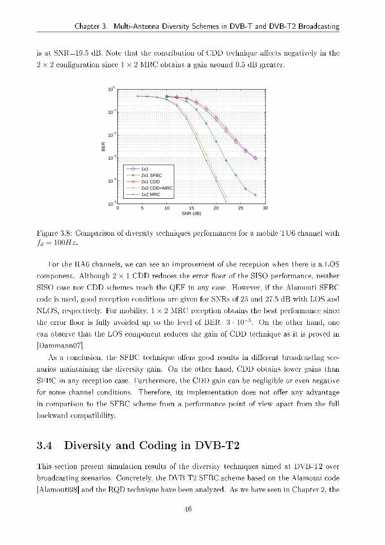
Chapter 3. Multi-Antenna Diversity Schemes in DVB-T and DVB-T2 Broadcasting
is at SNR=19.5 dB. Note that the contribution of CDD technique a�ects negatively in the
2× 2 con�guration since 1× 2 MRC obtains a gain around 0.5 dB greater.
0 5 10 15 20 25 3010
−5
10−4
10−3
10−2
10−1
100
SNR (dB)
BE
R
1x12x1 SFBC2x1 CDD2x2 CDD+MRC1x2 MRC
Figure 3.8: Comparison of diversity techniques performances for a mobile TU6 channel withfd = 100Hz.
For the RA6 channels, we can see an improvement of the reception when there is a LOS
component. Although 2 × 1 CDD reduces the error �oor of the SISO performance, neither
SISO case nor CDD schemes reach the QEF in any case. However, if the Alamouti SFBC
code is used, good reception conditions are given for SNRs of 25 and 27.5 dB with LOS and
NLOS, respectively. For mobility, 1× 2 MRC reception obtains the best performance since
the error �oor is fully avoided up to the level of BER=3 · 10−5. On the other hand, one
can observe that the LOS component reduces the gain of CDD technique as it is proved in
[Dammann07].
As a conclusion, the SFBC technique o�ers good results in di�erent broadcasting sce-
narios maintaining the diversity gain. On the other hand, CDD obtains lower gains than
SFBC in any reception case. Furthermore, the CDD gain can be negligible or even negative
for some channel conditions. Therefore, its implementation does not o�er any advantage
in comparison to the SFBC scheme from a performance point of view apart from the full
backward compatibility.
3.4 Diversity and Coding in DVB-T2
This section present simulation results of the diversity techniques aimed at DVB-T2 over
broadcasting scenarios. Concretely, the DVB-T2 SFBC scheme based on the Alamouti code
[Alamouti98] and the RQD technique have been analyzed. As we have seen in Chapter 2, the
46

Chapter 3. Multi-Antenna Diversity Schemes in DVB-T and DVB-T2 Broadcasting
5 10 15 20 25 3010
−5
10−4
10−3
10−2
10−1
100
SNR (dB)
BE
R
1x12x1 SFBC2x1 CDD2x2 CDD+MRC1x2 MRC
(a) RA6 LOS fd = 100 Hz
5 10 15 20 25 30 3510
−5
10−4
10−3
10−2
10−1
100
SNR (dB)
BE
R
1x12x1 CDD2x1 SFBC2x2 CDD+MRC1x2 MRC
(b) RA6 NLOS fd = 100 Hz
Figure 3.9: BER performances of multi-antenna schemes over 100 Hz mobile RA6 channelwith and without LOS.
former consist of a 2× 1 multi-antenna system which achieves the full channel capacity and
the latter is a frequency diversity technique which copes with deep fading scenarios. Both
techniques have been included as optional in the DVB-T2 speci�cations in order to increase
the robustness of the reception compared to its predecessor DVB-T.
We will analyze the performance of the DVB-T2 system with the mentioned techniques
and we will compare them to other schemes studied in DVB-T and the SISO case. Moreover,
we will brie�y describe the necessary soft detection in DVB-T2 since it is a key reception
issue which we will treat in detail in the ensuing chapters.
In the case of DVB-T2 system, the number of Monte Carlo realisations have been obtained
as follows:
target BER =100 erroneous bits
NMCNFECNIFLFECRc
, (3.14)
where NFEC corresponds to the number of FEC blocks per interleaving frame, NIF denotes
the number of interleaving frames and LFEC is the length of the LDPC block. In DVB-T2,
the QEF value after the LDPC decoder corresponds to BER=10−7 4. Reaching this value
involves a very long simulation time and a smaller value is often assumed in the literature
to keep simulation time reasonable. Since the performance of DVB-T2 is perfectly proved in
[DVB09], we have considered di�erent values of BER throughout this work depending on a
reference target. When it is assumed that QEF is actually reached, BER values of 10−3 or
10−4 have been used for evaluation considering a target BER of 10−6 for the Monte Carlo
realisations. Otherwise, the value of 10−7 is used considering the target BER of 10−8.
4A BER rate of 10−7 after LDPC decoder corresponds to approximately 10−11 after BCH decoder.
47

Chapter 3. Multi-Antenna Diversity Schemes in DVB-T and DVB-T2 Broadcasting
3.4.1 Soft Detection: The Maximum a Posteriori Detection
LDPC decoding requires soft estimates of the transmitted information bits. This is usually
carried out through the calculation of the a posteriori probabilities (APPs) of the received
symbols using the maximum a posteriori (MAP) detector. This method expresses this infor-
mation in the form of log-likelihood ratios (LLRs) (i.e. L-values [Hagenauer96]). The LLR
of a bit bk is de�ned as the logarithm of the ratio of the probabilities of the bit taking its
two possible values and can be expressed as
L(bk) = lnPr [bk = +1]
Pr [bk = −1], (3.15)
where the values of the bits are taken to be +1 and -1, representing logical `1' and `0', respec-
tively. From one constellation symbol, there are log2 P LLRs. Therefore, k = {0, . . . , log2 P}.We can assume that the information bits are scrambled by means of several interleavers in
such a way that the bits within the received symbol y may be considered statistically inde-
pendent. Therefore, using Bayes' rule in (3.15), the a posteriori information LD(bk|y) can
be expressed as follows:
LD(bk|y) = lnPr [bk = +1|y]
Pr [bk = −1|y]= LA(bk) + LE(bk|y), (3.16)
where LA(bk) and LE(bk|y) denote the a priori and extrinsic information, respectively. The
extrinsic information conditioned to the received symbol y can be written as
LE(bk|y) = ln
∑b∈Xk,+1
p(y|b) exp
(∑
j 6=k and bj=+1
LA(bj)
)
∑b∈Xk,−1
p(y|b) exp
(∑
j 6=k and bj=+1
LA(bj)
) , (3.17)
where s = map(b), s ∈ M is the mapping of the bit vector b into the symbol s of the
constellationM. The set X represents the set of all bit vectors with length log2 P , i.e. the
demapped set ofM. The expression Xk,+1 and Xk,−1 denote the subsets of X with the k-th
bit to +1 or −1, respectively.
Multiplying the numerator and denominator in (3.17) by exp(−∑log2 P−1
k=0 LA(bk)/2), we
obtain
LE(bk|y) = ln
∑b∈Xk,+1
p(y|b) exp(
12bT[k]LA,[k]
)
∑b∈Xk,−1
p(y|b) exp(
12bT[k]LA,[k]
) , (3.18)
where b[k] is the sub-vector of b obtained by omitting the k-th bit bk and LA,[k] denotes the
vector of all LA values, also omitting LA(bk). Now, we must calculate the likelihood function
48

Chapter 3. Multi-Antenna Diversity Schemes in DVB-T and DVB-T2 Broadcasting
p(y|b). Due to the Gaussian nature of the noise added at the receiver, the conditional
probability distribution function is given by
p(y|b) = p(y|s = map(b)) =exp− |y−hs|2
2σ2
2πσ2, (3.19)
where h is the �at fading channel which a�ects a speci�c OFDM carrier.
By replacing (3.19) in (3.18), we obtain the exact expression for the calculation of the
extrinsic information. However, the computation of the LLRs is usually simpli�ed for hard-
ware implementation by applying the Max-log approximation, which consists of a coarse
approximation of the Jacobian logarithm
ln (ea1 + ea2) = max(a1, a2) + ln(1 + e−|a2−a1|), (3.20)
by omitting the second term at the right-hand side of the equation. This correction term
can be considered negligible at the SNR range where a receiver usually operates, resulting
in a small performance degradation over the Jacobian logarithm approximation of (3.20)
[Robertson95]. This way, Equation (3.18) becomes
LE(bk|y) ≈1
2max
b∈Xk,+1
{− 1
σ2|y − hs|2 + bT[k]LA,[k]
}
−1
2max
b∈Xk,−1
{− 1
σ2|y − hs|2 + bT[k]LA,[k]
}. (3.21)
When iterative demapping is not used, there is no a priori information and (3.21) is
simpli�ed as
LE(bk|y) ≈1
2max
b∈Xk,+1
{− 1
σ2|y − hs|2
}
−1
2max
b∈Xk,−1
{− 1
σ2|y − hs|2
}. (3.22)
3.4.2 Rotated Constellations
The constellation rotation or RQD operation speci�ed in DVB-T2 aims to increase the
diversity order of the DVB-T2 BICM scheme. This technique is comprised of two stages:
correlating the I and Q components of the transmitted signal through the rotation of the
QAM constellation and making these components fade independently by means of a cyclic
49

Chapter 3. Multi-Antenna Diversity Schemes in DVB-T and DVB-T2 Broadcasting
delay of the Q component. The rotation of the constellation allows casting every constellation
symbol over I and Q axis independently in such a way that the whole information of the
QAM symbol can be taken from either the new I or Q components. The cyclic delay of the
Q component makes the I and Q components fade independently using a simpli�ed approach
of the signal space diversity (SSD) technique [Al-Semari97]. The insertion of a simple delay
for one of the two components avoids the loss of both I and Q signals due to the same fading
event, as it was shown in Figure 2.3.
One should note that whether RQD technique is used5, Equation (3.21) has to be slightly
modi�ed since the I (sI) and Q (sQ) components of the symbol s are subject to di�erent
fading channels, hI and hQ, respectively. Therefore, the extrinsic information is given as
LE(bk|y) ≈1
2max
b∈Xk,+1
{− 1
σ2|yI − hIsI |2 + |yQ − hQsQ|2 + bT[k]LA,[k]
}
−1
2max
b∈Xk,−1
{− 1
σ2|yI − hIsI |2 + |yQ − hQsQ|2 + bT[k]LA,[k]
}, (3.23)
where yI and yQ are the received I and Q values of y, respectively.
In order to analyze the performance of this technique, an approach for a �at Rayleigh
channel with erasures (RME) was proposed in [Nour08] and included later in [DVB09] for
DVB-T2. The proposed channel model substitutes the frame builder, the OFDM generation
blocks, the wireless channel and their corresponding inverse stages with an equivalent �at
fading channel as depicted in Figure 3.10. This way, the BICM module of the DVB-T2
standard is only necessary for the RQD assessment. The channel samples are considered
uncorrelated due to all the interleaving stages of DVB-T2. Hence, the equivalent received
symbol Y at discrete time t is given by
Y (t) = H(t)E(t)X(t) +N(t), (3.24)
where X(t) is the complex discrete transmit symbol, H(t) is a Rayleigh distributed fading
channel coe�cient with mean the unity, E(t) is a uniform random process which takes the
value of zero with probability PE and N(t) is the AWGN sample at time index t.
The work, which is presented below, was partially published in [Mendicute10]. Figure
3.11 presents the BER curves of the DVB-T2 BICM system as a function of CN over a RME
channel with 20% of erasures or lost carriers for two di�erent code rates, Rc = 3/4 and 2/3.
For the �rst case, the LDPC can not recover the lost information due to erasures and the
performance of the system without RQD tends to an error �oor above the QEF limit of
5The DVB-T2 speci�cation [DVB09] recommends its use at all times unless other incompatible techniqueis in use.
50

Chapter 3. Multi-Antenna Diversity Schemes in DVB-T and DVB-T2 Broadcasting
LDPC Encoder Bit Interleaver Demux bits to cells Mapper RQD Cell Interleaver Time Interleaver
BICM demodulator
Real/Imag to Complex
Normal RandomGenerator σ2 = 0.5
Uniform Random GeneratorInterval [0 1]
Normal RandomGenerator σ2 = 0.5
0 if u(t) ≤ PE1√
(1−PE)if u(t) > PE
H(t) E(t)
Random WGN Generatorσ2
N = 10−SNR/10
N(t)
Y(t)X(t)
BICM module
Figure 3.10: Equivalent DVB-T2 BICM system over �at fading Rayleigh channel with era-sures.
10−7. However, the diversity added by RQD makes LDPC correction possible providing a
considerable improvement. On the other hand, when the error-correcting capacity of the
code is greater, the improvement provided by RQD becomes smaller, as is shown in Figure
3.11 for the case of Rc = 2/3. Therefore, the gain of the system with RQD transmission
results very signi�cant over this kind of channels for high coding rates and low modulation
orders.
5 10 15 20 25 30 35 4010
−8
10−7
10−6
10−5
10−4
10−3
10−2
10−1
100
CN (dB)
BE
R
64−QAM Rc=3/4
64−QAM RQD Rc=3/4
QPSK Rc=3/4
QPSK RQD Rc=3/4
64−QAM RQD Rc=2/3
64−QAM Rc=2/3
QPSK Rc=2/3
QPSK RQD Rc=2/3
Figure 3.11: Performance of RQD in DVB-T2 BICM transmission with LFEC = 16200 overa �at Rayleigh channel with 20% of erasures.
If we now simulate the complete DVB-T2 system model of Figure 2.2 over a frequency-
selective TU6 channel, we can observe in Figure 3.12 that the gain of RQD decreases sig-
ni�cantly in comparison to the results displayed in the previous �gure. When the code rate
is high, the RQD technique improves the reception thanks to the increased diversity level.
Consequently, the RQD method can be taken into account for high code rates where the re-
51

Chapter 3. Multi-Antenna Diversity Schemes in DVB-T and DVB-T2 Broadcasting
dundancy rate of the coding is similar or even less than the loss of information. Furthermore,
when high-order modulation is used such as 64-QAM, the RQD gain is almost negligible.
However, if the modulation order is decreased, RQD o�ers an improvement of the reception.
As a result, one conclusion that can be drawn from the results depicted in Figures 3.11 and
3.12, is that the Rayleigh memoryless channel with erasures is not a very realistic channel
when modeling realistic hard transmission scenarios such as a TU6 channel.
4 6 8 10 12 14 16 18 2010
−6
10−5
10−4
10−3
10−2
10−1
SNR (dB)
BE
R
64−QAM R
c= 2/3
64−QAM Rc= 2/3 RQD
64−QAM Rc= 3/4
64−QAM Rc= 3/4 RQD
QPSK Rc= 2/3
QPSK Rc= 2/3 RQD
QPSK Rc= 3/4
QPSK Rc= 3/4 RQD
Figure 3.12: Performance of RQD in the SISO DVB-T2 system with LFEC = 64800 over aTU6 channel.
3.4.3 The DVB-T2 SFBC
This section presents simulation results of the DVB-T2 SFBC scheme over Rayleigh TU6 and
Ricean RA6 channels. The detection stage has been carried out using two methods. On one
hand, the decoupling of the transmitted signals based on the quasi-static fading assumption
[Alamouti98], where, by considering (2.19) for the 2× 1 con�guration, transmitted symbols
can be detected through
HHeq
[y1
y∗2
]=
[|h1|2 + |h2|2 0
0 |h1|2 + |h2|2
][s1
s2
], (3.25)
in such a way that s1 and s2 are completely decoupled. For the 2 × 2 case, the procedure
is the same using the equivalent channel in (2.21) instead. One should note that due to the
slight modi�cation in DVB-T2 of the original Alamouti STBC, Heq in (2.19) and (2.21) has
52
Chapter 3. Multi-Antenna Diversity Schemes in DVB-T and DVB-T2 Broadcasting
to be modi�ed following (2.28). On the other hand, if we assume that the channel can vary
in adjacent carriers, the linear ZF technique of (2.25) can be then considered. In this case,
the equivalent channel Heq distinguishes the channel coe�cients in adjacent carriers, such
that (2.28) is written for 2× 1 as
Heq =
[h1,c1 −h2,c1
h∗2,c2 h∗1,c1
], (3.26)
where the subscripts c1 and c2 denote the �rst and second carriers of each coded pair,
respectively. The considered DVB-T2 parameters are:
• Length of LDPC block: 64800 bits
• LDPC code rate: Rc = 2/3
• Constellation size: 64-QAM
• FFT size: 8192 carriers (8K)
• Guard interval: 1/4
Figure 3.13 shows the BER performance of the 2× 1 and 2× 2 SFBC schemes compared
to the SISO case over a TU6 channel. When the detection is based on ZF (denoted by adj=0
in the Figure), one can observe at the BER level of 10−4 that the 2 × 1 setup achieves a
performance gain around 2 dB whereas this is 6 dB for 2 × 2 con�guration. On the other
hand, we can see how the performance gains become smaller when quasi-static channel is
assumed (denoted by adj=1 in the Figure). If the channel is highly frequency selective such
as TU6, the use of an small FFT size (2K) involves that the channel of adjacent carriers
does not maintain invariant. As a result, the Alamouti detection based on the quasi-static
fading assumption leads to a slight loss of performance. When channels are time-variant,
the loss of performance could become greater.
In Figure 3.14 we show simulation results for a RA6 channel with LOS. In this case,
the performance gains compared to the SISO case are greater than the previous ones. At
a BER=10−4, they are around 3.5 and 8 dB for 2 × 1 and 2 × 2, respectively, when ZF
detection is used. One can note that the use of the detection based on the quasi-static
fading assumption has a negligible loss of performance in the RA6 channel. This is because
of RA6 is less frequency selective and the channel variation in adjacent carriers is much
lower.
3.5 Reception in SFN Networks
The main advantages of the SFN deployment strategy are the e�cient use of the television
spectrum, allowing a higher number of TV programs [Penttinen08], and the coverage in-
53

Chapter 3. Multi-Antenna Diversity Schemes in DVB-T and DVB-T2 Broadcasting
9 10 11 12 13 14 15 16 17
10−4
10−3
10−2
10−1
100
SNR (dB)
BE
R
1x18K adj=0 2x1 SFBC8K adj=1 2x1 SFBC8K adj=0 2x2 SFBC+MRC8K adj=1 2x2 SFBC+MRC2K adj=0 2x1 SFBC2K adj=1 2x1 SFBC2K adj=0 2x2 SFBC+MRC2K adj=1 2x2 SFBC+MRC
Figure 3.13: BER curves of diversity schemes in a DVB-T2 system with FFT sizes 2K and8K, 64-QAM modulation, code rate Rc = 2/3, LDPC block length LFEC = 64800 a�ectedby a TU6 channel.
9 10 11 12 13 14 15 16 17 18 1910
−5
10−4
10−3
10−2
10−1
100
SNR (dB)
BE
R
1x18K adj=0 2x1 SFBC8K adj=1 2x1 SFBC8K adj=0 2x2 SFBC+MRC8K adj=1 2x2 SFBC+MRC2K adj=0 2x1 SFBC2K adj=1 2x1 SFBC2K adj=0 2x2 SFBC+MRC2K adj=1 2x2 SFBC+MRC
Figure 3.14: BER curves of diversity schemes a�ected by a RA6 channel with LOS in aDVB-T2 system with FFT sizes 2K and 8K, 64-QAM modulation, LDPC block length of64800 bits and code rate Rc = 2/3
54

Chapter 3. Multi-Antenna Diversity Schemes in DVB-T and DVB-T2 Broadcasting
crease due to the SFN gain obtained through the positive contribution of the transmitters
[Santella04]. The latter advantage is not actually true since two identical delayed signals do
not only add constructively but also destructively leading to severe interference in speci�c
locations which can make the signal unrecoverable [Sobron09a]. This e�ect, which is called
self-interference, can be a nightmare for network planning and has been widely studied in
the literature [García-Lozano10, Morgade09, Mannino08]. This section analyzes the case of
self-interference for DVB-T2 SISO and the behavior of DVB-T2 system using a distributed
MISO network architecture.
3.5.1 Echoes in the SFN Network or Self-Interference
SFN networks are composed by several cells which are deployed to cover wide areas with an
unique frequency band. The border between cells, where receivers have sight from several
transmitters, is called overlapping area. The SFN network gain is de�ned as the positive
contribution due to constructive superposition of all received signals within the GI. However,
received signals can also add destructively despite being inside the GI. In order to observe
the negative e�ect in these areas, a simple constructive and destructive wave interference
problem is stated in [Sobron09a, Mendicute10] and explained below.
Two coherent sources generate wave forms ψ1(x, t) and ψ2(x, t) with speed v and direction
+x, so that:
ψ1(x, t) = <(A1ei(ω(t−xv )+ϕ1)) = <(A1e
i(ωt−kx+ϕ1)), (3.27)
ψ2(x, t) = <(A2ei(ω(t−xv )+ϕ2)) = <(A2e
i(ωt−kx+ϕ2)), (3.28)
where k = ωv
= 2πλis the angular wavenumber. The resulting waveform at a point P , whose
distances to the sources are d1 and d2, can be expressed as the real part of the sum of phasors
shown in Figure 3.15 as follows:
ψT (P, t) = AT cos(ωt+ ϕT ), (3.29)
where the resultant waveform amplitude is
AT =√A2
1 + A22 + 2A1A2 cos(k (d1 − d2) + ϕ1 − ϕ2). (3.30)
If τ0 is the resulting delay due to the distances and phase di�erences, Equation (3.30) can
be written as
AT =√A2
1 + A22 + 2A1A2 cos(2πfτ0), (3.31)
55

Chapter 3. Multi-Antenna Diversity Schemes in DVB-T and DVB-T2 Broadcasting
Figure 3.15: Phasor diagram of the waveforms.
where f is the carrier frequency. Equation (3.31) proves that the resultant waveform ampli-
tude will never be zero if received signals powers are di�erent. However, if power levels are
equal, involves that A1 = A2 = A and (3.31) can be expressed after some operations as
AT = 2A cos (πfτ0) . (3.32)
In this case, resultant waveform amplitude is periodically nulled. If we now consider
the wideband OFDM spectrum, AT will be zero when carrier frequency is equal to f =2n+12τ0
, n ∈ Z+. The number of zeros within the OFDM spectrum depends on the delay
between transmitters since the distance between nulls is ∆f = 1/τ0. Considering a DVB-
T or DVB-T2 system with 8K FFT size and GI length 1/4, an echo delayed half a guard
interval involves τ0=112 µs. Therefore, there is a null every 9 KHz within 8 MHz OFDM
spectrum as shows Figure 3.16(b). If the distance between carriers is 1.1 KHz, one out of
nine carriers is nulled, losing its information. One should note that the previous analysis
does not take into account channel considerations such as fading coe�cients or noise power.
However, it is enough to prove the carrier destruction in the SFN reception.
Simulation results for an AWGN channel a�ected by an echo are depicted in Figure 3.17
using a DVB-T2 system with parameters:
• RQD constellation
• Length of LDPC block: 16200 bits
• LDPC code rate: Rc = 3/5
• Constellation size: 64-QAM
56
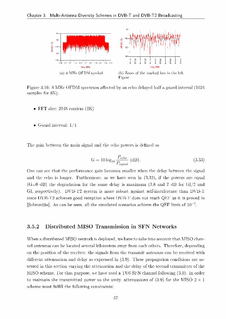
Chapter 3. Multi-Antenna Diversity Schemes in DVB-T and DVB-T2 Broadcasting
(a) 8 MHz OFDM symbol (b) Zoom of the marked box in the leftFigure
Figure 3.16: 8 MHz OFDM spectrum a�ected by an echo delayed half a guard interval (1024samples for 8K).
• FFT size: 2048 carriers (2K)
• Guard interval: 1/4
The gain between the main signal and the echo powers is de�ned as
G = 10 log10
PechoPsignal
(dB). (3.33)
One can see that the performance gain becomes smaller when the delay between the signal
and the echo is longer. Furthermore, as we have seen in (3.32), if the powers are equal
(G=0 dB) the degradation for the same delay is maximum (3.8 and 7 dB for GI/2 and
GI, respectively). DVB-T2 system is more robust against self-interference than DVB-T
since DVB-T2 achieves good reception where DVB-T does not reach QEF as it is proved in
[Sobron09a]. As can be seen, all the simulated scenarios achieve the QEF limit of 10−7.
3.5.2 Distributed MISO Transmission in SFN Networks
When a distributed MISO network is deployed, we have to take into account that MISO chan-
nel antennas can be located several kilometers away from each others. Therefore, depending
on the position of the receiver, the signals from the transmit antennas can be received with
di�erent attenuation and delay as expressed in (3.9). These propagation conditions are as-
sessed in this section varying the attenuation and the delay of the second transmitter of the
MISO scheme. For that purpose, we have used a TU6 SFN channel following (3.9). In order
to maintain the transmitted power to the unity, attenuations of (3.9) for the MISO 2 × 1
scheme must ful�ll the following constraints:
57

Chapter 3. Multi-Antenna Diversity Schemes in DVB-T and DVB-T2 Broadcasting
10 11 12 13 14 15 16 17 18 19 20 2110
−8
10−7
10−6
10−5
10−4
10−3
10−2
10−1
100
SNR (dB)
BE
R
G= 0 dB Del.= GIG= 0 dB Del.= GI/2G= −1 dB Del.= GIG= −1 dB Del.= GI/2G= −3 dB Del.= GIG= −3 dB Del.=GI/2Without echo
Figure 3.17: BER performance for DVB-T2 system a�ected by echoes of di�erent powerdelayed GI and GI/2 in an AWGN channel.
2∑
k=1
α2k = 1, (3.34)
G = 10 log10
α22
α21
. (3.35)
With these considerations, simulation results are provided in Figure 3.18 for the DVB-T2
systems with the following parameters:
• Length of LDPC block: 64800 bits
• LDPC code rate: Rc = 2/3
• Constellation size: 64-QAM
• FFT size: 8192 carriers (8K)
• Guard interval: 1/4
Considering the delay of the �rst transmitter equal to zero, i.e. t1 = 0, the values of the
G and t2 are shown in Table 3.4. One can observe in Figure 3.18 that delays longer than 0.75
GI do not allow a correct reception of the signal, since the BER performance has an error
�oor over the QEF. On the other hand, we can see that similar attenuations, i.e. α1 ≈ α2,
58
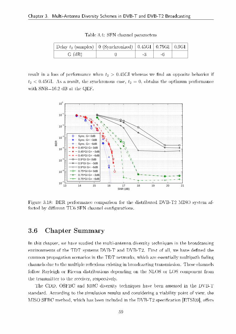
Chapter 3. Multi-Antenna Diversity Schemes in DVB-T and DVB-T2 Broadcasting
Table 3.4: SFN channel parameters
Delay t2 (samples) 0 (Synchronized) 0.45GI 0.75GI 0.9GI
G (dB) 0 -3 -6
result in a loss of performance when t2 > 0.45GI whereas we �nd an opposite behavior if
t2 < 0.45GI. As a result, the synchronous case, t2 = 0, obtains the optimum performance
with SNR=16.2 dB at the QEF.
13 14 15 16 17 18 19 20 2110
−7
10−6
10−5
10−4
10−3
10−2
10−1
100
SNR (dB)
BE
R
Sync. G= 0dBSync. G= −3dBSync. G= −6dB0.45*GI G= 0dB0.45*GI G= −3dB0.45*GI G= −6dB0.9*GI G= 0dB0.9*GI G= −3dB0.9*GI G= −6dB0.75*GI G= 0dB0.75*GI G= −3dB0.75*GI G= −6dB
Figure 3.18: BER performance comparison for the distributed DVB-T2 MISO system af-fected by di�erent TU6 SFN channel con�gurations.
3.6 Chapter Summary
In this chapter, we have studied the multi-antenna diversity techniques in the broadcasting
environments of the TDT systems DVB-T and DVB-T2. First of all, we have de�ned the
common propagation scenarios in the TDT networks, which are essentially multipath fading
channels due to the multiple re�exions existing in broadcasting transmission. These channels
follow Rayleigh or Ricean distributions depending on the NLOS or LOS component from
the transmitter to the receiver, respectively.
The CDD, OSFBC and MRC diversity techniques have been assessed in the DVB-T
standard. According to the simulation results and considering a viability point of view, the
MISO SFBC method, which has been included in the DVB-T2 speci�cation [ETSI09], o�ers
59

Chapter 3. Multi-Antenna Diversity Schemes in DVB-T and DVB-T2 Broadcasting
the best trade-o� between performance and deployment cost. The 2 × 1 OSFBC achieves
the same diversity gain as the 1× 2 MRC. Therefore, by using transmit diversity instead of
receive diversity, the cost of receivers can be reduced maintaining the diversity performance.
On the other hand, although the inclusion of CDD does not need any modi�cations in
the reception stage, its performance is negligible or even negative in scenarios such as very
frequency selective channels or Ricean channels, respectively.
For the DVB-T2 system, an analysis of the standard options have been carried out from a
diversity point of view. Due to the utilization of an LDPC coding, the necessary soft-output
MAP detection has been previously described.
The last part of the chapter has focused on two situations which can be given in SFN
networks. First, the echoes inside the SFN network due to other interfering transmitters
have been analyzed. The contribution of various transmitters can a�ect negatively to the
received signal depending on the power di�erences and delays among transmitters. The
worst case is given when the power of di�erent transmitters is similar at the receiver. In that
case, deep fadings along the OFDM symbol completely erase the information of the a�ected
carriers resulting in a considerable reduction of the BER performance.
The second issue has concerned with the distributed transmission of the DVB-T2 MISO
scheme. The MIMO concept is usually associated to various antennas located at the same
transmitter or receiver such that the power contribution of transmit antennas can be assumed
the same and the delay between signals negligible. However, the distributed DVB-T2 MISO
scheme consists of considering two transmitters of the SFN network as the transmit antennas
of the MISO channel. Therefore, due to the large distance between transmitters and receiver,
signal power and delays have to be taken into account in the channel modelling. Simulation
results showed that long delays between transmitted signals lead to a loss of performance
at the receiver. If the delay exceeds certain threshold value, the degradation could cause an
error �oor over the QEF limit. Therefore, the deployment of the SFN network results in a
key point for the optimum performance.
60

Chapter 4
Soft-Output MIMO Detection in
DVB-T2
4.1 Introduction
Multi-antenna diversity techniques o�er a higher robustness maintaining the bandwidth of
the system. As we have seen in the Chapter 3, the diversity gain is higher when the coding
gain is lower since bit error probability curves are further from the theoretical capacity
limit. In other words, when SFBC is used in DVB-T, we can observe a higher diversity gain
due to the lower error correction capability of a convolutional code. However, when MISO
is used in DVB-T2 which has a powerful FEC stage, the diversity gain becomes lower in
comparison to the DVB-T system due to the high coding gain the LDPC encoding o�ers.
So far, we have thought on MIMO techniques as a simple and e�cient way to obtain one
of their main advantages, diversity. However, MIMO channels can be exploited maximizing
the diversity-multiplexing frontier.
Currently, the main objective of the MIMO inclusion in future DTV systems is based on
combining diversity and spatial multiplexing, being various MIMO techniques analyzed for
that purpose. Nevertheless, FRFD codes are becoming an interesting proposal, being the
most remarkable the Golden code [Bel�ore04]. Due to the fact that FRFD codes include
spatial multiplexing, the computational cost of the detection at the receivers grows drasti-
cally. Therefore, it is important to �nd a trade-o� between their detection complexity and
performance.
This chapter studies the behavior of two FRFD codes with di�erent detection complexity
degrees over a DVB-T2 framework, since the DVB-T2 standard presents some key techniques
in the BICM stage which can be adopted by next-generation systems. First of all, we will
present the adaptation of the MAP detection for FRFD SFBC codes. In order to reduce the
calculation of the necessary soft information for the LDPC decoder, an LLR approximation
based on a list of candidates is seen, showing that the accuracy of the approximation depends
on the number of candidates. The performance of the list ML detector with the FRFD codes
61

Chapter 4. Soft-Output MIMO Detection in DVB-T2
is shown for di�erent broadcasting scenarios. Finally, the analysis of detection complexity
is drawn.
4.2 Soft Detection of SFBCs
In the same way as SISO schemes, the LDPC decoder requires a soft estimate of each
transmitted bit. However, unlike the symbol-wise detector for single-antenna transmission
(see Subsection 3.4.1), the computation of the LLRs of a given symbol of the SFBC code
will depend on the rest of coded symbols in the same codeword. Therefore, a soft-output
MAP detector has to be designed for MIMO detection.
4.2.1 SFBC MAP Detection
In order to detect the transmitted symbols of the vector s jointly, we rewrite the equations
of MAP detection considering the MIMO model in Chapter 2. Following (3.16), the a
posteriori information conditioned to the received vector LD(bk|Y ) will depend on the a
priori information LA(bk) and the channel observations given by extrinsic information. The
latter, which is conditioned to the received vector Y , can be expressed as
LE(bk|Y ) = ln
∑b∈Bk,+1
p(Y |b) exp
(∑
j∈Jk,bLA(bj)
)
∑b∈Bk,−1
p(Y |b) exp
(∑
j∈Jk,bLA(bj)
) , (4.1)
where p(Y |b) represents the likelihood function. De�ning Kb = MT log2 P as the number of
bits mapped into the symbol vector s, Bk,+1 represents the set of 2Kb−1 bit vectors b having
bk = +1 so that
Bk,+1 = {b|bk = +1} ,Bk,−1 = {b|bk = −1} , (4.2)
and Jk,b is the set of subindices that can be written as
Jk,b = {j|j = 0, . . . , Kb − 1, j 6= k, bj = +1} . (4.3)
4.2.2 Likelihood Function for SFBC MAP Detection
The most important part of the calculation of LE in (4.1) is the likelihood function p(Y |b).
Considering the system model in (2.2), we can rewrite H as an equivalent 4 × 4 MIMO
channel following (2.4). Thus, the equivalent channel can be expressed as
62

Chapter 4. Soft-Output MIMO Detection in DVB-T2
H =
[H1 0
0 H2
]=
h111 h1
12 0 0
h121 h1
22 0 0
0 0 h211 h2
12
0 0 h221 h2
22
, (4.4)
where hkij is the complex channel coe�cient from transmit antenna j to receive antenna i
at the k-th carrier. Note that we have distinguished between H1 and H2 since they are
equal if and only if the channel does not vary in adjacent carriers. By taking the elements
from matrices X and Y column-wise, we obtain the vectors x = [x11, x21, x12, x22]T and
y = [y11, y21, y12, y22]T , respectively. Now, considering the generator matrix G for the corre-
sponding SFBC, the system in (2.2) can be expressed as in (2.5) facilitating the calculation
of the likelihood function. Thus, p(Y |b) can be rewritten as
p(Y |s = map(b)) =
exp
(−‖y−HGs‖2
2σ2
)
(2πσ2)NT, (4.5)
where s = map(b) is the mapping of the vector b into the symbols of column vector s. In
the same way as the SISO case, only the term inside the exponent in (4.5) is relevant for the
calculation of LE, and the constant factor outside the exponent can be omitted. Therefore,
with the Max-log approximation, the extrinsic value LE in (4.1) becomes
LE(bk|Y ) ≈1
2max
b∈Bk,+1
{− 1
σ2
∥∥∥y − HGs∥∥∥
2
+ bT[k]LA,[k]
}
−1
2max
b∈Bk,−1
{− 1
σ2
∥∥∥y − HGs∥∥∥
2
+ bT[k]LA,[k]
}. (4.6)
The main di�culty in the calculation of (4.6) arises from the computation of the ML
metrics
∥∥∥y − HGs∥∥∥
2
, (4.7)
since a calculation of P 4 metrics is necessary for a 2× 2 FRFD SFBC. This becomes unfea-
sible for high modulation orders unless the calculation of (4.6) can be reduced. Therefore,
techniques that simplify and reduce the number of computed candidates are usually used.
63

Chapter 4. Soft-Output MIMO Detection in DVB-T2
4.2.3 List Detection
In order to reduce the calculation of LE in (4.6), a good approximation based on a candidate
list L of the ML metrics in (4.7) is proposed in [Hochwald03]. The list includes 1 ≤ Ncand <
P 4 vectors s with the smallest ML metrics in (4.7). The number of candidates Ncand must
be de�ned su�ciently large in such a way that it contains the maximizer of (4.6) with high
probability [Hochwald03]. Hence, (4.6) can be approximated as
LE(bk|Y ) ≈1
2max
b∈L∩Bk,+1
{− 1
σ2
∥∥∥y − HGs∥∥∥
2
+ bT[k]LA,[k]
}
−1
2max
b∈L∩Bk,−1
{− 1
σ2
∥∥∥y − HGs∥∥∥
2
+ bT[k]LA,[k]
}. (4.8)
One should note that either L ∩ Bk,+1 = ∅ or L ∩ Bk,−1 = ∅ make the computation
of the extrinsic information unfeasible. To solve this problem, a simple clipping of the LE
value is proposed in [Hochwald03]. Considering L su�ciently large, the fact that the k-th
bit for all symbol vectors of the candidate list L corresponds to +1 or −1 involves that the
corresponding LLR has a certain reliability. Therefore, truncating LE to a reliable value
should yield good results. There is not any established criteria in the literature, to the
best of our knowledge, to choose the suitable clipping value. Hence, several tests have been
carried out using di�erent statements. The di�erent options proposed are:
1. LE value truncated to ±8 [Hochwald03].
2. LE value truncated to ±80. In this case, we simply consider a high value of LE.
3. LE value truncated to ±d2min2σ2 . Noting that the sets Bk,+1 and Bk,−1 are delimited by
horizontal and vertical boundaries, two symbols in di�erent sets which are closest to
a received symbol always lie either on the same row (if the boundaries are vertical) or
on the same column (if the boundaries are horizontal) [Surendra Raju04]. Therefore,
considering the least signi�cant bit (LSB), the most reliable LE corresponds to the
received symbol being equal to the constellation point, i.e. LE = ±d2min2σ2 , being dmin
the minimum distance between two adjacent points of the constellation.
4. The previous four statements give the same reliability to all bits whose extrinsic in-
formation is unable to calculate. Considering the obtained metrics for the candidate
list, we use the maximal metric in order to truncate the LE value in (4.8). Therefore,
64

Chapter 4. Soft-Output MIMO Detection in DVB-T2
Equation (4.8) is given by
LE(bk|Y ) ≈1
2min
b∈L∩Bk,−1
{− 1
σ2
∥∥∥y − HGs∥∥∥
2
+ bT[k]LA,[k]
}
−1
2max
b∈L∩Bk,−1
{− 1
σ2
∥∥∥y − HGs∥∥∥
2
+ bT[k]LA,[k]
}if L ∩ Bk,+1 = ∅ (4.9)
LE(bk|Y ) ≈1
2max
b∈L∩Bk,+1
{− 1
σ2
∥∥∥y − HGs∥∥∥
2
+ bT[k]LA,[k]
}
−1
2min
b∈L∩Bk,+1
{− 1
σ2
∥∥∥y − HGs∥∥∥
2
+ bT[k]LA,[k]
}if L ∩ Bk,−1 = ∅ (4.10)
Thus, when all metrics in the same set are similar, the reliability of LE is lower than
when the di�erence among metrics is higher.
Figure 4.1 shows the results with the di�erent proposals where one can observe that
options 1, 3 and 4 obtain similar BER performance being slightly better option 4. The
second case, where a high value has been chosen, shows a worse performance than the
others. Therefore, the 4th option has been chosen for the rest of simulations in the thesis.
11 11.5 12 12.5 13 13.5 14 14.5 1510
−5
10−4
10−3
10−2
10−1
SNR (dB)
BE
R
Option 4Option 1Option 3Option 2
Figure 4.1: BER performances for di�erent clipping options in a 2× 2 DVB-T2 system withGolden codes and 16-QAM modulation.
The list detection approach results in a good system performance and its complexity
depends on the method to obtain the candidate list L and on the number of candidates
Ncand.
65

Chapter 4. Soft-Output MIMO Detection in DVB-T2
0 20 40 60 80 10010
−4
10−3
10−2
Number of candidates Ncand
BE
R
Gold List ML 14 dBSS List ML 14 dBGold List ML 14.4 dB
Figure 4.2: BER performances modifying the number of candidates Ncand for di�erent SNRvalues in a 2× 2 DVB-T2 system with Golden and SS codes using 16-QAM modulation.
4.2.4 Choice of Candidates Number
As we have previously mentioned, the number of candidates has to be su�ciently large
to contain the maximizer of (4.6) with high likelihood since the ML estimate sml is not
necessarily the estimate that maximizes (4.6). In order to �nd the magnitude of Ncand from
which the approximation (4.6) can be considered reliable, a battery of simulation have been
carried out modifying the Ncand used to compute (4.8). All the simulations have focused
on a 2 × 2 FRFD SFBC system with modulation order P = 16 over a TU6 channel. For
this con�guration, the exhaustive search corresponds to computing P 4 = 65536 metrics. In
Figure 4.2, we observe that the BER performance converges forNcand > 30 for di�erent SNRs.
This involves that a candidate list larger than Ncand = 50 does not o�er any performance
increase and consequently, candidate search can be reduced optimizing the computational
cost of the search algorithm.
4.3 Performance Results of FRFD Schemes in DVB-T2
Broadcasting Scenarios
This section presents simulation results, based on BER curves, for FRFD SFBC codes in a
DVB-T2 framework for di�erent reception conditions, which have published in [Sobron10a].
Unlike the DVB-T2 MISO scheme where a symbol-wise soft detection is possible, the de-
coding of FRFD codes requires the proposed list version of the MAP detection algorithm in
order to obtain the necessary soft information for the LDPC decoder. This involves a higher
operation number, which increases the detection complexity. This study basically compares
the performances of the Golden and the Sezginer-Sari (SS) codes, which have di�erent detec-
66
Chapter 4. Soft-Output MIMO Detection in DVB-T2
tion complexities, to the DVB-T2 MISO technique combined with an MRC at the receiver.
Hence, all the systems have the same diversity order. However, the FRFD codes' spatial
rate is twice as the DVB-T2 MISO scheme for the same modulation order. As a result,
FRFD codes allow to transmit the same data rate with lower-order modulations. In order
to perform a fair comparison among the SFBC codes, we de�ne the spatial rate S as
S =Q
T. (4.11)
Hence, the raw bit rate η of the system is given by η = SRc log2 P . Note that the raw
bit rate is de�ned as the data bit rate before LDPC coding. On the other hand, the BER
curves are presented as a function of the SNR per raw bit. As the fading channel coe�cients
are independent with unit variance, the signal energy per receive antenna is also the unity.
Therefore, the N receive antennas collect an overall average energy of N , bearing RcS log2 P
raw bits. Thus, considering the relation between the CN ρ and the SNR of (3.11), the SNR
per raw bit EbN0
can be expressed as
EbN0
=NFFTNρ
NCRcS log2 P. (4.12)
The simulator is based on a 2× 2 setup over the DVB-T2 system. Figure 4.3 depicts an
schematic diagram of the system without including other di�erent interleaving stages which
have been also added (frequency, cell and time interleavers). The performance has been
assessed using the same raw bit rate η and the same bit energy Eb for all SFBC schemes.
The DVB-T2 parameters are the following:
• Length of LDPC block: LFEC = 64800 bits
• LDPC code rate: Rc = 2/3
• Constellation sizes: QPSK, 16-QAM and 256-QAM
• FFT size: 2048 carriers (2K)
• Guard interval: 1/4
The simulations have been carried out over the Rayleigh channel TU6 and the Ricean channel
RA6. We consider perfect channel state information (CSI) at the receiver and non-iterative
MIMO detection. Therefore, there is no a priori information LA(bk) and hence (4.8) is
simpli�ed. The BER performance has been yielded for the number of candidates Ncand = 100
using the ML algorithm and keeping the 100 symbol vectors s which provide the lowest
metrics in order to compute (4.8). This method is not e�cient at all since there exist low-
complexity detection algorithms for that purpose, as we will see in the following chapter.
Furthermore, according to Figure 4.2, we can observe that the BER performance converges
67
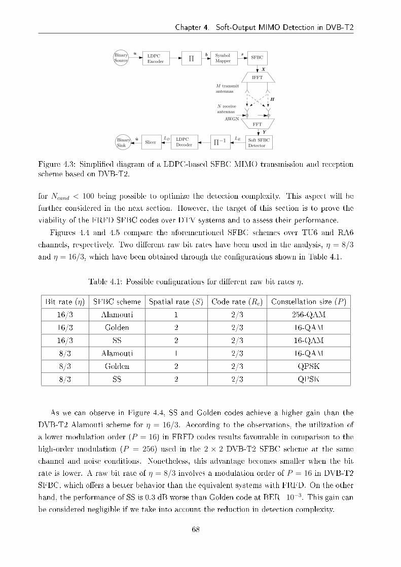
Chapter 4. Soft-Output MIMO Detection in DVB-T2
BinarySource
BinarySink
Π
Π−1
IFFT
FFT
SymbolMapper
SFBC
AWGN
Soft SFBCDetector
M transmitantennas
LESlicer
LD
LDPCEncoder
LDPCDecoder
N receiveantennas
u b s
X
H
Y
u
Figure 4.3: Simpli�ed diagram of a LDPC-based SFBC MIMO transmission and receptionscheme based on DVB-T2.
for Ncand < 100 being possible to optimize the detection complexity. This aspect will be
further considered in the next section. However, the target of this section is to prove the
viability of the FRFD SFBC codes over DTV systems and to assess their performance.
Figures 4.4 and 4.5 compare the aforementioned SFBC schemes over TU6 and RA6
channels, respectively. Two di�erent raw bit rates have been used in the analysis, η = 8/3
and η = 16/3, which have been obtained through the con�gurations shown in Table 4.1.
Table 4.1: Possible con�gurations for di�erent raw bit rates η.
Bit rate (η) SFBC scheme Spatial rate (S) Code rate (Rc) Constellation size (P )
16/3 Alamouti 1 2/3 256-QAM
16/3 Golden 2 2/3 16-QAM
16/3 SS 2 2/3 16-QAM
8/3 Alamouti 1 2/3 16-QAM
8/3 Golden 2 2/3 QPSK
8/3 SS 2 2/3 QPSK
As we can observe in Figure 4.4, SS and Golden codes achieve a higher gain than the
DVB-T2 Alamouti scheme for η = 16/3. According to the observations, the utilization of
a lower modulation order (P = 16) in FRFD codes results favourable in comparison to the
high-order modulation (P = 256) used in the 2 × 2 DVB-T2 SFBC scheme at the same
channel and noise conditions. Nonetheless, this advantage becomes smaller when the bit
rate is lower. A raw bit rate of η = 8/3 involves a modulation order of P = 16 in DVB-T2
SFBC, which o�ers a better behavior than the equivalent systems with FRFD. On the other
hand, the performance of SS is 0.3 dB worse than Golden code at BER=10−3. This gain can
be considered negligible if we take into account the reduction in detection complexity.
68
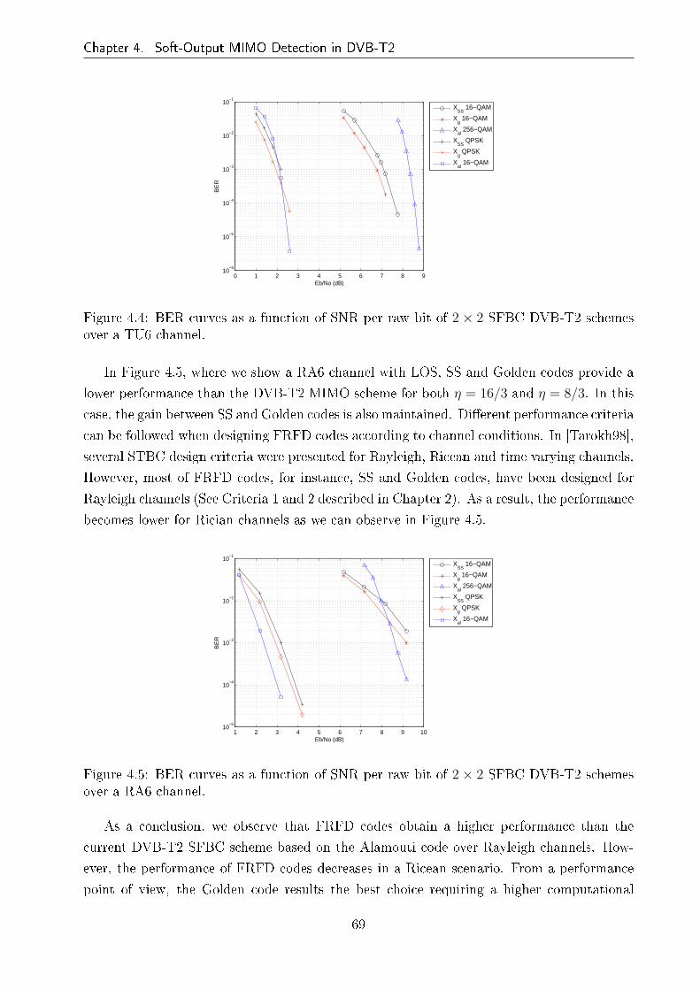
Chapter 4. Soft-Output MIMO Detection in DVB-T2
0 1 2 3 4 5 6 7 8 910
−6
10−5
10−4
10−3
10−2
10−1
Eb/No (dB)
BE
R
X
SS 16−QAM
Xg 16−QAM
Xal
256−QAM
XSS
QPSK
Xg QPSK
Xal
16−QAM
Figure 4.4: BER curves as a function of SNR per raw bit of 2 × 2 SFBC DVB-T2 schemesover a TU6 channel.
In Figure 4.5, where we show a RA6 channel with LOS, SS and Golden codes provide a
lower performance than the DVB-T2 MIMO scheme for both η = 16/3 and η = 8/3. In this
case, the gain between SS and Golden codes is also maintained. Di�erent performance criteria
can be followed when designing FRFD codes according to channel conditions. In [Tarokh98],
several STBC design criteria were presented for Rayleigh, Ricean and time varying channels.
However, most of FRFD codes, for instance, SS and Golden codes, have been designed for
Rayleigh channels (See Criteria 1 and 2 described in Chapter 2). As a result, the performance
becomes lower for Rician channels as we can observe in Figure 4.5.
1 2 3 4 5 6 7 8 9 1010
−5
10−4
10−3
10−2
10−1
Eb/No (dB)
BE
R
X
SS 16−QAM
Xg 16−QAM
Xal
256−QAM
XSS
QPSK
Xg QPSK
Xal
16−QAM
Figure 4.5: BER curves as a function of SNR per raw bit of 2 × 2 SFBC DVB-T2 schemesover a RA6 channel.
As a conclusion, we observe that FRFD codes obtain a higher performance than the
current DVB-T2 SFBC scheme based on the Alamouti code over Rayleigh channels. How-
ever, the performance of FRFD codes decreases in a Ricean scenario. From a performance
point of view, the Golden code results the best choice requiring a higher computational
69

Chapter 4. Soft-Output MIMO Detection in DVB-T2
cost. Nonetheless, SS codes reduce the detection complexity at the expense of sacri�cing
performance. Moreover, FRFD codes would allow to increase the data rate using higher
modulation orders such as 64-QAM. For that purpose, it would be necessary the utilization
of low-complexity soft detection algorithms as the ones proposed in the following sections.
4.4 Complexity of List Sphere Decoder-Based Soft
Detectors
The main disadvantage of the implementation of 2 × 2 FRFD codes in DTV systems is
the high computational cost of the detection stage. When computing (4.6), the calculation
of P 4 Euclidean distances would be necessary, which would result unfeasible for a realistic
implementation. For the complexity reduction, we can approximate (4.6) to (4.8) with a
list of candidates instead of computing all Euclidean distances. Di�erent algorithms can
be used when considering the candidate list. The list sphere decoder (LSD) algorithm
[Hochwald03] is considered in the literature as the most promising approach to provide soft
information. However, we review some low-complexity soft-detection algorithms analyzing
their advantages and disadvantages for the DTV system under consideration.
4.4.1 List Sphere Decoder
The LSD was proposed in [Hochwald03] as a means of obtaining soft information in MIMO
detection. Basically, the functionality of SD is extended to generate a list of candidates which
maximizes (4.8) such that the extrinsic information LE is approximated without having to
consider the entire set of possible transmitted symbol vectors. Instead, the information about
the demapped bits from the list of candidate vectors is only considered. The complexity of
the algorithm and the accuracy of the soft information will depend on the size of the list.
Hence, a good trade-o� must be found. If a large number of candidates is considered, the
approximated L-value will be closer to the exact solution but the LSD will require a larger
number of operations to generate the complete list.
The LSD proposed in [Hochwald03] is based on the FP enumeration. Consequently, the
choice of the initial radius R is extremely important to limit the complexity. Furthermore,
its calculation may result in a non-deterministic polynomial-time hard (NP-hard) problem
if we use the covering radius of the lattice [Conway88] for that purpose. Apart from the
disadvantages of the FP enumeration, the LSD presents the same problems of the SD from
an implementation point of view: its variable complexity depending on the noise level and
the channel conditions and its sequential nature. Di�erent modi�cations have been proposed
for the original LSD, although most of them still use the FP enumeration. In [Boutros03], a
modi�cation of the LSD has been proposed combining the original SD with SE enumeration
70

Chapter 4. Soft-Output MIMO Detection in DVB-T2
and a double FP enumeration. The SE-SD is used to obtain the ML solution and then the
double FP enumeration generates a list of candidates around the ML solution instead of the
received vector. Although the performance of the LSD is improved, this solution has di�erent
problems such as the complexity increment, the irregular structure of the algorithm and the
possible re-enumeration of the same vectors in the SE-SD and the double FP enumeration.
Other solutions based on the addition of the a priori information [Vikalo04, Park05, Sumii05]
have been proposed to improve the soft value computation and to reduce the complexity.
However, they have been proposed from a theoretical point of view and their additional
number of operations would represent a problem for a realistic implementation.
With the utilization of the SE enumeration in [Lee06], a feasible LSD was proposed from
an implementation point of view. It consists of taking a very large initial radius following
the SE enumeration so that it is maintained until the list of candidates is full. Then, the
initial radius is set to the largest distance among the candidates on the list and the operation
continues replacing the candidate with the largest distance on the list if new candidates are
found satisfying the new sphere constraint.
4.4.1.1 Complexity Results
Simulation results are here presented to analyze the complexity reduction of the SE-LSD
compared to the computation of P 4 Euclidean distances in a previously used list ML. In
addition, we will observe the behavior of the SE-LSD as a function of either the noise
level or the size of the list. The simulations have been carried out for the Golden code
scheme with 16-QAM modulation in the DVB-T2 framework and over a TU6 channel. If
the complex-valued version of the LSD is considered, the number of nodes per tree level is
ntree = [P 4 P 3 P 2 P ] considering the level i = 1 at the bottom of the tree. Note that the
number of levels corresponds to the Q = 4 symbols coded in any 2× 2 FRFD code and the
number of nodes in the level i = 1 is the overall Euclidean distances.
Figure 4.6 shows the average number of visited nodes per tree level as a function of the
SNR for a LSD decoder with Ncand = 50 candidates. One can observe that the behavior
of the LSD does not notably vary in that range of noise power. Unlike the SD, where
the highest average number of visited nodes arises at the intermediate levels due to the
pruning generated by the reduction of the hypersphere radius, the LSD has the greatest
average number of visited nodes at the last level, due to the necessary updating of the list
of candidates.
If we analyze the complexity of the tree search as a function of the number of list candi-
dates, Table 4.2 shows us that the average number of visited nodes per tree level becomes
greater when Ncand increases, being the higher di�erence at level i = 1. The last level re-
quires a larger number of operations than the rest of levels. Therefore, an increment of
visited nodes in that level involves a much higher computational cost. As a result, consider-
71

Chapter 4. Soft-Output MIMO Detection in DVB-T2
12.5 13 13.5 14 14.5 150
50
100
150
200
250
SNR (dB)
Ave
rage
num
ber
of v
isite
d no
des
per
leve
l
i=1i=2i=3i=4
Figure 4.6: Average number of visited nodes per tree level as a function of SNR for SE-LSDdetection of Golden codes with 16-QAM modulation and Ncand = 50.
ing the simulation results of Figure 4.2 for a TU6 channel, the choice of Ncand = 50 o�ers a
trade-o� between accuracy and complexity. Note that we have measured the average number
of visited nodes at the highest SNR value (14.8 dB) of Figure 4.6 so that the average values
correspond to the most optimistic situation for the studied range of SNR.
Table 4.2: Average number of visited nodes for LSD detection of Golden codes with 16-QAMmodulation using di�erent number of candidates at SNR=14.8 dB.
hhhhhhhhhhhhhhhhhhhhhhhTree level
Number of candidates (Ncand)25 50 100
i = 1 97.27 201.80 409.73
i = 2 77.26 118.67 183.71
i = 3 42.38 54.35 69.23
i = 4 7.78 8.76 9.81
As we have mentioned before, one of the two main drawbacks of the LSD algorithm
is the variable nature according to the channel and noise conditions. This feature can be
depicted in Figures 4.7 and 4.8 for Ncand = 50 and 100, respectively, where the histograms of
the number of visited node are shown. The overall number of channel realisations has been
502260, while the number of realizations per number of visited nodes has been normalized
to the unity and expressed as percentage. Despite the average �gures shown in the Table
4.2, one can notice that the number of visited nodes for some channel realisations is higher
72

Chapter 4. Soft-Output MIMO Detection in DVB-T2
than the average values resulting in a problem for the detection process and verifying the
characteristic upper-bound equal to the ML detection complexity. For instance, in the level
i = 3 of Figures 4.7(c) and 4.8(c), we can observe that the 0.2 and 0.4 per cent of channel
realisations exceed 900 visited nodes even though the average values are 118.67 and 183.71
(dashed lines), respectively. This behavior can be seen at all levels reaching the entire number
of nodes at the levels i = 2 and 1.
4.4.2 Review of Fixed-Complexity Implementations
The variable computational cost of the LSD algorithm and its sequential nature negatively af-
fect the complexity of the architecture and the achievable throughput of the implementation.
In order to overcome that problem, although it is not strictly based on the LSD, the K-Best
[deJong05] and QRD-M [Dai05] algorithms were proposed as soft-MIMO detectors that have
a �xed complexity and can be fully pipelined in a hardware implementation. However, the
algorithms su�er from high computational complexities depending on the parameter M. The
K-Best lattice decoder has been implemented in practice to obtain soft-information proving
its �xed complexity and its fully-pipelined architecture [Guo06]. However, the implementa-
tion shows that the sorting procedure required in each level represents a signi�cant percentage
of the overall complexity. Other algorithms exist with comparable performance to that of
the LSD. In [Radosavljevic09], bounded soft sphere detection (BSSD) with probabilistically
determined and variable search bounds per search level is proposed, being also suitable for
the pipelining of search levels. In [Barbero08], an extension of the �xed-complexity sphere
decoder (FSD) [Barbero06b] for turbo-MIMO detection called list �xed-complexity sphere
decoder (LFSD) was proposed with interesting results. In accordance to [Jaldén07], the FSD
maintains the diversity of the ML while searching over only a very small number of candi-
dates. Therefore, given the lower complexity of the LFSD and its quasi-ML performance,
we will show in next chapter that the same concept can be applied to the FRFD detection
with a redesign of the ordering procedure, resulting in a more optimized implementation of
the algorithm.
4.5 Chapter Summary
In the development groups of forthcoming DTV standards such as DVB-NGH, the inclusion
of MIMO technologies based on FRFD codes have been proposed. This chapter has presented
a performance analysis of FRFD codes in last-generation DTV systems, such as DVB-T2,
and has discussed the complexity issues related to soft detection.
First of all, soft detection has been described rewriting the equations of the MAP detector
for FRFD SFBC codes. Furthermore, a MAP algorithm approximation based on a list
73
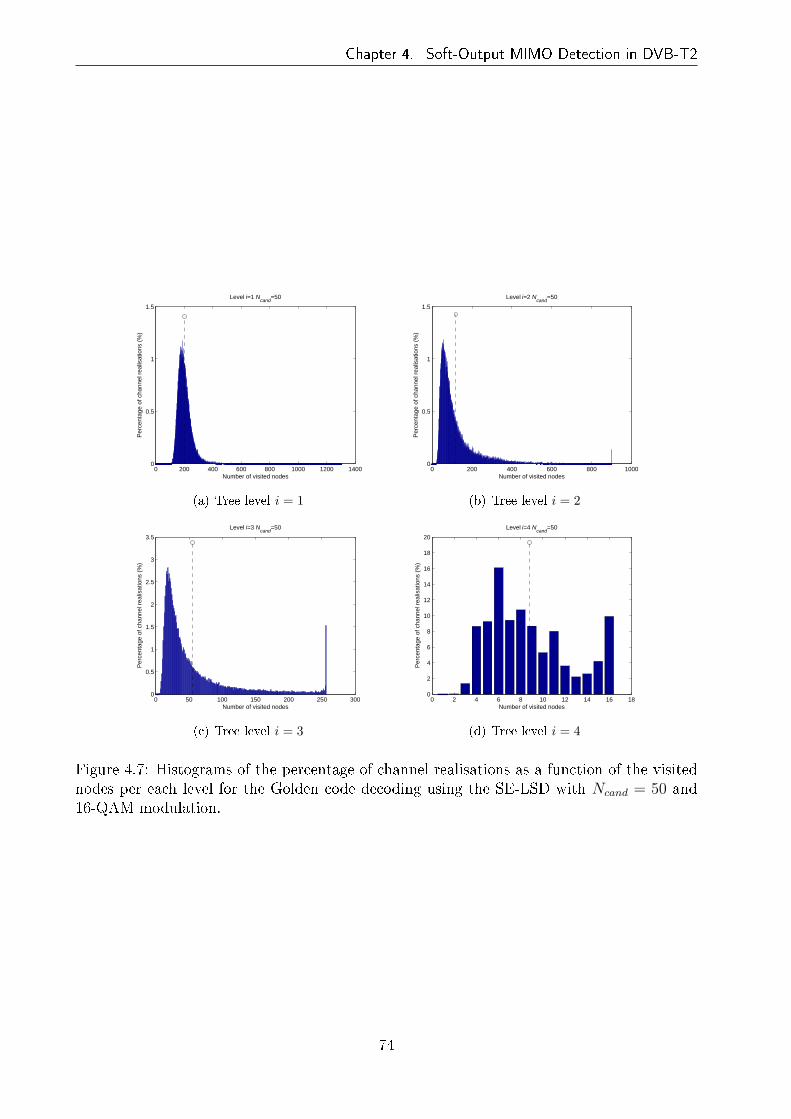
Chapter 4. Soft-Output MIMO Detection in DVB-T2
0 200 400 600 800 1000 1200 14000
0.5
1
1.5
Per
cent
age
of c
hann
el r
ealis
atio
ns (
%)
Number of visited nodes
Level i=1 Ncand
=50
(a) Tree level i = 1
0 200 400 600 800 10000
0.5
1
1.5
Per
cent
age
of c
hann
el r
ealis
atio
ns (
%)
Number of visited nodes
Level i=2 Ncand
=50
(b) Tree level i = 2
0 50 100 150 200 250 3000
0.5
1
1.5
2
2.5
3
3.5
Per
cent
age
of c
hann
el r
ealis
atio
ns (
%)
Number of visited nodes
Level i=3 Ncand
=50
(c) Tree level i = 3
0 2 4 6 8 10 12 14 16 180
2
4
6
8
10
12
14
16
18
20
Per
cent
age
of c
hann
el r
ealis
atio
ns (
%)
Number of visited nodes
Level i=4 Ncand
=50
(d) Tree level i = 4
Figure 4.7: Histograms of the percentage of channel realisations as a function of the visitednodes per each level for the Golden code decoding using the SE-LSD with Ncand = 50 and16-QAM modulation.
74

Chapter 4. Soft-Output MIMO Detection in DVB-T2
0 200 400 600 800 1000 1200 14000
0.1
0.2
0.3
0.4
0.5
0.6
0.7
0.8
Per
cent
age
of c
hann
el r
ealis
atio
ns (
%)
Number of visited nodes
Level i=1 Ncand
=100
(a) Tree level i = 1
0 200 400 600 800 10000
0.1
0.2
0.3
0.4
0.5
0.6
0.7
0.8
0.9
1
Per
cent
age
of c
hann
el r
ealis
atio
ns (
%)
Number of visited nodes
Level i=2 Ncand
=100
(b) Tree level i = 2
0 50 100 150 200 250 3000
0.5
1
1.5
2
2.5
3
Per
cent
age
of c
hann
el r
ealis
atio
ns (
%)
Number of visited nodes
Level i=3 Ncand
=100
(c) Tree level i = 3
0 2 4 6 8 10 12 14 16 180
2
4
6
8
10
12
14
16
18
Per
cent
age
of c
hann
el r
ealis
atio
ns (
%)
Number of visited nodes
Level i=4 Ncand
=100
(d) Tree level i = 4
Figure 4.8: Histograms of the percentage of channel realisations as a function of the visitednodes per each level for the Golden code decoding using the SE-LSD with Ncand = 100 and16-QAM modulation.
75

Chapter 4. Soft-Output MIMO Detection in DVB-T2
of candidates is given. In order to �nd the trade-o� between complexity and accuracy,
simulations results have been presented for di�erent sizes of the list of candidates. Next,
performance simulation results have been shown for the Golden code and the low-complexity
SS code using di�erent data bit rates and broadcasting scenarios. The FRFD codes have
been compared to a 2× 2 DVB-T2 SFBC scheme with MRC detection at the receiver. The
drawback of multi-strata codes [Samuel07], such as the SS code, is their worse performance
in comparison to codes designed using number theory like the Golden code. However, due
to its multi-strata structure, they can be decoded with lower complexity sacri�cing the
performance.
In the last part of the chapter, detection complexity considerations have taken into ac-
count. Several low-complexity detection algorithms have been reviewed paying special at-
tention to the LSD algorithm. This method is considered as the most promising approach to
provide soft-information. However, as we have proved in the complexity results, its variable
complexity depending on the noise level and the channel conditions and its sequential nature
can a�ect its practical implementation. As a result, after reviewing some �xed-complexity
algorithms, a solution based on the LFSD of [Barbero08] for turbo-MIMO systems will be
proposed in the following chapter.
76

Chapter 5
List Fixed-Complexity Sphere Decoder
for FRFD Codes
5.1 Introduction
A redesign of the previously proposed LFSD for turbo-MIMO systems in [Barbero06a,
Barbero08] is developed in this chapter and adapted to SFBC-LDPC scenarios. Initially,
the LFSD algorithm was proposed to provide soft outputs in spatially multiplexed MIMO
systems. For that purpose, LFSD generates a subset or list of candidates from the entire
possible transmit constellation approaching the LSD performance with a �xed complexity
and resulting in a good option for hardware implementation. Before starting with the tree
search, the LFSD performs a channel ordering procedure which maximizes the algorithm
performance. In [Barbero06a], the ordering process is aimed at the spatially multiplexed
transmission where the subchannels which a�ect the transmitted symbols are uncorrelated
to each other. However, the equivalent subchannels of the FRFD SFBC coded symbols are
correlated through the code generator matrix G. Therefore, the channel ordering procedure
can follow a pattern which optimizes the performance of the LFSD algorithm. For that
purpose, the 2× 2 SFBC system is transformed to an equivalent 4× 4 MIMO system where
we take into account the mentioned correlation between subchannels.
A new version of the channel ordering stage is presented in this chapter for FRFD SFBC
coding. First, a theoretical revision of the previously proposed LFSD is performed and
the novel ordering algorithm is then introduced. The e�ect of the number of candidates
is analyzed in the DVB-T2 platform �nding a trade-o� between complexity reduction and
performance maximization. Simulation results are provided in order to show the performance
and complexity of the new algorithm compared to the original LFSD and the LSD. Finally,
further complexity considerations about number of operations are drawn.
77
Chapter 5. List Fixed-Complexity Sphere Decoder for FRFD Codes
5.2 The LFSD Algorithm
In order to limit the complexity and to facilitate the computation of the detected symbols, a
�xed-complexity tree-search-based algorithm was proposed in [Barbero06b] for spatial mul-
tiplexing schemes, named FSD. The FSD was developed with the purpose of overcoming
the two main drawbacks of the SD detection scheme in MIMO systems, �rst, the variable
complexity and second, the sequential nature of the algorithm. As in the case of the SD, the
distance calculations are performed following a tree-search fashion. The main feature of the
FSD is that, instead of constraining the search to those nodes whose accumulated Euclidean
distances are within a certain radius from the received signal, the search is performed in
an unconstrained fashion. The tree search is de�ned instead by a tree con�guration vector
n = [n1, . . . , nMT ], which determines the number of child nodes (ni) to be considered at
each level. Therefore, the tree is traversed level by level regardless of the sphere constraints.
Once the bottom of the tree is reached, the path leading to the smallest Euclidean distance
is selected as the FSD solution.
An extension to the FSD was proposed in [Barbero06a] for systems with soft symbol
information requirements. This soft-output algorithm, coined LFSD, performs an uncon-
strained tree search based on a certain tree con�guration vector n but, as opposed to the
FSD, retrieves a list of Ncand candidate symbol vectors. It is worth noting that the set G
composed of the Ncand selected symbol vectors may not correspond to the vectors of the Lset with the smallest metrics given by the LSD, but provides su�ciently small metrics and
diversity of bit values to obtain accurate soft information [Barbero08]. A representation of
an LFSD tree search is depicted in Figure 5.1 for a 2 × 2 FRFD SFBC with QPSK modu-
lation and a tree con�guration vector of n = [1, 1, 2, 4]. We can observe that at level i = 4,
all nodes are visited, whereas two nodes per branch are visited at the next levels, which
sum eight nodes in total. For the remainder levels, i = 2 and 1, the same overall number of
nodes, i.e. 8, is maintained since one child node is only chosen for each of the parent nodes
of the upper level.
For the sake of simplicity, the equations for the aforementioned FRFD codes will be
rearranged so that Euclidean distance can be given by
‖y −Heqs‖2 . (5.1)
where y and s are the received and transmitted signals reorganized according to the corre-
sponding code and Heq = HG is the e�ective equivalent channel as de�ned in (2.5). For
the previously studied codes, the corresponding complex-valued code generator matrices G
are the following:
78

Chapter 5. List Fixed-Complexity Sphere Decoder for FRFD Codes
n4=
n3=
n2=
n1=
Figure 5.1: Fixed-complexity tree search of a QPSK-modulated signal using a tree con�gu-ration vector of n = [1, 1, 2, 4]
GG =
1 + iθ 0 θ − i 0
0 −θ + i 0 1− iθ0 1 + iθ 0 θ − i
1 + iθ 0 θ − i 0
, GSS =
a 0 b 0
0 −c 0 −d0 a∗ 0 b∗
c∗ 0 d∗ 0
. (5.2)
A level-by-level computation of the metrics in (5.1) requires the conversion to the following
equivalent system ∥∥U(s− ˆs)∥∥2
2, (5.3)
where U is obtained through the Cholesky decomposition of HHeqHeq and ˆs = H†
eqy. Given
the triangular structure of U , it is now possible to compute the AED up to level i recursively
by traversing the tree backwards from level i = MT downto i = 1. The Euclidean distances
that must be minimized in the cost function in (2.40) can be equivalently represented in a
tree search fashion as
Di = u2ii |si − zi|2 +
MT∑
j=i+1
u2jj |sj − zj|2 = di +Di+1, (5.4)
and
zi = ˆsi −MT∑
j=i+1
uijuii
(sj − ˆsj), (5.5)
where Di and di are the AED and the partial (squared) Euclidean distance (PED) at level
i, respectively, and zi corresponds to the centre of the hypersphere.
Therefore, at each level i the ni symbols to be selected are chosen in accordance with the
SE enumeration [Schnorr91] and their corresponding PEDs di are computed and accumulated
to the previous level's AED, that is, Di+1. Once the bottom of the tree has been reached,
a sorting operation is performed on the nT =∏MT
i=1 ni Euclidean distances in order to select
79
Chapter 5. List Fixed-Complexity Sphere Decoder for FRFD Codes
the Ncand symbol vectors with the smallest metrics. This latter sorting procedure can be
avoided if the tree con�guration vector n is selected so as to yield nT = Ncand. In such a
case, the complexity of the algorithm is reduced but the quality of the soft information is
also degraded as the selected metrics are higher in value.
5.2.1 The Ordering Algorithm for FRFD SFBC
The performance of the LFSD soft-detector in uncoded scenarios is strongly dependent on
the ordering algorithm of the channel matrix and the choice of the tree con�guration vector
[Barbero06a]. However, in the speci�c case of FRFD SFBC systems the e�ect of the ordering
algorithm on the overall performance relies on the type of code utilized [Sobron10a]. For
a spatial multiplexed con�guration, the ordering algorithm proposed in [Barbero06a] to
enhance the performance of the LFSD and the FSD detectors was based on the fact that it
was possible to mitigate the error propagation derived from ruling out several tree branches
by ordering the several columns of the channel matrix depending on their quality. More
precisely, the FSD ordering dictates that the subchannel with the worst norm of all needs
to be processed �rst given that in that level all the constellation symbols are evaluated (see
Figure 5.1), and therefore, there is no error propagation to the other levels.
In the case of spatial multiplexing, each data symbol is transmitted from one transmit
antenna of the MIMO system such that their corresponding subchannels are completely
uncorrelated assuming that the distance between antennas is longer than half a wavelength.
Therefore, the columns of the channel matrix can be ordered independently. However, when
FRFD SFBCs are used, data symbols are usually transmitted in pairs (s1, s3) and (s2, s4)
through both spatial and frequency directions (see Chapter 2) such that the symbols of each
pair are a�ected by the same channel conditions. This feature as well as the power conditions
de�ned in (2.31), (2.32) and (2.33) make the ordering of the equivalent channel columns, i.e.
the subchannels of the coded symbols, to depend on the tree con�guration. Let us see this
assertions for SS and Golden codes in the sequel.
5.2.1.1 SS Code
When considering the equivalent system in (2.40) for the SS code, it is worthy noting that
the equivalent subchannels for the symbol pairs (s1, s3) and (s2, s4) have equal norms. This
is due to two main factors: on one hand, both symbol pairs undergo the same channel
conditions as they are assigned to adjacent carriers, and on the other hand, the code weights
a, b, c and d imposed by the SS code ful�ll the power constraint (2.33), which forces the
symbols to be dispersed with equal energy in all spatial and temporal directions. Let us
see it mathematically. If we represent the equivalent channel matrix Heq = HG in matrix
form, we obtain that
80
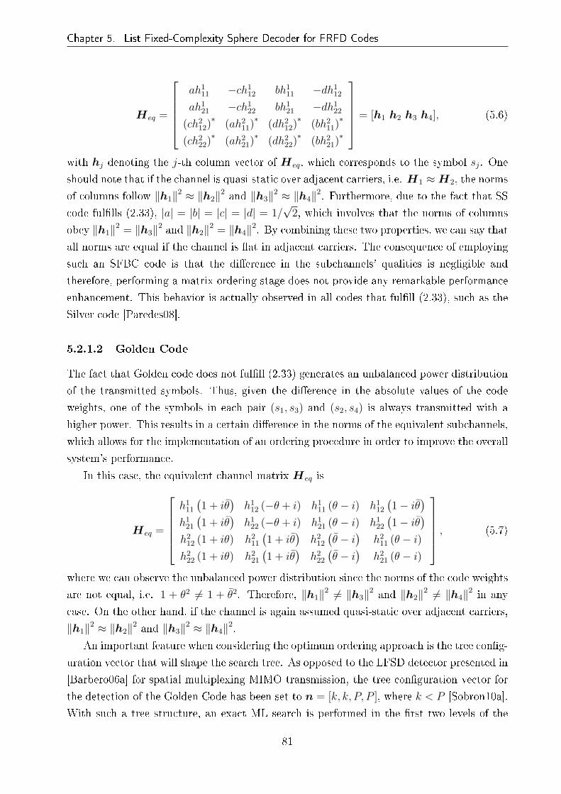
Chapter 5. List Fixed-Complexity Sphere Decoder for FRFD Codes
Heq =
ah111 −ch1
12 bh111 −dh1
12
ah121 −ch1
22 bh121 −dh1
22
(ch212)∗
(ah211)∗
(dh212)∗
(bh211)∗
(ch222)∗
(ah221)∗
(dh222)∗
(bh221)∗
= [h1 h2 h3 h4], (5.6)
with hj denoting the j-th column vector of Heq, which corresponds to the symbol sj. One
should note that if the channel is quasi-static over adjacent carriers, i.e. H1 ≈H2, the norms
of columns follow ‖h1‖2 ≈ ‖h2‖2 and ‖h3‖2 ≈ ‖h4‖2. Furthermore, due to the fact that SS
code ful�lls (2.33), |a| = |b| = |c| = |d| = 1/√
2, which involves that the norms of columns
obey ‖h1‖2 = ‖h3‖2 and ‖h2‖2 = ‖h4‖2. By combining these two properties, we can say that
all norms are equal if the channel is �at in adjacent carriers. The consequence of employing
such an SFBC code is that the di�erence in the subchannels' qualities is negligible and
therefore, performing a matrix ordering stage does not provide any remarkable performance
enhancement. This behavior is actually observed in all codes that ful�ll (2.33), such as the
Silver code [Paredes08].
5.2.1.2 Golden Code
The fact that Golden code does not ful�ll (2.33) generates an unbalanced power distribution
of the transmitted symbols. Thus, given the di�erence in the absolute values of the code
weights, one of the symbols in each pair (s1, s3) and (s2, s4) is always transmitted with a
higher power. This results in a certain di�erence in the norms of the equivalent subchannels,
which allows for the implementation of an ordering procedure in order to improve the overall
system's performance.
In this case, the equivalent channel matrix Heq is
Heq =
h111
(1 + iθ
)h1
12 (−θ + i) h111 (θ − i) h1
12
(1− iθ
)
h121
(1 + iθ
)h1
22 (−θ + i) h121 (θ − i) h1
22
(1− iθ
)
h212 (1 + iθ) h2
11
(1 + iθ
)h2
12
(θ − i
)h2
11 (θ − i)h2
22 (1 + iθ) h221
(1 + iθ
)h2
22
(θ − i
)h2
21 (θ − i)
, (5.7)
where we can observe the unbalanced power distribution since the norms of the code weights
are not equal, i.e. 1 + θ2 6= 1 + θ2. Therefore, ‖h1‖2 6= ‖h3‖2 and ‖h2‖2 6= ‖h4‖2 in any
case. On the other hand, if the channel is again assumed quasi-static over adjacent carriers,
‖h1‖2 ≈ ‖h2‖2 and ‖h3‖2 ≈ ‖h4‖2.
An important feature when considering the optimum ordering approach is the tree con�g-
uration vector that will shape the search tree. As opposed to the LFSD detector presented in
[Barbero06a] for spatial multiplexing MIMO transmission, the tree con�guration vector for
the detection of the Golden Code has been set to n = [k, k, P, P ], where k < P [Sobron10a].
With such a tree structure, an exact ML search is performed in the �rst two levels of the
81

Chapter 5. List Fixed-Complexity Sphere Decoder for FRFD Codes
tree, and therefore, there is no error propagation down to the next levels. Consequently, by
ordering the equivalent channel matrix in such a way that the worst subchannel is processed
in the �rst two levels of the tree, the probability of �nding vectors with smaller metrics is
increased. Moreover, it has to be taken into account that in the non-ML part of the tree
search the symbols belonging to the same symbol pair need to be detected together for a
better performance of the algorithm. The equivalent ordered channel matrix Hordeq to be
used in the detection of the Golden Code can then be described as
Hordeq = [hb hb hw hw], (5.8)
where
w = arg minj∈S‖hj‖2
2 , (5.9)
and
b = arg maxj∈S,j 6=w,w
‖hj‖22 , (5.10)
The two symbols that compose a symbol pair are represented as (a, a) and the set of symbol
indices is S = {1, · · · ,MT}. Given the chosen tree con�guration vector, one can notice that
the order of the �rst two selected symbols can be switched without having any impact on
the system's �nal performance.
As it will be shown in the next section, the proposed ordering approach yields close-to-
optimum performance when combined with the suggested tree con�guration vector. More-
over, the matrix ordering process only requires the computation of MT vector norms as op-
posed to other ordering algorithms such as FSD [Barbero06a] or V-BLAST [Wolniansky98],
which need to perform MT − 1 matrix inversion operations.
5.2.2 Bit LLR Generation for the Proposed List Fixed-Complexity
Detector
Once we have de�ned the equivalent system model for the FRFD codes, the expression for
the LLRs in (4.8) can be rewritten to comply with the equivalent system in (2.40) where the
list of candidates L of the ML/LSD detector has been substituted by the set G of the LFSD
so that
LE(bk|Y ) ≈ 1
2min
b∈G∩Bk,+1
{1
σ2‖y −Heqs‖2 + bT[k]LA,[k]
}
−1
2min
b∈G∩Bk,−1
{1
σ2‖y −Heqs‖2 + bT[k]LA,[k]
}. (5.11)
In the case of the Golden code, the column vectors y and s correspond to y and s,
82

Chapter 5. List Fixed-Complexity Sphere Decoder for FRFD Codes
respectively and the equivalent channel is Heq = HGG where H1 = H2 = H if the channel
is invariant in two adjacent carriers. For the SS code, the received and transmitted signals
are rearranged as y = [y11, y21, y∗12, y
∗22]T and s = [s1, s
∗2, s3, s
∗4]T , respectively. The equivalent
channel is the product HGSS where H1 =(H2)∗
= H when the channel is �at in the two
consecutive carriers of the codeword.
5.3 Simulation Results
This section presents the performance assessment of the new list �xed-complexity soft FRFD
SFBC detector in DVB-T2 broadcasting scenarios. The performance of the overall system
has been assessed by means of the BER after the LDPC decoder. The DVB-T2 parameters
which have been used for simulation are the following:
• Length of LDPC block: 64800 bits
• LDPC code rate: R = 2/3
• Number of LDPC blocks per realisation: NFEC = 2
• Constellation size: 16-QAM
• FFT size: 2048 carriers (2K)
• Guard interval: 1/4
The simulations have been carried out over a TU6 Rayleigh and RA6 Ricean channels. The
a priori information of (5.11) has been removed since we have considered that the DVB-T2
system depicted in Figure 4.3 is not iterative at the receiver, which is also assumed to have
perfect CSI. When comparing results, the gain between BER curves is evaluated at the level
of BER=10−3.
5.3.1 E�ect of the Number of Candidates on the System
Performance
As has been previously stated, the calculation of the extrinsic information LE can be ap-
proximated using a list L or G with Ncand symbol vectors, respectively. When working with
the ML metrics, i.e. the list L, the higher the number of candidates is, the more accurate
the LE approximation results. Nevertheless, when considering the G list, the optimum value
for Ncand will depend on the tree con�guration vector n. Thus, the higher the value of nT ,
the better the approximation is. In order to choose a suitable number of candidates for the
detection algorithm, a battery of tests have been carried out.
83

Chapter 5. List Fixed-Complexity Sphere Decoder for FRFD Codes
0 10 20 30 40 50 60 70 80 90 10010
−4
10−3
10−2
10−1
Number of candidates Ncand
BE
R
List ML
No Ord. nT=P2
Ord. nT=P2
No Ord. nT=4P2
Ord. nT=4P2
Ord. nT=9P2
Figure 5.2: BER performance of the Golden code with di�erent number of candidates and�xed-complexity tree search levels at 14.4 dB of SNR over a TU6 channel.
Considering the simulation results provided in Chapter 4, we have analyzed the behav-
ior of the algorithm for certain values of SNR. Figure 5.2 depicts the BER performance
of the Golden code reception after the LDPC decoding stage for a given SNR of 14.4 dB,
several values of Ncand and tree search con�gurations. The e�ect of the preprocessing stage
is also depicted in this �gure. The analyzed tree search con�guration vectors n have been
obtained by setting k = 1, 2, 3, which is equivalent to calculating nT = P 2, 4P 2, 9P 2 Eu-
clidean distances, respectively. As we could see in the previous chapter, the list ML or LSD
approximation in (4.8) converges for Ncand > 30.
If we now pay attention to the �xed-complexity detector, a similar behavior can be noticed
for the di�erent con�gurations, where the higher the value of k, the better the performance
we obtain. Furthermore, it is noticeable that the ordering algorithm provides a performance
enhancement such that the k = 2 LFSD approximates the BER values for the exhaustive ML
detector. On the other hand, note that the BER degrades for a higher number of candidates
with the tree search con�guration k = 1. This is due to the fact that if we choose a large
Ncand value from nT = P 2 Euclidean distances, the probability of achieving the smallest
or close to the smallest metrics is reduced. For that reason, the LFSD provides a better
performance when the number of candidates is lower. If k > 1, this e�ect is mitigated.
Moreover, the ordering stage o�ers a higher gain when nT is minimum for the proposed tree
search con�guration based on n = [k k P P ].
In Figure 5.3, BER performance comparisons are shown for the ordered detection of
84

Chapter 5. List Fixed-Complexity Sphere Decoder for FRFD Codes
0 20 40 60 80 10010
−4
10−3
10−2
10−1
Number of candidates Ncand
BE
R
Gold List ML
Gold. nT=P2
Gold. nT=4P2
SS List ML
SS nT=P2
SS nT=4P2
Figure 5.3: BER performance of the Golden code with ordering stage and SS code fordi�erent number of candidates and �xed-complexity tree search levels at 14 dB of SNR overa TU6 channel.
Golden code and the unordered detection of SS code as a function of di�erent number of
candidates at SNR=14 dB over a TU6 channel. As has been stated in Section 5.2, the SS
code achieves a close-to-optimum performance without using the ordering preprocessing for
tree search con�gurations with k = 1 and 2. However, an increment from k = 1 to k = 2
improves considerably the results of the Golden code. One should note that Golden and SS
codes obtain a similar BER performance for k = 1 if the number of candidates is higher
than 30. When Ncand < 30, the Golden code provides a better performance than the list ML
solution.
As a conclusion, a correct design of the number of candidates and the tree search con-
�guration results in a better performance for the Golden codes than for the low-complexity
FRFD codes with a great reduction of the detection complexity.
5.3.2 Comparative Analysis Between List Sphere Decoder and
List Fixed-Complexity Sphere Decoder
Figure 5.4 shows the BER versus SNR curves for di�erent con�gurations of the proposed
algorithm in the detection of Golden and SS codes with Ncand = 50. For the Golden code,
it is noteworthy that the ordering algorithm provides a gain of 0.4 and 0.05 dB compared
to the non-ordering case for nT = P 2 and nT = 4P 2, respectively. However, as previously
stated, the ordering algorithm does not have any performance improvement on the SS code
85

Chapter 5. List Fixed-Complexity Sphere Decoder for FRFD Codes
12.5 13 13.5 14 14.5 1510
−5
10−4
10−3
10−2
10−1
SNR (dB)
BE
R
Gold. No Ord. n
T=P2
Gold. Ord. nT=P2
Gold. No Ord. nT=4P2
Gold. Ord. nT=4P2
SS No Ord. nT=P2
SS Ord. nT=P2
Figure 5.4: BER performance comparison of LFSD detection with and without orderingstage for di�erent complexity orders of the tree search con�guration n = [k k P P ] and16-QAM modulation.
due to the inherent power constraints of the code. In this case, the subchannel norms of the
symbol pair (a, a) are completely equal, i.e. ‖hb‖2 =∥∥hb
∥∥2and ‖hw‖2 = ‖hw‖2, being the
enhancement provided by the ordering procedure negligible. As a result, we can observe that
the ordering stage provides a higher enhancement when the algorithm has a lower complexity,
i.e. a smaller number of Euclidean distances have been computed at the bottom of the tree.
The BER performances of the ordering algorithms and the list ML or LSD solution are
depicted in Figure 5.5 for Ncand = 50. One can observe that the proposed �xed-complexity
detection algorithm achieves a similar performance result with a substantial reduction in
complexity. For the SS code, the �xed algorithm with complexity P 2 obtains the same BER
performance as the algorithm proposed in [Sezginer09], which has a complexity of O (P 3).
For the Golden code, if the �xed tree of P 2 branches is considered, the performance is 0.4 dB
worse than the LSD with complexity O (P 4). However, if the complexity is increased to 4P 2,
the performance di�erence is negligible. Furthermore, Figure 5.5 shows how the proposed
algorithm obtains a higher performance than the previous LFSD introduced in [Barbero06a]
for both Golden and SS codes. Even though both algorithms compute the same number
of Euclidean distances at the last level, the number of visited nodes per level is di�erent
due to the tree con�guration vector n, resulting in a more reliable list of candidates for our
case. The gain between both algorithms becomes 0.65 and 0.9 dB for the Golden and the
SS codes, respectively.
Figure 5.6 shows the BER curve comparison as a function of SNR for con�gurations of
the proposed algorithm and the LSD with di�erent complexities. In this simulations, we
86
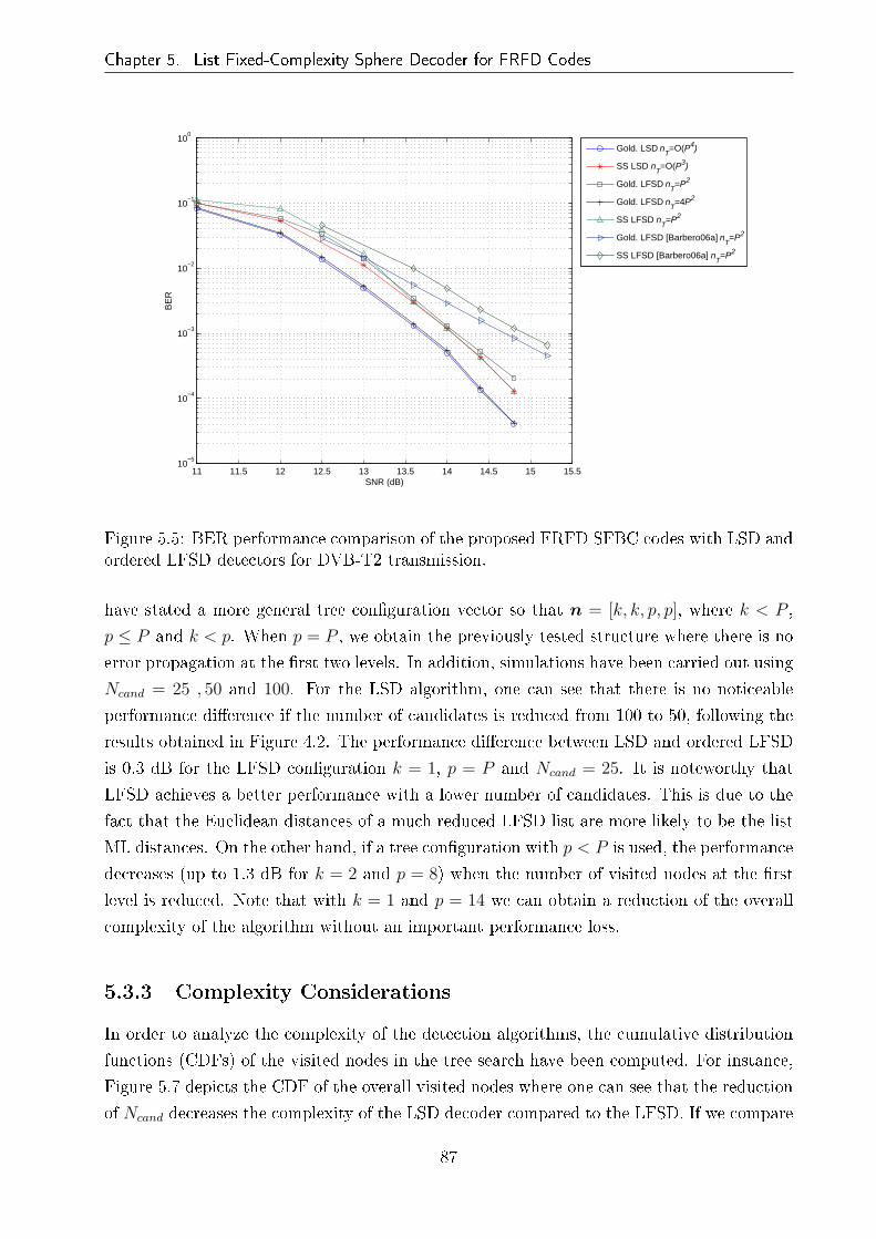
Chapter 5. List Fixed-Complexity Sphere Decoder for FRFD Codes
11 11.5 12 12.5 13 13.5 14 14.5 15 15.510
−5
10−4
10−3
10−2
10−1
100
SNR (dB)
BE
R
Gold. LSD n
T=O(P4)
SS LSD nT=O(P3)
Gold. LFSD nT=P2
Gold. LFSD nT=4P2
SS LFSD nT=P2
Gold. LFSD [Barbero06a] nT=P2
SS LFSD [Barbero06a] nT=P2
Figure 5.5: BER performance comparison of the proposed FRFD SFBC codes with LSD andordered LFSD detectors for DVB-T2 transmission.
have stated a more general tree con�guration vector so that n = [k, k, p, p], where k < P ,
p ≤ P and k < p. When p = P , we obtain the previously tested structure where there is no
error propagation at the �rst two levels. In addition, simulations have been carried out using
Ncand = 25 , 50 and 100. For the LSD algorithm, one can see that there is no noticeable
performance di�erence if the number of candidates is reduced from 100 to 50, following the
results obtained in Figure 4.2. The performance di�erence between LSD and ordered LFSD
is 0.3 dB for the LFSD con�guration k = 1, p = P and Ncand = 25. It is noteworthy that
LFSD achieves a better performance with a lower number of candidates. This is due to the
fact that the Euclidean distances of a much reduced LFSD list are more likely to be the list
ML distances. On the other hand, if a tree con�guration with p < P is used, the performance
decreases (up to 1.3 dB for k = 2 and p = 8) when the number of visited nodes at the �rst
level is reduced. Note that with k = 1 and p = 14 we can obtain a reduction of the overall
complexity of the algorithm without an important performance loss.
5.3.3 Complexity Considerations
In order to analyze the complexity of the detection algorithms, the cumulative distribution
functions (CDFs) of the visited nodes in the tree search have been computed. For instance,
Figure 5.7 depicts the CDF of the overall visited nodes where one can see that the reduction
of Ncand decreases the complexity of the LSD decoder compared to the LFSD. If we compare
87

Chapter 5. List Fixed-Complexity Sphere Decoder for FRFD Codes
12.5 13 13.5 14 14.5 15 15.510
−5
10−4
10−3
10−2
10−1
BE
R
SNR (dB)
LSD, N
cand=50
LSD, Ncand
=100
n=[1 1 16 16], Ncand
=50
n=[1 1 16 16], Ncand
=25
n=[2 2 8 8], Ncand
=25
n=[1 1 14 14], Ncand
=25
Figure 5.6: BER performance comparison between LSD and LFSD detection of Golden codesin the 2× 2 DVB-T2 system with 16-QAM modulation over a TU6 channel.
the LSD algorithm to the LFSD with n = [1 1 16 16], we observe that for Ncand = 100, 75%
of the LSD solutions are obtained visiting a lower number of nodes than with the LFSD. If
Ncand is reduced up to 50, this value rises to 95%. By using the tree con�guration of the
LFSD n = [1 1 14 14], the complexity di�erence between both decoders increases. In this
case, 50% and 90% of LSD tree searchs for Ncand = 100 and 50, respectively, will have a
higher complexity than the LFSD algorithm.
In Figure 5.7, we have been able to distinguish the sequential nature of the LSD tree
search and its variable complexity, and how the design of the LFSD maintains �xed the
search complexity allowing a practical hardware implementation. If we now calculate the
CDF per tree level, we can actually appreciate the complexity di�erences in terms of the
number of operations per level, being higher when such level is closer to the bottom. One can
observe in Figure 5.8(a) that for the lowest level i = 1, the LFSD decoder visits less nodes
than the LSD with Ncand = 100 for most of the channel realisations. When the number of
candidates of the LSD is reduced to 50, the 50% of the solutions for n = [1 1 14 14] and 10%
for n = [1 1 16 16] are reached with a lower number of visited nodes. As the level is closer
to the top of the tree, the di�erence becomes smaller, visiting almost the same number of
nodes at i = 4 with the LSD.
Regarding the number of operations in the LFSD search, let us denote md as the number
of multiplications required to calculate u2ii |si − zi|2, considering that u2
ii no longer needs to
be computed. The computed Euclidean distance has been `2 distance whereas many other
approximations can be found in the literature. Therefore, md = 3. In addition, let us
de�ne mc as the number of multiplications required for each complex product. A direct
implementation of the complex product has mc = 4. However, it can be reduced up to
88

Chapter 5. List Fixed-Complexity Sphere Decoder for FRFD Codes
0 500 1000 1500 20000
0.1
0.2
0.3
0.4
0.5
0.6
0.7
0.8
0.9
1
Total number of visited nodes
CD
F
LSD Ncand
=50
LSD Ncand
=100
LFSD n=[1 1 16 16]LFSD n=[1 1 14 14]
Figure 5.7: CDFs of the overall visited nodes in the LFSD and LSD detections of Goldencodes with 16-QAM modulation in the 2 × 2 DVB-T2 system over a TU6 channel withSNR=14.8 dB.
0 200 400 600 800 10000
0.1
0.2
0.3
0.4
0.5
0.6
0.7
0.8
0.9
1
Number of visited nodes for tree level i=1
CD
F
LSD Ncand
=50
LSD Ncand
=100
LFSD n=[1 1 16 16]LFSD n=[1 1 14 14]
(a) Tree level i = 1
0 200 400 600 800 10000
0.1
0.2
0.3
0.4
0.5
0.6
0.7
0.8
0.9
1
Number of visited nodes for tree level i=2
CD
F
LSD N
cand=50
LSD Ncand
=25
LFSD n=[1 1 16 16]LFSD n=[1 1 14 14]
(b) Tree level i = 2
0 50 100 150 200 250 3000
0.1
0.2
0.3
0.4
0.5
0.6
0.7
0.8
0.9
1
Number of visited nodes for tree level i=3
CD
F
LSD Ncand
=50
LSD Ncand
=25
LFSD n=[1 1 16 16]LFSD n=[1 1 14 14]
(c) Tree level i = 3
0 2 4 6 8 10 12 14 16 180
0.1
0.2
0.3
0.4
0.5
0.6
0.7
0.8
0.9
1
Number of visited nodes for tree level i=4
CD
F
LSD Ncand
=50
LSD Ncand
=25
LFSD n=[1 1 16 16]LFSD n=[1 1 14 14]
(d) Tree level i = 4
Figure 5.8: CDFs as a function of the number of visited nodes at levels i = 1, 2, 3 and 4 forthe LFSD and the LSD detections of Golden codes with 16-QAM modulation in the 2 × 2DVB-T2 system over a TU6 channel with SNR=14.8 dB.
89

Chapter 5. List Fixed-Complexity Sphere Decoder for FRFD Codes
mc = 3 with a expense of extra additions. Therefore, if we consider that the necessary
number of multiplications to compute one node at level i is
Nmult_node_i = md + (Q− i)mc, (5.12)
the number of multiplications required in the complete search stage can be then expressed
as
Nmult =
Q∑
i=1
(md
Q∏
j=i
nj + (Q− i)mc
Q∏
k=i+1
nk
), (5.13)
where the �rst term inside the sum represents the number of multiplications in the metric
calculation and the second term is related to the successive calculation of zi in (5.5). The
proposed algorithm has the same complexity in the tree search stage as in [Barbero06a,
Barbero08]. Nevertheless, unlike the Barbero's LFSD, where the ordering preprocessing
requires Q− 1 matrix inversion operations, the proposed algorithm only performs Q vector
norm calculation.
5.4 Chapter Summary
This chapter has presented a novel LFSD algorithm design for the detection of FRFD codes
with low complexity in future SFBC-enabled TDT systems. Due to the FRFD code design,
the ordering stage of the algorithm proposed by [Barbero06a] for spatial multiplexing MIMO
systems does not adjust to the SFBC channel structure. Through the study of the equiv-
alent channel matrices, a new channel ordering procedure has been developed improving
the previously introduced LFSD performance and achieving a close-to-optimal result with a
�xed-complexity, overcoming the sequential nature of the LSD tree search and its variable
complexity, which result in a problem for real hardware implementations. Hence, the design
of the proposed LFSD makes it possible to implement a parallel architecture of the algorithm
that can be fully pipelined and maintains �xed the search complexity.
The algorithm has been analyzed in a DVB-T2 framework through MATLAB simulations.
First of all, a trade-o� between complexity and performance has been found. Due to its �xed
complexity, LFSD provides a list of candidates which does not correspond to the list ML
given by the LSD. The reliability of the list will vary in accordance to the size of the tree
search (nT ) and the number of candidates (Ncand). Hence, a battery of simulations have
been carried out in order to observe the behavior of the algorithm for the Golden and the
low-complexity SS codes as a function of these two parameters with and without ordering
stage. As a result, we have proved that the ordering preprocessing stage results advantageous
for Golden codes due to their inherent symbol power distribution and that SS codes o�er a
90
Chapter 5. List Fixed-Complexity Sphere Decoder for FRFD Codes
good performance without any ordering. In addition, we can conclude that reduced Ncand
values o�er better performance when we decrease the size of the search, i.e. nT .
Once a Ncand value of 50 has been chosen, BER performance simulations have been pre-
sented as a function of SNR. We have observed that the computation of nT = 4P 2 Euclidean
distances o�ers almost the same performance as LSD. When it is reduced downto nT = P 2,
the performance is maintained close to the LSD with a loss of 0.4 dB. In these simulations,
we have also provided the comparison with respect to the LFSD in [Barbero06a], where a
gain of 0.75 dB is achieved. On the other hand, several tree search con�gurations have been
proposed to reduce the search complexity, being the most promising n = [1 1 14 14] with
Ncand = 25 since it maintains a similar performance as the previously stated con�gurations.
Last part of the chapter presents some complexity considerations of the proposed LFSD.
By paying attention to the CDFs of the visited nodes through the tree structure, we have
noticed the variable nature of the LSD algorithm. Even though the average �gures of the
LSD could be lower than LFSD for some con�gurations, CDF curves depict how the number
of visited nodes can become much greater for certain channel realisations, specially at last
levels of the tree where the required number of operations is higher. The proposed LFSD
allows us to overcome this problem with a feasible �xed complexity and close-to-optimal
results. Indeed, a lower overall complexity is required compared to the LFSD in [Barbero08]
due to the reduction of the number of operations at the proposed ordering stage.
91
Chapter 6
Summary and Conclusions
In this PhD dissertation, we have analyzed the behavior of multi-antenna diversity tech-
niques, speci�cally SFBCs, in DTV scenarios and proposed novel detection and decoding
designs in order to reduce the complexity at the receiver. As a starting point, the DVB-
T and DVB-T2 standards have been implemented in MATLAB as well as several MIMO
techniques. First of all, BER performance comparison of the state-of-the-art diversity tech-
niques have been carried out in Chapter 2 for both DVB-T and DVB-T2 systems over
common TDT propagation scenarios. As has been shown, Alamouti code-based OSFBC
presents better results in comparison to CDD since it obtains a performance gain similar
to MRC using transmit diversity, which results less expensive than a second antenna at the
receivers. This scheme obtains good performance in both �xed and mobile receptions when
signal are synchronized. However, the study of the distributed OSFBC behavior in SFN
networks shows a loss of the overall performance, reaching a critical limit, i.e. error �oor
over the QEF, if the delay is close to the GI length.
Chapters 3 and 4 are focused on the study of 2 × 2 FRFD SFBCs in last-generation
DTV systems through error-performance and detection complexity analyses. The use of
channel coding based on LDPCs involves a soft-output MAP detector which results in an
increase of the detection complexity. The reduction of that computational cost can be
achieved through the use of FRFD SFBCs, which have an inherent low detection complexity
at the cost of sacri�cing performance gain. Two FRFD SFBC codes have been chosen in
order to assess the mentioned statements. On one hand, the Golden code, which achieves
the maximal coding gain, and on the other hand, the low-complexity SS code with lower
performance. These codes have been implemented in a DVB-T2 framework since it includes
the last-generation technologies. Simulation results show a better performance than the
2× 2 DVB-T2 OSFBC for the same raw bit rate in Rayleigh channels. However, we obtain
an opposite behavior when propagation conditions are based on Ricean channels. FRFD
SFBCs can allow us to increase the data bit rate if low-complexity detection algorithms are
developed since the detection complexity grows exponentially as a function of the modulation
order and the number of coded symbols. For that purpose, LSD-based detection techniques
have been proposed in the literature. The complexity analysis of LSD algorithm showed
92

Chapter 6. Summary and Conclusions
that the detection stage can be performed with an average smaller number of operations.
Nevertheless, its variable complexity depending on the noise level and the channel conditions
and its sequential nature result in a problem from a practical point of view. As a result, a
�xed-complexity detector has been proposed in such a way that it can be fully pipelined in
a hardware implementation.
Starting from the concept of the LFSD for spatial multiplexing MIMO systems, a re-
design of the previously proposed algorithm has been carried out for FRFD SFBCs with
close-to-LSD performance. Due to the two-dimensional transmission of SFBCs, the ordering
procedure proposed for one-dimensional transmission in spatial multiplexing modes does not
take into account the correlation between subchannels. Therefore, the tree con�guration
and the subchannel ordering processes can be modi�ed reducing the necessary number of
operations at that stage and optimizing the performance of the algorithm. Simulation re-
sults proved the behavior of the algorithm compared to the LSD and the LFSD for spatial
multiplexing. On one hand, results have showed better performance than the LFSD for
spatial multiplexing. On the other hand, we have observed a performance close to the LSD
algorithm maintaining a reasonable �xed complexity which would make a realistic hardware
implementation feasible.
6.1 Thesis Contributions
The main contributions of this research work are the following:
• Performance comparison of the multi-antenna diversity techniques CDD, Alamouti
SFBC and MRC in �xed and mobile DVB-T reception environments.
• Analysis of diversity techniques included in the DVB-T2 standard over Rayleigh and
Ricean channels.
• Simulation-based analysis of the DVB-T and DVB-T2 self-interfered SISO reception
in SFN networks. This work was published in [Sobron09a, Sobrón09b].
• Performance study of the distributed DVB-T2 MISO scheme reception in SFN net-
works depending on attenuations and delays of the transmitted signals. The work was
published in [Sobrón10d].
• Development of a soft MAP detection approach for FRFD SFBCs in DVB-T2-based
systems according to candidate lists. Optimization of the soft method �nding the
trade-o� between number of candidates and performance.
• Performance comparison of Golden code, low-complexity SS code and DVB-T2 SFBC
in a DVB-T2 framework over TDT scenarios. Published in [Sobron10c].
93

Chapter 6. Summary and Conclusions
• Novel design of an ordering algorithm for the LFSD detection of FRFD codes, specially
Golden codes. Optimization analysis of the LFSD algorithm as a function of the tree
con�guration and the number of candidates. Comparitive analysis of the performance
and complexity of the proposed LFSD and the LSD in TDT environments. This work
has been submitted for its possible publication in [Sobron10a, Sobron10b].
6.2 Suggestions for Further Research
Many issues described in this PhD dissertation can be addressed in the future as an im-
provement and extension of the current work. These are some of the suggestions for further
research:
• As we have seen for the DVB-T2 MISO scheme, a loss of performance appears when
transmitted signals are delayed between them. Other works have stated this problem
with FRFD codes giving solutions such as 3D schemes [Nasser08a]. Therefore, an
extension of those works can be carried out focusing on a detection point of view.
• From our best knowledge, FRFD STBC/SFBC designs have been usually optimized as-
suming Rayleigh channel conditions. Therefore, the design of FRFD SFBC for Ricean
channels could be stated.
• Real-valued implementation of the proposed LFSD algorithm. In this work, a complex-
valued version has been implemented. However, using a real-valued implementation,
the tree search has more degrees of freedom and as a consequence, an improvement of
performance might be possible. For that purpose, a review of the ordering procedure
should be necessary.
• There exist multiple designs of FRFD SFBC codes apart from those which this research
work has been addressed to. Therefore, the application of the proposed ordering and
LFSD algorithm to other existing FRFD codes could allow us to obtain a more general
framework for SFBC comparison.
94

Appendix A
Publications
The following papers have been published or are under preparation for publication in refereed
journal and conference proceedings. Those marked by † are directly related to the research
work of this thesis.
Book Chapter:
• M. Mendicute, I. Sobrón, L. Martínez and P. Ochandiano, �Digital Video� chap. DVB-
T2: New Signal Processing Algorithms for a Challenging Digital Video Broadcasting
Standard, pp. 185-206, InTech, Feb. 2010. †
Journal paper:
• I. Sobrón, M. Barrenechea, P. Ochandiano, L. Martínez, M. Mendicute and J. Altuna,
�Low-Complexity Detection of Space-Frequency Block Codes in LDPC-Based OFDM
Systems�, submitted to IEEE Transactions on Communications (under review). †
International conference papers:
• M. Mendicute, I. Sobrón, J. Del Ser, P. Prieto and R. Isasi, �Design, simulation and
implementation of a channel equalizer for DVB-T on-channel repeaters�, in 3rd IARIA
International Conference on Systems and Networks Communications (ICSNC '08),
Silema, Malta, Oct. 2008.
• I. Sobrón, M. Mendicute, L. Martínez and P. Ochandiano, �Impact of self interference in
DVB-T2 broadcasting single frequency networks�, in Proc. 9th International Workshop
on Electronics, Control, Modelling, Measurement and Signals (ECMS '09), pp. 97-103,
Mondragon, Spain, Jul. 2009. †
95

Appendix A. Publications
• L. Martínez, J. Robert, H. Meuel, I. Sobrón and M. Mendicute, �Improved Robustness
for Channel Estimation without Pilots for DVB-T2�, in Proc. IEEE International
Symposium on Broadband Multimedia Systems and Broadcsting (BMSB '10), pp. 1-5,
Shangai, China, Mar. 2010.
• I. Sobrón, M. Mendicute and J. Altuna, �Full-Rate Full-Diversity Space-Frequency
Block Coding for Digital TV Broadcasting�, in Proc. 18th EURASIP European Signal
Processing Conference (EUSIPCO '10), pp. 1514-1518, Aalborg, Denmark, Aug. 2010.
†
• P. Ochandiano, I. Sobrón, L. Martínez, M. Mendicute and J. Altuna, �Analysis of
ICI compensation for DVB-T2�, in Proc. 7th International Symposium on Wireless
Communication Systems (ISWCS '10), pp. 427-430, York, United Kingdom, Sep.
2010.
• I. Sobrón, M. Barrenechea, P. Ochandiano, L. Martínez, M. Mendicute and J. Altuna,
�Low-Complexity Detection of Golden Codes in LDPC-Coded OFDM Systems�, sub-
mitted to IEEE International Conference on Acoustics, Speech and Signal Processing
(ICASSP '11), Prague, Czech Republic, May 2011 (under review). †
National conference papers:
• V. Atxa, I. Sobrón, J.M. Zabalegui, J. Altuna, M. Mendicute and I. Marcos, �Análisis
sobre la ecualización de canal en la cabecera de un gap-�ller doméstico para DVB-T�,
in Proc. XX Simposium Nacional de la Unión Cientí�ca Internacional de Radio (URSI
'07), La Laguna, Spain, Sep. 2007.
• M. Mendicute, P. Prieto, I. Sobrón, J. M. Zabalegui and R. Isasi, �Diseño, simulación
e implementación de un ecualizador de canal para gap-�llers de DVB-T�, in Proc.
XXI Simposium Nacional de la Unión Cientí�ca Internacional de Radio (URSI '08),
Madrid, Spain, Set. 2008.
• I. Sobrón, J. Del Ser and M. Mendicute, �Estudio y simulación de repetidores rege-
nerativos y no regenerativos en redes de difusión DVB-T�, in Proc. XXI Simposium
Nacional de la Unión Cientí�ca Internacional de Radio (URSI '08), Madrid, Spain,
Set. 2008.
• I. Sobrón, P. Ochandiano, L. Martínez, M. Mendicute and J. Altuna, �Análisis de
robustez de DVB-T2 en redes SFN�, in Proc. XXII Simposium Nacional de la Unión
Cientí�ca Internacional de Radio (URSI '09), Cantabria, Spain, Sep. 2009. †
96

Appendix A. Publications
• L. Martínez, I. Sobrón, P. Ochandiano, M. Mendicute and J. Altuna, �Estimación de
canal para transmisión multiantena y recepción móvil en DVB-T2�, in Proc. XXIII
Simposium Nacional de la Unión Cientí�ca Internacional de Radio (URSI '10), Bilbao,
Spain, Sep. 2010.
• P. Ochandiano, I. Sobrón, L. Martínez, M. Mendicute and J. Altuna, �Detección itera-
tiva en receptores DVB-T2�, in Proc. XXIII Simposium Nacional de la Unión Cientí�ca
Internacional de Radio (URSI '10), Bilbao, Spain, Sep. 2010.
• I. Sobrón, P. Ochandiano, L. Martínez, M. Mendicute and J. Altuna, �Transmisión
SFBC distribuida en redes SFN de DVB-T2�, in Proc. XXIII Simposium Nacional de
la Unión Cientí�ca Internacional de Radio (URSI '10), Bilbao, Spain, Sep. 2010. †
97

References
[Al-Semari97] S. Al-Semari and T. Fuja, �I-Q TCM: reliable communication over the
Rayleigh fading channel close to the cut-o� rate�, IEEE Transactions on
Information Theory, vol. 43, no. 1, 250�262, January 1997.
[Alamouti98] S. Alamouti, �A simple transmit diversity technique for wireless commu-
nications�, IEEE Journal on Selected Areas in Communications, vol. 16,
no. 8, 1451 � 1458, October 1998.
[ARIB01] ARIB, �Transmission System for Digital Terrestrial Television Broadcast-
ing STD-B31 v1.0�, 2001.
[ATSC05] ATSC, �ATSC Digital Television Standard (A/53) Revision E, with
Amendments No. 1 and 2�, December 2005.
[Barbero06a] L. Barbero, Rapid prototyping of a �xed-complexity sphere decoder and
its application to iterative decoding of turbo-MIMO systems, Ph.D. thesis,
University of Edinburgh, 2006.
[Barbero06b] L. Barbero and J. Thompson, �Performance analysis of a �xed-complexity
sphere decoder in high-dimensional MIMO systems�, in Proceedings IEEE
International Conference on Acoustics, Speech and Signal Processing
(ICASSP'06), 2006.
[Barbero08] L. Barbero and J. Thompson, �Extending a �xed-complexity sphere de-
coder to obtain likelihood information for turbo-MIMO systems�, IEEE
Transactions on Vehicular Technology, vol. 57, no. 5, 2804 � 14, Septem-
ber 2008.
[Bel�ore04] J. Bel�ore, G. Rekaya, and E. Viterbo, �The golden code: A 2 x 2 full-
rate space-time code with non-vanishing determinants�, in 2004 IEEE
International Symposium on Information Theory, Proceedings, p. 308,
IEEE, 2004.
98

References
[Bello63] P. A. Bello, �Characterization of randomly time-invariant linear chan-
nels�, IEEE Transactions on Communications Systems, vol. CS-11, 360�
393, December 1963.
[Bolcskei00] H. Bolcskei and A. J. Paulraj, �Space-Frequency Coded Broadband
OFDM Systems�, in IEEE WCNC, vol. 1, September 2000.
[Boutros03] J. Boutros, N. Gresset, L. Brunel, and M. Fossorier, �Soft-Input Soft-
Output Lattice Sphere Decoder for Linear Channels�, in Proc. IEEE
Global Telecommunications Conference (GLOBECOM '03), vol. 3, pp.
1583�1587, San Francisco, CA, Dec. 2003.
[Burg05] A. Burg, M. Borgmann, M. Wenk, M. Zellweger, W. Fichtner, and
H. Bolcskei, �VLSI Implementation of MIMO detection using the sphere
decoding algorithm�, IEEE Journal of Solid-State Circuits, vol. 40, no. 7,
1566 � 1576, 2005.
[Clarke89] R. H. Clarke, �A statistical theory of mobile radio reception�, Bell System
Technical Journal, vol. 47, 957�1000, 1989.
[Conway88] J. H. Conway and N. J. A. Sloane, Sphere Packings, Lattices and Groups,
Springer-Verlag, New York, 1988.
[Corre05] Y. Corre, A. Fluerasu, E. Hamman, L. Houel, Y. Lostanlen, and A. Sibile,
�Result of a measurement campaign of DVB-T signals with an indoor two
antennas diversity receiver�, Document td(05) 099, COST 207, Lisbon
(Portugal), November 2005.
[COST20789] COST207, �Digital land mobile radio communications (�nal report)�,
Tech. rep., Commision of the European Communities, Directorate Gen-
eral Telecommunications, Information Industries and Innovation, 1989.
[Cox73] D. C. Cox, �910 MHz Urban Mobile Radio Propagation: Multipath Char-
acteristics in New York City�, IEEE Transactions in Vehicular Technol-
ogy, vol. 22, no. 4, 104�110, November 1973.
[Dai05] Y. Dai, S. Sun, and Z. Lei, �A comparative study of QRD-M detection
and sphere decoding for MIMO-OFDM systems�, in 16th IEEE Interna-
tional Symposium on Personal Indoor and Mobile Radio Communications
(PIMRC 2005), pp. 186�190, September 2005.
[Damen03] M. O. Damen, H. El Gamal, and G. Caire, �On maximum-likelihood
detection and the search for the closest lattice point�, IEEE Transactions
on Information Theory, vol. 49, no. 10, 2389 � 2402, 2003.
99

References
[Dammann01] A. Dammann and S. Kaiser, �Standard conformable antenna diversity
techniques for OFDM and its application to the DVB-T system�, in Pro-
ceedings IEEE Global Telecommunications Conference, vol. 5, pp. 3100 �
3105, San Antonio, TX, 2001.
[Dammann07] A. Dammann, R. Raulefs, and S. Plass, �Soft cyclic delay diversity and its
performance for DVB-T in ricean channels�, in GLOBECOM, pp. 4210
� 4214, Washington, DC, United States, 2007.
[Dammann09] A. Dammann and R. Raulefs, �Evaluation of diversity gains for the next
generation of terrestrial DVB�, in Proceedings 14th International OFDM-
Workshop (InOWo 2009), Hamburg, Germany, 2009.
[deJong05] Y. L. C. de Jong and T. J. Willink, �Iterative tree search detection
for MIMO wireless systems�, IEEE Transactions on Communications,
vol. 53, no. 6, 930�935, June 2005.
[Di Bari08] R. Di Bari, M. Bard, Y. Zhang, K. M. Nasr, J. Cosmas, K. K. Loo,
R. Nilavalan, H. Shirazi, and K. Krishnapillai, �Laboratory Measura-
ment Campaign of DVB-T Signal With Transmit Delay Diversity�, IEEE
Transactions on Broadcasting, vol. 54, no. 3, 532�541, September 2008.
[Di Bari09] R. Di Bari, M. Bard, A. Arrinda, P. Ditto, J. Cosmas, K. Loo, and
R. Nilavalan, �Rooftop and Indoor reception with transmit diversity ap-
plied to DVB-T Networks: a long term measurement campaign�, in IEEE
International Symposium on Broadband Multimedia Systems and Broad-
casting, Bilbao, May 2009.
[DVB09] DVB, �Implementation guidelines for a second generation digital terres-
trial television broadcasting system (DVB-T2)�, Document A133, Febru-
ary 2009.
[ETSI97] ETSI, �Digital video Broadcasting (DVB); Framing structure, channel
coding and modulation for digital terrestrial television (DVB-T) ETS
EN 300 744�, March 1997.
[ETSI04] ETSI, �Digital Video Broadcasting (DVB); Transmission System for
Handheld Terminals (DVB-H). EN 302.304 V1.1.1�, November 2004.
[ETSI06] ETSI, �Digital Video Broadcasting (DVB); Second generation framing
structure, channel coding and modulation systems for Broadcasting, In-
teractive Services, News Gathering and other broadband satellite appli-
cations EN 302 307 V1.1.2�, June 2006.
100

References
[ETSI09] ETSI, �Digital Video Broadcasting (DVB); Frame structure channel cod-
ing and modulation for a second generation digital terrestrial television
broadcasting system (DVB-T2). ETSI EN 302 755 V1.1.1�, September
2009.
[EVS06] EVS, �Mobile and Portable DVB-T/H Radio Access. Part 1: Interface
Speci�cations.�, EVS-EN 62002-1:2006, 2006.
[Fincke85] U. Fincke and M. Pohst, �Improved methods for calculating vectors of
short length in a lattice, including a complexity analysis�, Mathematics
of Computation, vol. 44, no. 170, 463 � 71, April 1985.
[Fluerasu05] A. Fluerasu, A. Sibile, Y. Corre, Y. Lostanlen, L. Houel, and E. Hamman,
�A measurement campaign of spatial, angular, and polarization diver-
sity reception of DVB-T�, Document TD (05) 019, COST 273, Bologna
(Italy), January 2005.
[Foschini96] G. J. Foschini, �Layered Space-Time Architecture for Wireless Communi-
cation in a Fading Environment When Using Multi-Element Antennas�,
Bell Labs Technical Journal, vol. 1, no. 2, 41�59, Oct. 1996.
[Foschini98] G. Foschini and M. Gans, �On limits of wireless communications in a
fading environment when using multiple antennas�, Wireless Personal
Communications Magazine - Kluwer Academic, vol. 6, no. 3, 311 � 335,
1998.
[Gallager63] R. G. Gallager, �Low Density Parity Check Codes�, in Research Mono-
graph Series, 21, MIT Press, Cambridge, Mass., July 1963.
[García-Lozano10] M. García-Lozano, S. Ruiz-Boqué, and F. Minerva, �Static Delays Op-
timization to Reduce Self-Interference in DVB-T Networks�, in IEEE
International Symposium on Broadband Multimedia Systems and Broad-
casting (BMSM), 2010.
[Gesbert03] D. Gesbert, M. Sha�, D.-s. Shiu, P. J. Smith, and A. Naguib, �From
Theory to Practice: An Overview of MIMO Space Time Coded Wireless
Systems�, IEEE Journal on Selected Areas in Communications, vol. 21,
no. 3, 281�302, April 2003.
[Gomez-Calero09] C. Gomez-Calero, L. Cuellar, L. de Haro, and R. Martinez, �A 2 x 2 novel
MIMO testbed for DVB-T2 systems�, in IEEE International Symposium
on Broadband Multimedia Systems and Broadcasting. BMSB '09., June
2009.
101

References
[Guena04] A. Guena, D. Zapparata, A. Sibille, and G. Pousset, �Mobile diversity
reception of DVB-T signals using roof or window antennas�, Document
TD (04) 014, COST 273, Athens (Greece), January 2004.
[Guey96] J. Guey, M. Fitz, M. Bell, and W. Kuo, �Signal design for transmitter
diversity wireless communication systems over Rayleigh fading channels�,
in 1996 IEEE 46th Vehicular Technology Conference, Proceedings - Mo-
bile Technology for the Human Race (VTC 96) , vol. 1-3, pp. 136�140,
IEEE, Vehicular Technol Soc; IEEE, Atlanta Sect, I E E E, 1996.
[Guo06] Z. Guo and P. Nilsson, �Algorithm and implementation of the K-best
sphere decoding for MIMO detection�, IEEE Journal on Selected Areas
of Communications, vol. 24, no. 3, 491�503, March 2006.
[Hagenauer96] J. Hagenauer, E. O�er, and L. Papke, �Iterative decoding of binary block
and convolutional codes�, IEEE Transactions on Information Theory,
vol. 42, no. 2, 429 � 45, 1996.
[Hakala07] P. Hakala and H. Himmanen, �Evaluation of DVB-H Broadcast Systems
Using New Radio Channel Models�, Tech. Rep. 817, TUCS Turku Centre
for Computer Science, March 2007.
[Hassibi02] B. Hassibi and B. Hochwald, �High-rate codes that are linear in space and
time�, IEEE Transactions on Information Theory, vol. 48, no. 7, 1804 �
24, 2002.
[Hassibi05] B. Hassibi and H. Vikalo, �On the Sphere-Decoding Algorithm I. Ex-
pected Complexity�, IEEE Trans. Signal Processing, vol. 53, no. 8, 2806�
2818, Aug. 2005.
[Hochwald03] B. Hochwald and S. ten Brink, �Achieving near-capacity on a multiple-
antenna channel�, IEEE Transactions on Communications, vol. 51, no. 3,
389 � 99, 2003.
[Hoeher92] P. Hoeher, �A Statistical Discrete Time Model for the WSSUS Multipath
Channel�, IEEE Transactions on Vehicular Technology, vol. 41, no. 4,
461�468, November 1992.
[Horseman03] T. Horseman, J. Webber, M. Abdul-Aziz, R. Piechocki, M. Beach, A. Nix,
and P. Fletcher, �A software and hardware evaluation of revolutionary
Turbo MIMO OFDM schemes for 5GHz WLANs�, in Proc. 57th IEEE
Vehicular Technology Conference (VTC '03-Spring), vol. 4, pp. 2788�
2792, Seoul, Korea, Apr. 2003.
102

References
[ISO00] ISO, �ISO/IEC 13818: Standard MPEG-2�, 2000.
[ist07] �Telematic link: http://dea.brunel.ac.uk/pluto/publications.php�, 2007.
[ITU06] R. S. G. ITU, �Preliminary Report on the Channel Model Development
for Hand Held Reception�, Document 6E/335-E, March 2006.
[Jakes94] W. C. Jakes, Microwave Mobile Communications, Wiley-IEEE Press,
May 1994.
[Jaldén07] J. Jaldén, L. G. Barbero, B. Ottersten, and J. S. Thompson, �Full Di-
versity Detection in MIMO Systems with a Fixed-Complexity Sphere
Decoder�, in IEEE International Conference on Acoustics, Speech, and
Signal Processing (ICASSP �07), Honolulu, Hawaii, USA, April 2007.
[JTC93] JTC, �Final Report on RF Channel Characterization�,
JTC(AIR)/93.09.23-238R2, September 1993.
[Kaiser00] S. Kaiser, �Spatial transmit diversity techniques for broadband OFDM
systems�, in Proceedings IEEE Global Telecommunication Conference,
pp. 1824�1828, November 2000.
[Kyro07] M. Kyro, Multi-Element Antenna for DVB-H Terminal, Master's thesis,
Helsinki University of Technology, October 2007.
[Lee06] J. Lee and S.-C. Park, �Novel techniques of a list sphere decoder for high
throughput�, in Proc. International Conference on Advanced Communi-
cation Technology (ICACT 06), pp. 1785�1787, Phoenix Park, Korea,
February 2006.
[Lu00] B. Lu and X. Wang, �Space-time code design in OFDM systems�, in
IEEE Global Telecommunications Conference (GLOBECOM '00), vol. 2,
pp. 1000�1004, 2000.
[Ma03] X. Ma and G. B. Giannakis, �Full-diversity full-rate complex-�eld space-
time coding�, IEEE Transactions on Signal Processing, vol. 51, no. 11,
2917�2930, 2003.
[Mannino08] C. Mannino, F. Rossi, A. Sassano, and S. Smriglio, �Time O�set Opti-
mization in Digital Broadcasting�, Discrete Applied Mathematics (Else-
vier), vol. 3, no. 156, 339�351, 2008.
[MBRAI07] E. MBRAI, �Mobile and portable DVB-T/H radio access - Part 1: In-
terface speci�cation�, EICTA MBRAI 2.0, June 2007.
103
References
[Mendicute10] M. Mendicute, I. Sobrón, L. Martínez, and P. Ochandiano, Digital Video,
chap. DVB-T2: New Signal Processing Algorithms for a Challenging
Digital Video Broadcasting Standard, pp. 185�206, InTech, February
2010.
[Mitchell06] J. D. Mitchell, P. N. Moss, and M. J. Thorp, �A dual polarisation MIMO
broadcast TV system�, British Broadcasting Corporation (BBC), Decem-
ber 2006.
[Morgade09] J. Morgade, J. Pérez, J. Basterrechea, A. Arrinda, and P. Angueira, �Op-
timization of the Coverage Area for DVBT- Single Frequency Networks
Using a Particle Swarm Based Method�, in IEEE Vehicular Technology
Conference Spring (VTC 2009 Spring), Barcelona (Spain), April 2009.
[Moss08] P. N. Moss, �2-by-2 MIMO portable reception channel model for dual-
polar terrestrial transmission�, British Broadcasting Corporation (BBC),
July 2008.
[Motivate00] Motivate, �Deliverable 06: Reference Receivers Conditions for Mobile
Reception�, AC 318 Motivate., January 2000.
[Nasser08a] Y. Nasser, J.-F. Helard, and M. Crussiere, �3D MIMO scheme for broad-
casting future digital TV in single-frequency networks�, Electronics Let-
ters, vol. 11, no. 13, 829�830, June 2008.
[Nasser08b] Y. Nasser, J. Hélard, and M. Crussière, �System Level Evaluation of
Innovative Coded MIMO-OFDM Systems for Broadcasting Digital TV�,
International Journal of Digital Multimedia Broadcasting, vol. 2008, 12,
2008.
[Nasser08c] Y. Nasser, J.-F. Hélard, M. Crussiere, and O. Pasquero, �E�cient
MIMO-OFDM schemes for future terrestrial digital TV with unequal
received powers�, in IEEE International Conference on Communications
(ICC'08), pp. 2021�2027, Beijing, China, May 2008.
[Nour08] C. A. Nour and C. Douillard, �Rotated QAM Constellations to Improve
BICM Performance for DVB-T2�, in Spread Spectrum Techniques and
Applications, 2008. ISSSTA apos;08. IEEE 10th International Sympo-
sium on, 25-28, pp. 354�359, August 2008.
[Paredes07] J. Paredes, A. B. Gershman, and M. Gharavi-Alkhansari, �A 2 x 2 space-
time code with non-vanishing determinants and fast maximum likelihood
104
References
decoding�, in IEEE International Conference on Acoustics, Speech, and
Signal Processing, Pts 1-3, vol. 2, pp. 877�880, IEEE Signal Proc Soc,
IEEE, 2007.
[Paredes08] J. M. Paredes, A. B. Gershman, and M. Gharavi-Alkhansari, �A New
Full-Rate Full-Diversity Space-Time Block Code With Nonvanishing De-
terminants and Simpli�ed Maximum-Likelihood Decoding�, IEEE Trans-
actions on Signal Processing, vol. 56, no. 6, 2461�2469, June 2008.
[Park05] S. Y. Park, S. K. Choi, and C. G. Kang, �Complexity-reduced iterative
MAP receiver for spatial multiplexing systems�, IEE Proc. on Commu-
nications, vol. 152, no. 4, 432�438, August 2005.
[Patzold02] M. Patzold, Mobile Fading Channels, John Wiley and Sons, 2002.
[Paulraj03] A. Paulraj, R. Nabar, and D. Gore, Introduction to Space-Time Wireless
Communications, Cambridge University Press, Cambridge, UK, 2003.
[Penttinen08] J. T. J. Penttinen, �The SFN gain in non-interfered and interfered DVB-
H networks�, in The Fourth International Conference on Wireless and
Mobile Communications, pp. 294�299, Athens, Greece, July 2008.
[Proakis95] J. G. Proakis, Digital Communications, McGraw-Hill, 3rd edn., 1995.
[Radosavljevic09] P. Radosavljevic, Y. Guo, and J. Cavallaro, �Probabilistically bounded
soft sphere detection for MIMO-OFDM receivers: algorithm and sys-
tem architecture�, IEEE Journal on Selected Areas in Communications,
vol. 27, no. 8, 1318 � 30, 2009.
[Rinne00] J. Rinne, �Some elementary suboptimal diversity reception schemes for
DVB-T in mobile conditions�, IEEE Transactions on Consumer Elec-
tronics, vol. 46, no. 3, 847 � 850, 2000.
[Robertson95] P. Robertson, E. Villebrun, and P. Hoeher, �A Comparison of Optimal
and Sub-Optimal MAP Decoding Algorithms Operating in the Log Do-
main�, in Proc. IEEE International Conference on Communications (ICC
'95), vol. 2, pp. 1009�1013, Seattle, WA, Jun. 1995.
[SAC06] SAC, �GB20600-2006 Framing structure, Channel coding and modula-
tion for digital television terrestrial broadcasting system�, 2006.
105

References
[Samuel07] M. Samuel and M. P. Fitz, �Reducing The Detection Complexity By
Using 2x2 Multi-Strata Space-Time Codes�, in IEEE International Sym-
posium on Information Theory. ISIT 2007., pp. 1946�1950, Nice, June
2007.
[Sanchez-Varela00] M. Sanchez-Varela and M. Garcia-Sanchez, �Analysis of polarization di-
versity at digital TV indoor receivers�, IEEE Transactions on Broadcast-
ing, vol. 46, no. 4, 233 � 239, 2000.
[Sanchez-Varela01] M. Sanchez-Varela, M. García-Sánchez, L. Lukama, and D. J. Edwards,
�Spatial Diversity Analysis for Digital TV Systems�, IEEE Transactions
on Broadcasting, vol. 47, no. 3, 198�206, September 2001.
[Santella04] G. Santella, R. De Martino, and M. Ricchiuti, �Single Frequency Network
(SFN) planning for digital terrestrial television and radio broadcast ser-
vices: the Italian frequency plan for T-DAB�, in Vehicular Technology
Conference. VTC 2004-Spring. 2004 IEEE 59th, vol. 4, pp. 2307�2311,
May 2004.
[Schnorr91] C.-P. Schnorr and M. Euchner, �Lattice basis reduction: improved prac-
tical algorithms and solving subset sum problems�, in Proceedings Fun-
damentals of Computation Theory (FCT'91), pp. 68�85, 1991.
[Sezginer07] S. Sezginer and H. Sari, �Full-rate full-diversity 2x2 space-time codes
of reduced decoder complexity�, IEEE Communications Letters, vol. 11,
no. 12, 973�975, DEC 2007.
[Sezginer09] S. Sezginer, H. Sari, and E. Biglieri, �On High-Rate Full-Diversity 2 x
2 Space-Time Codes with Low-Complexity Optimum Detection�, IEEE
Transactions on Communications, vol. 57, no. 5, 1532�1541, MAY 2009.
[Shannon48] C. Shannon, �A mathematical theory of communications�, Bell Labs
Technical Journal, vol. 27, 379�423, 1948.
[Sobron09a] I. Sobron, M. Mendicute, L. Martinez, and P. Ochandiano, �Impact of
self interference in DVB-T2 broadcasting single frequency�, in 9th Inter-
national Workshop on Electronics, Control, Modelling, Measurement and
Signals, ECMS 2009., Mondragon, Spain, July 2009.
[Sobrón09b] I. Sobrón, P. Ochandiano, L. Martínez, M. Mendicute, and J. Altuna,
�Análisis de robustez de DVB-T2 en redes SFN�, in Proc. XXII Simpo-
sium Nacional de la Unión Cientí�ca Internacional de Radio (URSI '09),
Cantabria (Spain), September 2009.
106

References
[Sobron10a] I. Sobron, M. Barrenechea, P. Ochandiano, L. Maritinez, M. Mendicute,
and J. Altuna, �Low-Complexity Detection of Space-Frequency Block
Codes in LDPC-Based OFDM Systems�, August 2010.
[Sobron10b] I. Sobron, M. Barrenechea, P. Ochandiano, L. Martínez, M. Mendicute,
and J. Altuna, �Low-Complexity Detection of Golden Codes in LDPC-
Coded OFDM Systems�, October 2010.
[Sobron10c] I. Sobron, M. Mendicute, and J. Altuna, �Full-Rate Full-Diversity Space-
Frequency Block Coding for Digital TV Broadcasting�, in The 18th Eu-
ropean Signal Processing Conference (EUSIPCO-2010), Aalborg, Den-
mark, August 2010.
[Sobrón10d] I. Sobrón, P. Ochandiano, L. Martínez, M. Mendicute, and J. Altuna,
�Transmisión SFBC distribuida en redes SFN de DVB-T2�, in Proc.
XXIII Simposium Nacional de la Unión Cientí�ca Internacional de Ra-
dio (URSI '10), Bilbao, Spain, September 2010.
[Sumii05] K. Sumii, T. Nishimura, T. Ohgane, and Y. Ogawa, �A simpli�ed itera-
tive processing of soft MIMO detector and turbo decoder in a spatially
multiplexed system�, in Proc. 61st IEEE Vehicular Technology Confer-
ence (VTC 05-Spring), vol. 2, pp. 882�886, Stockholm, Sweeden, May
2005.
[Surendra Raju04] M. Surendra Raju, A. Ramesh, and A. Chockalingam, �LLR based BER
Analysis of Orthogonal STBCs using QAM on Rayleigh Fading Chan-
nels�, in Proc. IEEE PIMRC'2004, Barcelona, September 2004.
[Tarokh98] V. Tarokh, N. Seshadri, and A. R. Calderbank, �Space-time codes for
high data rate wireless communication: Performance criterion and code
construction�, IEEE Transactions on Information Theory, vol. 44, 744�
765, March 1998.
[Tarokh99] V. Tarokh, H. Jafarkhani, and A. Calderbank, �Space-time block codes
from orthogonal designs�, IEEE Transactions on Information Theory,
vol. 45, no. 5, 1456 � 1467, 1999.
[Telatar99] I. E. Telatar, �Capacity of multi-antenna gaussian channels�, European
Transactions on Telecommunications, vol. 10, no. 6, 585�595, Nov. 1999.
[Tirkkonen00] O. Tirkkonen, A. Boariu, and A. Hottinen, �Minimal nonorthogonality
rate 1 space-time block code for 3+ tx antennas�, in IEEE International
Symposium of Spread Spectrum Technology, pp. 429�432, 2000.
107

References
[Tirkkonen02] A. Tirkkonen and R. Kashaev, �Combined information and performance
optimization of linear MIMO modulations�, in Proceedings 2002 IEEE
International Symposium on Information Theory, pp. 76 �, Piscataway,
NJ, USA, 2002.
[Vikalo04] H. Vikalo, B. Hassibi, and T. Kailath, �Iterative Decoding for MIMO
Channels Via Modi�ed Sphere Decoding�, IEEE Trans. Wireless Com-
mun., vol. 3, no. 6, 2299�2311, Nov. 2004.
[Viterbo93] E. Viterbo and E. Biglieri, �A Universal Decoding Algorithm for Lattice
Codes�, in Proc. Quatorzieme Colloque GRETSI (GRETSI '93), vol. 1,
pp. 611�614, Juan Les Pins, France, Sep. 1993.
[Wittneben93] A. Wittneben, �A new bandwidth e�cient transmit antenna modulation
diversity scheme for linear digital modulation�, in Proceedings IEEE In-
ternational Conference on Communications (ICC 1993), pp. 1630�1634,
Geneve, Switzerland, May 1993.
[Wolniansky98] P. Wolniansky, G. J. Foschini, G. Golden, and R. Valenzuela, �V-BLAST:
An architecture for realizing very high data rates over the rich-scattering
wirelss channel�, in Proceedings URSI International Symposium on Sig-
nals, Systems and Electronics (ISSSE'98), pp. 295�300, September 1998.
[Yao03] H. Yao and G. W. Wornell, �Achieving the the full MIMO diversity-
multiplexing frontier with rotation based space-time codes�, in Allerton
Conference of Communication, Control and Computing, Monticelo, Oc-
tober 2003.
[Zhang07] Y. Zhang, J. Cosmas, K.-K. Loo, M. Bard, and R. Bari, �Analysis of
cyclic delay diversity on DVB-H systems over spatially correlated chan-
nel�, IEEE Transactions on Broadcasting, vol. 53, no. 1, 247 � 254, 2007.
[Zhang08] Y. Zhang, C. H. Zhang, J. Cosmas, K. K. Loo, T. Owens, R. D. Bari,
Y. Lostenlan, and M. Bard, �Analysis of DVB-H Network Coverage with
the Application of Transmit Diversity�, IEEE Transactions on Broad-
casting, vol. 54, 568�577, 2008.
[Zheng03] L. Zheng and D. N. C. Tse, �Diversity and multiplexing: a fundamental
tradeo� in multiple antenna channels�, IEEE Transactions on Informa-
tion Theory, vol. 49, no. 5, 1073�1096, May 2003.
108


![Implementation of Multi-Standard Video Decoding Algorithms ... Papers/with … · decoding on a heterogeneous coarse-grained reconfigurable multimedia processor REMUS [10]. In order](https://static.documents.pub/doc/80x56/5ead74ed0bfd2955731cf502/implementation-of-multi-standard-video-decoding-algorithms-paperswith-decoding.jpg)


