Page 1
Detection of Denial of Service Attack
Through Network Traffic Analysis
Thesis submitted in partial fulfilment of the requirements for the degree of
Bachelors of Technology
in
Computer Science and Engineering
Anurag Varma
111CS061
Under supervision of
Professor S K Jena
Department of Computer Science and Engineering
National Institute of Technology Rourkela
Rourkela, Odisha, 769 008, India
Page 2
Declaration by Student
I certify that
The work enclosed in this thesis has been done by me under the
supervision of my project guide.
The work has not been submitted to any other institute for any degree or
diploma.
I have confirmed to the norms and guidelines given in the Ethical Code of
Conduct of National Institute of Technology, Rourkela.
Whenever I have adopted materials (data, theoretical analysis, figure and
text) from other authors, I have given them due credits through citations
and by giving their details in the references.
NAME: Anurag Varma
DATE: 11/05/2015
SIGNATURE:
Page 3
Dr. Sanjay Kumar Jena
Professor
May 11, 2015
Certificate
This is to certify that the work in the project entitled of Denial of Service
Attacks through Network Traffic Analysis by Anurag Varma is a record of
research work carried out by him under my supervision and guidance in
partial attainment of the requirements for the award of the degree of
Bachelors of Technology in Computer Science and Engineering. Neither
this project nor any part of it has been submitted for any degree or academic
award elsewhere.
Sanjay Kumar Jena
Page 4
Acknowledgement
I am thankful to various nearby associates who have helped towards moulding
this thesis. I would like to express gratitude to my guide, Professor S K Jena who
was extremely helpful and offered his invaluable advice, guidance and assistance
throughout this work. His discussions, suggestions and constant encouragement
have helped me to get a deep insight in the field of network security.
I give my thanks to Mr. Ashish Dalai sir, all the professors of the department and
my friends for their support. They provided me with welcoming ears and valuable
feedbacks, I am truly indebted to them. Last but not the least, I would like to thank
my family for their support patience and understanding.
Anurag Varma
111cs0161
Page 5
Abstract
Denial of Service (DDOS) continues to be a threat to exhaust network bandwidth
and host sources. The attack on the target cause it to shut down, thus denying
service to the users. The wireless networks have many security issues having
characteristics of not bounded by walls. However, these type of networks, due to
its broadcast nature are more prone to Denial-of-Service (DoS) attacks. No need
of special type of hardware or any high experiences is required to make these
networks inoperable by DOS attacks. In this work techniques for detection of dos
attacks that exploits physical layer like location strength consistency and signal
strength consistency is discussed and implemented. Also, many of DDOS attack
tools exploit IP Spoofing technology resulting in difficulty to filter illegitimate
packets from amassed traffic. An attacker can falsify IP address field in the IP
header, he cannot falsify hop count value to its destination. This hop count can
be calculated through TTL (time to live) field in the IP header. Based on this
observation, a technique called Hop Count Filtering (HCF) is discussed and
implemented.
Page 6
List of Abbreviations
DDOS Distributed Denial of Service Attack
MAC Media Access Control Address
IP Internet Protocol Address
TTL Time to Live
UDP User Datagram Protocol
PDR Packet Delivery Ratio
NS2 Network Simulator Version 2.0
ICMP Internet Control Message Protocol
QOS Quality of Service
TCP Transmission Control Protocol
IP2HC Internet protocol (address) to hop count
HCF Hop count filter
Page 7
Table Contents CHAPTER 1: INTRODUCTION ........................................................................................................... 1
1.1 Motivation ..................................................................................................................................... 1
1.2 Problem Statement ........................................................................................................................ 2
1.3 Thesis Outline ............................................................................................................................... 2
Chapter 2: Literature Review .................................................................................................................. 3
2.1 DoS in the physical layer of 802.11 .............................................................................................. 3
2.1.1 Resource Unlimited Attack (RUA) ........................................................................................ 3
2.1.2. Preamble attack ..................................................................................................................... 3
2.1.3. Reactive attack ...................................................................................................................... 3
2.1.4. HR (Hit and Run) attack ....................................................................................................... 3
2.2 Countermeasures in physical layer ............................................................................................... 3
2.3 DOS through IP Spoofing ............................................................................................................. 4
2.4 Hop Count Filtering ...................................................................................................................... 4
2.4.1 TTL based hop count computation ........................................................................................ 4
2.4.2 Inspection algorithm .............................................................................................................. 5
2.4.3 IP2HC mapping table ............................................................................................................. 5
Chapter 3: Proposed Work ...................................................................................................................... 6
3.1Physical layer counter measures .................................................................................................... 6
3.1.1 Location consistency ....................................................................................................... 6
3.1.2 Signal Strength Consistency .................................................................................................. 7
3.1 Detection of IP Spoofing......................................................................................................... 8
3.2.1 Calculation of sent packets .................................................................................................... 8
3.2.2 TTL Based Hop count inspection .......................................................................................... 9
3.2.3 Inspection algorithm ............................................................................................................ 10
3.2.4 HCF (IP2HC mapping ) table (extracting stored hop count value): .................................... 10
Chapter 4: Simulation Results .............................................................................................................. 12
4.1 Location and Signal Strength consistency implementation results ............................................. 12
4.2 TTL Based Hop Count Computation .......................................................................................... 18
Chapter 5: Conclusion and future scope ............................................................................................... 22
Bibliography ......................................................................................................................................... 23
Page 8
pg. 1
CHAPTER 1: INTRODUCTION
Denial-of-Service (DoS) attacks can be defined as attacks attempting to prevent
users from accessing the network, denying the availability. DDOS attacks do not
let legitimate users access the network by exhausting victim resources, instead
of sabotaging services. These attacks are not motivated by selfish behaviour
rather by possible beneficial outcome. Wireless networks are easy target of DOS
attacks, due to its broadcast nature.
To cover flooding source traces, attackers use random 32 bit source-address field
to spoof IP addresses in the IP header. Attacks such as smurf and DRDOS
(Distributed Reflection Denial of Service) attacks, are impossible without IP
spoofing. The Internet protocol has no means to prevent a sender from hiding
its packets’ origin. DDOS attacks becomes harder many folds to detect and
counter, due to IP spoofing.
As discussed earlier we will only use IP header’s information for packet
filtering. An attacker can falsify any field in the IP header, he cannot fake the
hop count of an IP packet, which depends on the Internet routing infrastructure.
The TTL field of the IP header indirectly reflects the hop count value, since each
router in the source to destination route decrements the TTL value by one before
forwarding it to the next node. The hop-count from the source and the
destination is calculated through subtracting initial TTL value at the source by
final TTL value at the destination. By evaluation of each arriving packet’s TTL,
the initial TTL value can be deduced by destination, and thus the hop-count from
the source. In this work, a hop-count-based filter to detect spoofed IP packets is
implemented.
1.1 Motivation The convenience of wireless networks have led to widespread deployment
worldwide. But they are vulnerable to Denial-of-Service (DoS) attacks due to
the broadcast nature of wireless communication. Henceforth we are persuaded
to work on the DOS attacks focusing on its detection.
Page 9
pg. 2
1.2 Problem Statement Given a network traffic dataset, we analysed it and tried to detect whether the
network is under DOS attack or not. We analysed packets to check for jamming
attack and applied hop count filtering for defence against IP spoofing.
1.3 Thesis Outline A brief introduction is about denial of service (DOS) attack and its detection is
given in chapter 1. The rest of the thesis includes 4 chapters.
Chapter 2: Literature Review – In this chapter various denial of service attacks
and its detection are discussed.
Chapter 3: Proposed work – In this chapter techniques of detection of DOS
attacks are discussed and implemented.
Chapter 4: Simulation Results – In this chapter results of our implementation
is shown.
Chapter 5: Conclusions and Future scope – In this chapter our conclusion of
our implementation is given along with the future work that could be done.
Page 10
pg. 3
Chapter 2: Literature Review
2.1 DoS in the physical layer of 802.11 DoS attacks which attack in physical layer are also known as jamming. This attack
prevents any node to successfully transmit or receive packets in physical layer.
Thereby resulting in packets not to be sent to higher layers.
DoS attacks in the physical layer can be classified according to their targets, timings
and energy budget. Some of the attacks based on these attributes are as follows.
2.1.1 Resource Unlimited Attack (RUA): If the attacker possesses unlimited sources
virtually (i.e., energy, power, and bandwidth) then in a wide frequency range is blocked
by it. As a result blocking the devices in that range and bandwidth. Even if much
weaker jamming signal is present compared legitimate frame signal transmission it will
easily disrupt the legitimate transmission [1].
2.1.2. Preamble attack: Continuous transmission of SYN pattern by a jammer prevents
a node from synchronizing from other nodes. In these cases significant amount of
frame losses happen [1].
2.1.3. Reactive attack: Transmitting continuously empties the jammer's energy
resources. Reactive jamming is a better and energy-efficient jamming technique. In
such attack a jammer just monitor transmission of frames. Upon detection of
transmission he begins to send interfering signals which corrupts the ongoing frame
transmission [1].
2.1.4. HR (Hit and Run) attack: Continuous transmission of jamming signals will cost
high in energy, then consumption of energy will be high. Also, detection of that jammer
will be easy. But if jamming signals are periodically turned off and on, then not only
the energy consumption will be and also detection will be difficult
2.2 Countermeasures in physical layer Detecting if there is an attack performed by a malicious entity or not, is the first step
against physical layer DOS attacks. Methods of detection of physical layer DOS
attacks are described in this section.
Page 11
pg. 4
Some indicators of jamming attacks are low packet delivery ratio (PDR), low
throughput and high packet latency. But these condition also arises, when there is
network congestion.
Two types of jamming detection technique implemented are as follows: location
consistency and signal strength consistency.
In signal strength consistency method, a node is said to be under attack of jamming, if
the average signal strength of incoming signals is high, but the PDR measured for the
victim is low [2]. The strength level of the signal signifies that the channel is a high
quality channel. So an unexpected high increase in loss rate of frames in such a channel
indicates towards an active jamming.
Location consistency is somewhat similar to signal strength consistency. Despite
observing that the two nodes are physically close enough but then also the PDR of the
data flow between them is extremely low, then it signifies presence of a jammer station
in the vicinity [2].
2.3 DOS through IP Spoofing
IP spoofing has been used by DOS Attackers to for flooding traffic. Thus it becomes
necessary to filter IP packets which are spoofed at or near the victim. As discussed
earlier only the information in the IP header are used for packet filtering. We know
that an attacker can falsify fields which are in IP header, but he will not be able fake
the hop count value of an IP packet. The hop-count value is reflected in the TTL field
of the IP header indirectly, as from going from the source to destination, the TTL value
is decreased by one by each router before being forwarded to the next node. The hop-
count from the source and the destination is calculated through subtraction of initial
TTL value of the packet at the source by final TTL value at the destination. The
evaluation of TTL field of each arriving packet, its initial TTL value can be deduced,
and thus the hop-count of each packet. In this work, a hop-count-based filter to detect
IP packets spoofing is implemented.
2.4 Hop Count Filtering
To filter spoofed IP packets we do validation through hop count inspection. In this
section first hop count computation is discussed and then inspection algorithm is given.
2.4.1 TTL based hop count computation
We know that attacker can only spoof IP part of the packet, it cannot modify the
number of hops. Since we cannot calculate directly number of hops we indirectly
Page 12
pg. 5
calculate it through TTL Field in IP packet where TTL is time to live and its value get
decremented by one whenever it crosses a router. TTL is a field in the IP header which
has size of 8 bit, it is used to lifetime of IP packets in network [4]. At the arrival packet
at its destination, the final TTL value is difference the initial TTL value and the hop
count. But the main problem in hop-count computation is that a destination can only
access final value of TTL. The calculation was surely easier when same initial TTL
values were used by all Operating system, but it not the picture. Luckily only a few
particular initial TTL values such as 32, 64, 128 and 255 are used by most of the Oss
[4]. So we can calculate hop count by subtracting final TTL value by initial TTL value
which is just greater than that value.
2.4.2 Inspection algorithm
In this algorithm first the hop count is calculated as mentioned earlier .Now a stored
hop count is matched with it. This stored hop count is extracted through HCF table or
IP2HC mapping table which we will discuss later. If both the hop count match for a
packet then the packet is said to be a legitimate one or else it is said to be spoofed.
However there is one limitation in this algorithm that if the hop count of spoof packet
accidently matches the stored hop count then it cannot be marked as spoofed [4].
2.4.3 IP2HC mapping table
Almost 90% of the spoofed IP packets detection is possible through accurate HCF or
IP2HC table. We minimize the storage requirement of the table by clustering address
prefixes and without storing hop count of every packet maximizing its effectiveness.
For clustering we select a method where we build the table by IP addresses clustering
in which first 24 bits of addresses of each clusters are same and hop count of the
network being the minimum of all IP addresses inside a 24 bit network [4]. Then the
table created will have size of 16 MB. In last step to find the stored hop count of packets
we have to extract first 24 bits of the IP address and indexed to HCF table. We assume
that values for each field in the table is known beforehand.
Page 13
pg. 6
Chapter 3: Proposed Work
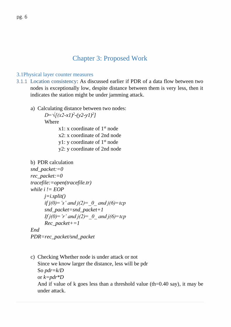
3.1Physical layer counter measures 3.1.1 Location consistency: As discussed earlier if PDR of a data flow between two
nodes is exceptionally low, despite distance between them is very less, then it
indicates the station might be under jamming attack.
a) Calculating distance between two nodes:
D=√[(x2-x1)2-(y2-y1)2]
Where
x1: x coordinate of 1st node
x2: x coordinate of 2nd node
y1: y coordinate of 1st node
y2: y coordinate of 2nd node
b) PDR calculation
snd_packet:=0
rec_packet:=0
tracefile:=open(tracefile.tr)
while i != EOP
j=i.split()
if j(0)=’s’ and j(2)=_0_ and j(6)=tcp
snd_packet=snd_packet+1
If j(0)=’r’ and j(2)=_0_ and j(6)=tcp
Rec_packet+=1
End
PDR=rec_packet/snd_packet
c) Checking Whether node is under attack or not
Since we know larger the distance, less will be pdr
So pdr=k/D
or k=pdr*D
And if value of k goes less than a threshold value (th=0.40 say), it may be
under attack.
Page 14
pg. 7
i.e
if k*100<40:
node is under attack
else:
node is not under attack
3.1.2 Signal Strength Consistency
We calculate PDR as Described earlier between source and destination node.
Then we calculate RSS according to the distance between the two nodes.
Suppose R0 is signal in node 0
And D02 is the distance between node 0 and node 2.
Then rss at node 2 with respect to node 0 will be:
rss2= R0/D02
Similarly rss3 (rss at node 3 with respect to node 0) will be:
rss3=R0/D03
so we know
pdr =K*rss
or k= pdr/rss
so If K is less than a threshold value (say th=150) then it is under attack.
i.e
if k<150:
node is under attack
else:
node is not under attack
Page 15
pg. 8
3.1 Detection of IP Spoofing
3.2.1 Calculation of sent packets
To detect an attack, we first calculate number of sent packets from each node to every
other node and set a threshold of packets.
We may want to investigate further as an attack, if for each pair of source and
destination node the number of sent packets exceeds a particular value.
Given a network traffic dataset (pcap), we analyse it packet by packet. Through dpkt
library of python we read the pcap file as an array of records in the form of [timestamp,
packets].we extract all the information like source address, destination address, TTL
value for each packets.
Calculation can be done as follows:
We need a Python dictionary: pktc{} to store number of packets for each packets.
for each packet in pcap:
stream=src + ’:’ + dst //creating key for the dictionary
if pktc.has_key(stream):
pktc [stream] = pktc[stream] + 1
else:
pktc [stream] = 1
where :
src=source IP address
dst= destination address
pktc=dictionary to store packet count value.
This code snippet checks whether the source-destination pair is already present or not
in dictionary. If it is present then increment value of packet count by one else initialise
packet count for that pair as 1.
Page 16
pg. 9
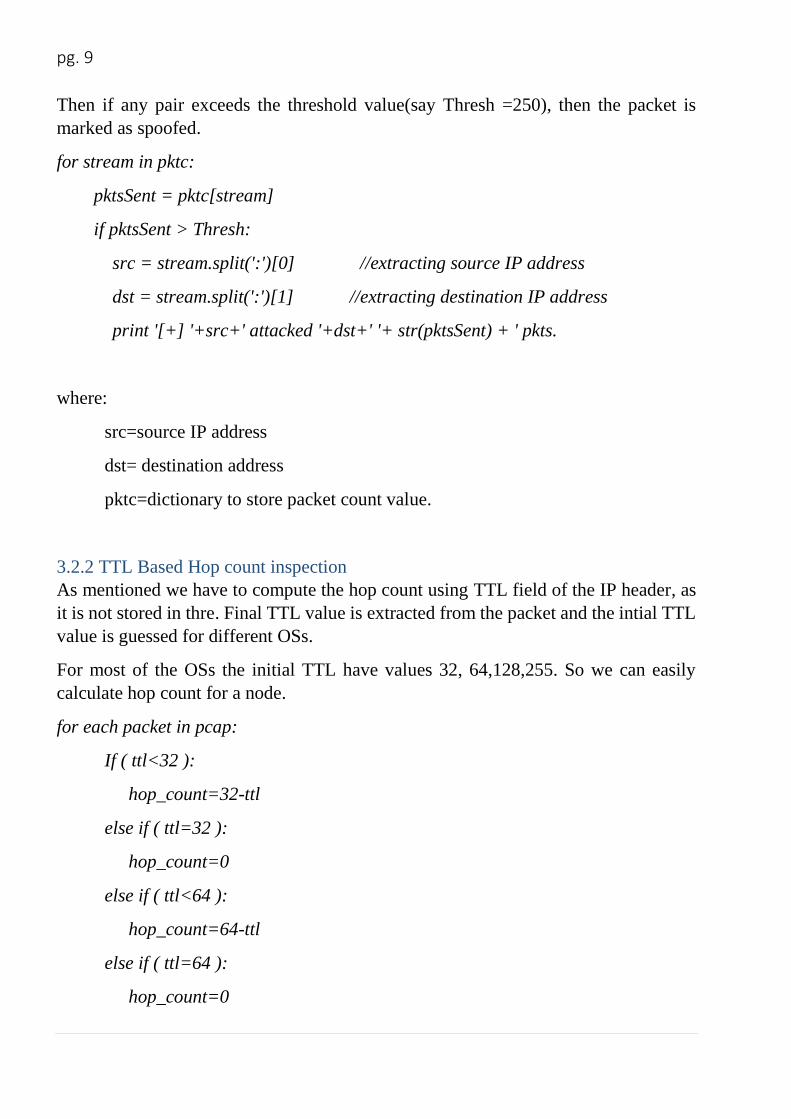
Then if any pair exceeds the threshold value(say Thresh =250), then the packet is
marked as spoofed.
for stream in pktc:
pktsSent = pktc[stream]
if pktsSent > Thresh:
src = stream.split(':')[0] //extracting source IP address
dst = stream.split(':')[1] //extracting destination IP address
print '[+] '+src+' attacked '+dst+' '+ str(pktsSent) + ' pkts.
where:
src=source IP address
dst= destination address
pktc=dictionary to store packet count value.
3.2.2 TTL Based Hop count inspection
As mentioned we have to compute the hop count using TTL field of the IP header, as
it is not stored in thre. Final TTL value is extracted from the packet and the intial TTL
value is guessed for different OSs.
For most of the OSs the initial TTL have values 32, 64,128,255. So we can easily
calculate hop count for a node.
for each packet in pcap:
If ( ttl<32 ):
hop_count=32-ttl
else if ( ttl=32 ):
hop_count=0
else if ( ttl<64 ):
hop_count=64-ttl
else if ( ttl=64 ):
hop_count=0
Page 17
pg. 10
else if ( ttl<128 ):
hop_count=128-ttl
else :
hop_count=255-ttl
Hc=hop_count
3.2.3 Inspection algorithm
The inspection algorithm to find spoofed packets is as follows:
for each packet in pcap:
extract the final TTL T and IP address S;
infer the intial TTL T0;
compute hop count Hc=T0-T;
index S to get the stored hop count Hs;
if (Hc != Hs )
packet is spoofed;
else
packet is legitimate;
3.2.4 HCF (IP2HC mapping ) table (extracting stored hop count value):
a) Clustering IP addresses based on first 24 bits:
for each packet in pcap:
extract source address S;
spl=S.split('.') //splitting each field of IP addr.
stream= spl[0] +'.' + spl[1] + '.' +spl[2] //creating 24 bit key
if pktc.has_key(stream):
HCF[stream] = min(hop count)
else:
Page 18
pg. 11
HCF[stream] = hop count of given IP address.
d) Indexing IP address to get stored IP address:
for each packet in pcap:
extract source address S;
spl=S.split('.') //splitting each field of IP addr.
key= spl[0] + '.' + spl[1] + '.' +spl[2] //creating 24 bit key
Hs = HCF[key]
Page 19
pg. 12
Chapter 4: Simulation Results
4.1 Location and Signal Strength consistency implementation results
This simulation is done in NS2.
1) Network considered for location and signal strength consistency.
Channel Type: Wireless
Radio Propagation Model: Two Ray Ground
MAC Type: 802.11
Interface Queue Type: Drop tail
Antenna Model: Omni Antenna
Routing Protocol: DSDV
Number of nodes: 8
Area(x*y):1000*1000
Figure 1. Network considered
Page 20
pg. 13
2) Calculation of distance between the nodes.
As seen from figure of the network considered, there are 8 nodes. The distance
between each pair is calculated by the distance formula mentioned in above
section.
Figure 2. Distance between each node pair
Page 21
pg. 14
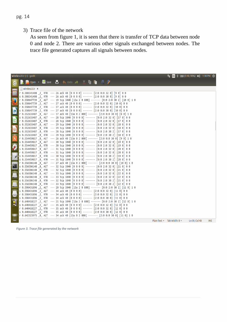
3) Trace file of the network
As seen from figure 1, it is seen that there is transfer of TCP data between node
0 and node 2. There are various other signals exchanged between nodes. The
trace file generated captures all signals between nodes.
Figure 3. Trace file generated by the network
Page 22
pg. 15
4) Results of location consistency:
The packet delivery ratio is calculated and also the distance between the nodes
0 and 2. After verification it is found out that node 2 is not under jamming attack.
Figure 4 Result of location consistency
Page 23
pg. 16
5) Received signal strength at various nodes w.r.t node 0
We find the received signal strength (RSS) of every node with respect to node 0
as mention in the earlier chapter. This RSS of node is then further used.
Figure 5.Recieved signal strength of every nodes with respect to node 0
Page 24
pg. 17
6) Result of Signal Strength consistency
The packet delivery ratio is calculated just as we did in location consistency.
And also we have calculated the RSS at node 1. Then by verification it is
found out that it is not under attack.
Figure 6. Result of signal strength consistency
Page 25
pg. 18
4.2 TTL Based Hop Count Computation
1) Calculating sent packets form each source to destination.
The count of number of packet sent from one address to another address is
stored in a python dictionary where the source- destination is used as the key
to store the packet count. If same source destination pair is encountered the
respective entry is incremented by one else a new entry is created and
initialized by 1.
Figure 7 sent packets count between two addresses
Page 26
pg. 19
2) Checking which source exceeded the threshold (150):
The sent packet counts are then checked, whether they are exceeding the
threshold value or not. Exceeding it may be a sign of an attack.
Figure 8 source addresses whose sent packet count exceed threshold value
3) TTL values for each packet with source and destination IP addresses.
In this result source IP address, destination IP address and TTL value is
extracted from pcap file.
Figure 9. Source IP address, destination IP address and TTL value extracted from the file
Page 27
pg. 20
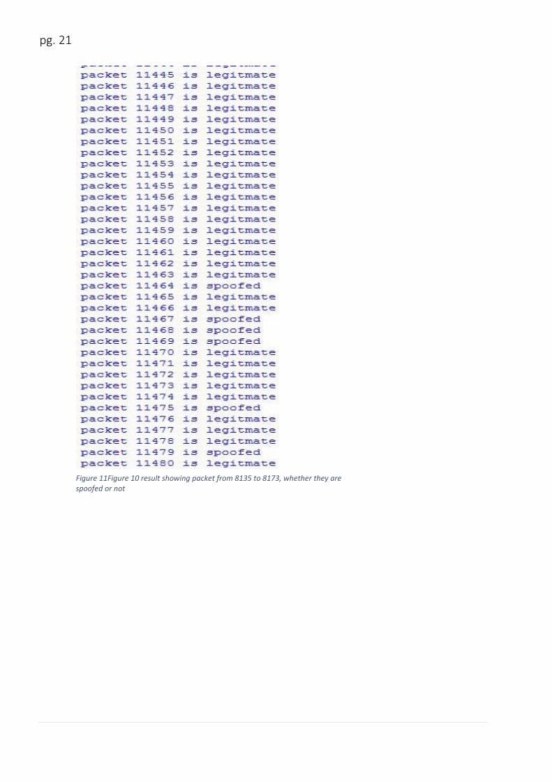
4) Result of applying inspection algorithm, whether an IP is spoofed or not:
The hop count for each packet is calculated and matched through indexing in
HCF table. As mentioned earlier if Hc!= Hs, then the packet is marked as
spoofed otherwise legitimate. In the figures below it is shown whether a packet
is spoofed or not.
Figure 10 result showing packet from 8135 to 8173, whether they are spoofed or not
Page 28
pg. 21
Figure 11Figure 10 result showing packet from 8135 to 8173, whether they are spoofed or not
Page 29
pg. 22
Chapter 5: Conclusion and future scope
In this work we presented location strength consistency, signal strength consistency
and hop count filtering method to detect DOS. Though they are not the best solution
around but they are deployable. Based on our analysis we can say that they are effective
enough to be implemented.
Further investigation may include in making HCF table more efficient by further
clustering the IP addresses. Moreover this method can further be modified to detect
and then drop the spoofed packets. We need to further refine the methods effectiveness.
These are fields of our future work.
Page 30
pg. 23
Bibliography
[1] Kemal Bicakci a,1, Bulent Tavli b,” Denial-of-Service attacks and
countermeasures in IEEE 802.11 wireless networks”, TOBB University of Economics
and Technology, Electrical and Electronics Engineering Department, Sogutozu
Caddesi No 43, 06560 Ankara, Turkey, pp. 931-941.
[2] Baber Aslam', M Hasan Islam2, Shoab A. Khan‘,” 802.11 Disassociation DoS
Attack and Its Solutions”, National University of Sciences and Technology,
Rawalpindi, Pakistan, pp. 221-230
[3] Konstantinos Pelechrinis, Marios Iliofotou and Srikanth V. Krishnamurthy,”
Denial of Service Attacks in Wireless Networks:The Case of Jammers”, IEEE
Communications Surveys & Tutorials, VOL. 13, NO. 2, second quarter 2011, pp. 245-
257.
[4] Cheng Jin, Haining Wang, Kang G. Shin,“Hop-Count Filtering: An Effective
Defense against Spoofed Traffic”, IEEE/ACM Trans. Networking, Vol. 15, No. 1,
2007, pp 40-53.