20
Portable Walk-Through Metal Detector OPERATION MANUAL
Portable Walk-Through Metal Detector
OPERATION MANUAL

OPERATION MANUALFisher Labs M-Scope™
Portable Walk-Through Metal DetectorU.S. and E.U. Patents Pending
Copyright© 2004 Fisher Research Laboratory/FRL Inc. All Rights Reserved.
TABLE OF CONTENTSIntroduction ....................... pg. 1 Features ............................. pg. 1M-Scope Expanded View ........ pg. 2 Assembly ............................ pg. 3Disassembly ........................ pg. 8Getting Started ................... pg. 10
Basic Start Up Operation ....... pg. 10Detection and Alarms ........... pg. 11 Advanced Functions .............. pg. 13Diagnostic Screens ............... pg. 16LED Testing ......................... pg. 17Tips ................................... pg. 18
FEATURES: • Modular construction for rapid deployment
• 40 Hours of battery life on a single charge
• Intuitive three-zone detection and alarm status indicators, on both entry and exit sides
• Audio alert with adjustable volume control
• Intuitive, user-friendly control panel
• Self-diagnostic
• Adaptable to virtually all environments and conditions
• 100 sensitivity settings with password protection
• Adjustable rate alarm, transit and target counters records key statistical data
• Ease-of-use facilitates “split cognition” freeing operator to monitor surroundings
The M-Scope should only be used by per-sons trained and who have a thorough un-derstanding of its operation. If the user of a M-Scope does not follow the operating manual and if the M-Scope is not set up properly, it can allow metal objects to pass through undetected.
Some objects may not be detected because of their composition, size, and location on the subject. If an undetected object passes through the M-Scope, that object may be used as a weapon in a secure area to cause injury or death.
,
Metal detectors have been associated with EMI (electromagnetic interference) that may potentially effect pacemakers and ICDs. We recommend that any patient with such a device be screened by alterna-tive methods.
1

3 RE
CEIV
ER P
ANE
LS
3 TRANSM
ITTER PANELS
BASES
CONTROL PANELTO
TE CONFIGURATION
ASS
D CONATION
2
I N T R O D U C T I O N Fisher Labs is excited to introduce the
M-Scope™ Portable Walk-Through Metal
Detector! The M-Scope™, the world’s most
versatile walk-through metal detector,
brings Fisher’s expertise, innovation, and
reputation for quality metal detection
solutions to the critical and demanding
security market.

ASSEMBLY INSTRUCTIONSBegin by selecting the most even and level surface on which to assemble your M-Scope unit. Remove the transport straps and un-stack all the components. FIG. A Place the two INTERCHANGEABLE base units on the selected ground surface. FIG. B
If your M-Scope is equipped with the leveling option proceed with step 3, if not, move to step 4. We recommend that bases with the leveler option be used on uneven surfaces. Hold the assembly level, and engage the push-button levelers by depressing each of the four lever actuators’ pushbuttons in turn. FIG.D - Depressing one of these pushbuttons releases its leveler leg so it can drop down as far as necessary to reach the fl oor below. Releasing the pushbutton locks the leg in place. Releasing the leveler legs while the control unit and bases are level to the ground allows the legs to automatically extend to the proper length necesssary to hold the M-Scope security gate assembly level. The leveler legs can make up for low spots in the ground’s surface up to two inches deep.
M-SCOPE PORTABLE WALK-THROUGH METAL DETECTOR
FIG. A FIG. B
™
3
Place control unit on top of the two bases. FIG. C - This step ensures that the bases are properly spaced, and parallel to one another. Remove the control unit and proceed to the next step.
FIG. C
FIG. D
STEP3
STEP2
STEP1
FIG. D
1 LED
ENTRANCE
FIG. E
FIG. F
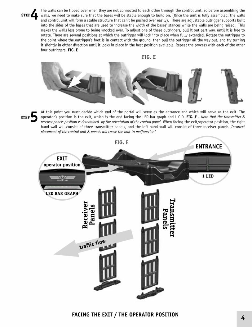
The walls can be tipped over when they are not connected to each other through the control unit, so before assembling the walls, we need to make sure that the bases will be stable enough to build on. (Once the unit is fully assembled, the walls and control unit will form a stable structure that can’t be pushed over easily). There are adjustable outrigger supports built into the sides of the bases that are used to increase the width of the bases’ stances while the walls are being raised. This makes the walls less prone to being knocked over. To adjust one of these outriggers, pull it out part way, until it is free to rotate. There are several positions at which the outrigger will lock into place when fully extended. Rotate the outrigger to the point where the outrigger’s foot is in contact with the ground, then pull the outrigger all the way out, and try turning it slightly in either direction until it locks in place in the best position available. Repeat the process with each of the other four outriggers. FIG. E
At this point you must decide which end of the portal will serve as the entrance and which will serve as the exit. The operator’s position is the exit, which is the end facing the LED bar graph and L.C.D. FIG. F - Note that the transmitter & receiver panels position is determined by the orientation of the control panel. When facing the exit/operator position, the right hand wall will consist of three transmitter panels, and the left hand wall will consist of three receiver panels. Incorrect placement of the control unit & panels will cause the unit to malfunction!
Rece
iver
Pa
nels
Transmitter
Panels
FACING THE EXIT / THE OPERATOR POSITION
STEP5
STEP4
4
ENTRANCE
LED BAR GRAPH
EXIToperator position
traffi c fl ow
TRANSMITTER PANEL/PLASTIC PLUGS
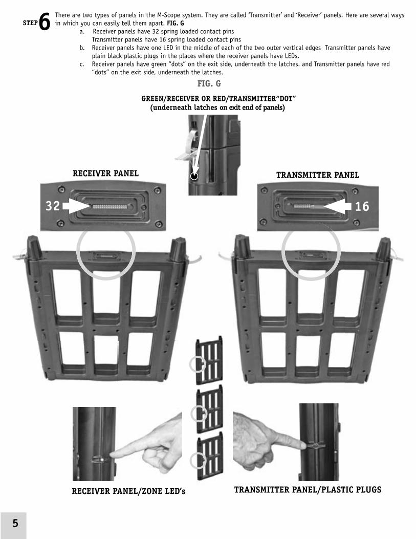
There are two types of panels in the M-Scope system. They are called ‘Transmitter’ and ‘Receiver’ panels. Here are several ways in which you can easily tell them apart. FIG. G
a. Receiver panels have 32 spring loaded contact pins Transmitter panels have 16 spring loaded contact pins b. Receiver panels have one LED in the middle of each of the two outer vertical edges Transmitter panels have
plain black plastic plugs in the places where the receiver panels have LEDs. c. Receiver panels have green “dots” on the exit side, underneath the latches. and Transmitter panels have red
“dots” on the exit side, underneath the latches.
RECEIVER PANEL TRANSMITTER PANEL
32 16
GREEN/RECEIVER OR RED/TRANSMITTER“DOT” (underneath latches on exit end of panels)
RECEIVER PANEL/ZONE LED’s
STEP6
FIG. G
5

TRANSMITTER PANEL
Being careful not to disturb the bases’ positions, connect the bases to the panels and fasten the base draw latches. The base latches may need to be adjusted from time to time. Note that on the exit side of the panels: the green “dots” will Line up on the Receiver panels and the red “dots” will Line up on the Transmitter panels. Stack the panels together by inserting a cone into the appropriate cup & fastening the panel draw latches as it is installed. Note that each panel has one “keyed” cone corresponding to one specifi c cup on another panel. FIG. H
cone
cupkeyedcone
cone
base draw latches
panel draw latches
GREEN/RECEIVER OR RED/TRANSMITTER“DOT”
STEP7
6
FIG. H

Once the walls are assembled, place the control unit on top of them, paying attention to the proper exit/entrance orientation. The control unit’s cups are keyed just like the panels’ cups are. Fasten all four of the control unit’s draw latches. FIG. I
If you are not tall enough to assemble the unit as described in steps 7 and 8, you can use a small ladder or stepstool, or you may assemble the walls with just two of the panels. Fasten the top panels to the control unit forming a structure that looks like a table FIG. J - Carefully lift this assembly onto the existing walls, and fasten the remaining latches. Avoid putting stress on the joints between the panels and the control unit by keeping the panels parallel and straight.
STEP10Push the outriggers back into the bases. FIG. K - THE UNIT’S ASSEMBLY IS COMPLETE. You may elect to plug the charger into the charger connector on either of the two bases. FIG. L - As long as the unit is powered on, one charger will charge both batteries (there is a total of two batteries, one in each base). When unit’s power is off, (as when unit is disassembled), each base will have to be connected to the charger individually, to charge both batteries. This can be done by using a standard ‘Y’ adapter. Such adapters are available from Fisher or your local distributor.
STEP9
STEP8
7
FIG. I
FIG. J
FIG. K FIG. L
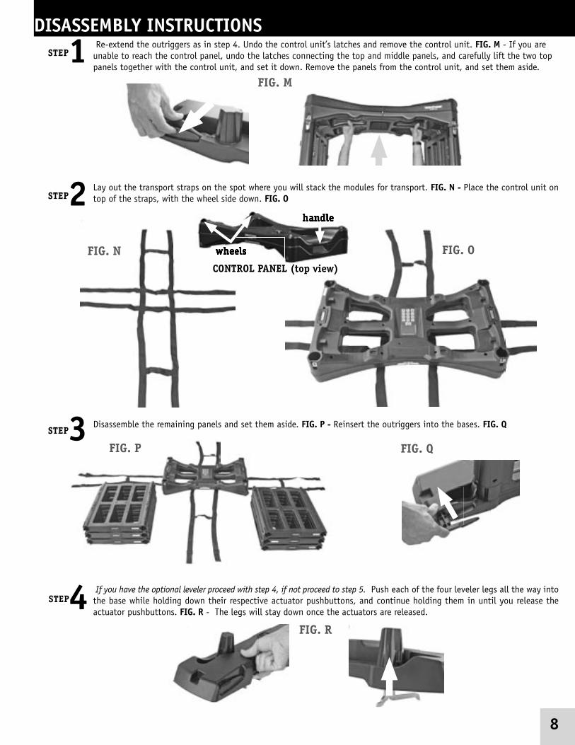
Lay out the transport straps on the spot where you will stack the modules for transport. FIG. N - Place the control unit on top of the straps, with the wheel side down. FIG. O
Disassemble the remaining panels and set them aside. FIG. P - Reinsert the outriggers into the bases. FIG. Q
DISASSEMBLY INSTRUCTIONS Re-extend the outriggers as in step 4. Undo the control unit’s latches and remove the control unit. FIG. M - If you are unable to reach the control panel, undo the latches connecting the top and middle panels, and carefully lift the two top panels together with the control unit, and set it down. Remove the panels from the control unit, and set them aside.
handle
wheels
handle
wheelswheels
CONTROL PANEL (top view)
8
STEP1
STEP2
STEP3
FIG. M
FIG. N FIG. O
FIG. P FIG. Q
If you have the optional leveler proceed with step 4, if not proceed to step 5. Push each of the four leveler legs all the way into the base while holding down their respective actuator pushbuttons, and continue holding them in until you release the actuator pushbuttons. FIG. R - The legs will stay down once the actuators are released.
STEP4FIG. R

Stack the panels on top of the bases such that the cones are nearest to the wheel ends of the control unit. FIG. U - Make sure that their stacking features are fi rmly engaged such that the panels, bases, and control unit all nest together snugly. FIG. V
Fasten the straps securely. Stand it up on its wheel end. FIG. W - THE M-SCOPE IS READY FOR TRANSPORT AND STORAGE.Exercise caution when standing the unit up on its end. The sudden shift in weight may cause the unit to rock away from you.
If your car is too small to accommodate the entire unit in one block, simply remove the straps and load the components wherever there is room for them. The entire M-Scope can be loaded into the back seat of a small car. You may wish to un-stack the components and load them individually if the entire unit is too heavy for you to lift by yourself. The M-Scope weighs about 90lbs, which is very light for a security portal, but too heavy for most people to safely lift, unaided. 9
STEP7
STEP8
All of the components have a series of projections and indentations that are designed to nest within each other when the components are stacked together for transport. These are called the ‘Stacking Features’. They keep the components from sliding around within the stack when they are strapped together for storage or transport. Make sure the bases are positioned so their stacking features nest on the control unit securely. FIG. T
STEP6
FIG. T
FIG. U FIG. V
FIG. W
Turn the bases upside down and place them on the control unit. FIG. SSTEP5 FIG. S

GETTING STARTED
DIGIT EXPANDED ABBREVIATION ABBREVIATION0 Shut down, [On/Off], Exit On/ Off1 Volume menu VOL2 Sensitivity menu SENS3 Contrast menu CON4 Counter menu CNT5 Rate Alarm menu RATE6 Factory Presets FPSET7 User Presets 1 PRO18 User presets 2 PRO29 User presets 3 PRO3
All of the M-Scope’s commands are entered through the twelve-button keypad on the control unit. The two up/down arrows are essentially single function buttons. The other ten buttons labeled 0 through 9 are all multi-function buttons. Multi-function buttons are annotated with corresponding abbreviations. The following is a list of the complete expressions for those abbreviations.
BASIC START UP OPERATION
KEYPADCONTROL PANEL (bottom view)
Most often, the operator will simply turn the unit on, and use the settings already stored in memory. For fi rst time use, the unit will be set at Factory Preset settings which prepare the unit for basic, standardized operating conditions. Note that these settings may not be appropriate for an operators unique environment and specifi c security requirements. A thorough understanding of the M-Scopes operation, and most notably, sensitivity settings, is required for effective, accurate metal detection.
Turn the unit on by momentarily pushing the on/off [numeral 0] button on the control panel keypad. The unit will power up and begin a self diagnostic check.
The LCD will display the Title Screen and the battery voltage during the self-check. The unit will check its seven LED lights on the LED bar graph one at a time, starting with the fi rst (lowest) green one, through the yellow ones all the way up to the last (highest) red one, then back down to the fi rst green one again. After this check is completed, the bar graph display will enter its normal mode, continuously indicating the strength of the metal detection signal it is measuring. Some of this signal may be a representation of various types of electromagnetic noise interference (RFI/EMI) in the area.
During the self check, the multi-colored, triple zone, alarm indicator LEDs as well as the two multi-colored ready indicator LEDs, will glow red momentarily. Once the self check ends satisfactorily, they will all change to green.
When the M-Scope passes its self check successfully, the unit becomes ready to detect targets. The user selections will be described elsewhere in this document under the Advanced Functions heading.
10
STEP1STEP2
The M-Scope should only be used by per-sons trained and who have a thorough un-derstanding of its operation. If the user of a M-Scope does not follow the operating manual and if the M-Scope is not set up properly it can allow metal objects to pass through undetected.
Some objects may not be detected because of their composition, size and location on the subject. If an undetected object passes through the M-Scope that object may be used as a weapon in a secure area to cause injury or death.

DETECTION AND ALARMSSensing Subjects in the M-ScopeThe metal detection alarm decision-making process begins the moment a subject breaks any one of the six invisible beams of infrared light inside the M-Scope’s passageway; typically one of the three beams at the portal’s entrance. Note that the LED bar graph continuously displays the received signal’s strength, but the alarm will not be triggered until something enters the security gate and passes through one of the sensors’ light paths.
Going too FastOnce the M-Scope detects something in the passageway, it begins measuring the elapsed time between when the fi rst beam is crossed upon entering the passageway, and when the second beam is crossed upon exiting the passageway. The measurement of the time it takes for a subject to pass through the gate tells the system how fast the subject was going through the passageway. If the subject exceeds the M-Scope’s selected speed limit; the LCD displays “Speed Violation!”, the audio alert sounds, the zone lights fl ash red, and the bar graph and ready LEDs fl ash several times. These events get logged in the system’s internal counters.
Going too SlowIf any of the six light beams remains blocked for more than a few seconds, the unit goes into the Photo Detector Blocked alarm mode, featuring red zone and ready indicator LEDs, sounding audio alert, and a special LCD screen, displaying the words “Photo Diode Blocked!” along with a graphic display consisting of six circles arranged as three pairs, corresponding to the three pairs of infrared LED and Photodiode sensors. Each individual circle’s interior will either be blank, partially fi lled in, or entirely fi lled in, indicating whether the corresponding Photo Detector sensor channel is getting zero signal, a partial signal, or a full strength signal. This feature can be very useful when troubleshooting the unit.
The LED bar graph also indicates which of the six ‘electric eye’ Photo Detector channels are working properly and which are not, by fl ashing:
• LED1 if the top light beam on the exit side is blocked• LED2 fl ashes when the middle beam on the exit side is blocked• LED3 fl ashes if the bottom beam on the exit side is blocked• LEDs 5,6,7 correspond to the top, middle, and bottom light sensor channels on the entrance
side. These LEDs glow steadily (without fl ashing) to indicate good Photo Detector channels in this alarm mode.
Finding Metal Targets Without Speed ViolationsWhile the portal is occupied, the zone lights stay green, the status light glows yellow, and the ready lights glow red. The LED bar graph refl ects the received signal strength actively. If none of the three zones received a target signal strong enough to exceed the current alarm threshold, the zone and ready lights will turn green again when the subject comes out. This event, like all the other events, will be logged automatically, and the M-Scope will be ready to scan the next subject.
ONE DIODE BLOCKED
ALL DIODES BLOCKED
11

12
Zone IndicationThe M-Scope has three zones. If one or more of the zones detect target signals strong enough to exceed the alarm threshold, the audio alert will sound, and the LED bar graph will flash several times. The zone indicator light corresponding to the zone where the strongest signal was received will glow red. The zone indicator light for any other zone that detected a signal strong enough to exceed the alarm threshold will repeatedly change its color between red and green at a rate that will tend to make the indicator light appear yellow. The zone indicator light for any zone that did not receive a threshold crossing signal, will continue to glow green. No more than one zone indicator can glow red at a time. No more than two can glow yellow (alternating red and green) at a time. Any combination of green zone indicators is possible.
After finding target(s), the audio alert will continue to beep and the alarm indicator lights will continue to flash for about five seconds before the M-Scope indicates readiness to accept the next subject with a steady green ready light.
Key Stuck AlarmWhen any key is held down for more than twenty seconds, the bar graph LEDs go dark, the zone and ready indicators turn red, and the LCD screen shows the words “Key Is Stuck!”. It also shows a representation of the keypad itself with the properly functioning keys shown with dark numerals on light backgrounds, whereas the stuck key shows light numerals on dark background.
Shut Down SequenceTo shut down the M-Scope security gate, press the shut down key [numeral 0]. The LCD will show the words “SHUTDOWN STARTED.” You must press the numeral 1 key within five seconds of the shutdown screen’s appearance to complete the shut down process, or else the system will return to the normal operating mode. The LED bar graph will illuminate singly, in descending order, marking the stages of the shutdown process.
The M-Scope has an automatic self-shutdown safeguard that will prevent complete battery drainage. If the battery level is too low, the unit will automatically shut down and will remain off until the battery is sufficiently charged, or the battery charger is plugged in.
Battery Low AlarmThe M-Scope is powered by sealed lead acid batteries similar to those used in automobiles. Keeping a load on such batteries when their voltages are too low will eventually destroy them, so the M-Scope design prevents that from happening. When the battery voltage gets too low, [i.e. < 11 Volts ], the LCD announces “Low Battery Alarm” along with the batteries’ voltage level and the time remaining before the unit shuts itself down. No matter how completely discharged the batteries are, the M-Scope will work properly as long as the battery charger is connected.

13
Sensitivity MenuThe sensitivity setting determines the unit’s ability to detect metal objects. The higher the sensitivity, the more responsive it will be to relatively small metal concentrations. To adjust the sensitivity, press the sensitivity key (numeral 2). Use the up/down arrows to adjust the sensitivity setting to any number from 1 to 99. Sensitivity settings should be selected and adjusted based on your facilities particular security needs and operating environment. The M-Scope will retain your sensitivity settings in memory when you turn the power off.
Zone SettingsIt is possible to adjust the individual zone sensitivities to fine tune the performance of the M-Scope. Once in the sensitivity menu, press any key other than the Up, Down or 0 button. This will display the Zone select screen. The three bar graphs and numerical reading represent the settings for the TOP (top bar graph), MIDDLE (middle bar graph), and Bottom (bottom bar graph) zones. These settings range from 0.00 (which corresponds to a zone being completely ignored) to a value of 2.00 (which corresponds to a zone having twice the sensitivity as set by the Sensitivity Menu). A value of 1.00 corresponds to a zone having an equal setting as the sensitivity menu. Pressing numerals adjusts the settings for the zones. Pressing numeral 1, decreases the sensitivity for the top zone. Pressing numeral 2, resets the top zone to a value of 1.00. Pressing numeral 3, increases the sensitivity to only the top zone. In similar fashion, buttons 4,5 and 6 adjust the zone settings for the middle zone. Buttons 7,8 and 9 adjust the settings for the bottom zone. Pressing the Up, Down or 0 numeral, returns to the Sensitivity Menu.
Contrast Menu To adjust the LCD display contract press the contract key (numeral 3) when the M-Scope is in normal operating mode. Use the up/down arrows to adjust the contract. Contrast settings are automatically saved into memory, as well are the user adjusted settings. Press numeral 0 (of wait ten seconds) to exit the contract menu.
ADVANCED FUNCTIONSYou may exit any of these menu modes by pressing the exit key [numeral 0], or by waiting for the ten second keyboard timeout, after which the M-Scope will automatically revert to normal operating mode. Hold the up/down arrow keys for more than one second for rapid increment or decrement.
Volume MenuThe volume and beep rate are adjustable. To adjust the volume, press the volume key (numeral 1) when the M-Scope is in normal operating mode. The unit will start beeping on its own. Use the up/down arrow keys to adjust the volume.
• To adjust the beep rate, press any button from numeral 1 to 6 while in the volume menu. Below is a chart of the beep rate:
Numeral 1 key Steady tone All bar graph lights ONNumeral 2 key 1 Beep/Second Red LED 7 flashesNumeral 3 key 2 Beeps/Second Yellow LED 6 flashesNumeral 4 key 4 Beeps/Second Yellow LED 5 flashesNumeral 5 key 8 Beeps/Second Green LED 4 flashesNumeral 6 key 16 Beeps/Second Green LED 3 flashes
Press numeral 0 [or wait ten seconds]to exit the volume menu. The M-Scope will retain your settings in memory when you turn the power off.

14
Counter Menu / StatisticsTo view the counters’ contents, press the counter key [numeral 4] while the M-Scope is in normal operating mode. The LCD will display the four counters’ names [people counter, metal target counter, speed violations counter, access alarm counter] and display the values stored in them. To reset the counters, press the numeral 1 key. Press numeral 0 [or wait ten seconds] to exit the counter menu.
Rate Alarm MenuTo access the rate alarm menu, press the rate key [numeral 5] while the M-Scope is in normal operating mode. The LCD will show the rate alarm setting. There are six possible settings including the disable rate alarm setting [i.e. 0.2m/S, 0.5m/S, 1.0m/S, 1.5m/S, 2.0m/S, Disabled] . All rates are expressed in meters per second. Use the Up/Down arrows to adjust the rate alarm setting. . Press numeral 0 [or wait ten seconds] to exit the rate alarm menu. If the rate alarm is not set to DISABLED, a subject taking too long (more than 7.5 seconds) to exit the M-Scope will also cause a speed violation.
Access Menus / Password ProtectionAccess to adjustable parameters such as sensitivity and rate alarm settings, and to the statistics counters, may be password protected using the features found on the Access menu. Pressing the Down arrow key while the M-Scope is in normal mode opens the access menu. If the Access feature is enabled, meaning the system is currently under password protection, the LCD screen will prompt you to enter the current access code.
• System will respond to an incorrect access code entry by displaying code mismatch.
• After each unsuccessful attempt, the system will display Access Denied and the event will be logged in the statistics counter under the Access alarm counter heading.
There are locations for storing four different access codes, for use by different individuals.Location 1 is the Master 1 access code location. Whenever the M-Scope is password protected by Access enable, a Master level password is needed to access: 1. Change the sensitivity level2. Access the counter menu3. Change the rate alarm setting4. Edit the access codes5. Change/Access Presets
User level access codes allow changes to be made to the volume and contrast. No access code is needed to turn on or off the unit. When you open the access menu with a Master level code, you can choose between access enabled and access disabled, by pressing the numeral 5 key.

15
Editing the access menu is the way to change access codes, and enable or disable the access protection feature.
To change an access code, open the Edit access menu, and then press the numeral key corresponding to the code location you wish to change. For example, press numeral 1 to change the Master 1 access code. Similarly, press the numeral 2 key to change the User 2 access code, etc. This will open the Reset access code screen.
Here is the User 2-reset access code screen. Enter the new code. The code can be of any length from one through ten digits long.If no key is pressed within four seconds, the system will revert back to the Edit Access screen. Because there is no Enter key, and the code password length is not fixed, you must wait for the four-second timeout after you finish entering your new code.
Four seconds after entering the new User 2 code, the system will switch to the Re-enter access code menu, and prompt you to verify the new code by re-entering it.
If the two entries do not match, the system will display Code Mismatch and return to the Reset access code menu after a four second pause.
After the new user code has been successfully entered and verified, the system will open the Code saved menu. This feature allows the status of the newly stored access code’s user to be assigned either User or Master status. Each time the numeral 1 key is pressed, the code saved menu screen will alternate between displaying User and Master. User # 1 always has Master’s status. Press the Numeral 0 key to return to the Edit access menu. Press numeral 0 [or wait ten seconds] to exit the Access menus.
Pre SetsThe M-Scope’s ideal group of settings may change with different users’ individual preferences, or in different security applications. The M-Scope can store three separate groups of settings under the headings of User Presets 1, 2 and 3. These correspond to numeral keys 7,8 and 9 respectively. A fourth group of settings, called the Factory Pre-sets, corresponds to the numeral 6 key. To configure the M-Scope to use any of these four preset groups, simply press the corresponding numeral key when the M-Scope is in normal operating mode. For example, pressing the numeral 8 key will set the M-Scope to the configuration stored in User pre set 2. To assign a group of settings to one of the User pre sets, adjust the all of the M-Scope’s variables as discussed in the preceding instructions, and then press and hold the corresponding numeral key for at least one second to store the settings. This is similar to the way most car radio pre- ets are stored. Note: the Factory pre sets cannot be changed. If the M-Scope is password protected (Access enabled mode), the system will prompt the operator to enter in their password, or Access code. Changing the values in any of the three User pre sets while the unit is in the Access enabled mode, requires a Master level access code.
16
Please contact the Fisher factory or your Fisher Sales Representative, or Distributor if you have not had technical training on accessing the diagnostic screens!
Diagnostics Screens
The M-Scope has a Diagnostic Mode that can be used to check the performance of its six Photo Detector channels, and of its three separate metal detector zones. It is also useful for exercising all of the system’s various LEDs. This mode was not designed for M-Scope operators’ use. Misusing it can’t damage anything, so its operation is described below.
To enter the diagnostic mode, begin with the power to the M-Scope turned off. Turn the power on, and quickly press the down arrow key, then the up arrow key, then wait for the unit to complete its LED sequencing self test pattern. Each of these arrow key presses must be done within two seconds of powering on.
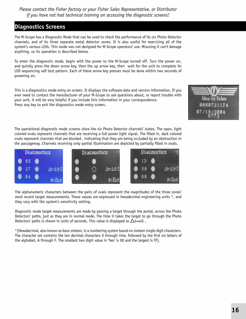
This is a diagnostics mode entry on screen. It displays the software date and version information. If you ever need to contact the manufacturer of your M-Scope to ask questions about, or report trouble with your unit, it will be very helpful if you include this information in your correspondence.Press any key to exit the diagnostics mode entry screen.
The operational diagnostic mode screens show the six Photo Detector channels’ states. The open, light colored ovals represent channels that are receiving a full power light signal. The filled in, dark colored ovals represent channels that are blocked , indicating that they are being occluded by an obstruction in the passageway. Channels receiving only partial illumination are depicted by partially filled in ovals.
The alphanumeric characters between the pairs of ovals represent the magnitudes of the three zones’ most recent target measurements. These values are expressed in hexadecimal engineering units *, and they vary with the system’s sensitivity setting.
Diagnostic mode target measurements are made by passing a target through the portal, across the Photo Detectors’ paths, just as they are in normal mode. The time it takes the target to go through the Photo Detectors’ paths is shown in units of seconds. This value is displayed as t=xxS .
*{Hexadecimal, also known as base sixteen, is a numbering system based on sixteen single digit characters. The character set contains the ten decimal characters 0 through nine, followed by the first six letters of the alphabet, A through F. The smallest two digit value in ‘hex’ is 00 and the largest is FF}.

LED TestingThe LEDs can be controlled manually while in the diagnostics mode by pressing the different numeral keys. Duration is approximately 4.5 seconds, then returning to diagnostic mode. The ready light will go green and the LED bar graph displays the signal strength.
Numeral 1 key Bar graph LED 1 on GREEN
All Zone [“RX” ] Lights glow GREEN Status Light OFF Ready [go/stop] Light
OFF
Numeral 2 key Bar graph LED 2 on GREEN
Top Zone Light GREEN
Middle Zone Light GREEN
Bottom Zone Light YELLOW
Status Light OFF Ready Light OFF
Numeral 3 key Bar graph LED 3 on GREEN
Top Zone Light GREEN
Middle Zone Light GREEN
Bottom Zone Light RED
Status Light OFF Ready Light OFF
Numeral 4 key Bar graph LED 4 on GREEN
Top Zone Light GREEN
Middle Zone Light GREEN
Bottom Zone Light GREEN
Status Light OFFReady Light OFF
Numeral 5 key Bar graph LED 5 on YELLOW
Top Zone Light
GREEN
Middle Zone Light YELLOW
Bottom Zone Light GREEN
Status Light OFF Ready Light OFF
Numeral 6 key Bar graph LED 6 on YELLOW
Top Zone Light GREEN
Middle Zone Light RED
Bottom Zone Light GREEN
Status Light OFFReady Light OFF
Numeral 7 key Bar graph LED 7 on RED
Top Zone Light GREEN
Middle Zone Light GREEN
Bottom Zone Light GREEN
Status Light OFF Ready Light OFF
Numeral 8 key Bar graph LEDs all OFF
Top Zone Light YELLOW
Middle Zone Light GREEN
Bottom Zone Light GREEN
Status Light GREEN Ready Light GREEN
Numeral 9 key Bar graph LEDs all OFF
Top Zone Light RED
Middle Zone Light GREEN
Bottom Zone Light GREEN
Status Light YELLOW
Ready Light YELLOW
Down arrow key Bar graph LEDs all ON
Top Zone Light RED
Middle Zone Light RED
Bottom Zone Light RED
Status Light RED Ready Light RED
Up arrow key Bar graph LEDs all OFF
Zone Lights all GREEN Status Light OFF
Ready Light OFF
Toggles 50/60Hz selection
Numeral 0 key Under system control Under system control Under system control
Under system control
Returns to normal operating mode
17

Tips1. Unit comes on and then cycles off.
a. Check the battery voltage and if below 10.9 volts, recharge the batteries completely or hook up the charging unit. The voltage must be above the 10.9 range or the unit will not come on. See Fig. L
2. Unit tries to come on but won’t power up.a. Check the position of all the transmit and receive panels and make sure they are
placed properly, and that the top is put on correctly. There are red and green dots under the latches that are used to help with the correct placement of the panels. See Fig. G
3. Unit comes on but has no display on screen (blue screen).a. Press the number 3 key on the control panel and then use the up arrow until the
screen contrast returns the desired level. orb. Press the factory preset key #6 or any of the user preset keys #7, 8, or 9.
4. Unit comes on but has a blocked photo diode.a. Disassemble the unit and reassemble it placing the receive panels in a different
order. Make sure to check for proper placement of the bases. If the unit still shows a blocked diode but in another location the panel will need to be replaced.
b. Make sure that the unit is placed on level ground so that the panels are parallel with each other. We recommend that bases with the leveler option be used on uneven surfaces.
5. Unit is plugged into the charger but the voltage isn’t going up.a. Make sure the AC plug is plugged in to a live outlet, and that the charger output
plug is pushed all the way in to the unit and making good contact. See Fig. L
6. To switch unit to operate at 50/60 Hz mode. a. In diagnostic mode, press the up button which will allow you to toggle between
50/60 Hz. When operating in countries with 60 Hz AC power, the 60 Hz mode should be selected. Conversely, when operating in countries with 50 Hz AC power, the 50 Hz mode should be selected. 50 Hz will not operate correctly within a 60 Hz environment and vice versa.
7. Fisher recommends that all M-Scope units intended for outdoor useage be used with our Weather Protective Package option. This option includes a pop-up shelter that shields the M-Scope from direct sunlight (UV rays), and from rainfall. The “Weather Protected” option also includes a mat to keep the bases from getting excessively dirty.
8. Please see details on your warranty card if service becomes necessary or contact the Fisher factory.
18
DIMENSIONS• 88” x 43.5” x 23.75”
PORTABLE DIMENSIONS• 37” x 23” x 26”
WEIGHT• 90 lbs.
SPECIFICATIONS• Temp -20 C to +60 C (-4 F to +140 F)• Relative Humidity 95% non condensing
WARRANTY• 24 months parts and labor

for inquiries from Western Europe, & South America contact:
Export Department28o State Street, Suite 202 North Haven, CT 06473 USA,
T 203.230.4130 F 203.248.8093 email: [email protected]
SECURITY SOLUTIONS
FRL#8730021
Fisher Research Laboratory200 W. Willmott Rd., Los Banos, CA 93635
tel 209-826-3292 fax 209.826.0416 [email protected] www.fisherlab.com