DETERMINATION OF BURST PRESSURE OF DEFECTIVE STEEL PIPES USING FINITE ELEMENT ANALYSIS MOHAMAD ZULFADLI BIN MOHAMAD RANI Thesis submitted in fulfilment of the requirements for the award of the degree of Bachelor of Mechanical Engineering Faculty of Mechanical Engineering UNIVERSITI MALAYSIA PAHANG JUNE 2012
Transcript
DETERMINATION OF BURST PRESSURE OF DEFECTIVE STEEL PIPES
USING FINITE ELEMENT ANALYSIS
MOHAMAD ZULFADLI BIN MOHAMAD RANI
Thesis submitted in fulfilment of the requirements
for the award of the degree of
Bachelor of Mechanical Engineering
Faculty of Mechanical Engineering
UNIVERSITI MALAYSIA PAHANG
JUNE 2012
vii
ABSTRACT
This thesis deals with assessment of defective API 5L X65 steel pipes which are widely
used in product transportation in oil and gas industry. The objective of the thesis is to
determine the burst pressure of defective API X65 steel pipes under the effect of gouge
length for different pipe diameter. The thesis describes the finite element analysis
techniques to predict the true fracture and identify the critical locations of the structures
(pipe). One-quarter three-dimensional solid modelling of steel pipe was developed using
the MSC Patran 2008r1 that act as a pre-processor. The finite element analysis was then
performed using MSC Marc. The finite element model of the pipe was analyzed using
the non-linear isotropic elasto-plastic material that obeys the incremental of plastic
theory. The values of principal stresses and strains acted on the critical location of gouge
defect had been obtained by MSC Patran as a post-processor. The values were used to
determine the true fracture strain which is known to be exponentially dependent to the
stress triaxiality. Finally, burst pressure was determined as the true fracture strain
exceeds the value of equivalent strain at that instant point. Based on the results, it is
observed that the analysis using SMCS model yields more conservative burst pressure
prediction. The obtained results indicate that the shorter gouge length would gives
higher burst pressure which means, higher pressure needed as the pipe to experience
failure at the gouge defect area. Result shows that the burst pressure decreases with
increment of pipe diameter. The results concluded that the shorter gouge length and
smaller pipe diameter conditions give the highest pressure value of pipe burst.
Therefore, the defect characteristic is the promising criteria to increase the fitness of
service of the pipe.
viii
ABSTRAK
Tesis ini berkaitan dengan penilaian kecacatan bagi paip keluli API 5L X65 yang
digunakan secara meluas untuk pengangkutan produk dalam industri minyak dan gas.
Objektif tesis ini adalah untuk menentukan tekanan maksimum yang boleh ditanggung
oleh paip keluli API X65 yang mengandungi kecacatan (gouge) dengan diameter paip
yang berbeza. Tesis menerangkan teknik-teknik analisis unsur terhingga untuk
meramalkan patah sebenar dan mengenal pasti lokasi kritikal struktur (paip). Satu-
perempat tiga-dimensi pemodelan paip keluli telah dibangunkan dengan menggunakan
MSC Patran 2008r1 yang bertindak sebagai pra-pemproses. Analisis unsur terhingga
telah dilakukan menggunakan penyelesai MSC Marc. Model unsur terhingga paip telah
dianalisis dengan menggunakan bahan yang mempunyai ciri-ciri isotropi elastic-plastik
yang mengikut kepada peningkatan teori plastik. Nilai-nilai tegasan dan terikan utama
bertindak di lokasi kritikal kecacatan telah diperolehi oleh MSC Patran yang digunakan
sebagai pasca-pemproses. Nilai-nilai tersebut telah digunakan untuk menentukan terikan
patah sebenar yang juga eksponen bergantung kepada tekanan tiga paksi. Akhirnya,
tekanan pecah ditentukan sebagai terikan patah benar melebihi nilai terikan pada titik
tersebut. Berdasarkan keputusan, ia diperhatikan bahawa analisis yang menggunakan
model SMCS menghasilkan ramalan tekanan pecah yang lebih konservatif. Keputusan
yang diperolehi menunjukkan bahawa kecacatan (gouge) yang lebih pendek akan
memberikan tekanan pecah yang lebih tinggi. Keputusan menunjukkan bahawa tekanan
pecah berkurangan dengan pembesaran saiz paip. Keputusan yang diperolehi
menyimpulkan bahawa kecacatan yang pendek dan diameter paip yang lebih kecil
memberikan nilai tekanan tertinggi sebelum paip pecah. Oleh itu, ciri-ciri kecacatan
adalah kriteria yang menjanjikan untuk keselamatan paip yang boleh digunakan.
ix
TABLE OF CONTENTS
Page
EXAMINER’S APPROVAL ii
SUPERVISOR’S DECLARATION iii
STUDENT’S DECLARATION iv
DEDICATION v
ACKNOWLEDGEMENTS vi
ABSTRACT vii
ABSTRAK viii
TABLE OF CONTENTS ix
LIST OF TABLES xii
LIST OF FIGURES xiii
LIST OF FORMULA xv
LIST OF SYMBOLS xvi
LIST OF ABBREVIATIONS xvii
CHAPTER 1 INTRODUCTION
1.1 Project Background 1
1.3 Objectives 2
1.3 Scope of Project 2
1.4 Problem Statements 2
CHAPTER 2 LITERATURE REVIEW
2.1 Introduction 4
2.2 History 5
2.3 API 5L X65 5
2.4 Type of Defects on Steel Pipes 6
2.4.1 Gouge 7
2.4.2 Dent 7
2.4.3 Corrosion 7
1 × ENTER (1.5 line spacing)
x
2.5 Stress Acted on Pipe 8
2.5.1 Hoop Stress 9
2.5.2 Radial Stress 11
2.5.3 Axial Stress 11
2.5.4 Burst Pressure of Pipe 12
2.6 Theory 12
2.6.1 Stress-Strain Curve 13
2.6.2 Yield Stress 14
2.6.3 Maximum-Shearing-Stress vs. Maximum-Distortion-Energy
Theory
14
2.7 Stress-Modified Critical Strain 17
2.7.1 Stress Triaxiality Variations 17
2.7.2 Stress-Modified Fracture Strain 18
CHAPTER 3 METHODOLOGY
3.1 Introduction 19
3.2 Project Flowchart 19
3.3 Type of Project 21
3.4 Scope of Work 21
3.5 Pipe Modelling 22
3.5.1 Outline of the Pipe 23
3.5.2 Pipe Modelling 24
3.5.3 FE Meshing on Pipe Model 26
3.5.4 Boundary Conditions and Internal Pressure 27
3.5.5Material Properties 28
3.6 Simulation Procedures 31
3.6.1Analysis of the Pipe Model 32
3.6.2 Determining Burst Pressure 33
3.7 Scope of Output 34
3.7.1 Parametric Studies 34
3.7.2 Gouge defects 35
3.7.3 API RP FFS 579 37
xi
CHAPTER 4 RESULTS AND DISCUSSION
4.1 Introduction 39
4.2 508 mm Outer Diameter Burst Result 40
4.3 762 mm Outer Diameter Burst Result 42
4.4 1016 mm Outer Diameter Burst Result 43
4.5 Discussion 44
4.5.1 Summary of Burst Result 44
4.5.2 Burst Pressure vs. Radial Displacement 47
4.6 Comparisons of Level 1 Assessment API 579 RP FFS 49
CHAPTER 5 CONCLUSION AND RECOMMENDATIONS
5.1 Conclusion 53
5.2 Recommendation 54
REFERENCES 55
APPENDICES
A Gantt Chart 57
xii
LIST OF TABLES
Table No. Title Page
2.1 Chemical composition of the API X65 steel 5
2.2 Mechanical tensile properties at room temperature of the API
X65 steel
6
3.1 Dimensions of the full-scale pipe model with gouge defect 25
3.2 Variation of pipe diameter and gouge length for parametric
study
35
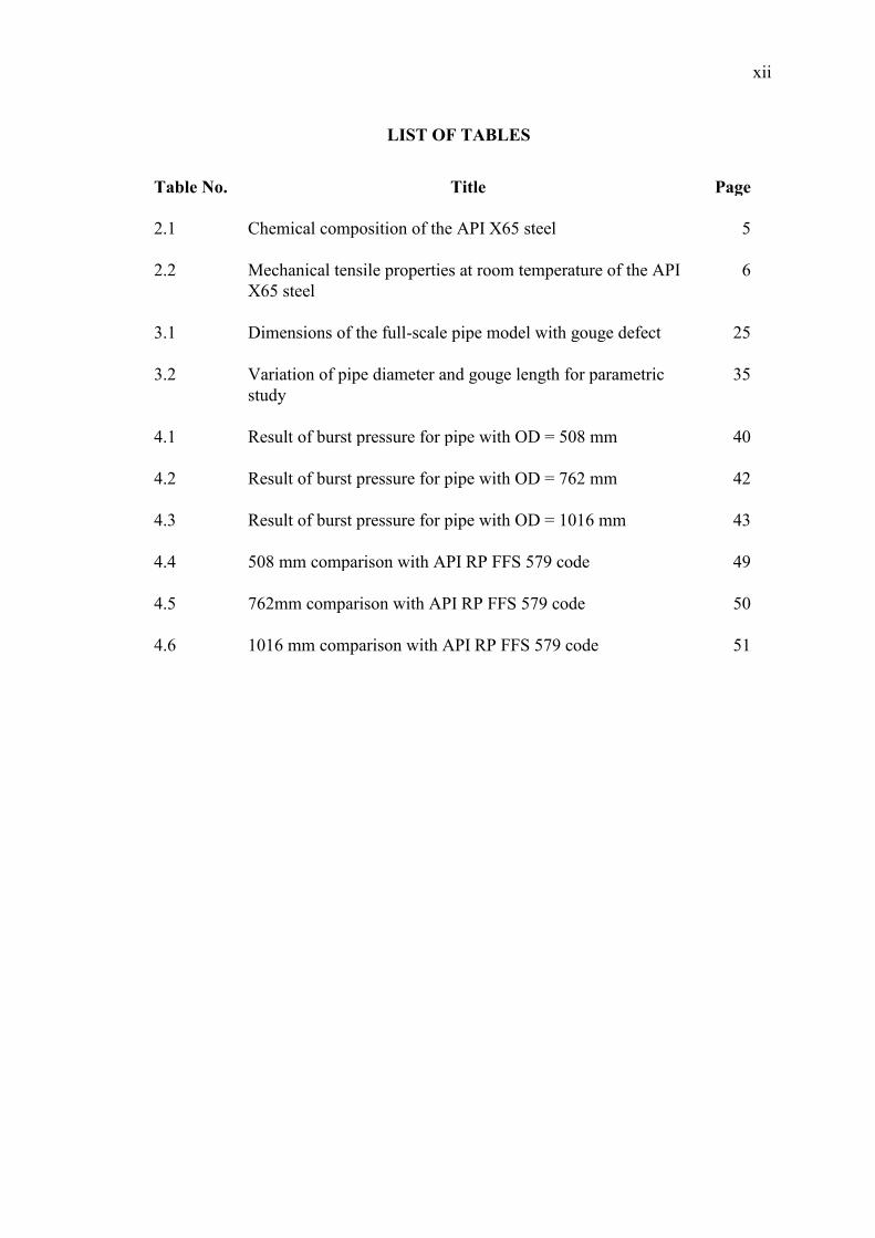
4.1 Result of burst pressure for pipe with OD = 508 mm 40
4.2 Result of burst pressure for pipe with OD = 762 mm 42
4.3 Result of burst pressure for pipe with OD = 1016 mm 43
4.4 508 mm comparison with API RP FFS 579 code 49
4.5 762mm comparison with API RP FFS 579 code 50
4.6 1016 mm comparison with API RP FFS 579 code 51
xiii
LIST OF FIGURES
Figure No. Title Page
2.1 Gouged steel pipes 6
2.2 Direction of hoop stress and longitudinal stress 9
2.3 Ratio of pipe radius to pipe thickness 10
2.4 Hoop stress acted on steel pipes 10
2.5 Longitudinal stress acted on steel pipes 11
2.6 Stress-strain curve of a ductile material 14
2.7 Tresca diagram 15
2.8 Distortion energy diagram 16
2.9 Principle stress acted at a point 17
3.1 Project flowchart 20
3.2 Illustration of defective pipe 22
3.3 Solver options 23
3.4 Geometry dimension options 23
3.5 Initial pipe surface 24
3.6 Symmetrical pipe model 25
3.7 Detail meshing on the pipe 26
3.8 Detail meshing on gouge defect 27
3.9 Boundary conditions and internal pressure 27
3.10 Material properties of the model for elastic and plastic 28
3.11 True stress-strain data for API X65 steel pipes 29
3.12 Model meshing type and properties 30
3.13 True stress-strain values for API X65 31
xiv
3.14 Values of principle stresses and strains 33
3.15 Determination of burst pressure 34
3.16 100 mm gouge length on pipe model 35
3.17 200 mm gouge length on pipe model 36
3.18 300 mm gouge length on pipe model 36
3.19 400 mm gouge length on pipe model 37
4.1 Von Mises stress distribution at internal pressure of 30 MPa 40
4.2 Effect of gouge length on burst pressure for pipe with
OD = 508 mm
41
4.3 Final condition of pipe under internal hydrostatic pressure 41
4.4 Close-up view of burst pipe 42
4.5 Effect of gouge length on burst pressure for pipe with
OD = 762 mm
43
4.6 Effect of gouge length on burst pressure for pipe with
OD = 1016 mm
44
4.7 Summary of burst pressure 45
4.8 Defect on gouge tip 46
4.9 Effect of gouge length on radial displacement for pipe with
OD = 508 mm
47
4.10 Effect of gouge length on radial displacement for pipe with
OD = 762 mm
48
4.11 Effect of gouge length on radial displacement for pipe with
OD = 1016 mm
48
4.12 Comparison chart for OD = 508 mm 50
4.13 Comparison chart for OD = 762 mm 51
4.14 Comparison chart for OD = 1016 mm 52
xv
LIST OF FORMULA
Formula No. Title Page
2.1 Free body static equilibrium for hoop stress 9
2.2 Hoop stress 9
2.3 Tangential stress 10
2.4 Free body static equilibrium for ligitudinal stress 11
2.5 Longitudinal stress 12
2.6 Barlow’s formula 12
2.7 Maximum-Shearing-Stress theory 15
2.8 Von Misses stress theory 16
2.9 Average stress 17
2.10 Triaxiality stress 18
2.11 Equivalent stress 18
2.12 Equivalent strain 18
2.13 True fracture strain using critical location criteria 18
3.1 Failure pressure 37
3.2 Folias stress magnification factor 38
3.3 Shell parameter 38
xvi
LIST OF SYMBOLS
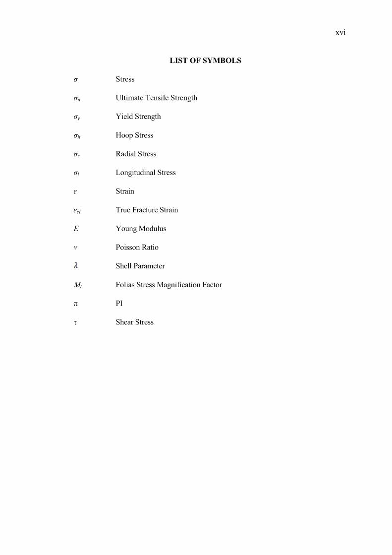
σ Stress
σu Ultimate Tensile Strength
σy Yield Strength
σh Hoop Stress
σr Radial Stress
σl Longitudinal Stress
ɛ Strain
ɛef True Fracture Strain
E Young Modulus
v Poisson Ratio
Shell Parameter
Mt Folias Stress Magnification Factor
π PI
τ Shear Stress
xvii
LIST OF ABBREVIATIONS
API American Petroleum Institute
FE Finite Element
FFS Fitness for Service
ID Internal Diameter
OD Outer Diameter
RP Recommended Practice
SMSC Stress-Modified Critical Strain
UTS Ultimate Tensile Strength
1
CHAPTER 1
INTRODUCTION
1.1 PROJECT BACKGROUND
American Petroleum Institute (API) has classified the pipe for oil and gas. API
X65 steel pipe is one of the pipes that is has been standardized by API and it was largely
used in oil and gas industries. It was used as underground pipelines to transport the
product of oil and gas. Underwater and underground position of the steel pipe makes it
exposed to the salty environment and damp surrounding which can cause corrosion.
During the installation of the pipelines, third party accidents could happen and caused
dents and gouges to the pipelines due to contact of steel-steel and also minor scratches
on the pipe. This thesis will apply the ductile failure criteria proposed by C.-K.Oh et al.
(2007); on gouged API X65 steel pipes in terms of true fracture strain as a function to
the stress triaxiality (defined by the ratio of the hydrostatic stress to the equivalent
stress). To determine the true fracture strain of the pipe, a finite element (FE) modeling
(MSC Patran 2008 r1) of smooth and gouged steel pipe with different gouge length are
tested using FE analysis (MSC Marc). Simulation was made to emulate the variation of
stress triaxiality of the ductile behavior on the material.
From the elastic-plastic deformation of the material, variation of stress triaxiality
which leads to true fracture strains as a function of stress triaxiality can be obtained and
used to determine the burst pressure of a gouged steel pipes. By applying this burst
pressure equation, the stresses subjected to the material due to the internal pressure of
the pipe and the other stresses involved on outer surface of the pipe can be determined.
2
But, in this thesis, the intention goes to the burst pressure of the API X65 steel pipes can
withstand under the defective condition.
1.2 OBJECTIVES OF THE RESEARCH
The main objectives of this project are as follow:
1) To determine the burst pressure of defective API X65 steel pipes.
2) To investigate the effect of gouge length and pipe outer diameter on burst
pressure.
1.3 SCOPE OF PROJECT
The scope of this project concentrates about the determination of burst pressure
of defective steel pipes. API X65 steel pipes with the minimum specified yield strength
and ultimate tensile strength are σy = 448 MPa and UTS = 530 MPa was used for
subjecting the test of the burst pressure. The defect was interpreted as a gouge on the
surface of the steel pipe. Different gouge length was studied to investigate its effect on
the burst pressure of the steel pipes. MSC Patran/Marc was used for FE analysis to by
applying the elasto-plastic isotropic homogeneous material model with reduced
integration. A one-quarter model has been used to represent the full-scale model of the
pipe for computational efficiency
1.4 PROBLEM STATEMENT
API X65 steel pipes is primarily used in the oil and gas industries. The ductility,
high strength and low cost; makes it much more attractive than other type of steel pipe.
Higher-performing steel was used since these industries routinely use miles of pipe.
During the installation of the pipelines, defects are seldom happen which caused by the
third party accidents such as dents and gouges. The pipeline was exposed to the
environment salty sea water and makes it always exposed to the corrosive media.
Corrosion happens, can cause the reduction in thickness of the pipe or in other words is
called metal loss. Metal loss can be very dangerous to the pipeline and which could
cause burst. For this thesis, metal loss from the pipe can be represented as a gouge on
the surface of the pipe.
3
In order to maintain the integrity of the pipe, the burst pressure becomes the
main parameter to be determined. The method to determine the burst pressure was by
using FE analysis software. FE analysis was chosen rather than experimental analysis
because experimental method is very complicated to be done. It requires some
expensive equipment and material. Proper location of experiment is also need to be
considered and it must be equipped with safety measures and acoustic proof, because
the experiment will produce an explosion noise from the burst on the gouge. Using FE
analysis, the test can be done with only by modeling and analyze the model.
4
CHAPTER 2
LITERATURE REVIEW
2.1 INTRODUCTION
A pipe is a tubular section or hollow cylinder, usually but not necessarily
of circular cross-section, used mainly to convey substances which can flow — liquids
and gases (fluids), slurries, powders, masses of small solids. It can also be used for
structural applications; hollow pipe is far stiffer per unit weight than solid members.
Pipes are utilized in various industries and applications. Such usages of steel pipes are
for pipe pilling, road boring, floating docks, fencing, penstock, fiber-optics and drilling.
Some of oil pipeline applications are, oil pipeline API SPEC 5L for the purpose
of transportation of gas, water, oil in oil & gas industry. API SPEC 5CT tubing is used
in extracting petroleum & natural gas casing pipe serves as wall of well. ASTM A106
for the purpose of the pipeline project of boiler, water & petroleum. ASTM A53 it is
used for conveying water, petroleum, gas and other common fluids. ASTM A179 for
tubed heat exchanger and similar heat conveying equipments. ASTM A192 for
manufacture wall panel, economizer, reheater, superheater and steam pipeline of boilers.
In oil and gas industry, most transportation of oil and as product uses a seamless
steel pipes. Seamless steel pipes are a kind of hollow cross-section with no surrounding
joints. It can be used for transmitting a large number of fluids such as oil, natural gas,
water and some solid materials. At the same time it can be widely used as the
manufacture of various structural parts and mechanical parts, such as the drill pipe,
automotive transmission shaft, as well as building construction. Compared with the
5
solid steel such as round bar, at the same flexural torsional strength, the weight of
Seamless steel pipe is lighter. It is a type of economic steel.
2.2 HISTORY
Fracture mechanics is a field of mechanics, concerned with the study of the
propagation of cracks in materials. It uses methods of analytical solid mechanics to
calculate the driving force on a crack and those of experimental solid mechanics to
characterize the material's resistance to fracture. Most engineering materials were
having ductile behavior, and shows some nonlinear elastic and inelastic deformation
under operating conditions that involve larger loads. In such material, the assumptions
of linear elastic fracture mechanics may not hold because of the plastic zone at a crack
tip may have a size of the same order of magnitude as the crack size and the size and
shape of the plastic zone may change as the applied force is increased and also as the
crack length increases.
Therefore, a more general theory of crack growth is needed for elastic-plastic
materials that can account for the local conditions for initial crack growth which
includes the nucleation, growth and coalescence of voids or decohesion at the crack tip.
2.3 API 5L X65
API 5L X65 steel pipes was generally used as a medium to transport the
hydrocarbon products from off-shore to on-shore or on the ground eventually. One
interesting point is that, as most of the API X65 gas pipelines in Korea have been built
within the last 10 years, mechanical properties of API X65 gas pipelines in Korea tend
to have quite uniform properties (Oh C-K et al, 2007). Table 2.1 and 2.2 are the
properties of API X65 steel pipe used in this thesis project.
Table 2.1: Chemical composition of the API X65 steel
Element (wt %)
C P Mn S Si Fe Ceq
0.08 0.019 1.45 0.03 0.31 Balance 0.32
Source: American Petroleum Institute (2000)
6
Table 2.2: Mechanical tensile properties at room temperature of the API X65 steel
Young’s modulus
E (GPa)
Poisson’s Ratio
v
Yield strength
σy (MPa)
Tensile strength
σu (MPa)
210.7 0.3 464.5 563.8
Source: American Petroleum Institute (2000)
2.4 TYPE OF DEFECTS ON STEEL PIPES
Oil and gas transmission pipelines have a good safety record and are a
demonstrably safe means of transporting hydrocarbons. This is due to a combination of
good design, materials and operating practices. However, like any engineering structure,
pipelines do occasionally fail. The major causes of pipeline failures around the world
are external interference and corrosion; therefore, assessment methods are needed to
determine the severity of such defects when they are detected in pipelines (Cosham A,
2004). Assessment methods and determination of the burst pressure before a total lost
could occur are needed to determine the rigorousness of such defects when they are
detected in pipelines.
Figure 2.1: Gouged steel pipe
Source: Cosham A, 2004
7
2.4.1 Gouge
A gouge is defended as a type of chisel with a blade that has a concavo-convex
section. Upon the corrosion process, metal loss from the steel pipe can occur and cause
gouges on the outer surface or inner surface of the pipe. Because of the outer surface of
the steel pipe is much exposed by the surrounding, the corrosion process are more likely
to happen rather than the inner surface. As the gouges happen on the surface of the pipe,
the wall thickness of the steel pipe could reduce and eventually cause in irregularity of
the total shape of that particular pipe.
2.4.2 Dent
A dent in a pipeline is a permanent plastic deformation of the circular cross-
section of the pipe and it is a gross distortion of the pipe cross-section (Cosham A and
Hopkins P, 2004). Dent depth is defined as the maximum reduction in the diameter of
the pipe compared to the original diameter. A dent would cause a local stress and strain
concentration, and a local reduction in the pipe diameter. The dent depth is the most
major factor affecting the burst strength and the fatigue life of a plain dent. The profile
of the dent does not emerge to be a vital parameter, as long as the dent is smooth.
Whether a pipe is gouged during indentation depends on many factors, including
the curve of the indentation, the frictional resistance between the surface of the pipe and
the indenter, the shape and sharpness of the indenter, the pipe geometry, the material
properties and the internal pressure. The stiffer the pipe, the more resistant it is to
denting. Damage introduced into pressurized pipe tends to comprise shallower dents and
deeper gouges than damage introduced into unpressurized pipe, because internal
pressure stiffens the pipe. A sharp indenter is more likely to cut into the pipe wall when
the pipe is pressurized. Experimentally it has been observed that coated and lubricated
pipe surfaces prolong less damage than do dry, bare pipe surfaces.
2.4.3 Corrosion
Corrosion is an electrochemical process. It is a time dependent mechanism and
depends on the local environment within or adjacent to the pipeline. Corrosion usual
8
appears as either general corrosion or localized (pitting) corrosion. There are many
different types of corrosion, including galvanic corrosion, microbiologically induced
corrosion, AC corrosion, differential soils, differential aeration and cracking. Corrosion
causes metal loss.
Corrosion in a pipeline may be difficult to characterize. Typically, it will have an
irregular depth profile and extend in irregular pattern in both longitudinal and
circumferential directions. It may occur as a single defect or as a cluster of adjacent
defects separated by full thickness (un-corroded) material. There are no clear definitions
of different types of corrosion defects. The simplest and perhaps most widely
recognized definitions are as follows: pitting corrosion, defined as corrosion with a
length and width less than or equal to three times the un-corroded wall thickness, and
general corrosion, defined as corrosion with a length and width greater than three times
the un-corroded wall thickness.
2.5 STRESSES ACTED ON STEEL PIPES
A broadly accepted method of predicting tubing failure due to pressure and
tension limits is based on the von Mises stress. If the von Mises stress exceeds the yield
strength of the material, the tubing is assumed to fail. The von Mises stress is a
combination of the three principal stresses in and the shear stress caused by torque. The
three principal stresses are axial stress (σa), radial stress (σr) and Tangential or hoop
stress (σh). There are two types of assumptions made in analyzing these principle
stresses. Those are thin-walled pressure vessel and thick walled pressure vessels. Thin-
walled pressure vessel can be assumed when the ratio of
. Generally, a pressure
vessel is considered to be thin-walled if its radius, r is larger or equal than 10 times its
wall thickness, t. On the other hand, it was assumed that for thick-walled pressure vessel
must have a ratio of
. That means the pressure vessel is considered to be thin-
walled if its radius, r is smaller or equal than 10 times its wall thickness, t.
The coordinates used to describe the cylindrical vessel can take advantage of its
axial symmetry. It is natural to align one coordinate along the axis of the vessel in the
longitudinal direction). To analyze the stress state in the vessel wall, a second
coordinate is then aligned along the hoop direction. With this choice of axisymmetric
9
coordinates, there is no shear stress. The hoop stress σh and the longitudinal stress σl are
the principal stresses.
Figure 2.2: Direction of hoop and longitudinal stress
Source: Beer FP, Jr. Johnston ER, De Wolf JT (2006)
2.5.1 Hoop Stress
A circumferential stress which, in a pipe or pressure vessel would tend to make
the pipe diameter or circumference increases. As fluid which has filled the pipe is
pressurized the hoop stress causes the diameter or circumference to increase. The force
resisted by the tangential stress can be called as hoop stress and it is acting uniformly
over the stressed area for thin-walled pressure vessel. The free body is in static
equilibrium. According to Newton's first law of motion, the hoop stress yields;
10
Figure 2.3: Ratio of pipe radius to pipe thickness
Source: Beer FP, Jr. Johnston ER, De Wolf JT (2006)
But, if the cylindrical pipe or pressure vessel has a ratio of
, the cylinder can be
considered as a thick-walled vessel and the hoop stress of the cylinder is equal to the
tangential stress;
σ
Figure 2.4: Hoop stress acted on steel pipe
Source: Beer FP, Jr. Johnston ER, De Wolf JT (2006)
11
2.5.2 Radial Stress
When the assumption for thin wall states that if
t , the ratio of the internal
radius of the pipe and the thickness is less than 10. The stress acted on the z axis is
equal to zero (0), , and thus the radial stress σr will also equal to zero
because the radial stress acted on the pipe is rotated along the z-axis.
2.5.3 Axial Stress
Defined as, the tension or compression stress created in a structural member by
the application of a lengthwise axial load. Sometimes, axial stress also called as
longitudinal stress.
Figure 2.5: Longitudinal stress acted on steel pipe
Source: Beer FP, Jr. Johnston ER, De Wolf JT (2006)
To determine the longitudinal stress σl, we make a cut across the cylinder similar
to analyzing the spherical pressure vessel. The free body, illustrated on the above, is in
static equilibrium. This implies that the stress around the wall must have a resultant to
balance the internal pressure across the cross-section.
Applying Newton's first law of motion, we have,
σ
12
σ
The equation stated above can only be used if the pipe or pressure vessel is assumed as
a thin-walled.
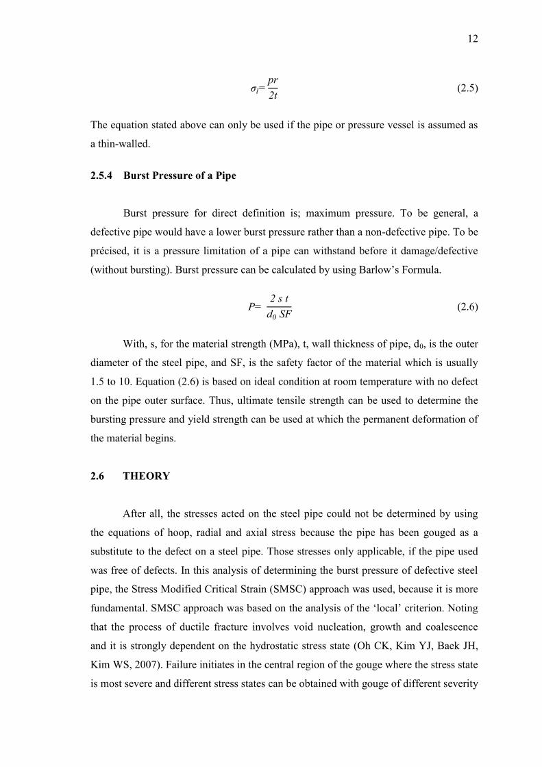
2.5.4 Burst Pressure of a Pipe
Burst pressure for direct definition is; maximum pressure. To be general, a
defective pipe would have a lower burst pressure rather than a non-defective pipe. To be
précised, it is a pressure limitation of a pipe can withstand before it damage/defective
(without bursting). Burst pressure can be calculated by using Ba low’s Fo mula
With, s, for the material strength (MPa), t, wall thickness of pipe, d0, is the outer
diameter of the steel pipe, and SF, is the safety factor of the material which is usually
1.5 to 10. Equation (2.6) is based on ideal condition at room temperature with no defect
on the pipe outer surface. Thus, ultimate tensile strength can be used to determine the
bursting pressure and yield strength can be used at which the permanent deformation of
the material begins.
2.6 THEORY
After all, the stresses acted on the steel pipe could not be determined by using
the equations of hoop, radial and axial stress because the pipe has been gouged as a
substitute to the defect on a steel pipe. Those stresses only applicable, if the pipe used
was free of defects. In this analysis of determining the burst pressure of defective steel
pipe, the Stress Modified Critical Strain (SMSC) approach was used, because it is more
fundamental SMSC app oach was based on the analysis of the ‘local’ c ite ion Noting
that the process of ductile fracture involves void nucleation, growth and coalescence
and it is strongly dependent on the hydrostatic stress state (Oh CK, Kim YJ, Baek JH,
Kim WS, 2007). Failure initiates in the central region of the gouge where the stress state
is most severe and different stress states can be obtained with gouge of different severity