Nepal Journal of Civil Engineering Volume: 1(1) January 2021 ISSN: 2773-806X Determination of Forces on Anchor Blocks and Stability Analysis in a 3 Dimensional Plane with Vector Approach Gaurav Atreya a , Narendra Man Shakya b a Department of Civil Engineering, Pulchowk Campus, Institute of Engineering, Tribhuvan University, Nepal; Currently at: AI Department, Eydean Inc., Kathmandu, Nepal b Department of Civil Engineering, Pulchowk Campus, Institute of Engineering, Tribhuvan University, Nepal Corresponding Email: a [email protected], b [email protected]Received: 2020-03-10 Final Revision: 2020-12-29 Accepted: 2020-12-30 Abstract The Anchor blocks are the structures that take most of the forces acting on the pipe bends and transfer it safely to the ground. Since the stability of the Anchor Blocks is a function of its weight, the economic design comes with accurate calculation of the forces. Although several sources have the design calculations for Anchor Blocks, there is room for improvements for 3D calculations. The calculation of the forces is hard to visualize in a two-dimensional plane as numerous planes have to be made for the analysis. The purpose of this paper is to use the 3D vector mechanics so that forces can all be represented by global vectors in X, Y & Z direction and henceforth are easy to study. By doing so the intermittent calculations, as well as the end results, are efficient, coherent and scalable (to any number of a joint like T-joint, or combination of bends and joints). The formulae and procedures are developed with consideration of developing a well-organized CAD-based software for an even better analysis of a variety of irregular shapes in the future with reduced human efforts. Keywords Anchor Blocks, Hydropower, Pipelines, Vector Mechanics 1. Introduction All types of above-ground penstock are secured in place at points by anchor blocks. Anchor blocks are the structures which represents the fixed supports of the penstock and are located at vertical or horizontal bends (Mosonyi, 1991). In reality however, there aren’t just the cases of individual horizontal and vertical bend but the mixture of both, specially due to the difficult terrains and budget problems in case of Nepal. The pipelines mainly considered on this paper are the high pressure or low pressure penstocks of hydro-power water conveyance systems, but will also be applicable to analogous systems. The main forces on the anchor blocks are from the dead weights, hydro-static forces, the earth pressures and seismic forces(if considered). There are many other minor forces, which are considered here although a good enough result can be obtained with only the major ones. Although some optimization has been done to get empirical equations(Al-Gahtani, 2009), the 3D approach for the analysis has been rare. Sundberg (2013) has taken 3D approach to calculate the co-ordinates and forces which is based on ASCE (2012). But the vectors are defined only locally and used for determining the important co-ordinates of Anchor Block; so expanding the use of those vectors to calculation of forces, we can avoid the need to resolve the forces in any planes. 2. Materials and Methods The basic definition of the forces which acts on the Anchor Block as per guidelines (ASCE, 2012, Kisan et al., 1984) were used to developed their formula in 3D. Then the design and analysis steps were then modified to accommodate the new formulae. The formula and derivations in this paper are based on these premises. 1. Forces are transferred from pipe to the anchor blocks and then to the ground. 2. Other supports besides the anchor blocks are the saddle supports for exposed pipelines and the earth itself for the buried ones. Pages: 19 – 32
Transcript
Nepal Journal of Civil EngineeringVolume: 1(1) January 2021 ISSN: 2773-806X
Determination of Forces on Anchor Blocks and StabilityAnalysis in a 3 Dimensional Plane with Vector Approach
Gaurav Atreya a, Narendra Man Shakya b
a Department of Civil Engineering, Pulchowk Campus, Institute of Engineering, Tribhuvan University, Nepal;Currently at: AI Department, Eydean Inc., Kathmandu, Nepal
b Department of Civil Engineering, Pulchowk Campus, Institute of Engineering, Tribhuvan University, NepalCorresponding Email: a [email protected], b [email protected]
Received: 2020-03-10 Final Revision: 2020-12-29 Accepted: 2020-12-30
AbstractThe Anchor blocks are the structures that take most of the forces acting on the pipe bends and transfer itsafely to the ground. Since the stability of the Anchor Blocks is a function of its weight, the economic designcomes with accurate calculation of the forces. Although several sources have the design calculations forAnchor Blocks, there is room for improvements for 3D calculations. The calculation of the forces is hard tovisualize in a two-dimensional plane as numerous planes have to be made for the analysis. The purpose ofthis paper is to use the 3D vector mechanics so that forces can all be represented by global vectors in X, Y & Zdirection and henceforth are easy to study. By doing so the intermittent calculations, as well as the end results,are efficient, coherent and scalable (to any number of a joint like T-joint, or combination of bends and joints).The formulae and procedures are developed with consideration of developing a well-organized CAD-basedsoftware for an even better analysis of a variety of irregular shapes in the future with reduced human efforts.
All types of above-ground penstock are secured inplace at points by anchor blocks. Anchor blocks are thestructures which represents the fixed supports of thepenstock and are located at vertical or horizontal bends(Mosonyi, 1991). In reality however, there aren’t justthe cases of individual horizontal and vertical bendbut the mixture of both, specially due to the difficultterrains and budget problems in case of Nepal.
The pipelines mainly considered on this paper are thehigh pressure or low pressure penstocks ofhydro-power water conveyance systems, but will alsobe applicable to analogous systems. The main forceson the anchor blocks are from the dead weights,hydro-static forces, the earth pressures and seismicforces(if considered). There are many other minorforces, which are considered here although a goodenough result can be obtained with only the majorones. Although some optimization has been done toget empirical equations(Al-Gahtani, 2009), the 3Dapproach for the analysis has been rare. Sundberg(2013) has taken 3D approach to calculate the
co-ordinates and forces which is based on ASCE(2012). But the vectors are defined only locally andused for determining the important co-ordinates ofAnchor Block; so expanding the use of those vectorsto calculation of forces, we can avoid the need toresolve the forces in any planes.
2. Materials and Methods
The basic definition of the forces which acts on theAnchor Block as per guidelines (ASCE, 2012, Kisanet al., 1984) were used to developed their formulain 3D. Then the design and analysis steps were thenmodified to accommodate the new formulae.
The formula and derivations in this paper are based onthese premises.
1. Forces are transferred from pipe to the anchorblocks and then to the ground.
2. Other supports besides the anchor blocks are thesaddle supports for exposed pipelines and theearth itself for the buried ones.
Pages: 19 – 32
Determination of Forces on Anchor Blocks and Stability Analysis in a 3 Dimensional Plane with VectorApproach
3. The radius of curvature of the pipe is very smallcompared to the head of water in the bend, so thehead can be assumed constant over the length ofa bend.
4. The diameter of pipe is very small compared tothe head of water, so the water pressure can beassumed constant over the cross section. Thus,the net resultant of pressure is at the geometriccenter.
5. The friction force taken for the calculations isthe maximum amount which can develop, thefriction force on itself can never exceed thetotal of sliding forces and acts on the oppositedirection of the strain produced.
6. The water hammer effect is considered as addeddynamic head to the static head, the temporalvariation of the force is not considered.
These assumptions will help simplify the calculationof magnitude of the forces associated with the AnchorBlocks, as for the direction of the force vectors weneed a way to represent their direction in a moreunified way.
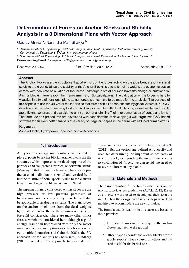
2.1 Co-ordinate Systems
Since the direction of forces developed in anchorblocks depends upon the directional alignment of thepipes and blocks, two local co-ordinate systems aredefined in terms of the global system to make all thoseforces compatible with one another. The definition ofthe forces are in local scope, the local system definedhere will be used to convert those forces into globalones.
The forces are expressed in terms of the globalco-ordinate systems of i, j and k which are the unitvectors along the direction of X, Y and Z axisrespectively. Every force consists of three componentsand can be expressed as F = FX i+FY j +FZ k. TheEasting, Northing and Elevation are taken as the X, Yand Z co-ordinates respectively. Using of anyprojection system will have satisfactory resultalthough mUTM (modified UTM) co-ordinate systemwith Everest Nagarkot datum is used for the examples.
First local Co-ordinate system written from hereonward as Local Co-ordinate system-I has threemutually perpendicular axes one along the flowdirection of the water (r1), another perpendicular tothe first one and lying completely in the vertical plane
passing through the pipe (r2) and the last oneperpendicular to the both-that would be left of thepipe horizontally (r3). The two vectors r1 & r2 lieperpendicularly in the vertical plane.
Second local Co-ordinate system written from hereonward as Local Co-ordinate system-II consists ofone unit vectors each from Global and First LocalSystem which are the unit vector along positive Z axis(k) and unit vector perpendicular to the pipe in thehorizontal plane (r3), the new unit vector is the unitvector along the direction of the pipe in the horizontalplane (rp). The two vectors r3 & rp lie perpendicularlyin horizontal plane.
The directions of these vectors are illustrated in figures2 & 3.
Representing a force’s r1 component similarly asrepresenting X component of force F as ~FX wouldcause problems and some unaesthetic symbols, so forsimplicity, let’s define a vector operation ∗ whichgives the vector component of first operand to thesecond operand. Mathematically it can be expressedas,
~A∗~B = (~A ·~B)~B (1)
As shown in figure 1,when the second operand is aunit vector this operation results in the rectangularcomponent of the first operand to the second (~F ∗ i issame as ~FX ).
Figure 1: Demonstration of * operator
Hence, the direction of the given expression is alwaysthe direction of vector given after ∗ operator.
Conversion of Local Systems in to Global Systemcan be done by considering a pipe with center pointspanning between two Point of Intersections(PI)PI1(x1,y1,z1) and PI2(x2,y2,z2). The relationshipsbetween aforementioned vectors can be calculatedusing trigonometry and co-ordinate geometry :The r1 vector along the flow direction is thedisplacement vector from start to end of the
20
Nepal Journal of Civil Engineering
pipe(center point). Hence, it is given as unit directionof displacement vector from PI1 to PI2.
r1 =x2− x1
li+
y2− y1
lj+
z2− z1
lk (2)
Similarly, rp & r2 can be calculated as per theirdefinitions.
rp =x2− x1
lpi+
y2− y1
lpj+0k (3)
r2 = sin(α)rp− cos(α)k
= (k× rp)× r1 (4)
r3 = r1× r2 = k× rp (5)
Where l & lp are the total length and length in plan ofthe pipe segment. Which can be calculated as;
l =√(x2− x1)
2 +(y2− y1)2 +(z2− z1)
2 (6)
lp =
√(x2− x1)
2 +(y2− y1)2 (7)
And α is the angle made by flow direction to thehorizontal plane.
α = arctan(z2− z1
lp) (8)
Figure 2: XY(i) & YZ(ii) projections of differentaxes
Figure 3: Isometric views of different axes
For the moment calculation, the point of applicationof forces are also required. The most used Points are:
Pj(x j,y j,z j) PI of bend
Pju(x ju,y ju,z ju) u/s PI of bend
Pjd(x jd ,y jd ,z jd) d/s PI of bend
Pi(xi,yi,zi) Center of toe of ith
face of Anchor Block
PCG(xCG,yCG,zCG) CG of Anchor Block
Other points can be easily determined using geometricrules if need arises.
2.2 Forces on Anchor Block
The Anchor blocks’ main function is to providestability from forces in the pipe and environment. Itexperiences a variety of forces from water inside thepipe, pipe itself, earth surrounding it and the water inthe earth. Some of these forces are Major Forceshaving significant part in resultant, while others canbe ignored for approximation. Some forces might bemajor in some conditions and insignificant in other.
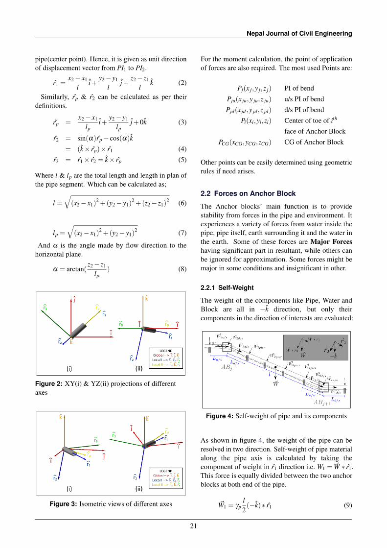
2.2.1 Self-Weight
The weight of the components like Pipe, Water andBlock are all in −k direction, but only theircomponents in the direction of interests are evaluated:
Figure 4: Self-weight of pipe and its components
As shown in figure 4, the weight of the pipe can beresolved in two direction. Self-weight of pipe materialalong the pipe axis is calculated by taking thecomponent of weight in r1 direction i.e. W1 = ~W ∗ r1.This force is equally divided between the two anchorblocks at both end of the pipe.
~W1 = γpl2(−k)∗ r1 (9)
21
Determination of Forces on Anchor Blocks and Stability Analysis in a 3 Dimensional Plane with VectorApproach
Only unit weight of pipe (γp) is taken as water is freeto move in r1 direction. ~W1u/s & ~W1d/s are calculatedwith respective r1 & l.
Similarly, self-weight of pipe and water perpendicularto the pipe axis is the component along r2 directioni.e. W1 = ~W ∗ r2. But a major difference except thedirection is that the perpendicular component is sharedamong the saddle supports so only the length betweenthe Block and nearest saddle is used for Fweight unlikein equation 9 where total length between PI is taken.The reason being that this component of weight isdistributed between the piers along the pipe length aswell asthe Anchor Blocks at the ends.
~W2 = γp+wL2(−k)∗ r2 (10)
Again, ~W2u/s & ~W2d/s are calculated with respectiver2 & L.Self-weight of Anchor Block is used for the stabilityanalysis, it provides most amount of stabilizing forceand moment. It can be calculated as unit weightmultiplied by volume of block. Summation ofdifferent parts can be done if it consists of more thanone material.
~WB =−γconcVBk (11)
2.2.2 Hydro-static Forces
Hydro-static forces in penstock that we need toconsider are due to bend and reducer. Same principlecan be applied in case of other type of joints. In astraight part of pipe, the hydro-static forces of waterwill be cancelled out in the direction of flow. Theremaining hydro-static force is radially outward. Thatforce will be balanced by hook’s stress of pipe and haszero resultant.But in case of bend, the force on flow directiondoesn’t get canceled out due to change in direction, itcan be determined by taking the integration of all thehydro-static forces in the length of bend. Whichyields,
~Hb = ρwgZA(r1u/s− r1d/s) (12)
The sign convention is +ve for incoming and −ve foroutgoing pipes, since a bend has two pipes a simplevector difference will suffice.
Similarly in case of reducer, the change in area in entryand exit yields some residual hydro-static force given
by,
~Hr = ρwgZ(Au/s−Ad/s)(r1u/sORr1d/s) (13)
The variation in pressure throughout the pipe sectionand length (Munson et al., 2009) are considered to beinsignificant in case of huge head (Z).
Figure 5: Directions of Hydrostatic Forces onhorizontal bend (i) and reducer (ii)
2.2.3 Seismic Forces
Seismic forces are the forces developed due to relativemovements between the block and the earth. AsNepal has been vulnerable to Earth quakes due to itsgeological structures(Pandey et al., 1995), and has hadrecent event of major earthquake in 2015 (Bhattaraiet al., 2015), the seismic forces are major forces indesign/analysis of any structure.The horizontal seismic force is calculated by takingthe multiplication of weight by horizontal seismiccoefficient.
SH = KHWB (14)
The direction of horizontal is unknown till the point ofimpact, so for critical condition the direction can betaken as the direction of resultant force to produce themaximum sliding force.Similarly, vertical seismic force is the multiplicationwith vertical seismic coefficient. The direction of forcecan be taken upward for critical condition as downwardforce would increase stability.
~SV = KVWB(±k) (15)
Figure 6: Seismic forces in plan (i) and section alongcenterline (ii)
22
Nepal Journal of Civil Engineering
In figure 6 the θ angle is arbitrary as the seismic forcecan act on any direction at the time of earthquake andhence for analysis it should be taken in a directionthat is most critical to the structure, for now that is thesame direction of resultant as it’d maximize the slidingforce. Also, the point of application of seismic force isthe Center of Gravity of the Anchor Block, the pointof application of resultant may be different.
2.2.4 Force from Earth Pressures
Earth pressure is unavoidable since the blocks rest onthe earth itself. In certain conditions the pressure fromthe earth can help establish the block but sometimes itcan be major force in destabilizing. Since forces dueto earth pressures are more in opposite direction ofdisplacement, most of the time it is resisting in nature.The earth pressure is directly dependent on the depthof the soil, hence its distribution is triangular (Arora,1987). The total force due to soil of depth h can becalculated by equation 16. This force acts at a point1/3rd from the bottom vertically and at the center offace horizontally. This force acts on each face of theblock, the force on the ith face due to the soil touchingit can be calculated as:
~Ei =12
kγslih2(−ni) (16)
Here, the unit vector ni is perpendicular to the faceof the block on which the pressure is acting. Thedirection of unit vector is outward from the surface ofthe block as shown in figure 7(ii).
Figure 7: Direction of forces due to earth pressure
In the case that the soil is saturated, submerged unitweight of soil (γ ′s) is used instead of (γs).Here k is the coefficient of earth pressure whichdepends on the direction of movement of block. If Ris the resultant force causing the displacement,
k =
ka for (~R· ni)< 0kp for (~R· ni)> 0k0 for (~R· ni) = 0
Since we don’t want the block to actually start sliding(which means stability-failure) at-rest coefficient ofearth pressure (k0) instead of passive earth pressure(kp) is used in design for (~R· ni)≥ 0.
2.2.5 Ground Water Up-thrust
When the ground is saturated, it not only reduces theCoefficient of friction, it can also give the up-thrustwhich helps reduce the vertical component of resultant.This force doesn’t need to be considered if the site hasgood drainage.
And the Upthrust force on the base in that conditioncan be calculated as the weight of the water displaced,i.e. if the volume of block under the ground waterlevel (shaded part in figure 8) is V then the upthrustU is equal to γwV (Munson et al., 2009) acting on theCG of the displaced water in k direction.
Figure 8: Ground Water Forces acting on a Block(forces on only u/s and d/s faces)
Assuming horizontal level of water at height of h fromanchor block base, the upthrust force for a block withprojected base area of A can be calculated as,
~U = cγwhAbase(k) (17)
While, the horizontal water force on ith face can becalculated with formula for water force (Munson et al.,2009),
~Pi =12
γwli ∗h2i (−ni) (18)
When the water level doesn’t vary between the facesof the block the resultant horizontal resultant (vectorsum of all forces given by equation 18) is zero.
23
Determination of Forces on Anchor Blocks and Stability Analysis in a 3 Dimensional Plane with VectorApproach
2.2.6 Hydrodynamic Forces
The forces due to change in the direction ofmovement of the water is given by the rate of changeof the momentum of the water Munson et al. (2009).Same as hydro-static forces hydrodynamic forces arealso calculated for two cases.Hydrodynamic forces in a bend is again theintegration of moment change over the span of bend.Which yields,
~Hb−dyn = ρwQv(r1u/s− r1d/s) (19)
Similarly hydrodynamic forces in a reducer is thechange in momentum due to velocity change,
~Hr−dyn = ρwQ(vu/sr1u/s− vd/sr1d/s) (20)
The direction of these forces are same as thehydrostatic forces, which are illustrated in figure 5.
2.2.7 Thermal Forces
Thermal fores are developed due to change in thelength of the pipe which in turn is caused by thechange in the temperature of the environment. In caseof the buried pipes the temperature variation isn’tsignificant, and in case of expansion joints, this forceis used in conjunction with the frictional force.
Figure 9: Thermal forces during expansion
~FT = ApE∆T αL(r1u/s− r1d/s) (21)
Here, Ap = πDt is the cross-sectional area of pipematerial.
Although thermal forces will be nullified at expansionjoints, the friction resisting the transfer of the strain tothe expansion joint will make the direction of frictionforce opposite to the strain from temperature change.If no expansion joints are provided thermal forces act
directly to the blocks at the two ends (friction forcesaddles help to distribute the force as shown in figure9). But the friction force can be neglected as it is onlyresistive in nature and the thermal force is consideredto act directly on the Blocks. But in the case thatExpansion joint is provided the Thermal force isneutralized at the joint, but the frictional force resiststhe neutralization and becomes important.
2.2.8 Frictional Forces
Since frictional force is resistive in nature it mostlyacts to help the stability by decreasing other forces.For example if only self weight of pipe was to act onit, the friction along the piers will act upwards to resistthe pipe sliding downwards from self weight. So, insuch cases this force can be neglected.
It becomes a major destablizing force when expansionjoints are provided because it resists the release ofthermal force on expansion joints.In case of pipes with expansion joints, the stress due toexpansion/contraction is canceled out only if it travelsto the expansion joint, so the friction with the saddlecan prevent the force transfer and add that force toAnchor Block.
Figure 10: Frictional forces
In such case the frictional force is the minimum ofthermal forces developed and maximum frictionalresistance. While in case without expansion joint thisforce can help reduce the transfer of thermal forceinto the Anchor Blocks, but that condition is notconsidered as it favors the stability.The maximum amount of resisting force a single piercan provide in this condition can be calculated as,
~fmax = µsγp+w(Lpier r2 · k)r1 (22)
Here, Lpier is the distance between the piers, and thetotal frictional force can be found out by multiplyingthis with number of piers.For friction with soil where piers are not present, the
Where, α and β are coefficients ranging from -1 to +1;their sign are +ve and -ve according to the directionof movement of pipe respective to saddle. And theirmagnitude depends on whether the expansion jointsare present or not. If expansion joints are not providedtake α = β = 0.5; otherwise, take the coefficients asthe ratio of distance to the expansion joint to the totaldistance to the next anchor block in respective sides(shown in figure 10).
It is important to note that, these values are maximumamount of friction force and actual friction force cannever surpass the force it is resisting. So, the actualfriction force can not exceed the value of ThermalForce if expansion joint was absent (as given fromequation (21)).
2.2.9 Provision for Other Forces
Extra forces (like force on rock anchorages) forspecial conditions can be added as a vector asspecified in the procedure below, the point of actionand the vector form of the force has to be developedbefore proceeding. Because of that, the characteristicsof the force has to be known before adding it to thismodel.
2.2.10 Calculation of Resultant
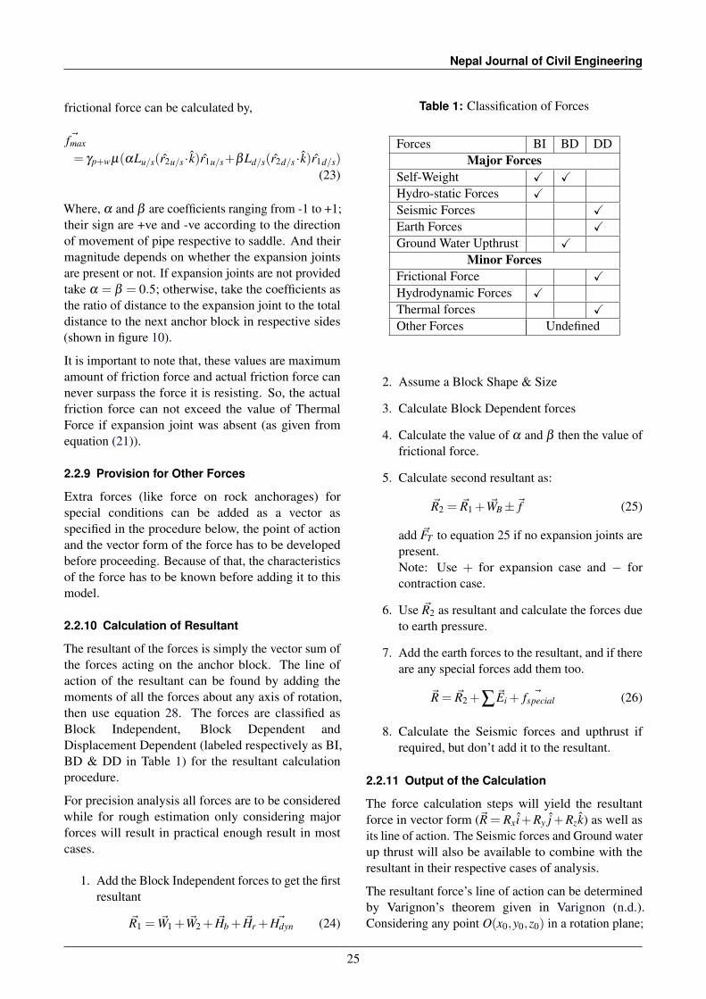
The resultant of the forces is simply the vector sum ofthe forces acting on the anchor block. The line ofaction of the resultant can be found by adding themoments of all the forces about any axis of rotation,then use equation 28. The forces are classified asBlock Independent, Block Dependent andDisplacement Dependent (labeled respectively as BI,BD & DD in Table 1) for the resultant calculationprocedure.
For precision analysis all forces are to be consideredwhile for rough estimation only considering majorforces will result in practical enough result in mostcases.
1. Add the Block Independent forces to get the firstresultant
~R1 = ~W1 + ~W2 + ~Hb + ~Hr + ~Hdyn (24)
Table 1: Classification of Forces
Forces BI BD DDMajor Forces
Self-Weight X XHydro-static Forces XSeismic Forces XEarth Forces XGround Water Upthrust X
Minor ForcesFrictional Force XHydrodynamic Forces XThermal forces XOther Forces Undefined
2. Assume a Block Shape & Size
3. Calculate Block Dependent forces
4. Calculate the value of α and β then the value offrictional force.
5. Calculate second resultant as:
~R2 = ~R1 + ~WB±~f (25)
add ~FT to equation 25 if no expansion joints arepresent.Note: Use + for expansion case and − forcontraction case.
6. Use ~R2 as resultant and calculate the forces dueto earth pressure.
7. Add the earth forces to the resultant, and if thereare any special forces add them too.
~R = ~R2 +∑~Ei + ~fspecial (26)
8. Calculate the Seismic forces and upthrust ifrequired, but don’t add it to the resultant.
2.2.11 Output of the Calculation
The force calculation steps will yield the resultantforce in vector form (~R = Rx i+Ry j+Rzk) as well asits line of action. The Seismic forces and Ground waterup thrust will also be available to combine with theresultant in their respective cases of analysis.
The resultant force’s line of action can be determinedby Varignon’s theorem given in Varignon (n.d.).Considering any point O(x0,y0,z0) in a rotation plane;
25
Determination of Forces on Anchor Blocks and Stability Analysis in a 3 Dimensional Plane with VectorApproach
we can calculate the moment of all the forces aroundthe rotation axis as:
~M = ∑~ri×~Fi =~r×~R (27)
Here,~ri = Pi−O where ri,Pi&Fi are the moment arm,point of action of ith force and that force respectively,while ~r and ~R are lever arm of resultant and theresultant. If r is the perpendicular distance from O tothe line of action of the force,
r =|~M||~R|
(28)
2.3 Stability Analysis
After the calculation of all the forces, the stability ofthe block can be calculated in different cases usingmany parameters. The cases considered for thestability analysis are Expansion case (E), Contractioncase (C), Seismic case (S) and Ground water saturatedcase (G). Other cases can also be used for analysis ifconditions and combination of forces are known forthat case, usually it’s superfluous to analysis fornon-critical cases.
The numerical parameters calculated for determiningthe safety are, Factor of Safety against Sliding,Overturning, eccentricity and the pressure at the baseof the block. The factor of safety against sliding in asliding direction s is calculated as,
FoS = µ~R · p~R · s
(29)
Here, R is the resultant force of all the forces on theblock, and p is the unit vector perpendicular to thesliding plane(towards the plane).
For horizontal sliding plane, the minimum factor ofsafety is when the direction of slide is same as thehorizontal direction of resultant. So equation 29becomes,
FoSmin = µ−Rz√
(Rx)2 +(Ry)2(30)
Here in equation 29 & 30, ~R = Rx i+Ry j+Rzk is thetotal resultant force.When seismic conditions are considered, SH is addedto the denominator and SV is subtracted fromnumerator (in a way that results in least FoS). Andwhen Ground water is considered, U is subtractedfrom the numerator (value of µ is also likely tochange)
Now, to analyze the safety against overturning, themoment of all the forces are calculated with theformula,
~M =~r×~F (31)
Where, r is the vector joining the point of rotation andthe force(F) in the rotating plane. Taking a unit vectorpointing out from the rotating plane m in the samedirection as overturning rotation axis, Factor of safetywhich is defined as the ratio of resisting moment tooverturning moment (Arora, 1987):
FoS =−∑−ve ~M· m∑+ve ~M· m
(32)
Where the sum of positive represents overturningmoment, while negative is stabilizing moment.
When seismic conditions are considered, effects ofSH & SV are taken as they act at CG of block. Theirdirection is again taken in such a way that they producemaximum overturning moment.
When ground water is considered, effect of U is addedconsidering it acts on CG of base.
The check for eccentricity is that the line of actionshould pass through the middle third of the base of theblock.
The intersection of line of action of the resultant withthe base of the Block is the point of action of the forcein the base. Now eccentricity can be found out bydetermining the horizontal distance between the pointof action and the center of the base. This eccentricity isthen used to check the bearing pressures at each vertexof base. The bearing pressures should lie between zeroand Bearing capacity of the soil.
3. Results and Discussions
The formulae and procedures for the Design andAnalysis of the Anchor Blocks are derived using thevector approach. Those formulae were verified byconverting them to the trigonometric formulae in a 2dsetting. The trigonometric formulae for the analysiscan be found in many guidelines and are easier to beverified.
3.1 Verification Using Trigonometric Method
As trigonometric method is little complicated for 3D,we can assume Y co-ordinates of the pipe to be samefor comparison, so there is only vertical deflection.
26
Nepal Journal of Civil Engineering
The formulae for the unit vectors in 2.1 will have (y2−y1) = 0. The equation 2 becomes,
r1 =x2− x1
li+
z2− z1
lk (33)
Similarly, rp is just i and r3 is j. While, r2 is stillj× r1.
Now, if we use vertical deflection angle α to convertco-ordinate differences to trigonometric functions.We’ll have,
tan(α) =z2− z1
x2− x1(34)
sin(α) =z2− z1
l(35)
cos(α) =x2− x1
l(36)
Where, l =
√(x2− x1)
2 +(z2− z1)2 is the length
between the PI. Now, redefining the r1 vector:
r1 = cosα i+ sinα k (37)
And, r2 vector:
r2 = sinα i− cosα k (38)
Let’s assume (αu/s,αd/s) as (α,β ) in this section forsimplicity.
Now replacing the values of the unit vectors in 2dimension in the formulae of forces from 2.2Forceson Anchor Block.
Replacing the values of unit vectors in Self-Weightforces from section-2.2.1 we can get the trigonometricformulae as given in Kisan et al. (1984) and DOEDDesign Guidelines: Water Conveyance System ofHydropower Projects (2007).
Equation 9 after substitution:
~W1 = γpl2(−k) · (cosα i+ sinα k)r1
= −γpl2
sinα r1
So, the self weights along the flow direction due toupstream and downstream pipe segment can beexpressed as:
W1u/s = γplu/s
2sinα (39)
W1d/s = γpld/s
2sinβ (40)
Similarly, equation 10 becomes:
~W2 = γp+wL2(−k) · (sinα i− cosα k)r2
= −γp+wL2
cosα ∗ r2
W2 due to upstream and downstream pipe segmentsare now:
W2u/s = γp+wLu/s
2cosα (41)
W2d/s = γp+wLd/s
2cosβ (42)
The self weight of Anchor Block WB is simply γconcVB,which doesn’t need conversion.
Hydrostatic Forces The forces from section 2.2.2 canalso be converted in similar manner. The hydrostaticforce on bend after replacing the values of unit vectorsis:
~Hb = γwZA(cosα i+ sinα k− cosβ i− sinβ k)
Now, magnitude of the force given by square root ofthe sum of squares of the components is,
Hb = γwZA√
(cosα− cosβ )2 +(sinα− sinβ )2
(43)
Now, expanding and replacing cos2 θ + sin2θ by 1,
we get,
= γwZA√
1−2cosα cosβ +1−2sinα sinβ
Now, we know that cos(α − β )= cosα cosβ + sinα sinβ & cos2θ = 1−2sin2
θ ,
= γwZA√
2−2cos(α−β )
= γwZA
√2−2(1−2sin2(
α−β
2))
Finally, we get the hydro-static force in a bend as:
Hb = 2γwZAsin(|α−β |
2) (44)
For Hydrodynamic Forces, using the evaluationsfrom equation 43 to 44 we can directly write,
|r1u/s− r1d/s|= 2sin(|α−β |
2) (45)
27
Determination of Forces on Anchor Blocks and Stability Analysis in a 3 Dimensional Plane with VectorApproach
Thus, the hydrodynamic force from 2.2.6 can now beredefined as,
Hdyn = 2ρwQvsin(|α−β |
2) (46)
replacing the value of velocity(v) in terms ofdischarge(Q) & diameter(d), we get,
Hdyn = ρw8Q2
πd2 sin(|α−β |
2) (47)
As for the frictional forces from section 2.2.8,replacing the unit vectors yields,
~fmax = µsγp+wLpier((sinα i− cosα k) · k)r1
Which evaluates to µsγp+wLpier(cosα)∗ r1, thereforethe magnitude of the friction force is,
fmax = µsγp+wLpier(cosα) (48)
3.2 Sample Calculation
Now, Using the methods described before, a samplecalculation was done for a T-joint with a Bendimmediately following. Calculation of which wouldhave been very tedious with trigonometric methods.The units of Forces, Moments and Lengths are in kN,kN−m & m respectively.
The main inputs are the hydraulic parameters and thealignment geometry. For a calculation/analysis of along alignment, only varying the contents of table 3will give all the block independent forces. The designparameters are shown in table 2, for a project this tablemostly remains same, the pipe diameter and the totalhead may defer for headrace pipe and penstock pipe.
Using the co-ordinates given in table 3 we cancalculate the unit vectors in local co-ordinate systemfor all the pipes, the important ones are: Headrace toTee(P1), Bend to Penstock(P2), Tee to SurgeTank(P3),their unit vectors are given in table 4. After the unitvectors are calculated, the hydro-static forces of thosepipes can be calculated using the formula given inequation 12. The point of actions for these forcesshown in table 5 are respectively Tee, Bend and Teepoint. Similarly, all the other forces can be calculatedas per section 2.2, and we’ll get their vector form aswell as point of application.
Now, a shape of Anchor Block is assumed (anditeratively modified till all safety parameters arewithin satisfactory limit).
Table 2: Design Parameters
Description Symbol ValueInternal Diameter D 1200 mmThickness t 8 mmOuter Diameter Do 1216 mmInternal Area A 1130973 mm2
Steel Area As 30360 mm2
Steel Density ρs 7.85 kg/m3
Water Density ρw 1 kg/m3
Crest Level CL 1409.5 amslStatic Head Z0 15.85 mDynamic Head Zdyn 20 mTotal Head Z 35.85 mWeight of Water γw 11.09 kN/mWeight of Pipe γp 2.34 kN/mTotal Weight γw+p 13.43 kN/mSoil Density γsoil 18 kN/m3
Angle of Friction φ 22.5 ◦
Active Coeff. Ka 0.4465At-rest Coeff. K0 0.6173Passive Coeff. Kp 2.2398
Start Pt. X Y Lengthface A 425794.78 3069488.60 2.26face B 425795.28 3069486.40 2.20face C 425793.88 3069484.69 3.08face D 425791.50 3069486.65 1.33face E 425790.61 3069487.65 1.32face F 425790.01 3069488.82 2.22face G 425792.00 3069489.79 1.90face H 425793.08 3069488.22 1.74
This co-ordinates shown in table 6 describe the shapeas seen in figure 12. Here the height of the block alsovaries between the edges (not shown in figure). Thevolume of Block was 49.38m3, CG at(425792.942,3069487.2734,1394.0166) and totalweight of Block including water and pipe directlyinside it comes out to be −1116.6~k. All of thesemeasurements are taken from a CAD software.
With these co-ordinates of the points, we can calculatethe directions of all the faces, which will give therotational axis and direction of earth pressures. Forexample, the vectors along the face-A andperpendicular(outward) to the face-A are .
The earth pressure can be calculated after we have theblock geometry and the direction of the resultant ofblock independent forces. The calculated earthpressures are shown in table 7, the method todetermine whether to use active or at rest coefficientwas explained while defining the equation (16).
All the forces as shown in table 5 and 7 are plotted inthe figure 11 and 12 for ease of visualization.
As we can see, the Sum of all 3 hydrostatic forces isused to determine the coefficient for earth pressure. Ifthe final resultant’s direction deviates from thissignificantly next iteration can be done with newcoefficients of earth pressure.
Table 7: Forces due to Earth Pressures
Face K Force Vector FormA Ka 145.31 −141.70i−32.20 jB Ka 141.45 −109.45i+89.61 jC K0 273.78 174.05i+211.34 jD K0 118.23 88.31i+78.60 jE K0 117.34 104.41i+53.54 jF Ka 142.74 62.54i−128.31 jG Ka 122.16 −100.65i−69.24 jH Ka 111.88 24.41i−109.18 j
Total 138.76 101.92i+94.17 j
Figure 11: Various Forces and Unit Vectors
Figure 12: All Forces Acting on the Anchor Block
29
Determination of Forces on Anchor Blocks and Stability Analysis in a 3 Dimensional Plane with VectorApproach
Table 8: Moments Calculations
Force Toe A Toe B Toe CHP1 −265.03 −166.77 196.65HP2 241.22 615.79 258.86HP3 −703.40 −908.75 −187.77EA −193.75 −118.98 153.25EB −115.82 −188.60 0.54EC 288.74 1.05 −365.05ED 138.05 24.72 −155.75EE 151.57 62.49 −143.61EF 43.40 172.90 79.05EG −151.32 −45.36 156.57EH −0.53 117.40 91.69WB −2 329.56 −2 637.77 −1 560.91
After all the forces has been calculated final resultant iscalculated by summation. The Factor of Safety againstsliding can be calculated as per equation 29 or 30.Here the final resultant is,R =−175.17i−72.51 j−1251.12kHence, the equations give FoS = 3.30.
Now using the point of action of all the forces and theirvector form, moments about any axis can be calculated.Dot product of that moment and the unit vector of therotational axis(generally along a toe of the block) givesthe overturning moment about that axis. The negativevalues mean stabilizing moments. The overturning andstabilizing moments about Toe A, B & C are given intable 8.
After total moments for overturning about all the toesare calculated, the Factor of Safety (FoS) ofoverturning for all the rotational axis are calculated.The FoS of overturning for all toes are given in table9.
Here, minimum Factor of Safety against overturning isfound to be 2.58. The safe FoS depends upon differentguidelines, if it isn’t satisfactory the block geometrycan be changed and recalculations can be done as muchas necessary.
3.3 Discussions
The vector formula for most forces that act on anAnchor Block has been derived by using their basicdefinitions were verified using the known
trigonometric formulae for the same forces fromdifferent books and guidelines in section 3.1.
From the section 3.2 we can see that all the forceshave clear meaning in their vector form and can beeasily understood in reference to the graph shown infigure 12. The direction of each force is wellrepresented globally to check for other conditions likenot having resultant’s direction in the slope directionof hill, dip direction of bed rock bedding/faults, flowdirection of subsurface waters, etc to look for thecritical conditions. The coefficients of earth pressurecan also be determined dynamically using resultant’sdirection, further decreasing the amount of humanlogic needed.
An example of intermediate steps and results ofcalculation was provided to demonstrate the usabilityof the method and formulae. It can be clearly seenthat increasing the number of planes for analysisdoesn’t increase the effort of analysis significantly asthere is no need to resolve the forces for everydirection. The dot product and cross products takecare of directions and components automatically.
4. Conclusions and Recommendations
Here, it can be seen that the trigonometric method offinding forces in 2D calculations yield the same resultas the ones from Vector method. While trigonometriccalculations increase in complexity when there are alot of planes to consider, the vector method can besalable to any complex structure. Furthermore, it alsosupports any additional forces which might be present.
Another advantage of this method comes in analysis,with the presence of vector form of forces and theirpoint of application, the overturning moments alongany axis can be calculated instantly (a dot and a cross
30
Nepal Journal of Civil Engineering
product each Vs calculation of a lot of components andtheir perpendicular distances to rotating axis). Unlikein traditional method where the designer would makean intellectual guess about which axis the block wouldbe more likely to overturn and check for that axis,here we can check the Factor of Safety against all theaxis without any significant additional efforts. Andsince the input of the whole procedure is just projectparameters and alignment geometry, the calculationscan be applied to different alternatives and get resultwith same calculation sheet(a spreadsheet) since thismethod has all the sign conventions dependent on theglobal co-ordinates without having to know the localdirections. Making it even more suitable for use inautomation.
There is still much space for improvements, forexample the calculation of CG can be made CADsoftware independent (since we already have all thegeometry). An iterative formula for Anchor Blockgeometry can be developed dependent on thealignment, pipe diameters, cover and stabilityparameters for design.
5. Acknowledgments
Partial work for this research was done as a part ofAnchor Blocks design for final year project (in partialfulfilment of bachelor’s degree programme in civilengineering) for Institute of Engineering titled”Pre-feasibility study on Sunkoshi Small HydropowerProject” by Gaurav Atreya, Gaurav Nepal, GokulDulal, Laxmi Poudel, Madhav Shrestha, and ManojBudhathoki under the supervision of Prof. NarendraMan Shakya.
We are also grateful to TAC Hydro Consultancy Pvt.Ltd. for providing the necessary examples of anchorblocks designs in different hydropower projects.Which helped further expand the concept.
We are also grateful to Ashvin Oli and Bibek Panthifor their comments on earlier versions of the paper.
Nomenclature
∗ Custom defined operator between vectorswhich gives the vector component of the firstoperand in the direction of the second operandwhen second operand is a unit vector
α Anticlockwise angle made by flow directionwith horizontal plane(-ve for Downhill slope)
αL Coefficient of Linear Expansion
∆T Maximum difference in temperature betweensummer and winter
γs Unit weight of Soil
γ ′s Submerged unit weight of Soil
γw Unit weight of Water
γp+w Combined Weight per length of Pipe and Water
i Unit Vector along X axis (Easting)
j Unit Vector along Y axis (Northing)
k Unit Vector along Z axis (Elevation)
ni Unit Vector perpendicular to the area of ith facetowards the soil
p Unit vector perpendicular to the area of slidingplane (towards the plane)
r1 Unit Vector along the flow direction of waterin the pipe
r2 Unit Vector which lies in the vertical placepassing through ~r1 and with the directionperpendicular to ~r1
s Unit vector along the sliding direction ofAnchor Block
µ Coefficient of friction between soil and AnchorBlock base
µs Coefficient of friction between saddle and pipe
ρw Density of Water
~Ei Force due to Earth Pressure in ith face
~FT Force due to change in temperature
~fmax Maximum resisting friction force
~f Actual friction force
~Hb Hydro-static Force on bend
~Hb Hydro-static Force on reducer
~Hdyn Hydrodynamic Force in the bend
~r3 Unit Vector perpendicular to both ~r1 and ~r2which lies in horizontal plane(k = 0).
~rp Unit Vector which lies in the horizontal planeand is in the direction of pipe.
31
Determination of Forces on Anchor Blocks and Stability Analysis in a 3 Dimensional Plane with VectorApproach
~SH Horizontal Seismic Force
~SV Vertical Seismic Force
~U Upthrust of Ground water on Anchor Block
~W1 Weight of Pipe along r1
~W2 Weight of Water and Pipe along r2
~WB Weight of Anchor Block
Abase Base Area of Anchor Block projected inHorizontal Plane
D Internal Diameter of the pipe
E Young’s modulus of Elasticity
g Acceleration due to gravity
h Piezometric Head of Ground water on AnchorBlock Base
k Coefficient of Earth Pressure
k0 Coefficient of At-Rest Earth Pressure
ka Coefficient of Active Earth Pressure
kp Coefficient of Passive Earth Pressure
L Total distance between the Anchor block(PI)and the Nearest saddle support(center)
l Total length of the pipe (Sloping distancebetween PI)
li Length of ith face in contact with the soil
lp Horizontal Length of the pipe (Chainagedifference between PI)
Lpier Distance between adjacent piers
Pi Force due to water pressure on ith force.
Q Discharge of water in the pipe
t Thickness of the Pipe
v velocity of water in the pipe
KH Horizontal Seismic Coefficient
KV Vertical Seismic Coefficient
References
Al-Gahtani, H. J. (2009). Optimum design of buriedpipeline block anchors, Practice Periodical onStructural Design and Construction 14(4): 190–193.
Arora, K. (1987). Soil Mechanics and FoundationEngineering, 6 edn, A. K. Jain, Delhi.
ASCE (2012). ASCE Manuals and Reports onEngineering Practice No. 79, 2 edn, AmericanSociety of Civil Engineers.
Bhattarai, M., Adhikari, L. B., Gautam, U. P.,Laurendeau, A., Labonne, C., Hoste-Colomer, R.,Sebe, O. and Hernandez, B. (2015). Overview ofthe large 25 April 2015 Gorkha, Nepal, Earthquakefrom accelerometric perspectives, SeismologicalResearch Letters 86(6): 1540–1548.
DOED Design Guidelines: Water Conveyance Systemof Hydropower Projects (2007). Water ConveyanceSystem Design Guidelines (May).
Kisan, M., Sangathan, S., Nehru, J. and Pitroda, S. G.(1984). Indian std. for design of Anchor blocks:is.5330.1984.
Mosonyi, E. (1991). High-Head Power Plants, Vol. 2,3 edn, Akademiai Kaido, Budapest.
Munson, B. R., Young, D. F., Okiishi, T. H. andHuebsch, W. W. (2009). Fundamental of FluidsMechanics, 6 edn, John Wiley & Sons Inc.
Pandey, M. R., Tandukar, R. P., Avouac, J. P.,Lave, J. and Massot, J. P. (1995). Interseismicstrain accumulation on the Himalayan crustal ramp(Nepal), Geophysical Research Letters 22(7): 751–754.
Sundberg, C. (2013). Anchor block design madeeasy, Pipelines 2013: Pipelines and TrenchlessConstruction and Renewals - A Global Perspective- Proceedings of the Pipelines 2013 Conference(1): 520–533.
Varignon, P. (n.d.). Projet d’une nouvelle mecanique,paris, 1687; p, Varignon, Nouvelle Mecanique ouStatique, Paris 1725.