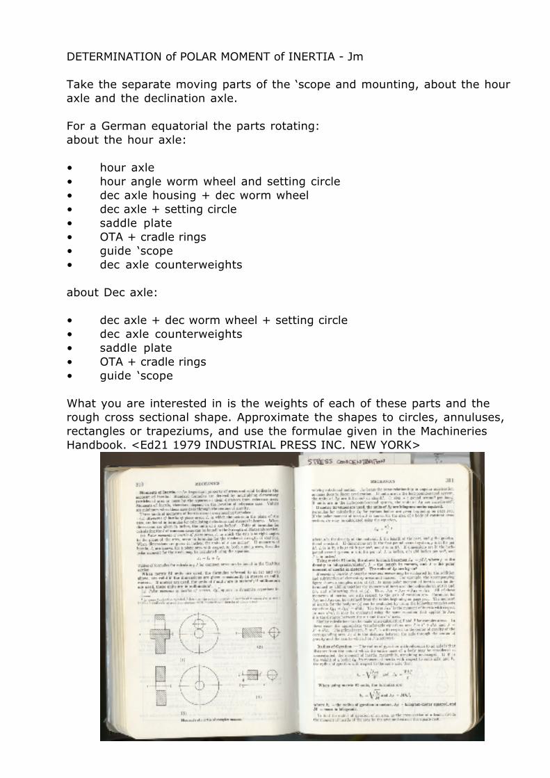
DETERMINATION of POLAR MOMENT of INERTIA - Jm Take the separate moving parts of the ‘scope and mounting, about the hour axle and the declination axle. For a German equatorial the parts rotating: about the hour axle: • hour axle • hour angle worm wheel and setting circle • dec axle housing + dec worm wheel • dec axle + setting circle • saddle plate • OTA + cradle rings • guide ‘scope • dec axle counterweights about Dec axle: • dec axle + dec worm wheel + setting circle • dec axle counterweights • saddle plate • OTA + cradle rings • guide ‘scope What you are interested in is the weights of each of these parts and the rough cross sectional shape. Approximate the shapes to circles, annuluses, rectangles or trapeziums, and use the formulae given in the Machineries Handbook. <Ed21 1979 INDUSTRIAL PRESS INC. NEW YORK>
Transcript
DETERMINATION of POLAR MOMENT of INERTIA - Jm
Take the separate moving parts of the ‘scope and mounting, about the hour axle and the declination axle.
For a German equatorial the parts rotating:about the hour axle:
• hour axle• hour angle worm wheel and setting circle• dec axle housing + dec worm wheel• dec axle + setting circle• saddle plate• OTA + cradle rings• guide ‘scope• dec axle counterweights
about Dec axle:
• dec axle + dec worm wheel + setting circle• dec axle counterweights• saddle plate• OTA + cradle rings• guide ‘scope
What you are interested in is the weights of each of these parts and the rough cross sectional shape. Approximate the shapes to circles, annuluses, rectangles or trapeziums, and use the formulae given in the Machineries Handbook. <Ed21 1979 INDUSTRIAL PRESS INC. NEW YORK>
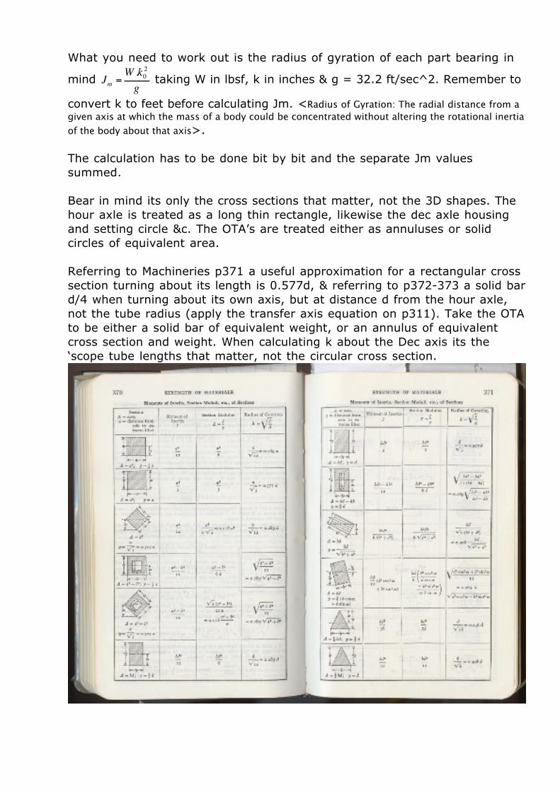
What you need to work out is the radius of gyration of each part bearing in
mind
€
Jm =W .k02
g taking W in lbsf, k in inches & g = 32.2 ft/sec^2. Remember to
convert k to feet before calculating Jm. <Radius of Gyration: The radial distance from a given axis at which the mass of a body could be concentrated without altering the rotational inertia of the body about that axis>. The calculation has to be done bit by bit and the separate Jm values summed.
Bear in mind its only the cross sections that matter, not the 3D shapes. The hour axle is treated as a long thin rectangle, likewise the dec axle housing and setting circle &c. The OTA’s are treated either as annuluses or solid circles of equivalent area.
Referring to Machineries p371 a useful approximation for a rectangular cross section turning about its length is 0.577d, & referring to p372-373 a solid bar d/4 when turning about its own axis, but at distance d from the hour axle, not the tube radius (apply the transfer axis equation on p311). Take the OTA to be either a solid bar of equivalent weight, or an annulus of equivalent cross section and weight. When calculating k about the Dec axis its the ‘scope tube lengths that matter, not the circular cross section.
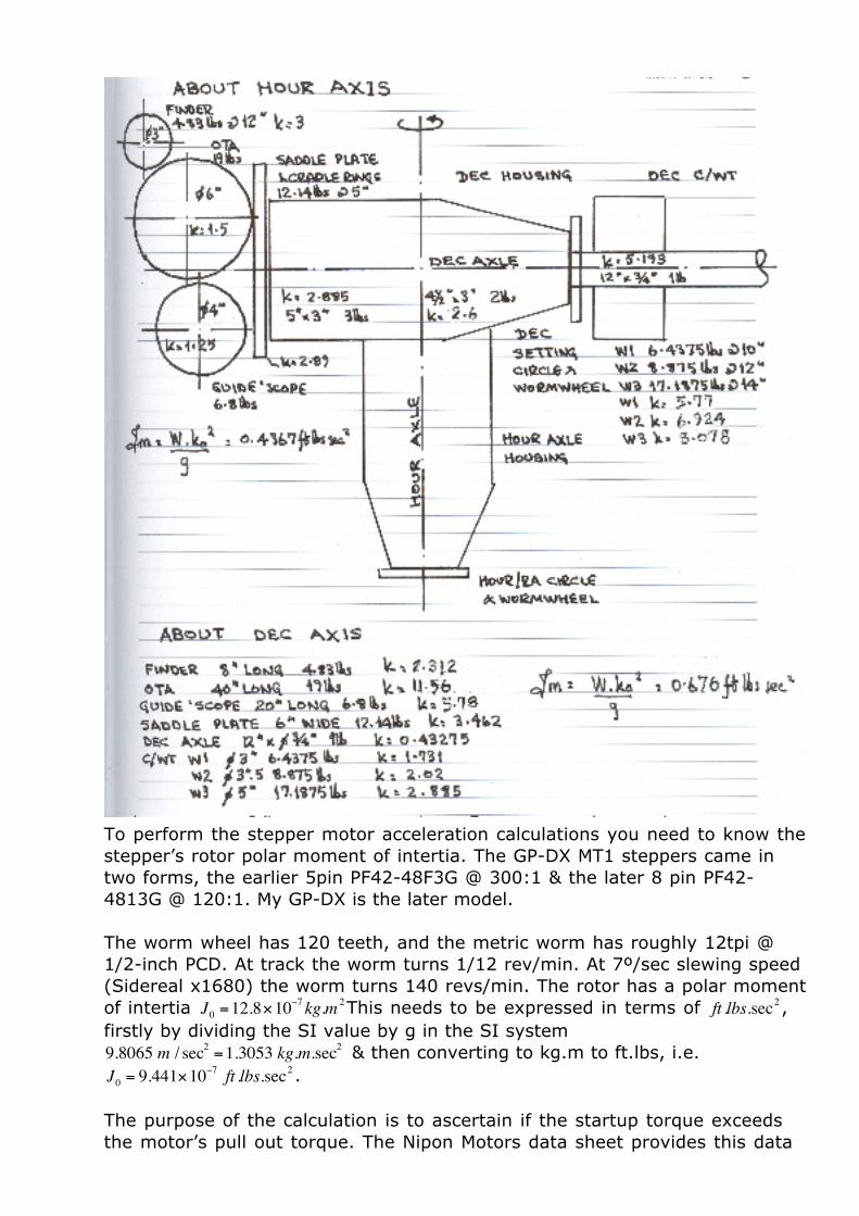
This is a sample Jm calculation for a Vixen GP-DX carrying a Vixen Sphinx saddle extension plate, a TEC140APO, a WO Megrez90, a Vixen 70S guide’scope used as a finder, and three counterweights. The calculation for the parts turning about the hour axis include the Dec axle housing split into two, making it a rectangular or a trapezium cross section turning about one end. When calculating Jm about the Dec axis, because the Dec axle housing is static, it is omitted.
The radius of gyration is worked out for each part and then the Jm value
calculated using
€
Jm =W .k02
g taking
€
g = 32.2 ft / sec2 , and the separate Jm values
summed.
It is admittedly simpler to use the SI system, but I have no sense of the rightness or wrongness of the result when using MKS units, so I stick to what I know, the old Imperial Foot-Pound-Second system.
Another useful approach to estimating k is to work out the cross sectional area and the position of the centre of gravity (cg), and then use the moments of inertia of plane areas formulae. For example the Dec axle turning about its own axis, k = 0.289 d where d is the shaft diameter), but when turning about the hour axis, k = 0.577 d (where d is the distance to the start of the shaft from the Dec housing). Once you have the Jm value for both axes, the slewing dynamics calculation can be made.
To perform the stepper motor acceleration calculations you need to know the stepper’s rotor polar moment of intertia. The GP-DX MT1 steppers came in two forms, the earlier 5pin PF42-48F3G @ 300:1 & the later 8 pin PF42-4813G @ 120:1. My GP-DX is the later model.
The worm wheel has 120 teeth, and the metric worm has roughly 12tpi @ 1/2-inch PCD. At track the worm turns 1/12 rev/min. At 7º/sec slewing speed (Sidereal x1680) the worm turns 140 revs/min. The rotor has a polar moment of intertia
€
J0 =12.8×10⁻⁷ kg.m 2This needs to be expressed in terms of
€
ft .lbs.sec2 , firstly by dividing the SI value by g in the SI system
€
9.8065 m / sec2 =1.3053 kg.m.sec2 & then converting to kg.m to ft.lbs, i.e.
€
J0 = 9.441×10⁻⁷ ft .lbs.sec2 .
The purpose of the calculation is to ascertain if the startup torque exceeds the motor’s pull out torque. The Nipon Motors data sheet provides this data


![AVENTURA BRICKELL CITY CENTRE DOWNTOWN DADELAND … · AVENTURA BRICKELL CITY CENTRE DOWNTOWN DADELAND MIAMI BEACH Casa de Campo Mexico City JM JM JM JM JM JM JM JM [GF] Gluten freE](https://static.documents.pub/doc/80x56/5f3c14c92cc2286cb9022d6e/aventura-brickell-city-centre-downtown-dadeland-aventura-brickell-city-centre-downtown.jpg)


