DETERMINATION OF STEERING WHEEL ANGLES DURING CAR ALIGNMENT BY IMAGE ANALYSIS METHODS M. Mueller, T. Voegtle * Institute of Photogrammetry and Remote Sensing (IPF), Karlsruhe Institute of Technology (KIT), Germany – {markus.mueller5, thomas.voegtle}@kit.edu Commission V, WG V/1 KEY WORDS: Image analysis, image matching, quality assessment, industrial application ABSTRACT: Optical systems for automatic visual inspections are of increasing importance in the field of automation in the industrial domain. A new application is the determination of steering wheel angles during wheel track setting of the final inspection of car manufacturing. The camera has to be positioned outside the car to avoid interruptions of the processes and therefore, oblique images of the steering wheel must be acquired. Three different approaches of computer vision are considered in this paper, i.e. a 2D shape-based matching (by means of a plane to plane rectification of the oblique images and detection of a shape model with a particular rotation), a 3D shape-based matching approach (by means of a series of different perspectives of the spatial shape of the steering wheel derived from a CAD design model) and a point-to-point matching (by means of the extraction of significant elements (e.g. multifunctional buttons) of a steering wheel and a pairwise connection of these points to straight lines). The HALCON system (HALCON, 2016) was used for all software developments and necessary adaptions. As reference a mechanical balance with an accuracy of 0.1° was used. The quality assessment was based on two different approaches, a laboratory test and a test during production process. In the laboratory a standard deviation of ±0.035° (2D shape-based matching), ±0.12° (3D approach) and ±0.029° (point-to-point matching) could be obtained. The field test of 291 measurements (27 cars with varying poses and angles of the steering wheel) results in a detection rate of 100% and ±0.48° (2D matching) and ±0.24° (point-to-point matching). Both methods also fulfil the request of real time processing (three measurements per second). * Corresponding author 1. INTRODUCTION In the industrial environment quality control has become an essential part of the production process. The aim of a 100% control in all stages can only be obtained by a comprehensive automation. Optical systems are of increasing importance in this wide-ranging field. Especially automatic visual inspections based on digital imagery allow contact-free real time measurements of high accuracy in dynamic production processes. Besides typical tasks like reading of labels, checks of completeness or the extraction of metric measures like length, distance, diameter etc. also more complex challenges can be met by image analysis. One of such new applications in this field is the determination of steering wheel angles during car alignment in the context of the final inspection of manufacturing. During wheel track setting the current steering wheel angle needs to be determined and subsequently aligned to a horizontal position (rotation angle = 0°). Until now this has been carried out by means of a mechanical steering wheel balance. In this research a steering wheel balance of manufacturer DSA (DSA, 2016) was used with an operation area of ±20°. This balance delivers an accuracy of 0.1° (Dürr, 2016a). Own investigations on the repeatability based on 100 measurements have confirmed an effective accuracy for small angles of approx. ±0.03° including the influences by slightly different manual positioning of the balance by an operator. Therefore, it is even better than the manufacturer’s accuracy value of 0.1° documented in the instructions. The requested accuracy for this application was defined by ±0.2°. In the absence of alternative measuring techniques this balance has been taken as reference. The camera system has the advantage of contact-free measurement where the error component introduced by the manually positioning of the balance can be excluded. The camera has to be positioned outside the car to avoid any interruption of the dynamic manufacturing process and therefore, oblique images of the steering wheel are acquired through the opened side window of the car. 2. RELATED WORK Many tasks in industrial environments can be solved with computer vision or machine vision systems (MVS). Image information supporting production lines or solving special tasks independently and thoroughly are getting more and more involved into the industrial processes of many manufacturers. Nowadays, tasks like completeness checks (Haniff et al., 2011), inspections (Molleda et al., 2013), (pre-)selections of construction elements (Rodrigues et al., 2012) or quality tests (Gunasekaran, 1996) are already fulfilled using the potential of robust machine vision systems operating in real time. The The International Archives of the Photogrammetry, Remote Sensing and Spatial Information Sciences, Volume XLI-B5, 2016 XXIII ISPRS Congress, 12–19 July 2016, Prague, Czech Republic This contribution has been peer-reviewed. doi:10.5194/isprsarchives-XLI-B5-77-2016 77
Transcript
DETERMINATION OF STEERING WHEEL ANGLES DURING CAR ALIGNMENT BY
IMAGE ANALYSIS METHODS
M. Mueller, T. Voegtle *
Institute of Photogrammetry and Remote Sensing (IPF), Karlsruhe Institute of Technology (KIT), Germany –
Optical systems for automatic visual inspections are of increasing importance in the field of automation in the industrial domain. A
new application is the determination of steering wheel angles during wheel track setting of the final inspection of car manufacturing.
The camera has to be positioned outside the car to avoid interruptions of the processes and therefore, oblique images of the steering
wheel must be acquired. Three different approaches of computer vision are considered in this paper, i.e. a 2D shape-based matching
(by means of a plane to plane rectification of the oblique images and detection of a shape model with a particular rotation), a 3D
shape-based matching approach (by means of a series of different perspectives of the spatial shape of the steering wheel derived from
a CAD design model) and a point-to-point matching (by means of the extraction of significant elements (e.g. multifunctional
buttons) of a steering wheel and a pairwise connection of these points to straight lines). The HALCON system (HALCON, 2016)
was used for all software developments and necessary adaptions. As reference a mechanical balance with an accuracy of 0.1° was
used. The quality assessment was based on two different approaches, a laboratory test and a test during production process. In the
laboratory a standard deviation of ±0.035° (2D shape-based matching), ±0.12° (3D approach) and ±0.029° (point-to-point matching)
could be obtained. The field test of 291 measurements (27 cars with varying poses and angles of the steering wheel) results in a
detection rate of 100% and ±0.48° (2D matching) and ±0.24° (point-to-point matching). Both methods also fulfil the request of real
time processing (three measurements per second).
* Corresponding author
1. INTRODUCTION
In the industrial environment quality control has become an
essential part of the production process. The aim of a 100%
control in all stages can only be obtained by a comprehensive
automation. Optical systems are of increasing importance in this
wide-ranging field. Especially automatic visual inspections
based on digital imagery allow contact-free real time
measurements of high accuracy in dynamic production
processes. Besides typical tasks like reading of labels, checks of
completeness or the extraction of metric measures like length,
distance, diameter etc. also more complex challenges can be met
by image analysis. One of such new applications in this field is
the determination of steering wheel angles during car alignment
in the context of the final inspection of manufacturing. During
wheel track setting the current steering wheel angle needs to be
determined and subsequently aligned to a horizontal position
(rotation angle = 0°). Until now this has been carried out by
means of a mechanical steering wheel balance. In this research a
steering wheel balance of manufacturer DSA (DSA, 2016) was
used with an operation area of ±20°. This balance delivers an
accuracy of 0.1° (Dürr, 2016a). Own investigations on the
repeatability based on 100 measurements have confirmed an
effective accuracy for small angles of approx. ±0.03° including
the influences by slightly different manual positioning of the
balance by an operator. Therefore, it is even better than the
manufacturer’s accuracy value of 0.1° documented in the
instructions. The requested accuracy for this application was
defined by ±0.2°. In the absence of alternative measuring
techniques this balance has been taken as reference. The camera
system has the advantage of contact-free measurement where
the error component introduced by the manually positioning of
the balance can be excluded. The camera has to be positioned
outside the car to avoid any interruption of the dynamic
manufacturing process and therefore, oblique images of the
steering wheel are acquired through the opened side window of
the car.
2. RELATED WORK
Many tasks in industrial environments can be solved with
computer vision or machine vision systems (MVS). Image
information supporting production lines or solving special tasks
independently and thoroughly are getting more and more
involved into the industrial processes of many manufacturers.
Nowadays, tasks like completeness checks (Haniff et al., 2011),
inspections (Molleda et al., 2013), (pre-)selections of
construction elements (Rodrigues et al., 2012) or quality tests
(Gunasekaran, 1996) are already fulfilled using the potential of
robust machine vision systems operating in real time. The
The International Archives of the Photogrammetry, Remote Sensing and Spatial Information Sciences, Volume XLI-B5, 2016 XXIII ISPRS Congress, 12–19 July 2016, Prague, Czech Republic
This contribution has been peer-reviewed. doi:10.5194/isprsarchives-XLI-B5-77-2016
77
required parameters are directly determined by the MVS and
then transferred for further processing or evaluation.
In this paper image analysis methods like shape-based matching
or image rectification are used (HALCON, 2015a). Shape-based
matching can be performed using two- or three-dimensional
approaches. 2D methods can be found in (Haniff et al., 2011),
(Xu et al., 2008) or (Fan et al., 2014) and are, in principle,
suitable to achieve sub-pixel accuracies. 3D approaches
determining the pose of an object like reported in (Ulrich et al.,
2009) or (Reinbacher et al., 2010) have advantages over 2D
methods but may lead to insufficient results according to real
time capability or accuracy for specific tasks. Cars need to pass
several alignment and initial operation processes before their
delivery. One of these alignment steps is the adjustment of the
chassis. During the setting of the front suspension the so-called
steering angle needs to be aligned to the front axle. Usually the
determination of this steering angle is carried out by means of a
mechanical steering wheel balance at leading automotive
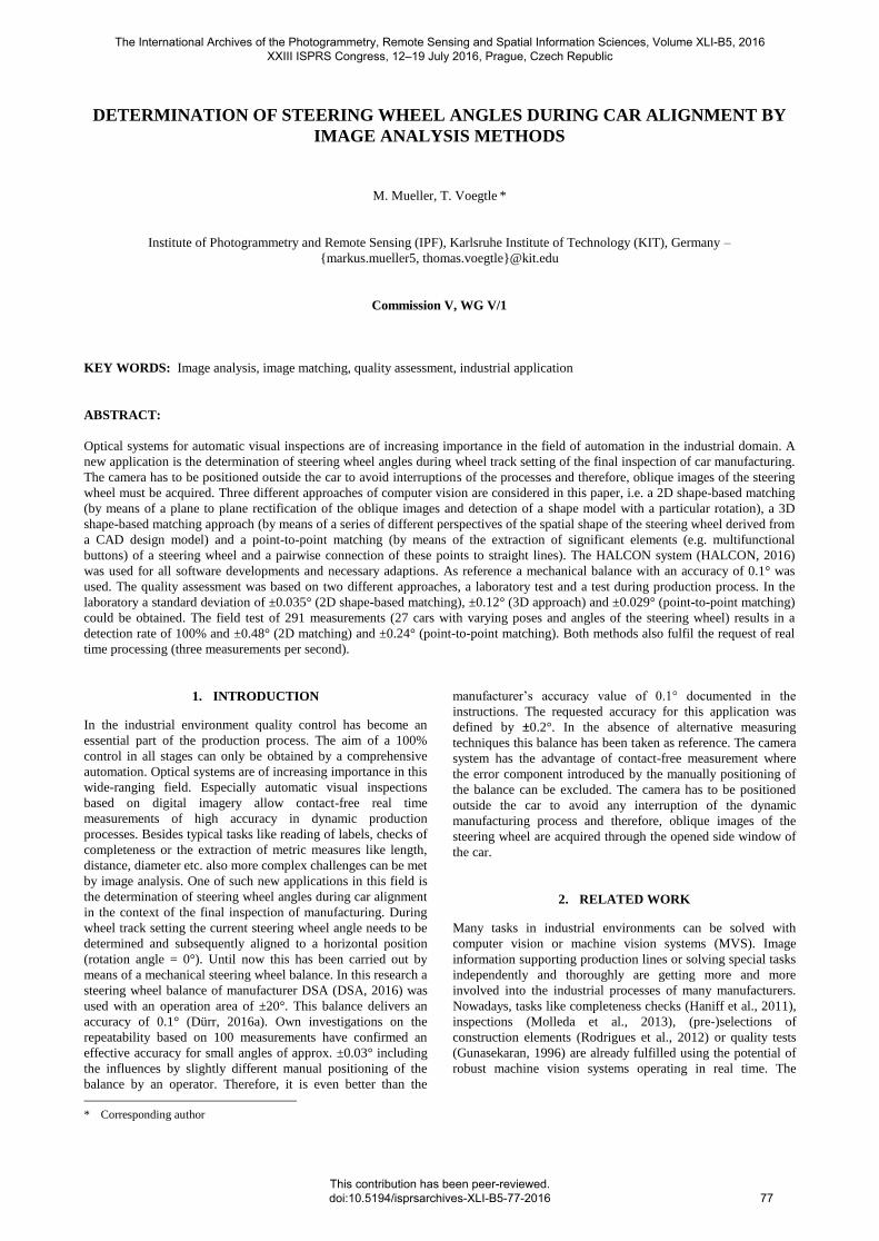
Figure 2. Tactile supporting point of the balance (DSA, 2016)
This balance gets attached on the steering wheel manually and
measures the current rotation angle of the steering wheel to the
horizontal. Steering wheel balances are getting distributed by
companies like Dürr AG (Dürr, 2016b) or DSA (DSA, 2016).
Duerr AG specifies its steering wheel balance named x-tronic
balance within a measuring accuracy of 0.1° (Dürr, 2016a).
Additional to this uncertainty, a dimensional tolerance has to be
added caused by slight deviations of the (tactile) attachment
(Figure 2).
3. DATA ACQUISITION AND PRE-PROCESSING
Compared to mechanical steering wheel balances camera based
vision systems have two main advantages. On the one hand
additional error influences by manual positioning can be
avoided due to contact-free measurements, on the other hand
the production process has not to be interrupted. For this vision
system the industrial camera UI-5370 (IDS, 2016) was applied.
Its features are sampled in Table 1.
Camera UI-5370 (IDS)
sensor type CMOS
size of sensor elements 5.5 μm
sensor size 2048 x 2048 pixels
radiometric resolution 12 bit/pixel
Table 1. Data of the industrial camera UI-5370
But as described above, the images of the steering wheel have to
be acquired from outside the car in an oblique viewing direction
through the opened side window. Common distances of approx.
2 m between steering wheel and camera can be realized which
results in pixel sizes of 0.10 to 0.15 mm on the object. First test
series have shown that the common illumination in real
production environments is normally not sufficient for this task.
Therefore, special lighting devices (e.g. ring-flashes) had to be
applied for a more uniform illumination and suitable image
contents. The real time requirements of the producer are defined
as three measurements per second.
As additional input data for the subsequent analysis of these
oblique images CAD models of the steering wheel types used in
this investigation are available. A fixed local coordinate system
has been defined for the steering wheels, where the x-axis is
horizontal, the y-axis is vertical and the z-axis is orthogonal to
these two axes (all related to the CAD construction plan).
The data acquisition has been carried out in two parts. On the
one hand several image series were generated in the laboratory
to develop and investigate different analysis approaches, on the
other hand images were recorded directly in the real production
environment to evaluate and improve suitable methods.
A first image series aimed to the determination of the repeat
accuracy. A steering wheel was (mechanically) fixed in its basic
pose and captured by 100 images resulting in a repeat accuracy
of ±0.0007° which has confirmed the extremely high quality
and the potential of our vision system (cf. repeat accuracy of the
mechanical steering wheel balance was ±0.03°). To generate
enough test material for development and evaluation of
appropriate analysis methods, different rotation angles
(mechanical balance as reference) and heights of the steering
wheel (for several types of cars the steering wheel can be moved
in height about 10 cm) have been captured by the camera in that
oblique viewing direction according to the perspective in the
production environment. In the domain of ±5° the rotation angle
has been incremented by steps of 1°, in the remaining domain of
±10° in increments of 2.5°. This acquisition constellation was
repeated for each of three different heights, the middle position
and +5 cm and -5 cm respectively. Therefore, 15 images have
been stored for each height position, which overall results in 45
images.
The International Archives of the Photogrammetry, Remote Sensing and Spatial Information Sciences, Volume XLI-B5, 2016 XXIII ISPRS Congress, 12–19 July 2016, Prague, Czech Republic
This contribution has been peer-reviewed. doi:10.5194/isprsarchives-XLI-B5-77-2016
78
In the real production process a first image series was acquired
with the camera mounted on an already existing pole (used for
other tasks). It could be recognized from the first results that the
pole was affected by concussions caused by the surrounding
machines. Therefore, a second image series was captured where
the camera was fixed to a static construction component of the
building. Additionally, a ring illumination around the camera
lens was used to guarantee uniform and constant lighting
conditions. This series comprises 291 images of 27 cars of two
similar steering wheel types, i.e. approx. 10 measurements per
car in a time period of 3 sec., which fulfils the real time request
of three measurements per second for this application.
4. METHODOLOGY
Three different approaches were developed to solve the problem
of a real time determination of steering angles during the car
alignment procedure in industrial environments. A calibrated
camera is a prerequisite for any of our three applied approaches.
Therefore, the machine vision system consists of a calibrated
camera, a computer and an illumination unit as a constant
configuration for all evaluations. In consequence, the methods
only differ in their software-based implementation.
4.1 2D Shape-based Matching
The first implementation was realized by a 2D shape-based
matching using HALCON routines (HALCON, 2015b). Unlike
other methods this technique does not operate with grey values
directly or correlation-based approaches but uses extracted
contours of an object to search for any number of instances of
this object in arbitrary images. In principle, the reference
contours can be extracted in an image containing the specified
object in a pre-defined rotation. These contours are stored in
different image pyramid levels and rotations in the reference
plane in a user-defined range (stepwise in small increments) as
reference. This is called a 2D shape-model. An object can be
searched using the provided shape-model with its rotations and
scales. An instance of an object can only be recognized if it
appears in the provided rotation- and scale-range, otherwise it
will not be detected. After a coarse detection of possible
instances fitting the quested shape, based on a modified
generalized Hough transform (Ulrich et al., 2003), a pose
refinement is performed. For our specific application we make
use of this 2D shape-based matching method using the
multifunctional buttons of the steering wheels as distinctive
marks serving as such a shape-model (cf. Figure 3).
Figure 3. Creating a shape-model from reference image. Left:
image containing a field of multifunctional buttons. Right:
extracted contours of created shape-model
Supposing an orthogonal view of the steering wheel the rotation
of an arbitrary element is equivalent to a rotation of the steering
wheel itself. Therefore, the rotation of the multifunctional
buttons can be used for the determination of the steering angle.
Due to oblique viewing directions through the side window an
orthogonal orientation of the camera to the steering wheel is not
realizable. Because of the resulting perspective distortions a
2D-rotation of the steering wheel (and its components) does not
correspond to its rotation in the image. To overcome this
problem a geometric rectification is applied, transforming an
oblique image into an orthogonal view by means of a defined
reference plane. Then the rotation of a component of the wheel
in the rectified image is equivalent to the requested rotation of
the steering wheel itself. However, for the absolute
determination of the rotation of a steering wheel, we make use
of a reference image showing a horizontal aligned steering
wheel (angle = 0°). The rotation of the extracted shape model in
that image will be used as initial value ΦRef. Then, in
subsequently acquired images we can compute the difference
between the current steering wheel rotation Φi in image i and
the reference rotation ΦRef to obtain the required current
steering wheel angle λi
λi = Φi – ΦRef (1)
4.2 3D Shape-based Matching
Another option for solving this task is given by a 3D shape-
based matching (HALCON, 2015c). This approach is able to
deliver a 3D pose of an object by means of a series of slightly
different views of the 3D CAD construction plan by a virtual
monocular camera (Ulrich et al., 2009). This series of virtual
images covers a user-defined range of possible viewing angles
around the main viewing direction as well as different distances
of the camera (both related to the subsequent application) in
small increments (Figure 4). Additionally, for each of these
camera poses a series of views with different rotation angles is
created as a basis for the further determination of the steering
angle. The total of all images is combined to a 3D shape model.
Figure 4. Several model views from different camera positions
and orientations in a user-specified area pointing to the origin of
the object (Ulrich et al., 2009)
Before the determination of the requested steering angle in the
production process can be started, a reference image of a
horizontal aligned steering wheel (by means of the mechanical
The International Archives of the Photogrammetry, Remote Sensing and Spatial Information Sciences, Volume XLI-B5, 2016 XXIII ISPRS Congress, 12–19 July 2016, Prague, Czech Republic
This contribution has been peer-reviewed. doi:10.5194/isprsarchives-XLI-B5-77-2016
79
balance) has to be acquired. Subsequently, in a current image an
edge extraction is carried out. These edges are compared to the
contours of the 3D shape model by a best fit procedure
(matching) to obtain the pose of the steering wheel related to
the camera coordinate system. Now, the steering angle can be
calculated by the difference to the reference data. Similar to the
2D approach explained above a pose refinement is processed
after the determination of the coarse view respectively coarse
pose.
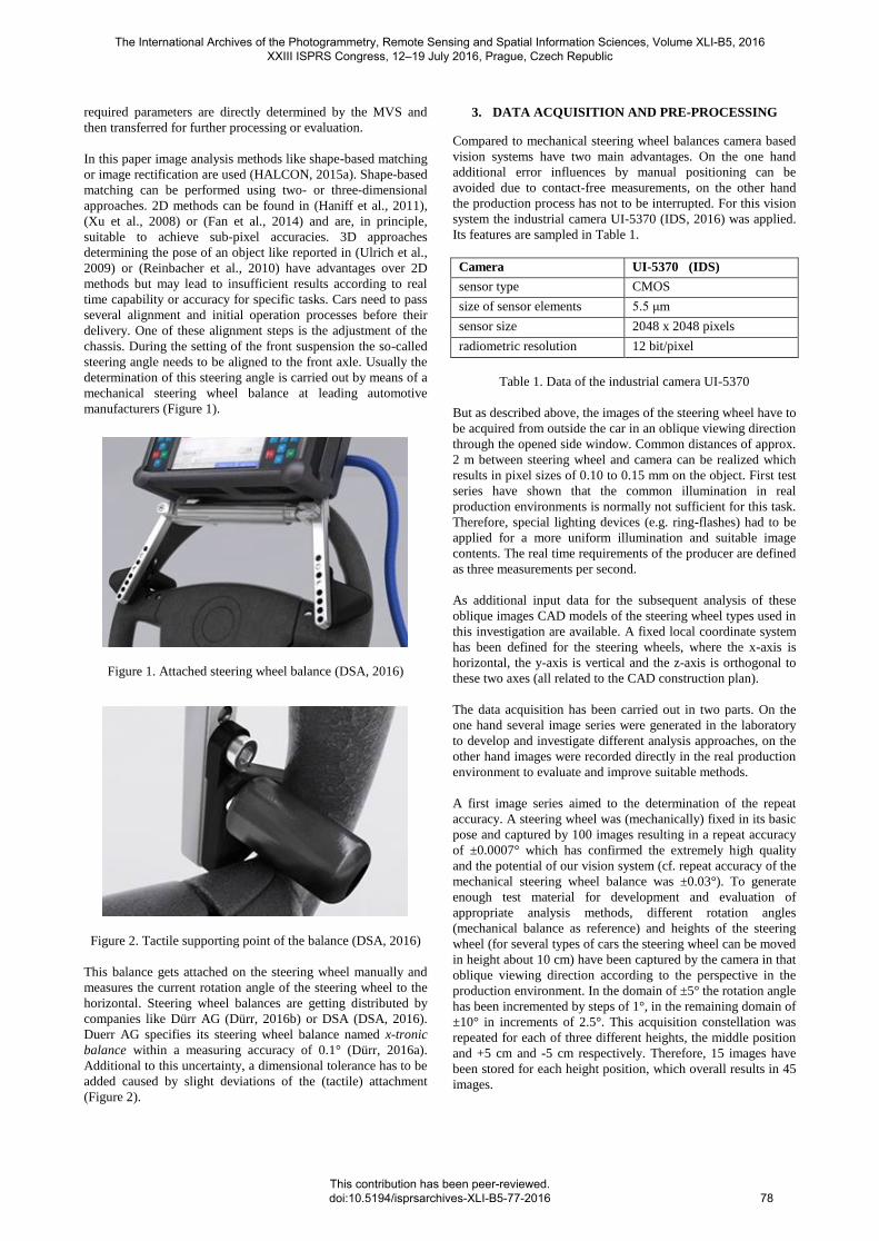
Complex CAD models containing a huge number of geometric
primitives may lead to insufficient processing times. Therefore,
these CAD models should be reduced to the main significant
and distinctive elements to guarantee real time processing.
Nevertheless, spatial expanded elements will lead to more
robust results concerning the determination of the rotational
angle. A suitable choice is the use of multifunctional buttons
spatially far apart (Figure 5).
Figure 5. Matching results of the CAD model (green)
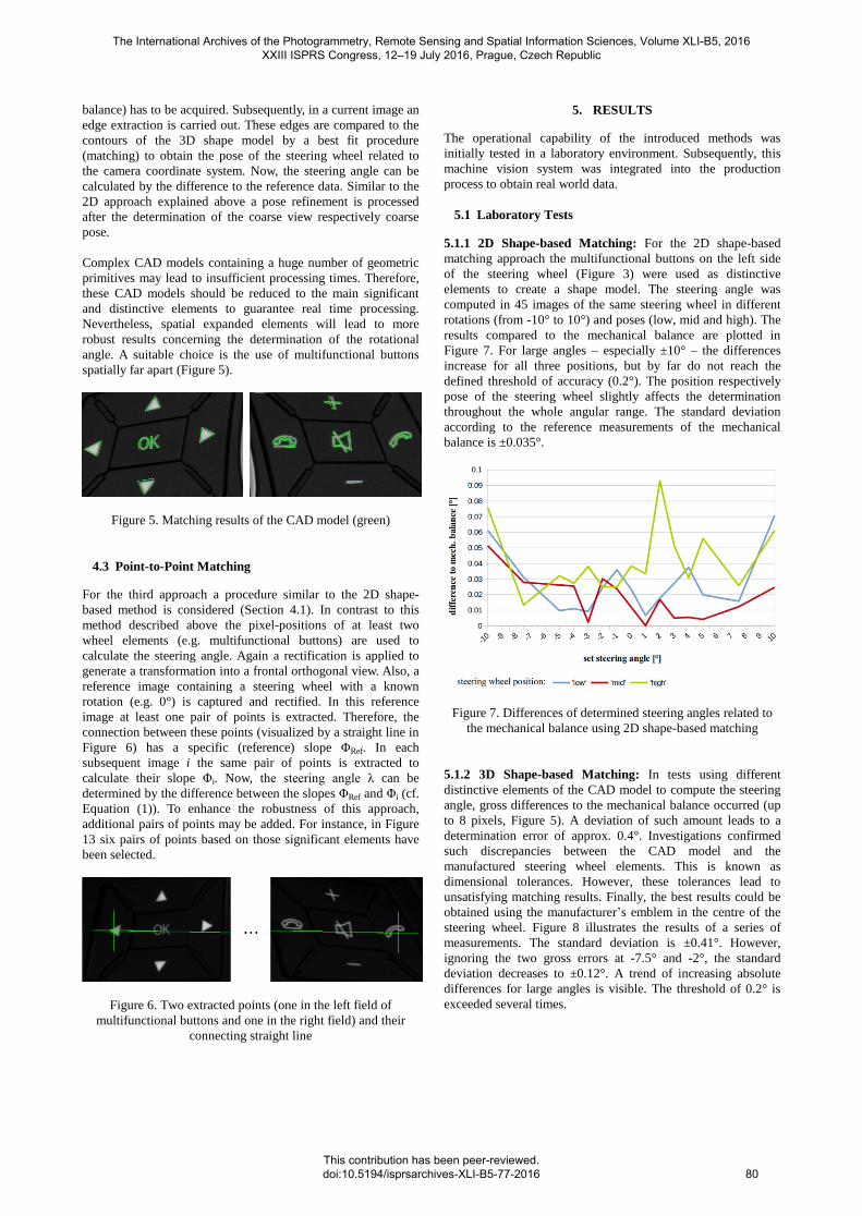
4.3 Point-to-Point Matching
For the third approach a procedure similar to the 2D shape-
based method is considered (Section 4.1). In contrast to this
method described above the pixel-positions of at least two
wheel elements (e.g. multifunctional buttons) are used to
calculate the steering angle. Again a rectification is applied to
generate a transformation into a frontal orthogonal view. Also, a
reference image containing a steering wheel with a known
rotation (e.g. 0°) is captured and rectified. In this reference
image at least one pair of points is extracted. Therefore, the
connection between these points (visualized by a straight line in
Figure 6) has a specific (reference) slope ΦRef. In each
subsequent image i the same pair of points is extracted to
calculate their slope Φi. Now, the steering angle λ can be
determined by the difference between the slopes ΦRef and Φi (cf.
Equation (1)). To enhance the robustness of this approach,
additional pairs of points may be added. For instance, in Figure
13 six pairs of points based on those significant elements have
been selected.
Figure 6. Two extracted points (one in the left field of
multifunctional buttons and one in the right field) and their
connecting straight line
5. RESULTS
The operational capability of the introduced methods was
initially tested in a laboratory environment. Subsequently, this
machine vision system was integrated into the production
process to obtain real world data.
5.1 Laboratory Tests
5.1.1 2D Shape-based Matching: For the 2D shape-based
matching approach the multifunctional buttons on the left side
of the steering wheel (Figure 3) were used as distinctive
elements to create a shape model. The steering angle was
computed in 45 images of the same steering wheel in different
rotations (from -10° to 10°) and poses (low, mid and high). The
results compared to the mechanical balance are plotted in
Figure 7. For large angles – especially ±10° – the differences
increase for all three positions, but by far do not reach the
defined threshold of accuracy (0.2°). The position respectively
pose of the steering wheel slightly affects the determination
throughout the whole angular range. The standard deviation
according to the reference measurements of the mechanical
balance is ±0.035°.
Figure 7. Differences of determined steering angles related to
the mechanical balance using 2D shape-based matching
5.1.2 3D Shape-based Matching: In tests using different
distinctive elements of the CAD model to compute the steering
angle, gross differences to the mechanical balance occurred (up
to 8 pixels, Figure 5). A deviation of such amount leads to a
determination error of approx. 0.4°. Investigations confirmed
such discrepancies between the CAD model and the
manufactured steering wheel elements. This is known as
dimensional tolerances. However, these tolerances lead to
unsatisfying matching results. Finally, the best results could be
obtained using the manufacturer’s emblem in the centre of the
steering wheel. Figure 8 illustrates the results of a series of
measurements. The standard deviation is ±0.41°. However,
ignoring the two gross errors at -7.5° and -2°, the standard
deviation decreases to ±0.12°. A trend of increasing absolute
differences for large angles is visible. The threshold of 0.2° is
exceeded several times.
The International Archives of the Photogrammetry, Remote Sensing and Spatial Information Sciences, Volume XLI-B5, 2016 XXIII ISPRS Congress, 12–19 July 2016, Prague, Czech Republic
This contribution has been peer-reviewed. doi:10.5194/isprsarchives-XLI-B5-77-2016
80
Figure 8. Differences of determined steering angles related to
the mechanical balance using 3D shape-based matching
5.1.3 Point-to-Point Matching: The point-to-point matching
was evaluated analogue to the 2D shape-based matching. The
pair of points consists of one element (button) from the left side
and one from the right side of the steering wheel as shown in
Figure 6. The steering angle was computed in 45 images
containing the same steering wheel in different rotations and
poses. The results compared to the mechanical balance are
shown in Figure 9. These are similar to those illustrated in
Figure 7. However, the overall accuracy is slightly better
resulting in a standard deviation of ±0.029°. The obtained
values do not exceed 0.1° and lie far below the threshold of
0.2°.
Figure 9. Differences of determined steering angles related to
the mechanical balance using point-to-point matching
5.2 Field Tests
To evaluate the approaches using real data from industrial
environment, the machine vision system was integrated into the
production process. A reference image (steering angle = 0°) and
the steering wheels pose definition need to be determined once
after the camera and all parts of the machine vision system are
installed at the production site. Hence the 3D matching did not
deliver sufficient results – even more gross errors occurred – it
was excluded in the further analysis.
To confirm the sensitivity of such camera systems, Figure 10
shows how mechanical influences during the production
process affect the measurements of the vision system. At the
beginning the camera was mounted at a relatively thin pole
which tended to vibrations caused by concussions of the
surrounding machines. After a stop of the machines the camera
(and therefore the measurements) stabilizes beyond number 42
(Figure 10). Thereafter the camera was positioned on a static
pole without physical connection to the production platform.
For this reason, further problems had been avoided.
Figure 10. Differences of optical and mechanical determined
steering angles. Up to measurement 42 (vertical line) the effect
of concussions caused by the production environment is clearly
visible. After measurement 42, the camera was stabilized.
5.2.1 2D Shape-based Matching: The results of the 2D
approach are visualized in Figure 11. 291 measurements
including 27 different vehicles are plotted in the histogram of
the obtained differences to the mechanical steering wheel
balance. The red line indicates the accumulated differences.
Only 21,4% of the measurements lie beneath the threshold of
0.2°. A wide variation of differences is clearly visible. The
detection rate is 100%, i.e. for each image the distinctive
elements could be automatically recognized and the steering
angle could be calculated. The standard deviation for the plotted
differences is ±0.48°.
Figure 11. Histogram of the differences between the optical 2D
shape-based and the mechanical measurement method
5.2.2 Point-to-Point Matching: The point-to-point approach
was analyzed based on the identical image series of 27 cars.
Here 261 measurements were carried out. The difference of 30
measurements to the shape-based method results from partial
occlusions, hence the point-to-point matching uses the left and
the right field of multifunctional buttons which both must be
visible in the same image. These occlusions are caused by the
human operator at the beginning of a series of functional checks
during the car alignment. However, multiple determinations of
the steering angle could be obtained for each car. Figure 12
visualizes the corresponding histogram for the point-to-point
matching results, again calculated by the differences to the
mechanical balance. These differences obtained by the point-to-
point matching show significantly more small values compared
to the 2D shape-based matching. This leads to a better accuracy
and therefore to a standard deviation of ±0.24°. Furthermore,
61.5% of the differences lie below the limit of 0.2° and even
80.4% do not exceed the value of 0.25°.
The International Archives of the Photogrammetry, Remote Sensing and Spatial Information Sciences, Volume XLI-B5, 2016 XXIII ISPRS Congress, 12–19 July 2016, Prague, Czech Republic
This contribution has been peer-reviewed. doi:10.5194/isprsarchives-XLI-B5-77-2016
81
Figure 12. Histogram of the differences between the optical
point-to-point and the mechanical measurement method
5.3 Real Time Capability
To verify the real time capability of the applied approaches
Table 2 shows the processing time for the determination of the
steering angle of ten subsequent measurements in production
environment. The time for image acquisition is included and
took approximately 106 msec per image. As can be seen clearly
the 2D method (144 msec) and the point-to-point approach (136
msec) reach real time capability. The 3D shape-based matching
(348 msec) exceeds the threshold slightly. However, by
decreasing the search space of the 3D approach, a faster
computation than presented in Table 2 could be obtained.
Nevertheless, according to the insufficient accuracies of the 3D
shape-based matching an optimization was not intended.
No. 2D shape-based
[msec]
3D shape-based
[msec]
point-to-point
[msec]
1 145 400 142
2 144 377 138
3 145 362 137
4 141 298 133
5 142 318 134
6 142 323 133
7 143 337 134
8 144 346 135
9 145 356 136
10 146 362 136
average 144 348 136
Table 2. Overview of total processing times of the introduced
methods including the time for image acquisition (106 msec)
6. DISCUSSION
For determination of all results presented in the preceding
chapter a mechanical balance was used as reference. Therefore,
it has to be taken into account that those balances have also a
certain (limited) accuracy, i.e. the differences between the
steering wheel angles extracted by the computer vision system
and the mechanical balance contain also a component caused by
the balance itself. This should be regarded for the assessment of
the results, especially when taking into account the high interior
measurement accuracy of the computer vision system confirmed
during the laboratory research.
Comparing the results of the laboratory tests of the three
approaches it is obvious that the 3D shape-based matching has
proved to be not sufficient for this specific task concerning
robustness (gross errors occurred) and accuracy (±0.12°). The
reasons can be found in the (limited) manufacturing accuracy of
the multifunctional buttons (given by ±0.2 mm) which prevents
an optimal fit of the CAD construction plan. The 2D shape-
based matching has proved a high robustness, i.e. a detection
rate of 100% and an accuracy of ±0.035° due to several larger
deviations. Similar results could be obtained by the point-to-
point matching. The high robustness of 100% and the accuracy
of the steering angle of ±0.029° are comparable to the 2D
method which confirms the high quality potential of these
image analysis approaches.
Even if defined and stable conditions for image acquisition
could be realized in both environments (stable camera
mounting, constant and uniform lighting conditions etc.) the
results of the laboratory tests are significantly better compared
to the field tests. In the laboratory for all investigations only one
identical steering wheel was used. Therefore, positional
deviations of the distinctive elements (multifunctional buttons)
could be avoided. In contrast, in production environment 27
different cars have been analyzed with the same steering wheel
type but certain manufacturing tolerances (±0.2 mm). These
slightly different steering wheel geometries lead to uncertainties
in the determination of the steering angle. Another reason is the
new manual attachment of the balance for each car. So the
accuracy of the 2D shape-based matching is significantly
reduced to ±0.48° and for the point-to-point matching to
±0.24°, even if the determination of the position of the extracted
features (multifunctional buttons) is carried out in a high
accuracy (sub-pixel domain). For the 2D shape-based matching
the entire field of these multifunctional buttons (on the left or
right side of the steering wheel) is used as pattern which leads
to a reduced fitting accuracy due to these tolerances. For the
point-to-point matching individual buttons on both sides are
extracted separately resulting in larger distances and therefore,
in more stable baselines and finally in smaller deviations of the
determined steering angle.
Another main aspect of data acquisition in real production
environments concerns the extremely stable mounting of the
camera. It could be verified that the computer vision system has
a high sensitivity due to exterior mechanical influences. For
instance, the relatively thin metal pole used as mounting device
in first field tests tended to vibrations (caused by concussions of
other machines in the manufacturing hall) introducing effects
significantly larger than the measurement accuracy (cf. Figure
10, up to measurement 42). After termination of these exterior
influences, realistic values with slight deviations could be
obtained.
Concerning the processing time, the point-to-point matching is
the fastest method (30 msec), followed by the 2D shape-based
matching (38 msec) and the 3D shape-based matching (242
msec). Additionally, the time for image acquisition of approx.
106 msec has to be taken into account. In total, the 3D shape-
based matching is the only method, which does not fulfil the
requirement of real time processing, i.e. 3 measurements per
second (= 333 msec), whereas both described 2D approaches
meet the real time condition.
Overall, the point-to-point matching has proved to be the fastest
and most accurate method which approximately reaches the
defined accuracy threshold of ±0.2° in the production
The International Archives of the Photogrammetry, Remote Sensing and Spatial Information Sciences, Volume XLI-B5, 2016 XXIII ISPRS Congress, 12–19 July 2016, Prague, Czech Republic
This contribution has been peer-reviewed. doi:10.5194/isprsarchives-XLI-B5-77-2016
82
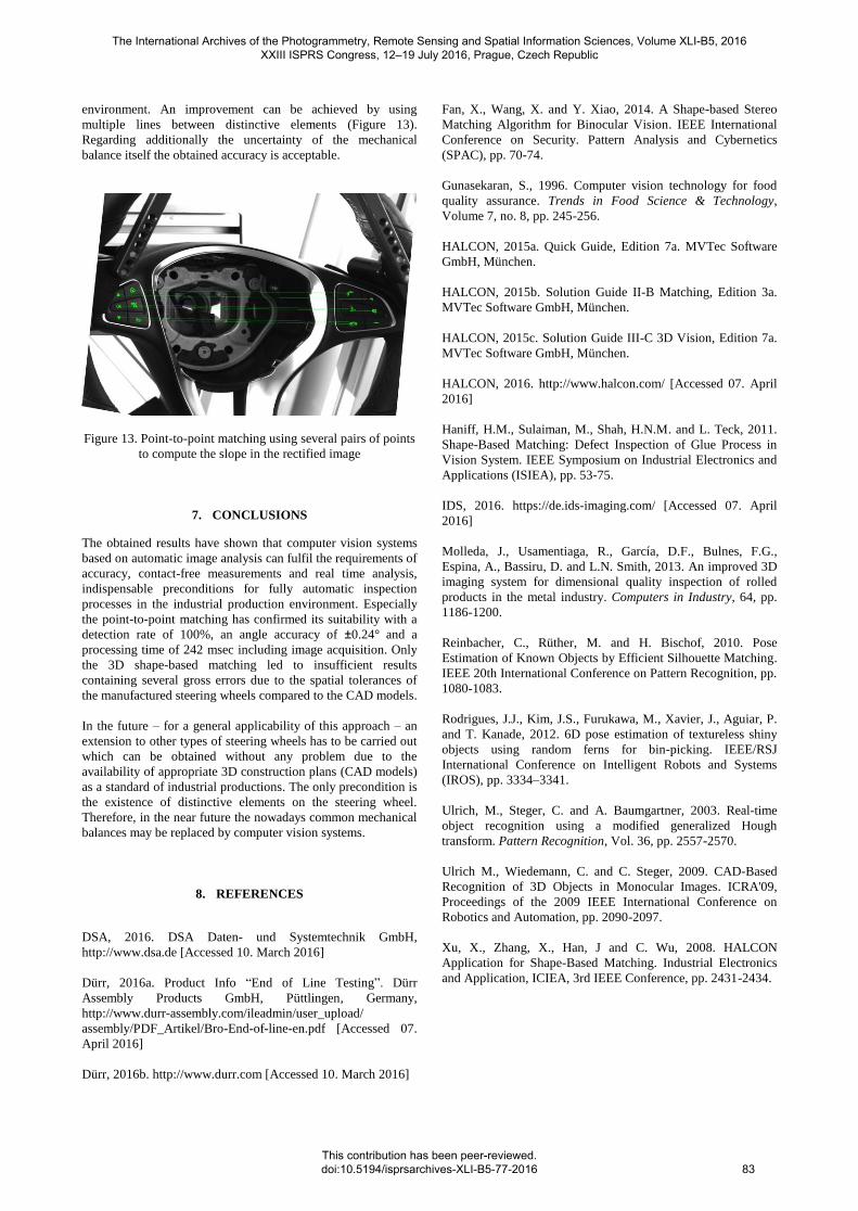
environment. An improvement can be achieved by using
multiple lines between distinctive elements (Figure 13).
Regarding additionally the uncertainty of the mechanical
balance itself the obtained accuracy is acceptable.
Figure 13. Point-to-point matching using several pairs of points
to compute the slope in the rectified image
7. CONCLUSIONS
The obtained results have shown that computer vision systems
based on automatic image analysis can fulfil the requirements of
accuracy, contact-free measurements and real time analysis,
indispensable preconditions for fully automatic inspection
processes in the industrial production environment. Especially
the point-to-point matching has confirmed its suitability with a
detection rate of 100%, an angle accuracy of ±0.24° and a
processing time of 242 msec including image acquisition. Only
the 3D shape-based matching led to insufficient results
containing several gross errors due to the spatial tolerances of
the manufactured steering wheels compared to the CAD models.
In the future – for a general applicability of this approach – an
extension to other types of steering wheels has to be carried out
which can be obtained without any problem due to the
availability of appropriate 3D construction plans (CAD models)
as a standard of industrial productions. The only precondition is
the existence of distinctive elements on the steering wheel.
Therefore, in the near future the nowadays common mechanical
balances may be replaced by computer vision systems.
8. REFERENCES
DSA, 2016. DSA Daten- und Systemtechnik GmbH,
http://www.dsa.de [Accessed 10. March 2016]
Dürr, 2016a. Product Info “End of Line Testing”. Dürr
HALCON, 2015c. Solution Guide III-C 3D Vision, Edition 7a.
MVTec Software GmbH, München.
HALCON, 2016. http://www.halcon.com/ [Accessed 07. April
2016]
Haniff, H.M., Sulaiman, M., Shah, H.N.M. and L. Teck, 2011.
Shape-Based Matching: Defect Inspection of Glue Process in
Vision System. IEEE Symposium on Industrial Electronics and
Applications (ISIEA), pp. 53-75.
IDS, 2016. https://de.ids-imaging.com/ [Accessed 07. April
2016]
Molleda, J., Usamentiaga, R., García, D.F., Bulnes, F.G.,
Espina, A., Bassiru, D. and L.N. Smith, 2013. An improved 3D
imaging system for dimensional quality inspection of rolled
products in the metal industry. Computers in Industry, 64, pp.
1186-1200.
Reinbacher, C., Rüther, M. and H. Bischof, 2010. Pose
Estimation of Known Objects by Efficient Silhouette Matching.
IEEE 20th International Conference on Pattern Recognition, pp.
1080-1083.
Rodrigues, J.J., Kim, J.S., Furukawa, M., Xavier, J., Aguiar, P.
and T. Kanade, 2012. 6D pose estimation of textureless shiny
objects using random ferns for bin-picking. IEEE/RSJ
International Conference on Intelligent Robots and Systems
(IROS), pp. 3334–3341.
Ulrich, M., Steger, C. and A. Baumgartner, 2003. Real-time
object recognition using a modified generalized Hough
transform. Pattern Recognition, Vol. 36, pp. 2557-2570.
Ulrich M., Wiedemann, C. and C. Steger, 2009. CAD-Based
Recognition of 3D Objects in Monocular Images. ICRA'09,
Proceedings of the 2009 IEEE International Conference on
Robotics and Automation, pp. 2090-2097.
Xu, X., Zhang, X., Han, J and C. Wu, 2008. HALCON
Application for Shape-Based Matching. Industrial Electronics
and Application, ICIEA, 3rd IEEE Conference, pp. 2431-2434.
The International Archives of the Photogrammetry, Remote Sensing and Spatial Information Sciences, Volume XLI-B5, 2016 XXIII ISPRS Congress, 12–19 July 2016, Prague, Czech Republic
This contribution has been peer-reviewed. doi:10.5194/isprsarchives-XLI-B5-77-2016


![arXiv:1803.03758v2 [cs.RO] 13 Apr 2020Fig.3: Ackerman Steering Geometry (left) and Side-slip Angles (left) In Fig. (3), the Ackerman steering geometry is depicted on the right. The](https://static.documents.pub/doc/80x56/60727960a46e7d213b15233d/arxiv180303758v2-csro-13-apr-2020-fig3-ackerman-steering-geometry-left.jpg)


