Welf-Guntram Drossel Fraunhofer Institute for Machine Tools and Forming Technology IWU, Reichenhainer Strasse 88, Chemnitz 09126, Germany e-mail: [email protected]Norbert Pierschel 1 Technische Universit € at Chemnitz, Professorship for Machine Tools and Forming Technologies, Strasse der Nationen 62, Chemnitz 09107, Germany e-mail: [email protected]Alexander Paul Fraunhofer Institute for Machine Tools and Forming Technology IWU, Reichenhainer Strasse 88, Chemnitz 09126, Germany e-mail: [email protected]Klaus Katzfuß Hochdruck- und Sonderhydraulik Leipzig GmbH, Edisonstrasse 12, Schkeuditz 04435, Germany e-mail: [email protected]Rico Demuth Fraunhofer Institute for Machine Tools and Forming Technology IWU, Reichenhainer Strasse 88, Chemnitz 09126, Germany e-mail: [email protected]Determination of the Active Medium Temperature in Media Based Press Hardening Processes Safety, lightweight design, and reduction of emissions are terms which are key issues in modern vehicle construction. These challenges can be met by new lightweight design strategies, e.g., by using lightweight materials and high-strength steels as well as innova- tive forming technologies such as media based press hardening (MBPH). MBPH as a sub-production technique of hydroforming is a tempered internal high-pressure forming process of closed profiles, which this article is about, or sheet metals by gaseous media. Due to the high process requirements (internal pressure up to 70 MPa and temperatures up to 1000 C), it has not been possible to measure the temperature curve of the active medium in a reliable way until now. The aim of the research project described in this article was to develop an innovative measuring instrument to determine the gas temperature curve with a measuring frequency of at least 1 Hz. Analytical and numerical calculations have indicated that the active medium has a significant influence on the ther- modynamic of the forming process. The finite element analysis (FEA) of the heat flow dur- ing the forming process has indicated that the influence of the gas on the cooling process of the work piece is about 15% of the total influence of the tool. Consequently, the active medium in media based press hardening processes is an important thermal influencing factor. Experiments have confirmed that it is possible to determine the calculated curve of the gas temperature and maximum temperatures of the active media up to 500 C. The findings of these studies make a significant contribution to identifying and analyzing the complete temperature balance in tempered active media based forming processes. [DOI: 10.1115/1.4025812] 1 Introduction and Motivation The growing global trade and relentless striving for increasing numbers of persons to elevate their mobility juxtaposed with increasing environmental pollution and the limitations set to global deposits of raw materials all point to the necessity of using our transport system as efficiently as possible. One way to boost efficiency that is gaining importance is building lightweight com- ponents and assemblies for highly dynamic masses. For instance, there is the option of building lightweight materials where the original material is replaced with a material with better mechani- cal properties at a lower level of density such as high-strength steels, aluminum, titanium, or plastics. The idea of lightweight design is better adapting the component part geometry to the load situation, which can save material and reduce weight. According to G€ oschel [1], the established production processes unfortunately are increasingly running up against their limitations in terms of implementing the resulting specifications for geometry and material. One alternative is the forming processes for profiles based on active medium. A case in point is hydroforming closed profiles that has proven to be advantageous in manufacturing com- plex connected geometries because the component parts produced in this way allow an excellent ratio between the lightweight potential and mechanical stability under load, as described in Refs. [2,3]. Referring to Karbasian and Tekkaya [4], forming at temperatures above the recrystallization temperature, (which is also called hot forming) has won out when processing high- strength steel materials and difficult-to-form lightweight metals such as titanium and magnesium for preventing a high level of process forces and extending the formability. The work piece material is not only subjected to a change in its shape but also microstructural changes which make it possible to achieve a clear increase in hardness and strength [5]. Figure 1 shows an example of the process-diagram of MBPH with the appropriate steps in the process. After heating the tube, it is inserted into the tool. When the tool is closed, the sealing punches are moved to the sealing position. By building up the pressure the profile forming and cooling starts, in particular at the contact points between the part and the tool. After a defined cooling period the completely formed component part is taken out of the tool and put to the following steps in processing. According to Neugebauer et al. [6], with MBPH significantly reduced process times compared to cold hydroforming can be realized. The application of this process is not only limited to closed profiles because tempered forming by means of gas is also used when forming sheet metals, hydroforming of blanks. In press hardening processes in general, the most common used steels are manganese-boron steels like 22MnB5. Due to its for martensitic transformation required minimum cooling rate of 27 K/s this steel needs a cooling in a tool or in a good heat transferring medium like water or oil. For reaching a martensitic transformation at lower cooling rates so called air hardenable steels with a higher content of manganese and boron (e.g., LH V R 800) are also used in series production. Another process where both temperature and 1 Corresponding author. Manuscript received February 26, 2013; final manuscript received October 23, 2013; published online February 5, 2014. Assoc. Editor: Gracious Ngaile. Journal of Manufacturing Science and Engineering APRIL 2014, Vol. 136 / 021013-1 Copyright V C 2014 by ASME Downloaded From: http://asmedigitalcollection.asme.org/ on 05/04/2014 Terms of Use: http://asme.org/terms
Transcript
Welf-Guntram DrosselFraunhofer Institute for Machine Tools
Determination of the ActiveMedium Temperaturein Media Based PressHardening ProcessesSafety, lightweight design, and reduction of emissions are terms which are key issues inmodern vehicle construction. These challenges can be met by new lightweight designstrategies, e.g., by using lightweight materials and high-strength steels as well as innova-tive forming technologies such as media based press hardening (MBPH). MBPH as asub-production technique of hydroforming is a tempered internal high-pressure formingprocess of closed profiles, which this article is about, or sheet metals by gaseous media.Due to the high process requirements (internal pressure up to 70 MPa and temperaturesup to 1000 �C), it has not been possible to measure the temperature curve of the activemedium in a reliable way until now. The aim of the research project described inthis article was to develop an innovative measuring instrument to determine the gastemperature curve with a measuring frequency of at least 1 Hz. Analytical and numericalcalculations have indicated that the active medium has a significant influence on the ther-modynamic of the forming process. The finite element analysis (FEA) of the heat flow dur-ing the forming process has indicated that the influence of the gas on the cooling processof the work piece is about 15% of the total influence of the tool. Consequently, the activemedium in media based press hardening processes is an important thermal influencingfactor. Experiments have confirmed that it is possible to determine the calculated curveof the gas temperature and maximum temperatures of the active media up to 500 �C. Thefindings of these studies make a significant contribution to identifying and analyzing thecomplete temperature balance in tempered active media based forming processes.[DOI: 10.1115/1.4025812]
1 Introduction and Motivation
The growing global trade and relentless striving for increasingnumbers of persons to elevate their mobility juxtaposed withincreasing environmental pollution and the limitations set toglobal deposits of raw materials all point to the necessity of usingour transport system as efficiently as possible. One way to boostefficiency that is gaining importance is building lightweight com-ponents and assemblies for highly dynamic masses. For instance,there is the option of building lightweight materials where theoriginal material is replaced with a material with better mechani-cal properties at a lower level of density such as high-strengthsteels, aluminum, titanium, or plastics. The idea of lightweightdesign is better adapting the component part geometry to the loadsituation, which can save material and reduce weight.
According to G€oschel [1], the established production processesunfortunately are increasingly running up against their limitationsin terms of implementing the resulting specifications for geometryand material. One alternative is the forming processes for profilesbased on active medium. A case in point is hydroforming closedprofiles that has proven to be advantageous in manufacturing com-plex connected geometries because the component parts producedin this way allow an excellent ratio between the lightweightpotential and mechanical stability under load, as described inRefs. [2,3]. Referring to Karbasian and Tekkaya [4], forming at
temperatures above the recrystallization temperature, (which isalso called hot forming) has won out when processing high-strength steel materials and difficult-to-form lightweight metalssuch as titanium and magnesium for preventing a high level ofprocess forces and extending the formability.
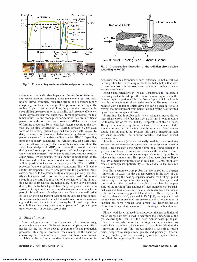
The work piece material is not only subjected to a change in itsshape but also microstructural changes which make it possible toachieve a clear increase in hardness and strength [5]. Figure 1shows an example of the process-diagram of MBPH with theappropriate steps in the process. After heating the tube, it isinserted into the tool. When the tool is closed, the sealing punchesare moved to the sealing position. By building up the pressure theprofile forming and cooling starts, in particular at the contactpoints between the part and the tool. After a defined coolingperiod the completely formed component part is taken out of thetool and put to the following steps in processing. According toNeugebauer et al. [6], with MBPH significantly reduced processtimes compared to cold hydroforming can be realized.
The application of this process is not only limited to closedprofiles because tempered forming by means of gas is also usedwhen forming sheet metals, hydroforming of blanks. In presshardening processes in general, the most common used steels aremanganese-boron steels like 22MnB5. Due to its for martensitictransformation required minimum cooling rate of 27 K/s this steelneeds a cooling in a tool or in a good heat transferring mediumlike water or oil. For reaching a martensitic transformation atlower cooling rates so called air hardenable steels with a highercontent of manganese and boron (e.g., LH
VR
800) are also used inseries production. Another process where both temperature and
1Corresponding author.Manuscript received February 26, 2013; final manuscript received October 23,
2013; published online February 5, 2014. Assoc. Editor: Gracious Ngaile.
Journal of Manufacturing Science and Engineering APRIL 2014, Vol. 136 / 021013-1Copyright VC 2014 by ASME
Downloaded From: http://asmedigitalcollection.asme.org/ on 05/04/2014 Terms of Use: http://asme.org/terms
strain rate have a decisive impact on the results of forming issuperplastic forming. Referring to Neugebauer et al. [6], this tech-nology allows extremely high true strain, and therefore highlycomplex geometries. Knowledge of the processes occurring in thetool-work piece system is deciding in production processes forstreamlining processes in terms of quality and resource efficiency.In analogy to conventional sheet metal forming processes, the tooltemperature TWZ and work piece temperature TWS are significantparameters with hot metal gas forming (HMGF) for the layoutof forming processes. Some other key factors specific to the pro-cess are the time dependence of internal pressure pi, the axialforce of the sealing punch Faxial, and the pusher path xpusher. Todate, there have not been any reliable measuring data on the tem-perature curve of the active medium during HMGF dependingupon the boundary conditions (tool temperature, tube wall thick-ness, and internal pressure). The aim of this paper is to extend thestate of knowledge with MBPH in terms of the thermal processesduring the forming process. This paper will include preliminaryanalytical and numerical observations and carry out and evaluateexperimental investigations. With a better understanding of thefluid flow and the temperature conditions of the active medium itwill be possible to increase the accuracy of the FEA of MBPHprocesses by more realistic boundary conditions. This will lead toshorter development time of new parts and the production proc-esses as well as to the producibility of complex parts e.g., by iden-tifying hot spots leading to lower cooling rates and to decreasedstrength of the part. The first step of a verification of the simula-tion results is measuring the temperature of the active mediumduring the media based press hardening. At present there is nosystem existing to reliable measure this temperature curve why onpart of this work was to develop such one. Beyond the verificationof the FEA the measurement system can be used for process mon-itoring and quality control in all hot metal gas forming processes,e.g., a detection of cracks while forming by a loss of temperatureor an indirect measuring of the part temperature for optimal cycletimes especially for complex geometries.
2 State of the Art
Tempered gaseous active media are used for manufacturingproducts in many areas of industry. An even temperature profile isneeded for the gas to be able to guarantee efficient productionprocesses. This implies precision measurement as the basis forcontrolling. It is state-of-the-art today that there is no systemavailable on the market or described in the technical literature for
measuring the gas temperature with reference to hot metal gasforming. Therefore, measuring methods are listed below that haveproven their worth in various areas such as automobiles, powerstations or refineries.
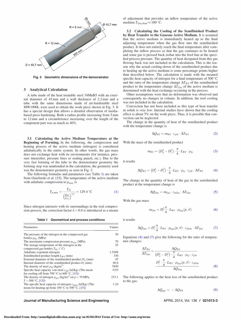
Irrgang and Michalowsky [7] and L€onnermark [8] describe ameasuring system based upon the use of thermocouples where thethermocouple is positioned in the flow of gas, which is how itrecords the temperature of the active medium. The sensor is sur-rounded with a radiation shield device as can be seen in Fig. 2 toprevent the measurement from being falsified by the heat radiatedby surrounding component parts.
Something that is problematic when using thermocouples ormeasuring sensors is the fact that they are designed not to measurethe temperature of the gas, but the temperature of their surface.This generates measuring faults in terms of the amount of thetemperature reported depending upon the structure of the thermo-couple. Sensors that do not produce this type of measuring faultare sound-pyrometers, hot-film-anemometers, and laser-inducedincandescence.
Sound-pyrometers (that are primarily used in power stations)are based on the temperature dependency of the speed of sound ingases. These measures the running time of a sound signal in agas mass of known composition (such as the adiabatic curvecoefficient or molar mass) that subsequently makes it possible tocalculate its temperature. This process has according to Eppleet al. [9] a measuring imprecision of less than 1%, making it veryprecise, although its applicability is limited due to the system’sdimensions.
Hot-film-anemometers are probes that are heated up to a targettemperature in excess of the gas temperature in the flow of gaswhile measuring the heating capacity needed for heating up andmaintaining the temperature. Knowledge of the flow speed andcomposition of the gas makes it possible to calculate the temper-ature of the medium. The findings of measurements can be falsi-fied with this type of sensor if heat is conducted from the sensorprobe to the measuring point. Eklund and Dobbins [10] devel-oped and demonstrated, patented in Ref. [11], the application ofthe hot wire anemometer to the measurement of temperature intransient gas flows. Ardekani and Farhani [12] describes the useof constant temperature anemometer technology for liquid activemedium.
Finally, with laser-induced incandescence, the heat radiation ofheated up gas particles is used to determine the temperature of thegas. According to Refs. [13,14] a laser impulse heats up the par-ticles in the gas, whereupon the resulting heat radiation is meas-ured with a pyrometer which makes it possible to calculate thetemperature of the gas. This process makes it possible to recordmajor temperature ranges very quickly and precisely. Unfortu-nately, complexity of the measuring system and spatial dimen-sions limit the range of applications.
Fig. 2 Cross-section illustration of the radiation shield deviceaccording to Ref. [7]
Fig. 1 Process diagram for media based press hardening
021013-2 / Vol. 136, APRIL 2014 Transactions of the ASME
Downloaded From: http://asmedigitalcollection.asme.org/ on 05/04/2014 Terms of Use: http://asme.org/terms
3 Analytical Calculation
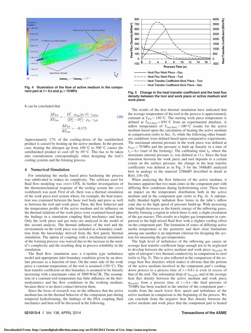
A tube made of the heat treatable steel 34MnB5 with an exter-nal diameter of 45 mm and a wall thickness of 2.2 mm and atube with the same dimensions made of air-hardenable steelMW1000L were used to obtain the work piece shown in Fig. 3. Ithas a special design that allows a detailed observation of media-based press hardening. Both a radius profile increasing from 5 mmto 12 mm and a circumference increasing over the length of thecomponent part was as much as 40%.
3.1 Calculating the Active Medium Temperature at theBeginning of Forming. In the following, the compression andheating process of the active medium (nitrogen) is consideredadiabatically in the entire system. In other words, the gas massdoes not exchange heat with its environments (for instance, pres-sure intensifier, pressure lines or sealing punch, etc.). Due to thevery fast forming of the tube to the demonstrator geometry theforming step was unattended in the calculation, the geometry usedwas the demonstrator geometry as seen in Fig. 3.
The following formulas and parameters (see Table 1) are takenfrom Gnielinski et al. [15]. The temperature of the active mediumwith adiabatic compression to pmax is
Tp;max ¼TFl
pFlpmax
� �j�1j
¼ 129:4 �C (1)
Since nitrogen interacts with its surroundings in the real compres-sion process, the correction factor k¼ 0.8 is introduced as a means
of adjustment that provides an inflow temperature of the activemedium TGas,Start� 100 �C.
3.2 Calculating the Cooling of the Semifinished Productby Heat Transfer to the Gaseous Active Medium. It is assumedthat the active medium is immediately heated up to the finaladjusting temperature when the gas flow into the semifinishedproduct. It does not entirely reach the final temperature after com-pleting the inflow process so that the gas continues to be heatedand some gas is pressed back isobar into the feed line at the speci-fied process pressure. The quantity of heat dissipated from this gasflowing back was not included in the calculation. This is the rea-son why the actual cooling-down of the semifinished product dueto heating up the active medium is some percentage points higherthan described below. The calculation is made with the meanedspecific heat capacity of nitrogen for a final temperature of 500 �Cand the ratio of the temperature change DTWS of the semifinishedproduct to the temperature change DTGas of the active medium isdetermined with the heat exchange occurring in the process.
Other assumptions were that no deformation was observed andconsequently no changes in volume. In addition, the tool coolingwas not included in the calculation.
Convection has not been included as this type of heat transferin solids is very low. Internal studies have shown that the coolingeffect is about 5% on the work piece. Thus, it is possible that con-vection can be neglected.
The change in the quantity of heat of the semifinished productwith the temperature change is
DQWS ¼ mWS � cpSt � DTWS (2)
With the mass of the semifinished product
mWS ¼ D2a � D2
i
� �� p
4� LWS � qSt (3)
it results
DQWS ¼ D2a � D2
i
� �� p
4� LWS � qSt � cpSt � DTWS (4)
The change in the quantity of heat of the gas in the semifinishedproduct at the temperature change is
DQGas ¼ mGas � cpGas � DTGas (5)
With the gas mass
mGas ¼ D2i
p4� LWS � qGas p; #ð Þ (6)
it results
DQGas ¼ D2i
p4� LWS � qGas p; #ð Þ � cpGas � DTGas (7)
Equations (4) and (7) give the following for the ratio of tempera-ture changes:
DTWS
DTGas
¼ DQWS
D2a � D2
i
� �� p
4� LWS � qSt � cpSt
�D2
i �p4� LWS � qGas p; #ð Þ � cpGas
DQGas
(8)
The following applies to the heat loss of the semifinished productto the gas:
DQgas ¼ � DQWS (9)
Fig. 3 Geometric dimensions of the demonstrator
Table 1 Geometrical and process conditions
Parameters Values
The pressure of the nitrogen in the compressed gasbottles pFL (MPa)
30
The maximum compression pressure pmax (MPa) 70The storage temperature of the nitrogen in thecompressed gas bottles TFL ( �C)
25
Adiabatic exponent nitrogen 1.5488Semifinished product length LWS (mm) 330External diameter of the semifinished product Da (mm) 45Internal diameter of the semifinished product Di (mm) 40.6The density of steel qSt (kg/m3) 7850Specific heat capacity von steel cpSt (kJ/kg) (The meanfor cooling off from 700 �C to 600 �C, [15])
0.93
The density of nitrogen qgas (kg/m)3 (at p¼ 70 MPa,T¼ 500 �C, [15])
233.1
The specific heat capacity of nitrogen cpgas (kJ/kg) (Themean for heating up from 100 �C to 500 �C, [15])
1.24
Journal of Manufacturing Science and Engineering APRIL 2014, Vol. 136 / 021013-3
Downloaded From: http://asmedigitalcollection.asme.org/ on 05/04/2014 Terms of Use: http://asme.org/terms
It can be concluded that
DTWS
DTGas
¼ �D2i � qGas p; #ð Þ � cpGas
D2a � D2
i
� �� qSt � cpSt
(10)
DTWS
DTGas
¼ �0:173
Approximately 17% of the cooling-down of the semifinishedproduct is caused by heating up the active medium. In the presentcase, heating the nitrogen up from 100 �C to 500 �C causes thesemifinished product to cool off by 69 �C. This has to be takeninto consideration correspondingly when designing the tool’scooling systems and the forming process.
4 Numerical Simulation
For simulating the media based press hardening the processwas subdivided to reduce its complexity. The software used forfluid flow modeling was ANSYS CFX. In further investigations ofthe thermomechanical response of the tooling system the ANSYS
workbench was used. First of all, there was a thermal simulationof the work piece-tool system where, for example, the heat transi-tion was examined between the basic tool body and press as wellas between the tool and work piece. Then, the flow behavior andthe temperature profile of the active medium and its influence onthe thermal relations of the work piece were examined based uponthe findings in a simulation coupling fluid mechanics and heat.Only the work piece and gas mass are analyzed in the model ofthis second analysis. The thermal influence of the tool and theenvironment on the work piece was included as a boundary condi-tion from the knowledge derived from the first purely thermalsimulation. The option of coupling with a mechanical simulationof the forming process was waived due to the increase in the mod-el’s complexity and the resulting drop in process reliability in thesimulation.
The fluid flow simulation uses a k-epsilon type turbulencemodel and appropriate inlet boundary condition given by an abso-lute pressure as a function of time. On the outer side of the workpiece a constant temperature of the tool is assumed (150 �C). Theheat transfer coefficient on this boundary is assumed to be linearlyincreasing with a maximum value of 3000 W/m2/K. The assump-tion of a constant tool temperature has little influence on the ther-modynamics and the flow conditions in the working medium,because there is no direct contact between them.
Since the focus of research was on the influence that the activemedium has on the thermal behavior of the component part duringtempered hydroforming, the findings of the FEA coupling fluidmechanics and heat will be discussed in the following.
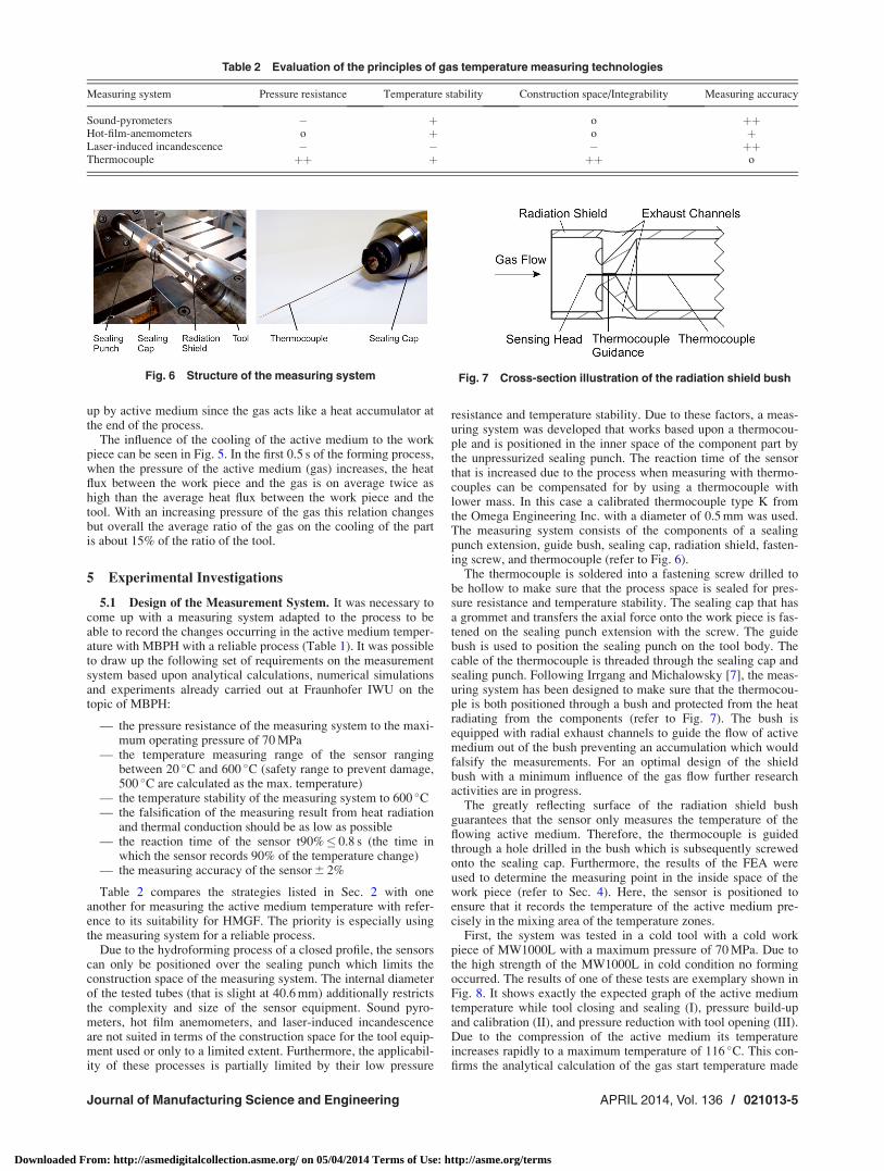
The results of the first thermal simulation have indicated thatthe average temperature of the tool in the process is approximatelyconstant at TWZ¼ 150 �C. The starting work piece temperature isdefined at TWS,Start¼ 850 �C from an experimental database. Ainflow temperature of TGas,Start¼ 100 �C results for the activemedium based upon the calculation of heating the active mediumat compression (refer to Sec. 3), while the following other bound-ary conditions were defined based upon comparative experiments.The maximum internal pressure in the work piece was defined atpmax¼ 70 MPa and the pressure is built up linearly in a time oftu¼ 6 s (start of the forming). The calibrating time tk, where themaximum internal pressure is, was defined at 11 s. Since the heattransition between the work piece and tool depends to a certainextent on the surface pressure, the change in the heat transfercoefficients was defined as in Fig. 5 for the 34MnB5 analyzedhere in analogy to the material 22MnB5 described in detail inRefs. [16–18].
When analyzing the flow behavior of the active medium, itbecomes apparent that two main zones in the component part withdiffering flow conditions during hydroforming exist. These havean impact on the temperature distribution both in the activemedium and in the component part (refer to Fig. 4). A substan-tially blended highly turbulent flow forms in the tube’s inflowzone due to the high speed of pressure build-up. With increasingtube length decreases as the kinetic energy of the inflowing gases,thereby forming a region in which there is only a slight circulationof the gas masses. This results in a higher gas temperature in com-parison to the high mixed fluid flow with a slighter cooling effecton the component part. The formation of zones of differing activemedia temperature in the geometry and their clear limitationsamong one another is an important criterion for designing the sys-tem for measuring the gas temperature.
The high level of turbulence of the inflowing gas causes anaverage heat transfer coefficient large enough not to be neglectedto develop between the active medium and work piece aGas/WS inspite of nitrogen’s low thermal conductivity in comparison to steel(refer to Fig. 5). This is also reflected in the comparison of the av-erage heat flux densities which makes it obvious that the portionof the active medium involved in the component part’s cooling-down process to a process time of t¼ 0.8 s is even in excess ofthat of the tool. The substantial drop of aGas/WS and of the averageheat flux density between the active medium and work pieceqGas/WS from a process time of t¼ 6 s—the final pressure of70 MPa has been reached in the interior of the component part—results from the much lower flow speed and turbulence of theactive medium in comparison to the beginning of the process. Wecan conclude from the negative heat flux density between theactive medium and work piece that the component part is heated
Fig. 4 Illustration of the flow of active medium in the compo-nent part at t 5 6 s and pi 5 70 MPa Fig. 5 Change in the heat transfer coefficient and the heat flux
density between the tool and work piece or active medium andwork piece
021013-4 / Vol. 136, APRIL 2014 Transactions of the ASME
Downloaded From: http://asmedigitalcollection.asme.org/ on 05/04/2014 Terms of Use: http://asme.org/terms
up by active medium since the gas acts like a heat accumulator atthe end of the process.
The influence of the cooling of the active medium to the workpiece can be seen in Fig. 5. In the first 0.5 s of the forming process,when the pressure of the active medium (gas) increases, the heatflux between the work piece and the gas is on average twice ashigh than the average heat flux between the work piece and thetool. With an increasing pressure of the gas this relation changesbut overall the average ratio of the gas on the cooling of the partis about 15% of the ratio of the tool.
5 Experimental Investigations
5.1 Design of the Measurement System. It was necessary tocome up with a measuring system adapted to the process to beable to record the changes occurring in the active medium temper-ature with MBPH with a reliable process (Table 1). It was possibleto draw up the following set of requirements on the measurementsystem based upon analytical calculations, numerical simulationsand experiments already carried out at Fraunhofer IWU on thetopic of MBPH:
— the pressure resistance of the measuring system to the maxi-mum operating pressure of 70 MPa
— the temperature measuring range of the sensor rangingbetween 20 �C and 600 �C (safety range to prevent damage,500 �C are calculated as the max. temperature)
— the temperature stability of the measuring system to 600 �C— the falsification of the measuring result from heat radiation
and thermal conduction should be as low as possible— the reaction time of the sensor t90%� 0.8 s (the time in
which the sensor records 90% of the temperature change)— the measuring accuracy of the sensor 6 2%
Table 2 compares the strategies listed in Sec. 2 with oneanother for measuring the active medium temperature with refer-ence to its suitability for HMGF. The priority is especially usingthe measuring system for a reliable process.
Due to the hydroforming process of a closed profile, the sensorscan only be positioned over the sealing punch which limits theconstruction space of the measuring system. The internal diameterof the tested tubes (that is slight at 40.6 mm) additionally restrictsthe complexity and size of the sensor equipment. Sound pyro-meters, hot film anemometers, and laser-induced incandescenceare not suited in terms of the construction space for the tool equip-ment used or only to a limited extent. Furthermore, the applicabil-ity of these processes is partially limited by their low pressure
resistance and temperature stability. Due to these factors, a meas-uring system was developed that works based upon a thermocou-ple and is positioned in the inner space of the component part bythe unpressurized sealing punch. The reaction time of the sensorthat is increased due to the process when measuring with thermo-couples can be compensated for by using a thermocouple withlower mass. In this case a calibrated thermocouple type K fromthe Omega Engineering Inc. with a diameter of 0.5 mm was used.The measuring system consists of the components of a sealingpunch extension, guide bush, sealing cap, radiation shield, fasten-ing screw, and thermocouple (refer to Fig. 6).
The thermocouple is soldered into a fastening screw drilled tobe hollow to make sure that the process space is sealed for pres-sure resistance and temperature stability. The sealing cap that hasa grommet and transfers the axial force onto the work piece is fas-tened on the sealing punch extension with the screw. The guidebush is used to position the sealing punch on the tool body. Thecable of the thermocouple is threaded through the sealing cap andsealing punch. Following Irrgang and Michalowsky [7], the meas-uring system has been designed to make sure that the thermocou-ple is both positioned through a bush and protected from the heatradiating from the components (refer to Fig. 7). The bush isequipped with radial exhaust channels to guide the flow of activemedium out of the bush preventing an accumulation which wouldfalsify the measurements. For an optimal design of the shieldbush with a minimum influence of the gas flow further researchactivities are in progress.
The greatly reflecting surface of the radiation shield bushguarantees that the sensor only measures the temperature of theflowing active medium. Therefore, the thermocouple is guidedthrough a hole drilled in the bush which is subsequently screwedonto the sealing cap. Furthermore, the results of the FEA wereused to determine the measuring point in the inside space of thework piece (refer to Sec. 4). Here, the sensor is positioned toensure that it records the temperature of the active medium pre-cisely in the mixing area of the temperature zones.
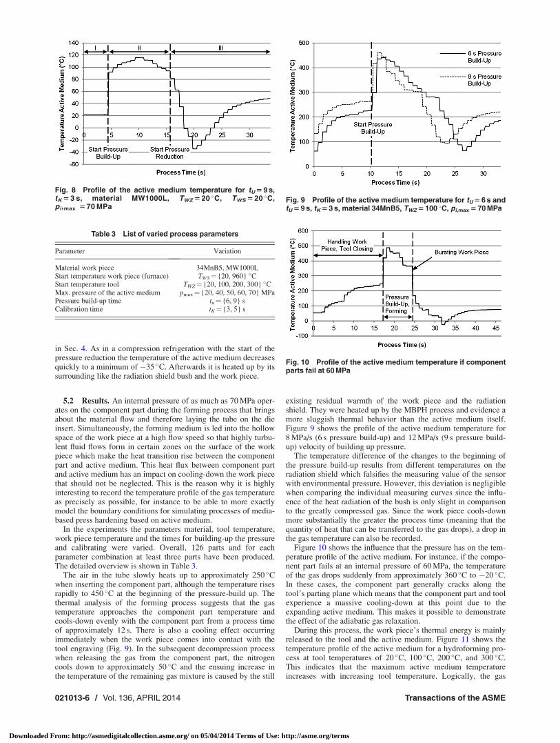
First, the system was tested in a cold tool with a cold workpiece of MW1000L with a maximum pressure of 70 MPa. Due tothe high strength of the MW1000L in cold condition no formingoccurred. The results of one of these tests are exemplary shown inFig. 8. It shows exactly the expected graph of the active mediumtemperature while tool closing and sealing (I), pressure build-upand calibration (II), and pressure reduction with tool opening (III).Due to the compression of the active medium its temperatureincreases rapidly to a maximum temperature of 116 �C. This con-firms the analytical calculation of the gas start temperature made
Table 2 Evaluation of the principles of gas temperature measuring technologies
Measuring system Pressure resistance Temperature stability Construction space/Integrability Measuring accuracy
Sound-pyrometers � þ o þþHot-film-anemometers o þ o þLaser-induced incandescence � � � þþThermocouple þþ þ þþ o
Fig. 6 Structure of the measuring system Fig. 7 Cross-section illustration of the radiation shield bush
Journal of Manufacturing Science and Engineering APRIL 2014, Vol. 136 / 021013-5
Downloaded From: http://asmedigitalcollection.asme.org/ on 05/04/2014 Terms of Use: http://asme.org/terms
in Sec. 4. As in a compression refrigeration with the start of thepressure reduction the temperature of the active medium decreasesquickly to a minimum of �35 �C. Afterwards it is heated up by itssurrounding like the radiation shield bush and the work piece.
5.2 Results. An internal pressure of as much as 70 MPa oper-ates on the component part during the forming process that bringsabout the material flow and therefore laying the tube on the dieinsert. Simultaneously, the forming medium is led into the hollowspace of the work piece at a high flow speed so that highly turbu-lent fluid flows form in certain zones on the surface of the workpiece which make the heat transition rise between the componentpart and active medium. This heat flux between component partand active medium has an impact on cooling-down the work piecethat should not be neglected. This is the reason why it is highlyinteresting to record the temperature profile of the gas temperatureas precisely as possible, for instance to be able to more exactlymodel the boundary conditions for simulating processes of media-based press hardening based on active medium.
In the experiments the parameters material, tool temperature,work piece temperature and the times for building-up the pressureand calibrating were varied. Overall, 126 parts and for eachparameter combination at least three parts have been produced.The detailed overview is shown in Table 3.
The air in the tube slowly heats up to approximately 250 �Cwhen inserting the component part, although the temperature risesrapidly to 450 �C at the beginning of the pressure-build up. Thethermal analysis of the forming process suggests that the gastemperature approaches the component part temperature andcools-down evenly with the component part from a process timeof approximately 12 s. There is also a cooling effect occurringimmediately when the work piece comes into contact with thetool engraving (Fig. 9). In the subsequent decompression processwhen releasing the gas from the component part, the nitrogencools down to approximately 50 �C and the ensuing increase inthe temperature of the remaining gas mixture is caused by the still
existing residual warmth of the work piece and the radiationshield. They were heated up by the MBPH process and evidence amore sluggish thermal behavior than the active medium itself.Figure 9 shows the profile of the active medium temperature for8 MPa/s (6 s pressure build-up) and 12 MPa/s (9 s pressure build-up) velocity of building up pressure.
The temperature difference of the changes to the beginning ofthe pressure build-up results from different temperatures on theradiation shield which falsifies the measuring value of the sensorwith environmental pressure. However, this deviation is negligiblewhen comparing the individual measuring curves since the influ-ence of the heat radiation of the bush is only slight in comparisonto the greatly compressed gas. Since the work piece cools-downmore substantially the greater the process time (meaning that thequantity of heat that can be transferred to the gas drops), a drop inthe gas temperature can also be recorded.
Figure 10 shows the influence that the pressure has on the tem-perature profile of the active medium. For instance, if the compo-nent part fails at an internal pressure of 60 MPa, the temperatureof the gas drops suddenly from approximately 360 �C to �20 �C.In these cases, the component part generally cracks along thetool’s parting plane which means that the component part and toolexperience a massive cooling-down at this point due to theexpanding active medium. This makes it possible to demonstratethe effect of the adiabatic gas relaxation.
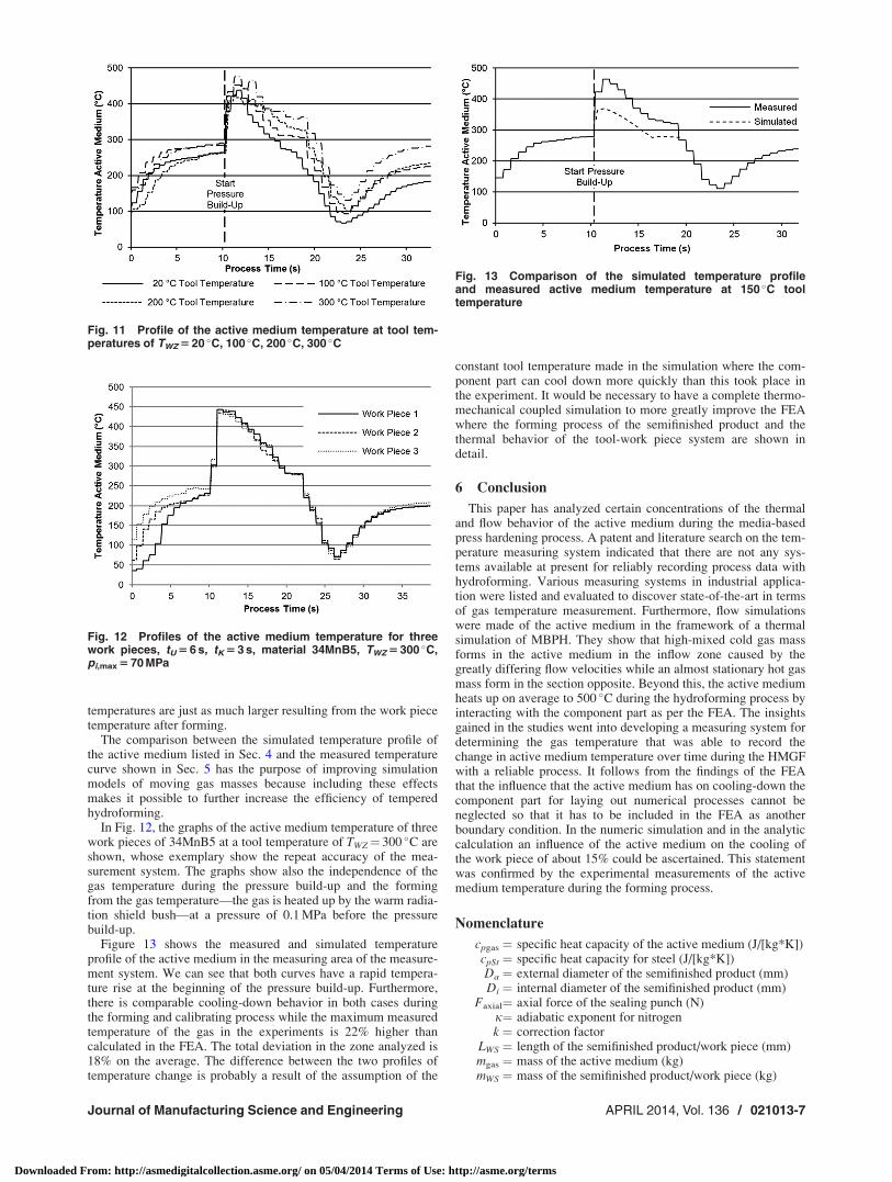
During this process, the work piece’s thermal energy is mainlyreleased to the tool and the active medium. Figure 11 shows thetemperature profile of the active medium for a hydroforming pro-cess at tool temperatures of 20 �C, 100 �C, 200 �C, and 300 �C.This indicates that the maximum active medium temperatureincreases with increasing tool temperature. Logically, the gas
Table 3 List of varied process parameters
Parameter Variation
Material work piece 34MnB5, MW1000LStart temperature work piece (furnace) TWS¼ {20, 960} �CStart temperature tool TWZ¼ {20, 100, 200, 300} �CMax. pressure of the active medium pmax¼ {20, 40, 50, 60, 70} MPaPressure build-up time tu¼ {6, 9} sCalibration time tK¼ {3, 5} s
Fig. 9 Profile of the active medium temperature for tU 5 6 s andtU 5 9 s, tK 5 3 s, material 34MnB5, TWZ 5 100 �C, pi,max 5 70 MPa
Fig. 10 Profile of the active medium temperature if componentparts fail at 60 MPa
Fig. 8 Profile of the active medium temperature for tU 5 9 s,tK 5 3 s, material MW1000L, TWZ 5 20 �C, TWS 5 20 �C,pi,max 5 70 MPa
021013-6 / Vol. 136, APRIL 2014 Transactions of the ASME
Downloaded From: http://asmedigitalcollection.asme.org/ on 05/04/2014 Terms of Use: http://asme.org/terms
temperatures are just as much larger resulting from the work piecetemperature after forming.
The comparison between the simulated temperature profile ofthe active medium listed in Sec. 4 and the measured temperaturecurve shown in Sec. 5 has the purpose of improving simulationmodels of moving gas masses because including these effectsmakes it possible to further increase the efficiency of temperedhydroforming.
In Fig. 12, the graphs of the active medium temperature of threework pieces of 34MnB5 at a tool temperature of TWZ¼ 300 �C areshown, whose exemplary show the repeat accuracy of the mea-surement system. The graphs show also the independence of thegas temperature during the pressure build-up and the formingfrom the gas temperature—the gas is heated up by the warm radia-tion shield bush—at a pressure of 0.1 MPa before the pressurebuild-up.
Figure 13 shows the measured and simulated temperatureprofile of the active medium in the measuring area of the measure-ment system. We can see that both curves have a rapid tempera-ture rise at the beginning of the pressure build-up. Furthermore,there is comparable cooling-down behavior in both cases duringthe forming and calibrating process while the maximum measuredtemperature of the gas in the experiments is 22% higher thancalculated in the FEA. The total deviation in the zone analyzed is18% on the average. The difference between the two profiles oftemperature change is probably a result of the assumption of the
constant tool temperature made in the simulation where the com-ponent part can cool down more quickly than this took place inthe experiment. It would be necessary to have a complete thermo-mechanical coupled simulation to more greatly improve the FEAwhere the forming process of the semifinished product and thethermal behavior of the tool-work piece system are shown indetail.
6 Conclusion
This paper has analyzed certain concentrations of the thermaland flow behavior of the active medium during the media-basedpress hardening process. A patent and literature search on the tem-perature measuring system indicated that there are not any sys-tems available at present for reliably recording process data withhydroforming. Various measuring systems in industrial applica-tion were listed and evaluated to discover state-of-the-art in termsof gas temperature measurement. Furthermore, flow simulationswere made of the active medium in the framework of a thermalsimulation of MBPH. They show that high-mixed cold gas massforms in the active medium in the inflow zone caused by thegreatly differing flow velocities while an almost stationary hot gasmass form in the section opposite. Beyond this, the active mediumheats up on average to 500 �C during the hydroforming process byinteracting with the component part as per the FEA. The insightsgained in the studies went into developing a measuring system fordetermining the gas temperature that was able to record thechange in active medium temperature over time during the HMGFwith a reliable process. It follows from the findings of the FEAthat the influence that the active medium has on cooling-down thecomponent part for laying out numerical processes cannot beneglected so that it has to be included in the FEA as anotherboundary condition. In the numeric simulation and in the analyticcalculation an influence of the active medium on the cooling ofthe work piece of about 15% could be ascertained. This statementwas confirmed by the experimental measurements of the activemedium temperature during the forming process.
Nomenclature
cpgas ¼ specific heat capacity of the active medium (J/[kg*K])cpSt ¼ specific heat capacity for steel (J/[kg*K])Da ¼ external diameter of the semifinished product (mm)Di ¼ internal diameter of the semifinished product (mm)
Faxial¼ axial force of the sealing punch (N)j¼ adiabatic exponent for nitrogenk ¼ correction factor
LWS ¼ length of the semifinished product/work piece (mm)mgas ¼ mass of the active medium (kg)mWS ¼ mass of the semifinished product/work piece (kg)
Fig. 12 Profiles of the active medium temperature for threework pieces, tU 5 6 s, tK 5 3 s, material 34MnB5, TWZ 5 300 �C,pi,max 5 70 MPa
Fig. 13 Comparison of the simulated temperature profileand measured active medium temperature at 150 �C tooltemperature
Fig. 11 Profile of the active medium temperature at tool tem-peratures of TWZ 5 20 �C, 100 �C, 200 �C, 300 �C
Journal of Manufacturing Science and Engineering APRIL 2014, Vol. 136 / 021013-7
Downloaded From: http://asmedigitalcollection.asme.org/ on 05/04/2014 Terms of Use: http://asme.org/terms
pFL¼ the pressure of the nitrogen in compressed gas bottles(MPa)
pmax¼ maximum compression pressure (MPa)pi¼ internal pressure (MPa)
QGas/WS ¼ heat flux density between the active medium and workpiece (W/m2)
R¼ radius (mm)tu ¼ forming time (s)tk ¼ calibrating time (s)
t90% ¼ the sensor’s reaction time where 90% of thetemperature change is recorded (s)
T ¼ process time (s)TGas,Start ¼ active medium temperature at the beginning of the
forming process (�C)Tp,max ¼ temperature of the active medium at pmax (�C)
TWZ¼ tool temperature (�C)TWS¼ work piece temperature (�C)
xpusher¼ pusher path of the sealing punch (mm)aGas/WS ¼ heat transfer coefficient between the active medium
and work piece (W/[m2*K])DQWS ¼ changes in the quantity of heat of the semifinished
product/work piece (J)DQgas ¼ change in the quantity of heat of the active medium (J)DTgas ¼ temperature change in the active medium (K)DTWS ¼ temperature change in the semifinished product/work
piece (K)H ¼ temperature (K)qSt ¼ density of steel (kg/m3)
qgas ¼ density of the active medium (kg/m3)
References[1] G€oschel, A., Sterzing, A., and Sch€onherr, J., 2011, “Balancing Procedure for
Energy and Material Flows in Sheet Metal Forming,” CIRP J. Manuf. Sci.Technol., 4(2), pp. 170–179.
[2] Lang, L. H., Wang, Z. R., Kang, D. C., Yuan, S. J., Zhang, S. H., Danckert, J.,and Nielsen, K. B., 2004, “Hydroforming Highlights: Sheet Hydroforming andTube Hydroforming,” J. Mater. Process. Technol., 151(1–3), pp. 165–177.
[3] Abedrabbo, N., Worswick, M., Mayer, R., and van Riemsdijk, I., 2009,“Optimization Methods for the Tube Hydroforming Process Applied to
Advanced High-Strength Steels With Experimental Verification,” J. Mater. Pro-cess. Technol., 209(1), pp. 110–123.
[4] Karbasian, H., and Tekkaya, A. E., 2010, “A Review on Hot Stamping,”J. Mater. Process. Technol., 210(15), pp. 2103–2118.
[5] Keigler, M., Bauer, H., Harrison, D., and De Silva, A. K. M., 2005, “Enhancingthe Formability of Aluminium Components Via Temperature ControlledHydroforming,” J. Mater. Process. Technol., 167(2–3), pp. 363–370.
[6] Neugebauer, R., Bouzakis, K.-D., Denkena, B., Klocke, F. Sterzing, A., Tek-kaya, A. E., and Wertheim, R., 2011, “Velocity Effects in Metal Forming andMachining Processes,” CIRP Ann., 60(2), pp. 627–650.
[7] Irrgang, K., and Michalowsky, L., 2004, Temperaturmesspraxis mit Wider-standsthermometern und Thermoelementen, Vulkan Verlag, Essen, Germany,pp. 176–178.
[8] L€onnermark, A., Hedekvist, P., and Ingason, H., 2008, “Gas TemperatureMeasurements Using Fibre Bragg Grating During Fire Experiments in aTunnel,” Fire Saf. J., 43(2), pp. 119–126.
[9] Epple, B., Leithner, R., Linzer, W., and Walther, H., 2009, Simulation vonKraftwerken und w€armetechnischen Anlagen, Springer Verlag Wien, NewYork.
[10] Eklund, T. I., and Dobbins, R. A., 1977, “Application of the Hot Wire Ane-mometer to Temperature Measurement in Transient Gas Flows,” Int. J. HeatMass Transfer, 20(10), pp. 1051–1058.
[11] Siemens A. G., 1999, “Verfahren und Vorrichtung zur Bestimmung der Gas-temperatur des Abgases einer Brennkraftmaschine,” Patent DE 199 13 910 C2.
[12] Ardekani, M. A., and Farhani, F., 2009, “Experimental Study on Response ofHot Wire and Cylindrical Hot Film Anemometers Operating Under VaryingFluid Temperatures,” Flow Meas. Instrum., 20(4–5), pp. 174–179.
[13] ABB Research Ltd, 1999, “Verfahren und Vorrichtung zur Gastemperatur-messung mit laserinduzierter Weissglut-Pyrometrie,” Patent DE 199 45 640A1.
[14] Ryser, R., Gerber, T., and Dreier, T., 2009, “Soot Particle Sizing During High-Pressure Diesel Spray Combustion Via Time-Resolved Laser-InducedIncandescence,” Combust. Flame, 156(1), pp. 120–129.
[15] Gnielinski, V., Kabalec, S., Kind, M., Martin, H., Mewes, D., Faber, K., andStephan, P., 2006, VDI-W€armeatlas, Springer Verlag, Berlin.
[16] Brosius, A., Karbasian, H., Tekkaya, A. E., Lechler, J., Merklein, M., Geiger,M., Springer, R., Schaper, M., Bach, F. W., and Hoffmann, H., 2007,“Modellierung und Simulation der Warmblechumformung: Aktueller Stand undzuk€unftiger Forschungsbedarf,” Erlanger Workshop Warmblechumformung,Tagungsband 2, Erlangen, Germany, pp. 37–58.
[17] Merklein, M., and Lechler, J., 2008, “Determination of Material and ProcessCharacteristics for Hot Stamping Processes of Quenchenable Ultra HighStrength Steels With Respect to a FE-Based Process Design,” SAE Int. J.Mater. Manuf., 1(1), pp. 411–426.
[18] Svec, T., and Merklein, M., 2010, “Auswirkungen SpezifischerAbk€uhlbedingungen auf den W€arme€ubergang bei Pressh€artprozessen,” ErlangerWorkshop Warmblechumformung, Tagungsband 5, Erlangen, Germany, pp.121–140.
021013-8 / Vol. 136, APRIL 2014 Transactions of the ASME
Downloaded From: http://asmedigitalcollection.asme.org/ on 05/04/2014 Terms of Use: http://asme.org/terms