No. 2, 2015 Mining & Metallurgy Engineering Bor 53 MINING AND METALLURGY INSTITUTE BOR ISSN: 2334-8836 (Štampano izdanje) UDK: 622 ISSN: 2406-1395 (Online) UDK: 622.261:581.5(045)=111 DOI:10.5937/MMEB1502053M Miodrag Miljković * , Rodoljub Stanojlović * , Jovica Sokolović * DETERMINATION THE NECESSARY STRENGHT OF STOPE FILLINGS AT TOTAL LAYER EXCAVATION ** Abstract The basic aims of layer excavation by filling methods are: increasing or total layer spending without ore impoverishment, layer excavation in complex mining and geological conditions, envi- ronmental factors preservation, improvement of ergonomic and safety work conditions and recir- culation the waste material. For achievement of these aims, it is necessary to put in the stope the filling material of appro- priate physical and mechanical characteristics, especially the pressure strength. This work pre- sents a discussion of procedure of filling material selection with necessary strength, and applica- tion of filling stoping methods at complete layer excavation and protection of the earth surface and objects on it from damages. Keywords: total excavation, filling of the stopes, stoping strength * University of Belgrade, Technical Faculty Bor, Vojske Jugoslavije 12, 19210, Bor, Serbia, e-mail address: [email protected]** This paper presents the results of the Projects TR 33007, “Implementation of Modern Technical- Technological and Environmental Solutions in the Existing Production Systems of the Copper Mine Bor and Copper Mine Majdanpek” and TR 33038 “Improving Technology of Exploitation and Pro- cessing of Copper Ore with Monitoring the Living and Working Environment in the RTB Bor Group”, funded by Ministry of Education, Science and Technological Development of the Republic of Serbia. The authors are grateful to the Ministry for financial support 1 INTRODUCTION Complete excavation of the mineral ore layer without depletion of mineral ore and with preservation the environmental faction in the exploitation field can be only realized by the mining method with filling the cavi- ties in ascending or descending order of excavation and filling [1]. Depending on the objectives of full deposit excavation with filling the cavities, the required strength of backfill can be determined and selection the type of filling material with which that the strength can be achieved [2]. This can be achieved by applying of so- lidifying backfill [3]. Completely obtaining of layers without getting ore dilution can be carried by the following groups of excavation methods [4]: 1. The central excavation of corridors, steep ore veins and lenses is a) from bottom to top, standing of equipment on the back fill, b) from top to bottom, under backfill, when the equipment is at a solid rock (ore). 2. Single-or multi-layer excavation of powerful ore deposits; a) vertically layered
Transcript
No. 2, 2015 Mining & Metallurgy Engineering Bor 53
MINING AND METALLURGY INSTITUTE BOR ISSN: 2334-8836 (Štampano izdanje)
This paper presents the results of the Projects TR 33007, “Implementation of Modern Technical-
Technological and Environmental Solutions in the Existing Production Systems of the Copper Mine
Bor and Copper Mine Majdanpek” and TR 33038 “Improving Technology of Exploitation and Pro-
cessing of Copper Ore with Monitoring the Living and Working Environment in the RTB Bor
Group”, funded by Ministry of Education, Science and Technological Development of the Republic of
Serbia. The authors are grateful to the Ministry for financial support
1 INTRODUCTION
Complete excavation of the mineral ore
layer without depletion of mineral ore and
with preservation the environmental faction
in the exploitation field can be only realized
by the mining method with filling the cavi-
ties in ascending or descending order of
excavation and filling [1]. Depending on
the objectives of full deposit excavation
with filling the cavities, the required
strength of backfill can be determined and
selection the type of filling material with
which that the strength can be achieved [2].
This can be achieved by applying of so-
lidifying backfill [3].
Completely obtaining of layers without
getting ore dilution can be carried by the
following groups of excavation methods [4]:
1. The central excavation of corridors,
steep ore veins and lenses is a) from bottom
to top, standing of equipment on the back
fill, b) from top to bottom, under backfill,
when the equipment is at a solid rock (ore).
2. Single-or multi-layer excavation of
powerful ore deposits; a) vertically layered
No. 2, 2015 Mining & Metallurgy Engineering Bor 54
excavation from bottom to top (equipment
moves on the backfill), b) horizontal layered
excavation from top to bottom and beneath
concrete slab (equipment is moving on solid
ground).
3. Sublevel excavation of ore deposits
with subsequent excavation back filling; a)
curing over burden with movement of the
excavation front from bottom to top, b) un-
der concrete slabs, by excavation back fill-
ing with curing over burden (excavation
fronts are moving from top to bottom.
4. Chamber pillar ore deposits excava-
tion with ore storage, filling of stope by so-
lidifying backfill and subsequent obtaining
the protective ore pillars in filling by the
same stoping method. It can be applied as: a)
panel and b) cross-excavation of chambers.
Depending on the order of mining,
construction and excavation geometry,
objectives, implementation costs of exca-
vation methods, physical and mechanical
characteristics of the deposit and associat-
ed rocks, as well as the depth of the de-
posit, the necessary strength of backfill
will be determined.
2 RELATIONS BETWEEN
ASSOCIATED DEPOSITS ROCKS
AND FILLED EXCAVATED
AREAS IN THE DEPOSIT
Strength of solidifying backfill is satis-
factory (normative) if it is possible to secure
the opening of the artificial, (backfilling)
massive of designed mining areas and exca-
vation, and if the earth's surface and objects
above the deposits can be maintained from
deformation. The gravitational and tectonic
(static) and blasting (dynamic) powers have
effect on massive from backfilling material.
Mass of backfilled excavation may be sub-
jected to deformation under pressure, stret-
ching, shearing, bending in uniaxial, biaxial
and volume of stressed state. Strength of
filling material shall be selected to suit the
strength of the uniaxial pressure For choice
and control the necessary strength of filling
materials considering the role to be met,
regardless of the character of the load. The
required strength of filling material is deter-
mined by one or more factors:
a) stability (holding) of vertical open
sides,
b) horizontally open ceilings,
c) the allowable deformation of the
earth's surface,
d) the ability to move of equipment
on the backfill surface, etc.
Mass from the filling material and sur-
rounding rocks, in certain circumstances,
form a complex spatial system backfill-rock.
The main structural elements of such system
roof and floor rocks and filling space are
very different.
Calculation of strength of backfill is
based on the knowledge of the stress-
deformation characteristics of natural and
artificial rock, (from backfill), mass in the
excavation area, character of their interac-
tion and is reduced to solution of three tasks.
1. Finding a load to the mass of back-
filled excavation,
2. Determination of stresses in the
backfill as an integral element of
the system of rocks (rocks back-
filled area),
3. Determining the necessary strength
of backfill, resulting in the required
ratio of manifestation (safety) for a
given stress state, with the impact
of other technological factors in the
excavation of deposits.
Load to an artificially massive backfill of
excavation depends on: the physical-mecha-
nical characteristics of surrounding rocks,
stress in them, backfilled excavation geome-
try, (size, depth and slope) and physical-
mechanical characteristics of backfill, as
well as the role of construction of backfilling
materials fulfill during the further exploita-
tion and termination of deposit exploitation.
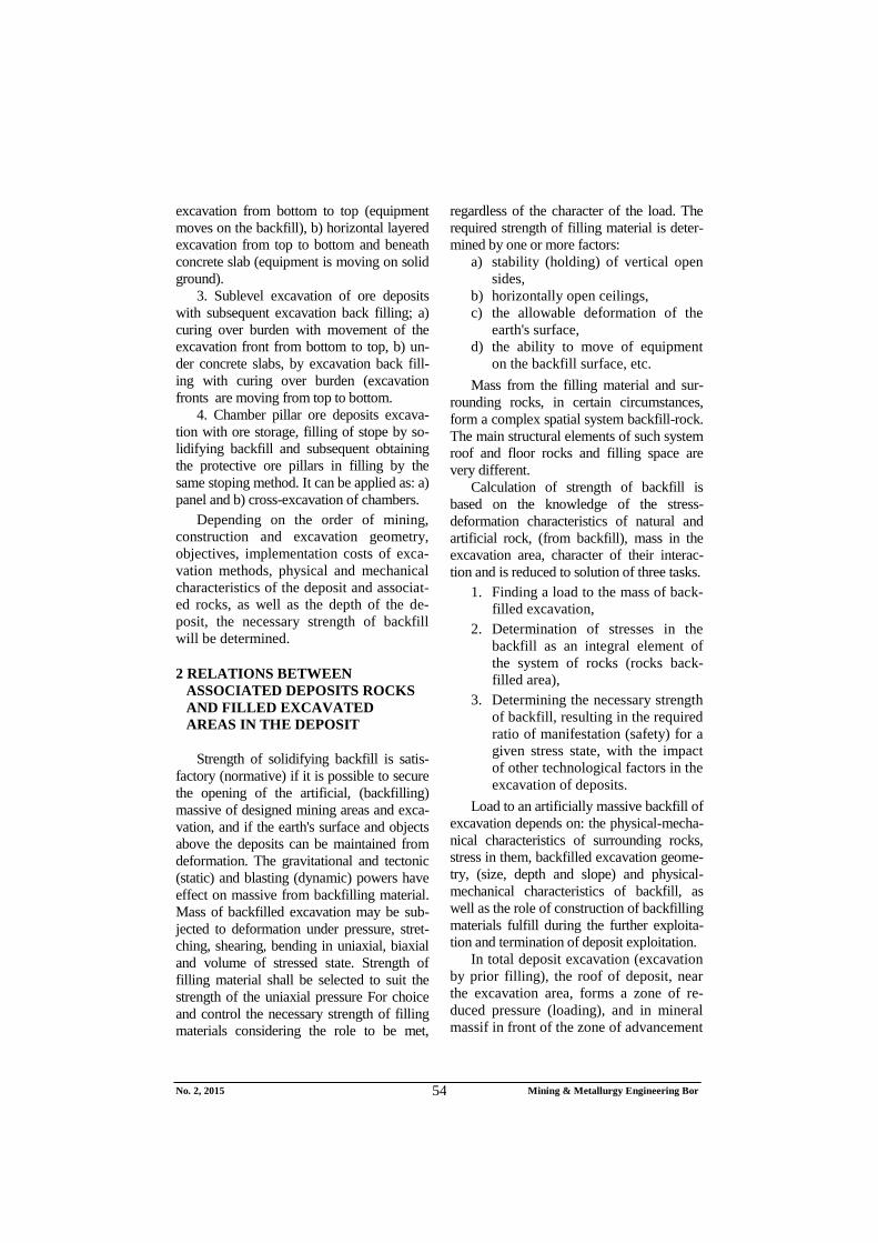
In total deposit excavation (excavation
by prior filling), the roof of deposit, near
the excavation area, forms a zone of re-
duced pressure (loading), and in mineral
massif in front of the zone of advancement
No. 2, 2015 Mining & Metallurgy Engineering Bor 55
occurs a zone of high support pressure, Fig.
1 With the increase in width of excavated
space and backfilled space, the roofing
rocks and backfill in the space filled, behave
like the surrounding rocks and permissive
support units, until backfill receives the en-
tire burden of roofing rocks pillar. Load on
the excavation comes from roofing rock
slab, which is partly supported on the back-
filled part of excavation area, and partially
on the ore massif. Dimensions of unloading
zones are proportional to the deformation
characteristics of the backfill, . Defor-
mation characteristics of backfill depend on
the type of backfill and installation. At
3% moving of leaning rocks is per-
formed by folding without cracking and
fragmentation. At 3% in the roof occurs
cracking and layering of rocks. The value of
stress concentration coefficient in the ore
massif is determined by the width of exca-
vated space L and the stress concentration in
the ore massif, by the formula:
Kk = 2.1 – 1.1 5..1)80/(Le
Kk = (0.8 le n+14)H-0.33
where:
e - base of natural logarithm
L - width of excavated space m, L = n le
le - excavation width (tape, layer) in get-
ting (the equivalent pillar width of the
excavation ceiling)
n - number of tracks in simultaneous get-
ting to achievement the critical width
lk= n le
H - depth of works for which stresses in
the roof are related ;
= gH, (Pa)
Tests have shown that maximum pres-
sure of support at width of excavation space
L=30-40 m is (1.5 – 1.6) gH. Maximum is
at 15 - 20 m from the forehead of excava-
tion front , and the width of stressed zone is
about 50 m. Backfill material suffers loa-
ding only at width of excavated space 40 -
60 m.
During excavation of backfill below de-
posits, backfill material plays the role of
artificial roofing below which the unloading
zone is also formed in the area of excava-
tion and zone of support pressure on the
sides in front of excavation forehead and in
the backfilled space. The load depends of
backfill weight and roofing rocks pressure,
if they already have the suffered defor-
mations.
3 REQUIRED BACKFILL
STRENGHT AT CHAMBERS
EXCAVATION WITH BACKFILL
Economical massive excavation of the
low-grade (low value) ore deposits applying
excavation method with filling the cavities,
can only be performed by the use of highly
productive excavation methods. The cham-
ber pillar excavation method can be one of
them with ore storage, with chamber back-
filling after ore discharge by curing backfill
and subsequent obtaining of protective pil-
lars of ore using the same stoping method,
for which an analysis of required backfill
strength have to be carried out (Fig. 2). The
required backfill strength can be viewed for
three stages where a pillar of backfill materi-
al can be found in excavation area.
1. When the chamber is located be-
tween the protective pillars from
ore (stage I),
2. When the chamber is located be-
tween the pillar of ore and the pil-
lar from hardened backfill adjacent
to the excavated chamber (stage II)
or backfilled space,
3. When the chamber is located be-
tween the protective pillars from
hardened backfill.
1. In the first stage backfill in the
chamber will not be burdened by any verti-
cal load of more lying rocks, except its own
mass. Lateral load in the pillar of backfill
may occur due to deformations the sides of
chamber. The stable range of chamber cei-
ling (le) is determined from strict conditions
No. 2, 2015 Mining & Metallurgy Engineering Bor 56
of stability the mine premises and excava-
tion and chamber ceiling. Stability of the
undermined ceiling to critical deformation
is determined from the condition.
gr g d
where: gd - allowable deformation of ceilings at
which the ceiling of chamber is sta-ble,
gr - relative deformation of chamber cei-ling. It is determined by the formula:
gr = 1/ 1+(HR/le)f
HR - reduced for monolithic mass requi-rements, depth of chamber ceiling
HR=(1-Kg) Hk
Hk - thickness of the roofing sediments
at the surface to the plane of ceiling
chamber. Kg - stability loss coefficient of ceiling
due to cracking and structural pro-perties of rocks (depend of RQD characteristics). Its value can be de-termined based on the percentage of the extracted core.
Kg = 0.84 + 0.01 Nj – 0.0002 Nj2
where:
Nj - percentage of extracted core (often
showing a high value),
f - coefficient of rocks strength by Pro-togakonov,
le - equivalent stable range of chamber cavity (width).
Equivalent stable range (width) of cha-
mber can be determined, if adopted bounda-
ry conditions, and solved explicitly by the
formula le.
g < 0.001 - stable range of chamber,
g = (0.001-0.04) - state between stability
and complete caving in,
g 0.04 - complete collapse of leaning
roofing
fR
ff
Re
g
gH
g
gHl
11, (m)
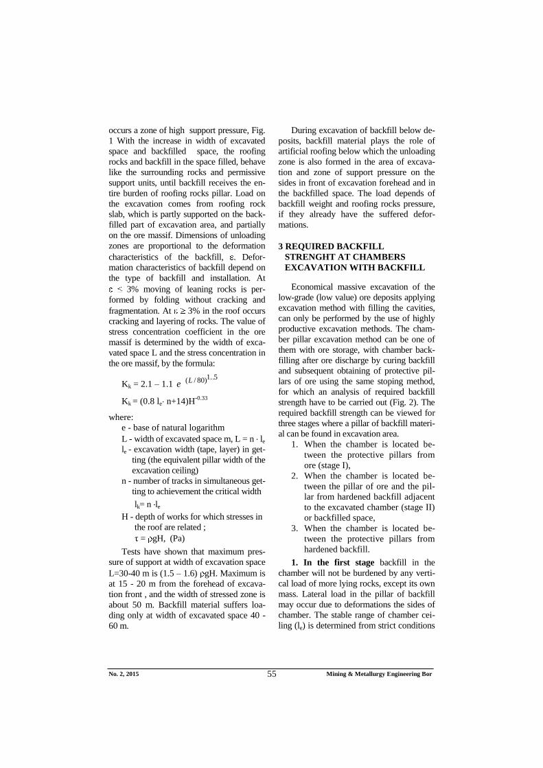
Stresses will be concentrated in the sides
of chamber as shown in Fig. 1.
They will not be transferred to the back-
fill in the chamber, or more chambers. While
undermined cavity beneath the roofing
reaches a critical range (talking about the
cavity because at excavation filling it will
never completely include roofing materials).
lk = Hk f
g
g
1, (m) at g > 0.04
Figure 1 Chart of changes of the stress concentration in the ore and massif of the backfill
2 The second stage of chamber position
in the excavation and backfilled space is the
most common. The exploitation of large
steep ore bodies, critical range of excavated
areas where the roof caving occurs, is less
than the length of excavation front. Blocks
of caved rocks will load the backfilled space
if the backfill is compressible (plastic) that
will result in larger deformations in the roof,
and even to the deformations of the earth's
No. 2, 2015 Mining & Metallurgy Engineering Bor 57
surface (in shallower deposits). Yet the filled
space represents the relief zone. At the mo-
ving of excavation front from the periphery
of the ore body to the opening premises, the
following cases of stress can be logged:
a) Above the first of excavated chambers
at width of excavated space L = nle < lk (sta-
ble equivalent widths), the clamping stresses
appeared in the excavation roof and the
comprehensive stresses are concentrated on
the sides of excavation and undisturbed
rocks, depending on the width of excavated
space. Coefficient of power concentration is
determined by formula Kk, and vertical
stress in the massif is:
p=Kk sgH, (Pa)
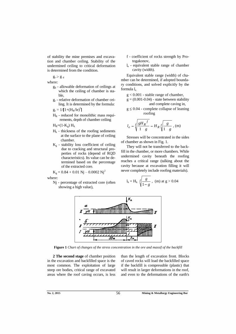
Horizontal stress y on the chamber
side according to Fig. 2 is:
gHK sky1
, (Pa)
where:
- is the Pauson coefficient =(0.4 0.6)
(coefficient of side load).
Figure 2 Scheme for calculation the stress of protective pillars on backfill in the chamber
Concentration of stress coefficient as in
front of the forehead excavation front in the
mine, and as in the final pillars of the back-
fill will increase with each subsequent exca-
vation chamber, until the range of the exca-
vated space does not exceed the critical
width L>lk.
b) When it excavated more chambers, so
that the range of excavated space L becomes
unstable or crashes, it will cause occurrence
vertical stress in the backfill massif. Size of
the vertical stress, which can occur in artifi-
cial pillars of the backfill, is calculated using
the principle of simultaneous deformation of
combined supports, pillars of the ores and
pillars of backfill by the formula:
zz
z
spz
ksa gh
E
ESS
gHSK 6
61 10
)77,0(10
where:
s; z - density of rock material and
backfill material
H - depth of excavated
ceiling space
Sk; Sz - surface of ore pillars and
pillars of the backfill
Es; Ez - deformation modulus of ore
deposit and backfill material
Ka – impact coefficient of the deposit in-
clination angle to the load of backfill
Ka=cos2
- sin2
; = /(1 - )
hz - height of backfill pillar (height of
excavated and backfilled space)
- deposit inclination angle (slope of
filled cavity).
No. 2, 2015 Mining & Metallurgy Engineering Bor 58
Strength of backfill in the excavated area
must be greater than vertical stress that
occurs in the backfill to prevent loosening
and compacting of backfill and further de-
formation of roofing.
z > 1
In deep thin deposit, a compacting of
backfill may be allowed to a certain height,
at which the illicit deformations of the
earth's surface will not occur and the reduc-
tion of safety coefficient K 4 .
c) The final event of the second stage
occurs at the movement of excavation front
so that the getting of chambers is performed
between the massive of ore and massive of
backfill. The roof is based on excavated ore
front, with console of not supported roofing
on backfill of length l < l ; l < n le and part
of the roofing which is caved under more
lying masses. Chamber of excavation is lo-
cated under the console, where the vertical
stresses are reduced. Maximum vertical
stress is in front of excavation front in ore
massif. And in the excavation chamber at a
distance l < lk there is a zone of reduced ver-
tical stress. At a distance L>lk, the massive
and backfill are under concentrated vertical
stress, the same as in the ore massif. For
finding the necessary strength of backfill to
preserve the earth's surface from defor-
mation, it is necessary to take into account
the possible allowed backfill compression at
which there will be no damage to the earth's
surface.
For blind isolated deposits with proper
form, influence of size (height) of excavated
areas and backfilled area to deformation
(settlement) of the earth's surface, depending
on the compression properties of backfill, is
evaluated based on the safety coefficient
whose value should be greater than are per-
mitted by Table 1 [5].
Ks > Kd = H / P
The vertical acceptable size of defor-
mation of backfilled space P is determined
by the formula:
P = o hz (1-e) 1/ z, (m)
where:
P - decrease of height of pillars by ba-
ckfill under load 1, (m)
1 - acting vertical stress, (Pa)
o - deformation characteristics of cer-
tain type of backfill
hz - thickness (height) of backfill pillar
z - strength of backfill to the pressure
Ks - safety coefficient which evaluates
the stability of roofing.
The necessary or sufficient strength of
backfill z for thin deep deposits can be cal-
culated from the above formula, where due
to roofing load backfill will be overloaded
and partially compressed. Permitted backfill
compression will be P = H/Kd, and the
necessary strength of backfill z:
)ln(
ln1
P
hzoz , (Pa)
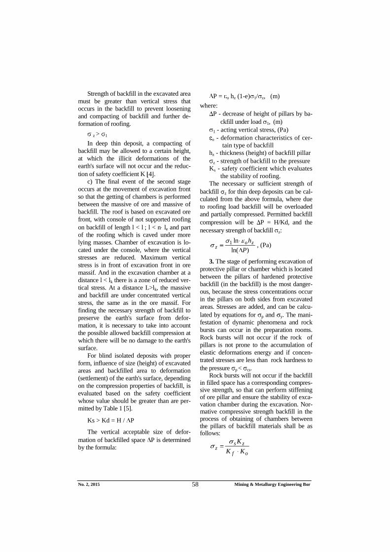
3. The stage of performing excavation of
protective pillar or chamber which is located
between the pillars of hardened protective
backfill (in the backfill) is the most danger-
ous, because the stress concentrations occur
in the pillars on both sides from excavated
areas. Stresses are added, and can be calcu-
lated by equations for p and y. The mani-
festation of dynamic phenomena and rock
bursts can occur in the preparation rooms.
Rock bursts will not occur if the rock of
pillars is not prone to the accumulation of
elastic deformations energy and if concen-
trated stresses are less than rock hardness to
the pressure p < cs. Rock bursts will not occur if the backfill
in filled space has a corresponding compres-sive strength, so that can perform stiffening of ore pillar and ensure the stability of exca-vation chamber during the excavation. Nor-mative compressive strength backfill in the process of obtaining of chambers between the pillars of backfill materials shall be as follows:
of
zsz
KK
K
No. 2, 2015 Mining & Metallurgy Engineering Bor 59
where:
s - stress in backfill pillars,
s = KaKh gH Ls/106Lz,
Kz -coefficient of safety Kz=(1.5-3),
Kf - coefficient of pillar form (given the
influence of shape and dimensions
of pillar on supporting ability
Kf=(a/hs)0.5
at a>hs or Kf=0.6+0.4
a/hs at a> hs ;
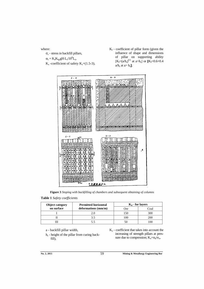
Figure 3 Stoping with backfilling of chambers and subsequent obtaining of columns
Table 1 Safety coefficients
Object category
on surface
Permitted horizontal
deformations (mm/m)
Kd - for layers
Ore Coal
I 2.0 150 300
II 3.5 100 200
III 5.5 50 100
a - backfill pillar width,
hs - height of the pillar from curing back-
fill),
Ko - coefficient that takes into account the increasing of strength pillars at pres-sure due to compression; Ko= k/ o,
No. 2, 2015 Mining & Metallurgy Engineering Bor 60
H - depth of the upper surface of the pi-
llar,
Kh - coefficient that takes into account
the degree of load of backfill pillar
by caved rocks from roofing,
Lp - width of the panel block (chamber)
in the backfill,
Lz - width of the panel of artificial pillars
of backfill.
For the unexplored "in situ" conditions
Kh = 0.5 and for chambers between the pi-
llars of backfill which are not backfilled
Kh = L / h < 1, where L - chamber width
(undermined pillar).
Strength of backfill materials for ensu-
ring the stability of horizontal rooms respec-
tively, projected span of rooms in the fill is
determined by the formula:
e = Kz 0,49 gHz cos (0.95-e-0.06a
)-
1.76 , Pa
Selection of dimensions of chambers and
pillars and their arrangement at excavation,
strength of backfill of chamber and pillar
mining method with storage of ore and sub-
sequent back filling of stopes by curing
backfill, if more horizons are dug, should be
done by equations P and z =f( P). In
them, there will be a change of values
Hz=NhH; Hz- height of backfilled space de-
pends on the N height of excavated horizons
hH. Allowable deformation of backfilling
area P’=( 1+ 2+ 3)N does not depend on
the elastic deformation (10 mm) of roofing
of each horizon 1 incomplete filling of
chambers about 1% 2, and backfill com-
pression due to load 3= ohH, and changes in
vertical stress 1.
1 = K Kv gHs
p’=Hsr/Kd
z = 1’ ln o NHhH / ln P’
Besides the well-known marks Kv -
coefficient which takes the stress change
in the fill, depending on the ratio of ore
body width and the depth of deposit
Kv=(AR/Hs)+0.61; AR- size of ore body by
stretching or declining.
From this formula it is evident that
protection of the earth's surface from de-
formation besides strength of backfill, its
compressibility is an important parameter,
because the strength of backfill on pres-
sure may be less than the vertical stress.
Pri P’= oNhhH ; z= ’.
CONCLUSION
For the known geometry of layer, physi-
cal and mechanical properties of deposit
rocks and accompanying rocks of roofing
and bottom, and objectives to be achieved,
using the chamber pillar mining method
with storage of ore and filling the excavated
chambers after discharge of ore, curing
backfill, in order to obtain the remaining
protective pillars from backfill, according to
Fig. 3. It is possible on the basis of consi-
dered mutual work of deposit rocks and
backfill, in chambers filled, to choose the
best dynamics of deposit excavation, arran-
gement of excavation, backfill material of
adequate strength and compressibility, etc.
REFERENCES
[1] D. M. Broninkov et al., Backfill Works
in the Mines Nedra, Moscow, Russia
1989, p. 146, (In Russian);
[2] V. I. Homyakov, Foreign Experience
Tab in the Mines Nedra, Moscow,
Russia, 1984, p. 143, (In Russian);
[3] V. R. Imenitov, V. F. Abramov, V. V.
Popov, Localization of Emptiness in
the Underground Ore Mining, Nedra,
Moscow, Russin, 1983, p. 72, (In
Russian);
[4] M. Miljković, R. Stanojlović, J. Soko-
lović, Safety and Deformation Cha-
racteristics of Stopping Materials in
Mines, Mining Engineering, Bor,
2(2012), pp. 13-28;
[5] V. Jovičić, M. Miljković, J. Nujić, H.
Uljić, M. Vukić, Security Systems in
Mining Industry, Tuzla, Univerzal,
1987, p. 423.
Broj 2, 2015. Mining & Metallurgy Engineering Bor 61
INSTITUT ZA RUDARSTVO I METALURGIJU BOR ISSN: 2334-8836 (Štampano izdanje)
im proizvodnim sistemima Rudnik bakra Bor i Rudnika bakra Majdan-
pek" i TR 33038 "Usavršavanje tehnologije eksploatacije i prerade rude bakra sa monitoringom
životnog i radnog okruženja u RTB Bor Grupi", koje je finansiralo Ministarstvo za obrazovanje,
nauku i tehnološki razvoj Republike Srbije. Autori se zahvaljuju Ministarstvu za finansijsku podršku.
1. UVOD
Potpuno otkopavanje ležišta mineralne
sirovine bez osiromašenja rude uz očuvanje
ekoloških faktora u eksploatacionom polju
može da se realizuje samo otkopnim meto-
dama sa zapunjavanjem otkopanih prostora
u uzlaznom ili silaznom poretku otko-
pavanja i zapunjavanja [1]. Zavisno od
ciljeva potpunog otkopavanja ležišta sa
zapunjavanjem otkopanih prostora, odre-
đuje se potrebna čvrstoća zasipa i bira se
vrsta zasipnog materijala kojim se ta
čvrstoća može postići [2]. Čvrstoća zasipa
naziva se normativnom ako je moguće
njime obezbediti sigurno držanje potrebnih
otvorenih prostora. To se može postići
primenom očvršćavajućeg zasipa [3].
Potpuno dobijanje ležišta bez osiro-
mašenja rude može se realizovati sledećim
grupama otkopnih metoda [4]:
1. Etažno otkopavanje hodnicima, strmih
rudnih žica i sočiva; a) odozdo na gore,
stajanjem opreme na zasipu, b) odozgo na
dole, ispod zasipa, kada oprema stoji na
čvrstoj steni (rudi).
2. Jednoslojno ili višeslojno otkopava-
nje moćnih rudnih ležišta; a) vertikalno
slojno otkopavanje odozdo na gore, (oprema
se kreće po zasipu), b) horizontalno slojno
Broj 2, 2015. Mining & Metallurgy Engineering Bor 62
otkopavanje odozgo na dole, ispod betonske
ploče (oprema se kreće po čvrstom podu).
3. Podetažno otkopavanje ležišta sa
naknadnim zapunjavanjem otkopa; a)
očvršćavajućim zasipom sa kretanjem
otkopnog fronta odozdo na gore, b) ispod
betonske ploče, sa zapunjavanjem otkopa
očvršćavajućim zasipom (kretanjem otkop-
nog fronta odozgo na dole.
4. Komorno stubno otkopavanje ležišta
sa magazioniranjem rude, zapunjavanjem
otkopa po istakanju rude očvršćavajućim
zasipom i naknadnim dobijanjem zaštitnih
stubova rude u zasipu istom otkopnom
metodom. Tu se može primeniti: a) panelno
i b) unakrsno otkopavanje komora.
U zavisnosti od poretka otkopavanja,
konstrukcije i geometrije otkopa, ciljeva,
troškova primene otkopne metode, fizičko-
mehaničkih karakteristika ležišta i pratećih
stena, kao i dubine ležišta, vrši se odre-
đivanje potrebne čvrstoće zasipa.
2. ODNOSI PRATEĆIH STENA
LEŽIŠTA I ZAPUNJENIH
OTKOPANIH PROSTORA U
LEŽIŠTU
Čvrstoća stvrdnjavajućeg zasipa je zado-
voljavajuća (normativna) ako je moguće
sigurno otvaranje veštačkog, (zasipnog), ma-
siva projektovanim rudničkim prostorijama i
otkopima, i ako obezbeđuje očuvanje zem-
ljine površine i objekata iznad ležišta od
deformacija. Na masiv od zasipnog materi-
jala deluju gravitacione i tektonske (statičke)
i od minerskih radova (dinamičke) sile.
Masa zapunjenog otkopa može biti podvr-
gnuta deformacijama usled pritiska, rasteza-
nja, smicanja, izuvijanja u uslovima jedno-
osnog, dvoosnog i zapreminskog napregnu-
tog stanja. Za izbor i kontrolu potrebne
čvrstoće zasipnog materijala, s obzirom na
uloge koje treba da zadovolji, nezavisno od
karaktera opterećenja, čvrstoća zasipnog
materijala bira se prema potrebnoj čvrstoći
na jednoosni pritisak.
Potrebna čvrstoća zasipnog materijala
određuje se po jednom ili više faktora:
a) stabilnosti (držanja) vertikalnih otvo-
renih bokova
b) horizontalno otvorenih plafona,
c) dopuštenih deformacija zemljine
površine,
d) mogućnosti kretanja opreme po
površini zasipa itd.
Masa od zasipnog materijala i okolne
stene, u određenim uslovima obrazuju slo-
ženi prostorni sistem zasip - stene. Glavni
strukturni elementi takvog sistema - stene
krovine i podine i zasipnog prostora, veoma
se razlikuju.
Proračun potrebne čvrstoće zasipa bazira
se na znanjima o naponsko - deformacionim
karakteristikama prirodnog stenskog i vešta-
čkog, (od zasipa), masiva u zoni otkopa-
vanja, karaktera njihovog uzajamnog delo-
vanja i svodi se na rešavanje triju zadataka.
1. Nalaženja opterećenja na masu
zasipanog otkopa
2. Određivanja napona u zasipu kao
sastavnom elementu sistema stene,
(stena zasipani prostor).
3. Utvrđivanja neophodne čvrstoće
zasipa, koja proističe iz potrebnog
koeficijenta pokazanosti, (sigurno-
sti), za određeno naponsko stanje,
uz uticaj ostalih tehnoloških fak-
tora pri otkopavanju ležišta.
Opterećenje na veštački masiv zasipa u
otkopu zavisi: od fizičko-mehaničkih kara-
kteristika okolnih stena, napona u njima,
geometrije zapunjenog otkopa, (veličine,
dubine i nagiba), i fizičko-mehaničkih kara-
kteristika zasipa, kao i od uloge koju kons-
trukcija od zasipnog materijala ispunjava u
toku dalje eksploatacije i po završetku
eksploatacije ležišta.
Pri potpunom otkopavanju ležišta (otkop
uz predhodni zapunjeni otkop), u krovini
ležišta, u blizini otkopa, obrazuje se zona
smanjenog pritiska (rasterećenja), a u
rudnom masivu ispred fronta napredovanja
Broj 2, 2015. Mining & Metallurgy Engineering Bor 63
otkopa pojavljuje se zona povišenog
oslonačkog pritiska sl. 1. Sa povećanjem
širine otkopanog prostora i zapunjenog
prostora, stene krovine i zasip u zapunjenom
prostoru ponašaju se kao okolne stene i
popustljiva podgrada, dok zasip ne primi
celokupno opterećenje stuba krovinskih
stena. Opterećenje na otkopu potiče od ploče
stena krovine, koja se jednim delom oslanja
na zasipani deo otkopa, a drugim delom na
rudni masiv. Dimenzije zone rasterećenja su
proporcionalne deformacionim karakteristi-
kama zasipa . Deformaciona karakteristika
zasipa zavisi od vrste zasipa i načina ugra-
dnje. Pri 3% pomeranje nalegajućih
stena vrši se povijanjem bez pucanja i
komadanja. Pri 3% u krovini dolazi do
pucanja i raslojavanja stena.
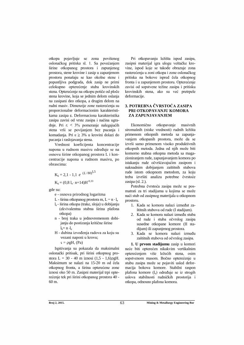
Vrednost koeficijenta koncentracije
napona u rudnom masivu određuje se na
osnovu širine otkopanog prostora L i kon-
centracije napona u rudnom masivu, po
obrascima:
Kk = 2,1 - 1,1 5,1)80/(Le
Kk = (0,8 le n+14)H-0,33
gde su:
e - osnova prirodnog logaritma
L - širina otkopanog prostora m, L = n le
le - širina otkopa (trake, sloja) u dobijanju
(ekvivalentna stubna širina plafona
otkopa)
n - broj traka u jednovremenom dobi-
janju do postizanja kritične širine
lk= n le
H - dubina izvođenja radova za koju su
vezani naponi u krovu;
= gH, (Pa)
Ispitivanja su pokazala da maksimalni
oslonački pritisak, pri širini otkopnog pro-
stora L = 30 - 40 m iznosi (1,5 - 1,6) gH.
Maksimum se nalazi na 15-20 m od čela
otkopnog fronta, a širina opterećene zone
iznosi oko 50 m. Zasipni materijal trpi opte-
rećenje tek pri širini otkopanog prostora 40 -
60 m.
Pri otkopavanju ležišta ispod zasipa,
zasipni materijal igra ulogu veštačke kro-
vine, ispod koje se takođe obrazuje zona
rasterećenja u zoni otkopa i zone oslonačkog
pritiska na bokove ispred čela otkopnog
fronta i u zapunjenom prostoru. Opterećenje
zavisi od sopstvene težine zasipa i pritisku
krovinskih stena, ako su već pretrpele
deformacije.
3. POTREBNA ČVRSTOĆA ZASIPA
PRI OTKOPAVANJU KOMORA
ZA ZAPUNJAVANJEM
Ekonomično otkopavanje masivnih
siromašnih (niske vrednosti) rudnih ležišta
primenom otkopnih metoda sa zapunja-
vanjem otkopanih prostora, može da se
izvrši samo primenom visoko produktivnih
otkopnih metoda. Jedna od njih može biti
komorno stubna otkopna metoda sa maga-
zioniranjem rude, zapunjavanjem komora po
istakanju rude očvršćavajućim zasipom i
naknadnim dobijanjem zaštitnih stubova
rude istom otkopnom metodom, za koju
treba izvršiti analizu potrebne čvrstoće
zasipa (sl. 2.).
Potrebna čvrstoća zasipa može se pos-
matrati za tri stadijuma u kojima se može
naći stub od zasipnog materijala u otkopnom
prostoru.
1. Kada se komora nalazi izmeđut za-
štitnih stubova od rude (I stadijum).
2. Kada se komora nalazi između stuba
od rude i stuba očvrslog zasipa
susedne otkopane komore (II sta-
dijum) ili zapunjenog prostora.
3. Kada se komora nalazi između
zaštitnih stubova od očvrslog zasipa.
1. U prvom stadijumu zasip u komori
neće biti opterećen nikakvim vertikalnim
opterećenjem više ležećih stena, osim
sopstvenom masom. Bočno opterećenje u
stubu zasipa može se pojaviti usled defor-
macija bokova komore. Stabilni raspon
plafona komore (le) određuje se iz strogih
uslova stabilnosti rudničkih prostorija i
otkopa, odnosno plafona komora.
Broj 2, 2015. Mining & Metallurgy Engineering Bor 64
Stabilnost potkopanog plafona prema
ktiričnim deformacijama određuje se iz
uslova.
gr gd
gde su:
gd - dopuštena deformacija plafona, pri
kojoj je plafon komore stabilan.
gr - relativna deformacija plafona ko-
more. Ona se određuje po formuli:
gr = 1/ 1+(HR/le)f
HR - redukovana za uslove monolitnog
masiva, dubina plafona komore
HR=(1-Kg) Hk
Hk - debljina krovine od nanosa na povr-
šini do ravni plafona komore
Kg - koeficijent gubitka stabilnosti pla-
fona zbog raspucalosti i strukturnih
osobina stena (zavisno od RQD ka-
rakteristike). Njegova vrednost mo-
že biti određena na osnovu procen-
ta izvađenog jezgra
Kg = 0,84 + 0,01 Nj - 0,0002 Nj2
gde su:
Nj - procenat izvađenog jezgra (često se
prikazuje visoka vrednost)
f - koeficijent čvrstoće stena po Proto-
djakonovu
le - ekvivalentni stabilni raspon šupljine
(širine) komore
Ekvivalentni stabilni raspon (širina)
komore može biti određen, ako se usvoje
granični uslovi, i formula reši eksplicitno
po le.
g < 0,001 - stabilni raspon komore
g = (0,001-0,04) - stanje između stabil-
nosti i potpunog zarušavanja
g 0,04 - potpuno obrušavanje nalega-
juće krovine
fR
ff
Re
g
gH
g
gHl
11 , (m)
Naponi će se koncentrisati u bokovima
komore prema sl. 1.
Oni se neće prenositi na zasip u komori,
ili čak i više komora, dok šupljina ispod
podkopane krovine ne dostigne kritičan
raspon (govori se o šupljini jer se pri zapu-
njavanju otkopa nikad neće potpuno
poduhvatiti krovina).
lk = Hk f
g
g
1, (m)
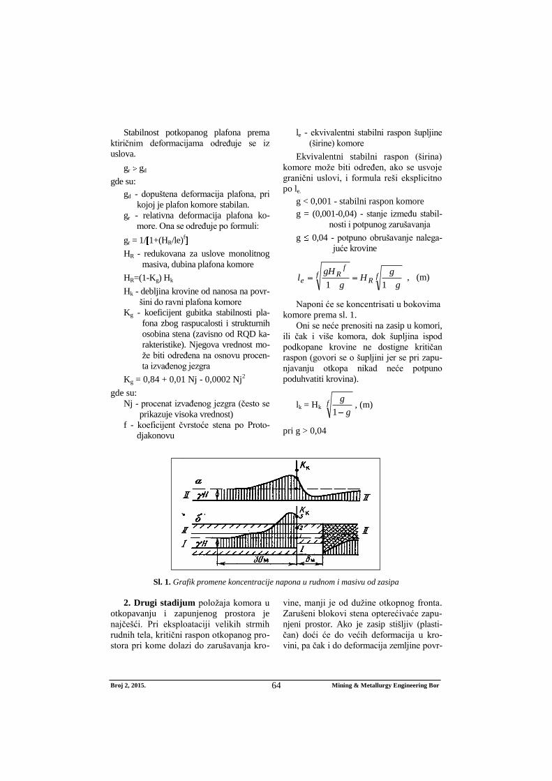
pri g > 0,04
Sl. 1. Grafik promene koncentracije napona u rudnom i masivu od zasipa
2. Drugi stadijum položaja komora u
otkopavanju i zapunjenog prostora je
najčešći. Pri eksploataciji velikih strmih
rudnih tela, kritični raspon otkopanog pro-
stora pri kome dolazi do zarušavanja kro-
vine, manji je od dužine otkopnog fronta.
Zarušeni blokovi stena opterećivaće zapu-
njeni prostor. Ako je zasip stišljiv (plasti-
čan) doći će do većih deformacija u kro-
vini, pa čak i do deformacija zemljine povr-
Broj 2, 2015. Mining & Metallurgy Engineering Bor 65
šine (kod plićih ležišta). Ipak zapunjeni pro-
stor predstavlja zonu rasterećenja. Pri kre-
tanju otkopnog fronta od periferije rudnog
tela, prema prostorijama otvaranja, mogu se
prijaviti sledeći slučajevi rasporeda napona:
a) Iznad prvih otkopanih komora pri širi-
ni otkopanog prostora L = nle < lk (stabilne
ekvivalentne širine) u krovini otkopa
pojavljuju se zatezni naponi, a nabokovima
otkopa i neporemećenih stena koncentrišu se
naponi pritiska, zavisno od širine otkopanog
prostora. Koeficijent koncentracije napona
određuje se po formuli za Kk, pa vertikalni
napon u masivu iznosi:
p=Kk sgH, (Pa)
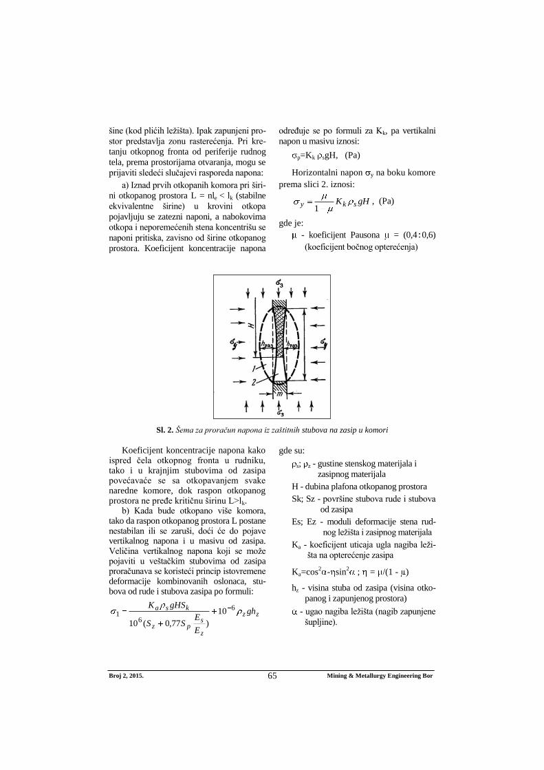
Horizontalni napon y na boku komore
prema slici 2. iznosi:
gHK sky1
, (Pa)
gde je:
- koeficijent Pausona = (0,4 0,6)
(koeficijent bočnog opterećenja)
Sl. 2. Šema za proračun napona iz zaštitnih stubova na zasip u komori
Koeficijent koncentracije napona kako
ispred čela otkopnog fronta u rudniku, tako i u krajnjim stubovima od zasipa povećavaće se sa otkopavanjem svake naredne komore, dok raspon otkopanog prostora ne pređe kritičnu širinu L>lk.
b) Kada bude otkopano više komora, tako da raspon otkopanog prostora L postane nestabilan ili se zaruši, doći će do pojave vertikalnog napona i u masivu od zasipa. Veličina vertikalnog napona koji se može pojaviti u veštačkim stubovima od zasipa proračunava se koristeći princip istovremene deformacije kombinovanih oslonaca, stu-bova od rude i stubova zasipa po formuli:
zz
z
spz
ksa gh
E
ESS
gHSK 6
61 10
)77,0(10
gde su:
s; z - gustine stenskog materijala i
zasipnog materijala
H - dubina plafona otkopanog prostora
Sk; Sz - površine stubova rude i stubova
od zasipa
Es; Ez - moduli deformacije stena rud-
nog ležišta i zasipnog materijala
Ka - koeficijent uticaja ugla nagiba leži-
šta na opterećenje zasipa
Ka=cos2
- sin2
; = /(1 - )
hz - visina stuba od zasipa (visina otko-
panog i zapunjenog prostora)
- ugao nagiba ležišta (nagib zapunjene
šupljine).
Broj 2, 2015. Mining & Metallurgy Engineering Bor 66
Čvrstoća zasipa u otkopanom prostoru
mora biti veća od vertikalnog napona koji
se pojavljuje u zasipu, da ne bi došlo do
popuštanja i sabijanja zasipa i dalje defor-
macije krovine.
z > 1
Kod dubokih tankih ležišta može se
dopustiti i sabijanje zasipa do određene vi-
sine, pri kojoj neće doći do nedopuštenih
deformacija zemljine površine i smanjenja
koeficijenta sigurnosti K 4 .
c) Krajnji slučaj drugog stadijuma
pojavljuje se pri kretanju otkopnog fronta
tako da se dobijanje komora vrši između
masiva rude i masiva zasipa. Krovina se
oslanja na otkopni front rude, sa konzolom
ne oslonjene krovine na zasip dužine l < l ;
l< n le i dela krovine koji je popustio pod
naponom višeležećih masa. Komora u
otkopavanju se nalazi u zoni ispod konzole,
gde su vertikalni naponi smanjeni. Maksi-
malni vertikalni napon se nalazi ispred
otkopnog fronta u rudnom masivu. I za
komore u otkopavanju na rastojanju l < lk
nalazi se zona smanjenog vertikalnog
napona. Na rastojanju L > lk i masiv zasipa
se nalazi pod koncentrisanim vertikalnim
naponom istim kao u rudnom masivu.
Za iznalaženje potrebne čvrstoće zasipa
za očuvanje zemljine površine od defor-
macija potrebno je uzeti u obzir moguće
dopušteno sabijanje zasipa pri kome neće
doći do oštećenja zemljine površine.
Za slepa izolovana ležišta pravilnog
oblika, uticaj dimenzija (visine) otkopanog i
zapunjenog područja na deformaciju (sle-
ganje) zemljine površine u zavisnosti od
kompresionih svojstava zasipa ocenjuje se
na osnovu koeficijenta sigurnosti, čija
vrednost treba da bude veća od dopuštene
prema tabeli 1 [5].
Ks > Kd = H / P
Vertikalna prihvatljiva veličina defor-
macije zasipanog prostora P određuje se po
formuli:
P = o hz (1-e) 1/ z , (m)
gde su:
P - smanjenje visine stuba od zasipa
pod opterećenjem 1, (m)
1 - dejstvojući vertikalni napon, (Pa)
o - deformaciona karakteristika odre-
đene vrste zasipa
hz - debljina (visina) stuba zasipa
z - čvrstoća zasipa na pritisak
Ks - koeficijent sigurnosti kojim se oce-
njuje stabilnost krovine
Iz prethodne formule može se izračunati
potrebna ili dovoljna čvrstoća zasipa z za
tanka duboka ležišta, kod kojih će usled
opterećenja krovine zasip biti preopterećen i
delimično sabijen. Dopušteno sabijanje
zasipa biće P = H/Kd , a potrebna čvrstoća
zasipa z:
)ln(
ln1
P
hzoz , (Pa)
3. Stadijum kada se vrši otkopavanje
zaštitnog stuba ili komore koja se nalazi
između zaštitnih stubova od očvrslog zasipa
(u zasipu) je najopasniji, jer u stubovima
dolazi do koncentracije napona sa obe strane
iz otkopanih prostora. Naponi se sabiraju, a
mogu se proračunati po formulama za p i
y. U pripremnim prostorijama može doći
do ispoljavanja dinamičkih pojava i gorskih
udara. Do gorskih udara neće doći ako stena
stuba nije sklona akumulaciji energije ela-
stične deformacije i ako su koncentrisani
naponi manji od čvrstoće stene na pritisak
p < cs.
Do ispoljavanja gorskih udara neće
doći i ako zasip u zapunjenom prostoru
ima odogovarajuću pritisnu čvrstoću, tako
da može da izvrši ukrućenje stuba rude i
obezbedi stabilnost otkopne komore pri
otkopavanju. Normativa pritisna čvrstoća
zasipa u fazi dobijanja komora između
stubova od zasipnog materijala treba da
iznosi:
of
zsz
KK
K
Broj 2, 2015. Mining & Metallurgy Engineering Bor 67
gde su:
s = KaKh gH Ls/106Lz - napon u stubo-
vima zasipa
Kz - koeficijent sigunosti Kz=(1,5-3)
Kf - koeficijent forme stuba. S obzirom
na uticaj oblika dimenzija stuba na
noseću sposobnost Kf=(a/hs)0,5
pri
a>hs ili Kf=0,6+0,4 a/hs pri a> hs ;
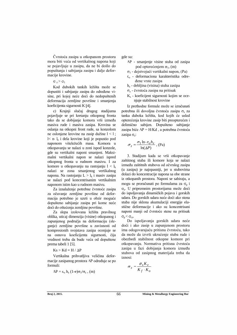
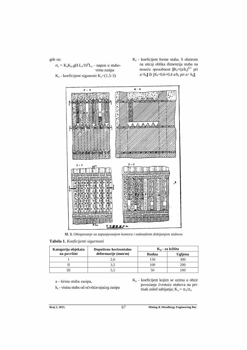
Sl. 3. Otkopavanje sa zapunjavanjem komora i naknadnim dobijanjem stubova
Tabela 1. Koeficijenti sigurnosti
Kategorija objekata
na površini
Dopuštene horizontalne
deformacije (mm/m)
Kd - za ležišta
Rudna Ugljena
I 2,0 150 300
II 3,5 100 200
III 5,5 50 100
a - širina stuba zasipa,
hs - visina stuba od očvršćavajućeg zasipa
Ko - koeficijent kojim se uzima u obzir povećanje čvrstoće stubova na pri-tisak usled sabijanja; Ko = k/ o
Broj 2, 2015. Mining & Metallurgy Engineering Bor 68