34
ENGLISH LCD Projector User Manual FRANÇAIS DEUTSCH ITALIANO ESPAÑOL MODEL X500U X500
EN – 1
EN
GL
ISH
LCDProjectorUser Manual F
RA
NÇ
AIS
DE
UT
SC
HIT
AL
IAN
OE
SP
AÑ
OL
MODEL X500U
X 5 0 0
EN – 2
RISK OF ELECTRIC SHOCKDO NOT OPEN
CAUTION
CAUTION: TO REDUCE THE RISK OF ELECTRIC SHOCK,
DO NOT REMOVE COVER (OR BACK)
NO USER-SERVICEABLE PARTS INSIDE
REFER SERVICING TO QUALIFIED
SERVICE PERSONNEL.
The lightning flash with arrowhead symbol, within an equilateral triangle, is intendedto alert the user to the presence of uninsulated “dangerous voltage” within theproduct’s enclosure that may be of sufficient magnitude to constitute a risk of electricshock.
The exclamation point within an equilateral triangle is intended to alert the user to thepresence of important operating and maintenance (servicing) instructions in the litera-ture accompanying the appliance.
WARNING:TO PREVENT FIRE OR SHOCK HAZARD, DO NOT EXPOSE THIS APPLIANCE TO RAIN OR MOISTURE.
CAUTION:TO PREVENT ELECTRIC SHOCK, DO NOT USE THIS (POLARIZED) PLUG WITH AN EXTENSIONCORD, RECEPTACLE OR OTHER OUTLET UNLESS THE BLADES CAN BE FULLY INSERTED TOPREVENT BLADE EXPOSURE.
NOTE:SINCE THIS PROJECTOR IS PLUGGABLE EQUIPMENT, THE SOCKET-OUTLET SHALL BE IN-STALLED NEAR THE EQUIPMENT AND SHALL BE EASILY ACCESSIBLE.
WARNINGUse the attached specified power supply cord. If youuse another power-supply cord, it may cause interfer-ence with radio and television reception.
Use the attached RGB cable, RS-232C cable with thisequipment so as to keep interference within the limitof a FCC Class A device.
This apparatus must be grounded.
DO NOT LOOK DIRECTLY INTO THE LENSWHEN PROJECTOR IS IN THE POWER ONMODE.
When using the projector in EuropeCOMPLIANCE NOTICEThis LCD - Video Projector complies with therequirements of the EC Directive 89/336/EEC “EMCDirective” as amended by Directive 93/68/EEC and73/23/EEC “Low Voltage Directive” as amended byDirective 93/68/EEC.
The electro-magnetic susceptibility has been chosenat a level that gains proper operation in residentialareas, on business and light industrial premises andon small-scale enterprises, inside as well as outsideof the buildings. All places of operation arecharacterised by their connection to the public lowvoltage power supply system.
WARNINGUse the attached RGB cable or RS-232C cable withthis equipment so as to keep interference within thelimits of a EN55022 Class B. Please followWARNINGS instructions.
EN – 3
EN
GL
ISH
Contents
Important safeguards ...........................................................................4Overview ............................................................................................... 6Using the remote control ......................................................................8
Battery installation ......................................................................................................... 8
Installation ............................................................................................9Basic connections ............................................................................... 10
Projector + AV equipment............................................................................................. 10Projector + DVD player or HDTV decoder ................................................................... 10Projector + personal computer ...................................................................................... 11
Preparing the projector for operation ............................................... 12To operate projector power ON.......................................................... 13Menu operation .................................................................................. 15Picture adjustment............................................................................. 18Advanced feature for presentation .................................................... 20
Expand ........................................................................................................................... 20PinP (Picture in Picture) ............................................................................................... 20Still ................................................................................................................................. 20Mouse remote control .................................................................................................... 21Projecting the data from several computers (Connecting the HUB) .......................... 22
Lamp replacement ............................................................................. 23Maintenance ....................................................................................... 24Troubleshooting .................................................................................. 25Indicators ............................................................................................ 26Specifications ...................................................................................... 27
Kensington Lock ............................................................................................................ 27Connectors ..................................................................................................................... 28Dimensional drawings .................................................................................................. 28What’s included in the box ............................................................................................ 28Replacement part .......................................................................................................... 28Specification of RGB signals in each computer mode of the projector ....................... 29
Trademark, Registered trademarkWindows 98 and Windows 95 are registered trademarks of Microsoft in the U.S. and other countries.Macintosh is registered trademark of Apple Computer Inc.IBM and PS/2 are trademarks or registered trademarks of International Business Machines Corporation.MicroSaver and Kensington are registered trademarks of Kensington Technology Group.Other brand or product names are trademarks or registered trademarks of their respective holders.
EN – 4
Important safeguardsPlease read all these instructions regarding your LCDprojector and retain them for future reference. Followall warnings and instructions marked on the LCD pro-jector.
1. Read instructionsAll the safety and operating instructions shouldbe read before the appliance is operated.
2. Retain instructionsThe safety and operating instructions should beretained for future reference.
3. WarningsAll warnings on the appliance and in the oper-ating instructions should be adhered to.
4. InstructionsAll operating instructions must be followed.
5. CleaningUnplug this projector from the wall outlet be-fore cleaning it. Do not use liquid aerosol clean-ers. Use a damp soft cloth for cleaning.
6. Attachments and equipmentNever add any attachments and/or equipmentwithout the approval of the manufacturer assuch additions may result in the risk of fire, elec-tric shock or other personal injury.
7. Water and moistureDo not use this projector near water or in con-tact with water.
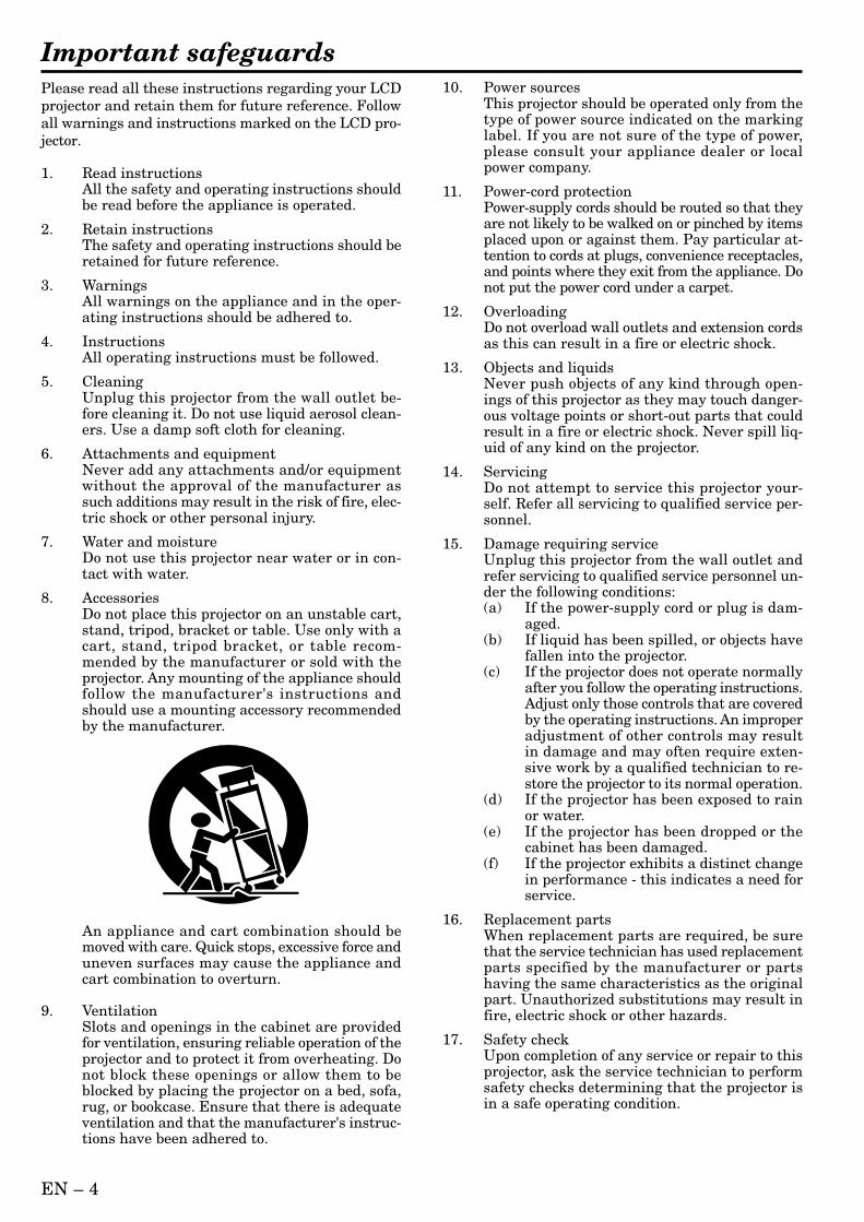
8. AccessoriesDo not place this projector on an unstable cart,stand, tripod, bracket or table. Use only with acart, stand, tripod bracket, or table recom-mended by the manufacturer or sold with theprojector. Any mounting of the appliance shouldfollow the manufacturer's instructions andshould use a mounting accessory recommendedby the manufacturer.
10. Power sourcesThis projector should be operated only from thetype of power source indicated on the markinglabel. If you are not sure of the type of power,please consult your appliance dealer or localpower company.
11. Power-cord protectionPower-supply cords should be routed so that theyare not likely to be walked on or pinched by itemsplaced upon or against them. Pay particular at-tention to cords at plugs, convenience receptacles,and points where they exit from the appliance. Donot put the power cord under a carpet.
12. OverloadingDo not overload wall outlets and extension cordsas this can result in a fire or electric shock.
13. Objects and liquidsNever push objects of any kind through open-ings of this projector as they may touch danger-ous voltage points or short-out parts that couldresult in a fire or electric shock. Never spill liq-uid of any kind on the projector.
14. ServicingDo not attempt to service this projector your-self. Refer all servicing to qualified service per-sonnel.
15. Damage requiring serviceUnplug this projector from the wall outlet andrefer servicing to qualified service personnel un-der the following conditions:(a) If the power-supply cord or plug is dam-
aged.(b) If liquid has been spilled, or objects have
fallen into the projector.(c) If the projector does not operate normally
after you follow the operating instructions.Adjust only those controls that are coveredby the operating instructions. An improperadjustment of other controls may resultin damage and may often require exten-sive work by a qualified technician to re-store the projector to its normal operation.
(d) If the projector has been exposed to rainor water.
(e) If the projector has been dropped or thecabinet has been damaged.
(f) If the projector exhibits a distinct changein performance - this indicates a need forservice.
16. Replacement partsWhen replacement parts are required, be surethat the service technician has used replacementparts specified by the manufacturer or partshaving the same characteristics as the originalpart. Unauthorized substitutions may result infire, electric shock or other hazards.
17. Safety checkUpon completion of any service or repair to thisprojector, ask the service technician to performsafety checks determining that the projector isin a safe operating condition.
An appliance and cart combination should bemoved with care. Quick stops, excessive force anduneven surfaces may cause the appliance andcart combination to overturn.
9. VentilationSlots and openings in the cabinet are providedfor ventilation, ensuring reliable operation of theprojector and to protect it from overheating. Donot block these openings or allow them to beblocked by placing the projector on a bed, sofa,rug, or bookcase. Ensure that there is adequateventilation and that the manufacturer's instruc-tions have been adhered to.
EN – 5
EN
GL
ISH
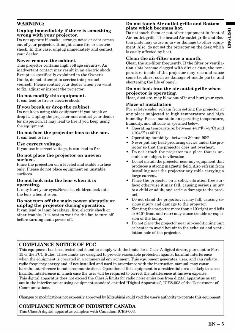
WARNING:Unplug immediately if there is somethingwrong with your projector.Do not operate if smoke, strange noise or odor comesout of your projector. It might cause fire or electricshock. In this case, unplug immediately and contactyour dealer.
Never remove the cabinet.This projector contains high voltage circuitry. Aninadvertent contact may result in an electric shock.Except as specifically explained in the Owner'sGuide, do not attempt to service this productyourself. Please contact your dealer when you wantto fix, adjust or inspect the projector.
Do not modify this equipment.It can lead to fire or electric shock.
If you break or drop the cabinet.Do not keep using this equipment if you break ordrop it. Unplug the projector and contact your dealerfor inspection. It may lead to fire if you keep usingthe equipment.
Do not face the projector lens to the sun.It can lead to fire.
Use correct voltage.If you use incorrect voltage, it can lead to fire.
Do not place the projector on unevensurface.Place the projection on a leveled and stable surfaceonly. Please do not place equipment on unstablesurfaces.
Do not look into the lens when it isoperating.It may hurt your eyes.Never let children look intothe lens when it is on.
Do not turn off the main power abruptly orunplug the projector during operation.It can lead to lamp breakage, fire, electric shock orother trouble. It is best to wait for the fan to turn offbefore turning main power off.
Do not touch Air outlet grille and Bottomplate which becomes hot.Do not touch them or put other equipment in front ofAir outlet grille. The heated Air outlet grille and Bot-tom plate may cause injury or damage to other equip-ment. Also, do not set the projector on the desk whichis easily affected by heat.
Clean the air-filter once a month.Clean the air-filter frequently. If the filter or ventila-tion slots become clogged with dirt or dust, the tem-perature inside of the projector may rise and causesome troubles, such as damage of inside parts, andshortening the life of panel.
Do not look into the air outlet grille whenprojector is operating.Heat, dust etc. may blow out of it and hurt your eyes.
Place of installationFor safety’s sake, refrain from setting the projector atany place subjected to high temperature and highhumidity. Please maintain an operating temperature,humidity, and altitude as specified below.• Operating temperature: between +41°F (+5°C) and
+104°F (+40°C)• Operating humidity: between 30 and 90%• Never put any heat-producing device under the pro-
jector so that the projector does not overheat.• Do not attach the projector to a place that is un-
stable or subject to vibration.• Do not install the projector near any equipment that
produces a strong magnetic field. Also refrain frominstalling near the projector any cable carrying alarge current.
• Place the projector on a solid, vibration free sur-face: otherwise it may fall, causing serious injuryto a child or adult, and serious damage to the prod-uct.
• Do not stand the projector: it may fall, causing se-rious injury and damage to the projector.
• Slanting the projector more than ±10˚(right and left)or ±15˚(front and rear) may cause trouble or explo-sion of the lamp.
• Do not place the projector near air-conditioning unitor heater to avoid hot air to the exhaust and venti-lation hole of the projector.
COMPLIANCE NOTICE OF FCCThis equipment has been tested and found to comply with the limits for a Class A digital device, pursuant to Part15 of the FCC Rules. These limits are designed to provide reasonable protection against harmful interferencewhen the equipment is operated in a commercial environment. This equipment generates, uses, and can radiateradio frequency energy and, if not installed and used in accordance with the instruction manual, may causeharmful interference to radio communications. Operation of this equipment in a residential area is likely to causeharmful interference in which case the user will be required to correct the interference at his own expense.This digital apparatus does not exceed the Class A limits for radio noise emissions from digital apparatus as setout in the interference-causing equipment standard entitled “Digital Apparatus”, ICES-003 of the Department ofCommunications.
Changes or modifications not expressly approved by Mitsubishi could void the user's authority to operate this equipment.
COMPLIANCE NOTICE OF INDUSTRY CANADAThis Class A digital apparatus complies with Canadian ICES-003.
EN – 6
Overview
LAMP
VOLUME
ZOOM/FOCUS
KEYSTONE
TEMP
VIDEOCOMPUTER
MUTEAUTO
POSITION
MENU ENTER
12
1011
9
87
6
1
2
3
4
5
15 14 13
59 7 68
1 2 3 4
10 11 12
REMOTE
AUDIO 2 INCOMPUTER 2 IN
AUDIO OUTCOMPUTER OUT
AUDIO 1 INCOMPUTER 1 IN
DIGITALANALOG
INPUT SELECT
MAIN
AC IN
O I
L
R
S-VIDEOVIDEO
AUDIO
VIDEO 1 IN VIDEO 2 IN
USBRS-232C
X1 X2 X3 X4 II5/X5
5 6 7 983 4
1
2
10111213141516
17
18
Control panel
Terminal board
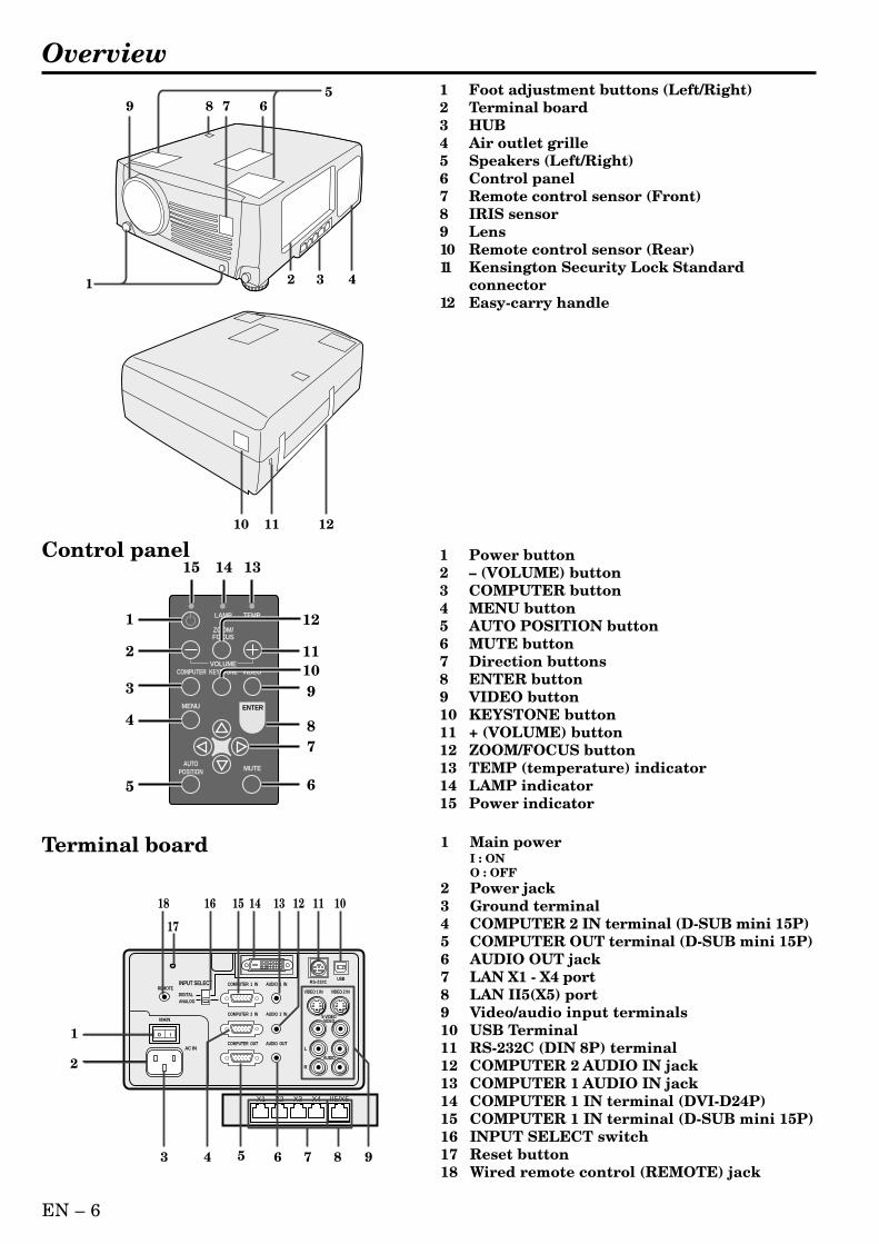
1 Foot adjustment buttons (Left/Right)2 Terminal board3 HUB4 Air outlet grille5 Speakers (Left/Right)6 Control panel7 Remote control sensor (Front)8 IRIS sensor9 Lens10 Remote control sensor (Rear)11 Kensington Security Lock Standard
connector12 Easy-carry handle
1 Power button2 – (VOLUME) button3 COMPUTER button4 MENU button5 AUTO POSITION button6 MUTE button7 Direction buttons8 ENTER button9 VIDEO button10 KEYSTONE button11 + (VOLUME) button12 ZOOM/FOCUS button13 TEMP (temperature) indicator14 LAMP indicator15 Power indicator
1 Main powerI : ONO : OFF
2 Power jack3 Ground terminal4 COMPUTER 2 IN terminal (D-SUB mini 15P)5 COMPUTER OUT terminal (D-SUB mini 15P)6 AUDIO OUT jack7 LAN X1 - X4 port8 LAN II5(X5) port9 Video/audio input terminals10 USB Terminal11 RS-232C (DIN 8P) terminal12 COMPUTER 2 AUDIO IN jack13 COMPUTER 1 AUDIO IN jack14 COMPUTER 1 IN terminal (DVI-D24P)15 COMPUTER 1 IN terminal (D-SUB mini 15P)16 INPUT SELECT switch17 Reset button18 Wired remote control (REMOTE) jack
EN – 7
EN
GL
ISH
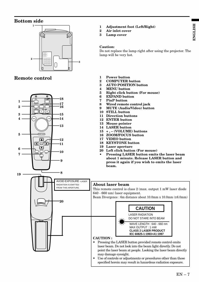
Bottom side1
23
1 Adjustment foot (Left/Right)2 Air inlet cover3 Lamp cover
Caution:Do not replace the lamp right after using the projector. Thelamp will be very hot.
ENTER
RIGHT CLICK
LASER
COMPUTER VIDEO ZOOM/FOCUS
KEYSTONE
VOLMEAUTO
POSITION
MENU
P in P
MUTE
EXPAND STILL
1
2
34
5
6
7
1718
16
1514
13
12
10
20
19
11
9
8
Remote control 1 Power button2 COMPUTER button3 AUTO POSITION button4 MENU button5 Right click button (For mouse)6 EXPAND button7 PinP button8 Wired remote control jack9 MUTE (Audio/Video) button10 STILL button11 Direction buttons12 ENTER button13 Mouse pointer14 LASER button15 + , – (VOLUME) buttons16 ZOOM/FOCUS button17 VIDEO button18 KEYSTONE button19 Laser aperture20 Left click button (For mouse)• Pressing LASER button emits the laser beam
about 1 minute. Release LASER button andpress it again if you wish to emits the laserbeam.
About laser beamThis remote control is class 2 (max. output 1 mW laser diode640 - 660 nm) laser equipment.Beam Divergence : 6m distance about 10.0mm x 10.0mm (±6.0mm)
LASER RADIATIONDO NOT STARE INTO BEAM
WAVE LENGTH : 640 - 660 nmMAX OUTPUT : 1 mWCLASS 2 LASER PRODUCTIEC 60825-1:1993+A1:1997
CAUTION
CAUTION :• Pressing the LASER button provided remote control emits
laser beam. Do not look into the beam light directly. Do notpoint the laser beam at people. Looking the laser beam directlymay damage eyesight.
• Use of controls or adjustments or procedures other than thosespecified herein may result in hazardous radiation exposure.
AVOID EXPOSURE -LASER
RADIATION IS EMITTED
FROM THIS APERTURE.
EN – 8
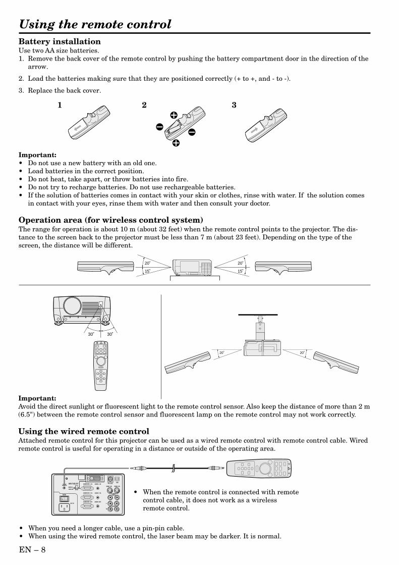
Battery installationUse two AA size batteries.1. Remove the back cover of the remote control by pushing the battery compartment door in the direction of the
arrow.
2. Load the batteries making sure that they are positioned correctly (+ to +, and - to -).
3. Replace the back cover.
Important:• Do not use a new battery with an old one.• Load batteries in the correct position.• Do not heat, take apart, or throw batteries into fire.• Do not try to recharge batteries. Do not use rechargeable batteries.• If the solution of batteries comes in contact with your skin or clothes, rinse with water. If the solution comes
in contact with your eyes, rinse them with water and then consult your doctor.
Operation area (for wireless control system)The range for operation is about 10 m (about 32 feet) when the remote control points to the projector. The dis-tance to the screen back to the projector must be less than 7 m (about 23 feet). Depending on the type of thescreen, the distance will be different.
Important:Avoid the direct sunlight or fluorescent light to the remote control sensor. Also keep the distance of more than 2 m(6.5") between the remote control sensor and fluorescent lamp on the remote control may not work correctly.
Using the wired remote controlAttached remote control for this projector can be used as a wired remote control with remote control cable. Wiredremote control is useful for operating in a distance or outside of the operating area.
20˚
15˚
20˚
15˚
30˚30˚
20˚ 20˚
1 2 3
REMOTE
AUDIO 2 INCOMPUTER 2 IN
AUDIO OUTCOMPUTER OUT
AUDIO 1 INCOMPUTER 1 IN
DIGITALANALOG
INPUT SELECT
MAIN
AC IN
O I
L
R
S-VIDEOVIDEO
AUDIO
VIDEO 1 IN VIDEO 2 IN
USBRS-232C
• When the remote control is connected with remotecontrol cable, it does not work as a wirelessremote control.
• When you need a longer cable, use a pin-pin cable.• When using the wired remote control, the laser beam may be darker. It is normal.
Using the remote control
´ EN – 9
EN
GL
ISH
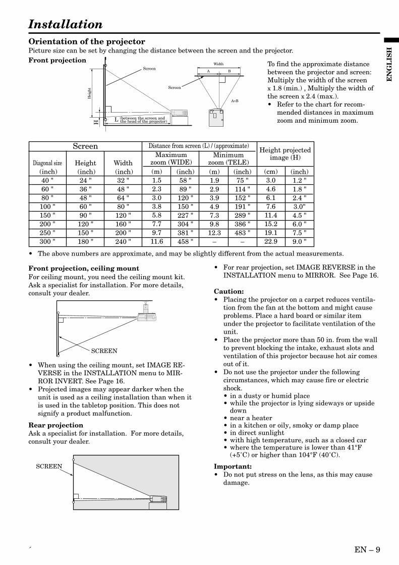
InstallationOrientation of the projectorPicture size can be set by changing the distance between the screen and the projector.Front projection To find the approximate distance
between the projector and screen:Multiply the width of the screenx 1.8 (min.) , Multiply the width ofthe screen x 2.4 (max.).• Refer to the chart for recom-
mended distances in maximumzoom and minimum zoom.
SCREEN
Front projection, ceiling mountFor ceiling mount, you need the ceiling mount kit.Ask a specialist for installation. For more details,consult your dealer.
• When using the ceiling mount, set IMAGE RE-VERSE in the INSTALLATION menu to MIR-ROR INVERT. See Page 16.
• Projected images may appear darker when theunit is used as a ceiling installation than when itis used in the tabletop position. This does notsignify a product malfunction.
Rear projectionAsk a specialist for installation. For more details,consult your dealer.
SCREEN
• For rear projection, set IMAGE REVERSE in theINSTALLATION menu to MIRROR. See Page 16.
Caution:• Placing the projector on a carpet reduces ventila-
tion from the fan at the bottom and might causeproblems. Place a hard board or similar itemunder the projector to facilitate ventilation of theunit.
• Place the projector more than 50 in. from the wallto prevent blocking the intake, exhaust slots andventilation of this projector because hot air comesout of it.
• Do not use the projector under the followingcircumstances, which may cause fire or electricshock.• in a dusty or humid place• while the projector is lying sideways or upside
down• near a heater• in a kitchen or oily, smoky or damp place• in direct sunlight• with high temperature, such as a closed car• where the temperature is lower than 41°F
(+5˚C) or higher than 104°F (40˚C).
Important:• Do not put stress on the lens, as this may cause
damage.
L (between the screen and the head of the projector)
Screen
Screen
Width
Hei
ght
H
A
A=B
B
• The above numbers are approximate, and may be slightly different from the actual measurements.
Diagonal size (inch)
40 "60 "80 "100 "150 "200 "250 "300 "
Height (inch)
24 "36 "48 "60 "90 "
120 "150 "180 "
Width (inch)
32 "48 "64 "80 "120 "160 "200 "240 "
Screen Distance from screen (L) / (approximate)Maximum
zoom (WIDE)(cm)3.04.66.17.611.415.219.122.9
(inch)1.2 "1.8 "2.4 "3.0"4.5 "6.0 "7.5 "9.0 "
Minimumzoom (TELE)
Height projectedimage (H)
(m)1.52.33.03.85.87.79.711.6
(m)1.92.93.94.97.39.812.3
–
(inch)58 "89 "120 "150 "227 "304 "381 "458 "
(inch)75 "114 "152 "191 "289 "386 "483 "
–
EN – 10
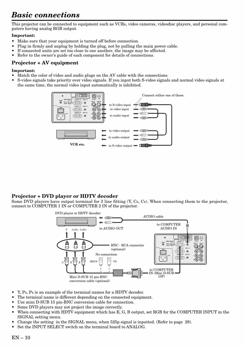
Basic connectionsThis projector can be connected to equipment such as VCRs, video cameras, videodisc players, and personal com-puters having analog RGB output.
Important:• Make sure that your equipment is turned off before connection.• Plug in firmly and unplug by holding the plug, not by pulling the main power cable.• If connected units are set too close to one another, the image may be affected.• Refer to the owner's guide of each component for details of connections.
Projector + AV equipmentImportant:• Match the color of video and audio plugs on the AV cable with the connections.• S-video signals take priority over video signals. If you input both S-video signals and normal video signals at
the same time, the normal video input automatically is inhibited.
REMOTE
AUDIO 2 INCOMPUTER 2 IN
AUDIO OUTCOMPUTER OUT
AUDIO 1 INCOMPUTER 1 IN
DIGITALANALOG
INPUT SELECT
MAIN
AC IN
O I
L
R
S-VIDEOVIDEO
AUDIO
VIDEO 1 IN VIDEO 2 IN
USBRS-232C
Connect either one of these.
to S-video input
to S-video output
to video input
to audio input
to video output
to audio output
VCR etc.
REMOTE
AUDIO 2 INCOMPUTER 2 IN
AUDIO OUTCOMPUTER OUT
AUDIO 1 INCOMPUTER 1 IN
DIGITALANALOG
INPUT SELECT
MAIN
AC IN
O I
L
R
S-VIDEOVIDEO
AUDIO
VIDEO 1 IN VIDEO 2 IN
USBRS-232C
B G R
CB(PB)Y CR(PR)
HD/CS VD
DVD player or HDTV decoder
No connection
BNC - RCA connector (optional)
Mini D-SUB 15 pin-BNCconversion cable (optional)
to COMPUTER AUDIO IN to AUDIO OUT
AUDIO cable
to COMPUTER IN (Mini D-SUB
15P)
Projector + DVD player or HDTV decoderSome DVD players have output terminal for 3 line fitting (Y, CB, CR). When connecting them to the projector,connect to COMPUTER 1 IN or COMPUTER 2 IN of the projector.
• Y, PB, PR is an example of the terminal names for a HDTV decoder.• The terminal name is different depending on the connected equipment.• Use mini D-SUB 15 pin-BNC conversion cable for connection.• Some DVD players may not project the image correctly.• When connecting with HDTV equipment which has R, G, B output, set RGB for the COMPUTER INPUT in the
SIGNAL setting menu.• Change the setting in the SIGNAL menu, when 525p signal is inputted. (Refer to page 29).• Set the INPUT SELECT switch on the terminal board to ANALOG.
´ EN – 11
EN
GL
ISH
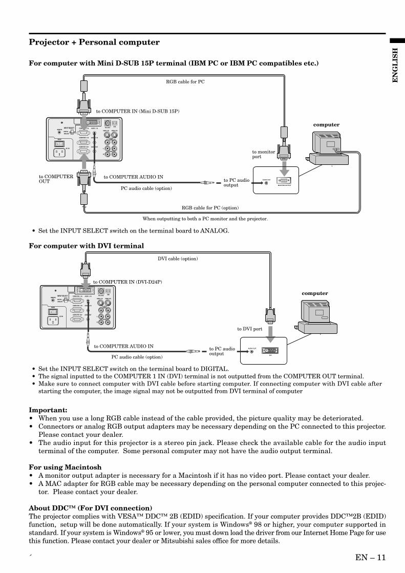
For computer with Mini D-SUB 15P terminal (IBM PC or IBM PC compatibles etc.)
REMOTE
AUDIO 2 INCOMPUTER 2 IN
AUDIO OUTCOMPUTER OUT
AUDIO 1 INCOMPUTER 1 IN
DIGITALANALOG
INPUT SELECT
MAIN
AC IN
O I
L
R
S-VIDEOVIDEO
AUDIO
VIDEO 1 IN VIDEO 2 IN
USBRS-232C
AUDIO OUT
MONITOR OUTPUT
to COMPUTER IN (Mini D-SUB 15P)
to COMPUTER AUDIO IN
to monitorport
to COMPUTER OUT to PC audio
outputPC audio cable (option)
When outputting to both a PC monitor and the projector.
RGB cable for PC
RGB cable for PC (option)
computer
• Set the INPUT SELECT switch on the terminal board to ANALOG.
For computer with DVI terminal
REMOTE
AUDIO 2 INCOMPUTER 2 IN
AUDIO OUTCOMPUTER OUT
AUDIO 1 INCOMPUTER 1 IN
DIGITALANALOG
INPUT SELECT
MAIN
AC IN
O I
L
R
S-VIDEOVIDEO
AUDIO
VIDEO 1 IN VIDEO 2 IN
USBRS-232C
DVI
to COMPUTER IN (DVI-D24P)
DVI cable (option)
to COMPUTER AUDIO IN
to DVI port
PC audio cable (option)
computer
AUDIO OUTto PC audio output
Projector + Personal computer
• Set the INPUT SELECT switch on the terminal board to DIGITAL.• The signal inputted to the COMPUTER 1 IN (DVI) terminal is not outputted from the COMPUTER OUT terminal.• Make sure to connect computer with DVI cable before starting computer. If connecting computer with DVI cable after
starting the computer, the image signal may not be outputted from DVI terminal of computer
Important:• When you use a long RGB cable instead of the cable provided, the picture quality may be deteriorated.• Connectors or analog RGB output adapters may be necessary depending on the PC connected to this projector.
Please contact your dealer.• The audio input for this projector is a stereo pin jack. Please check the available cable for the audio input
terminal of the computer. Some personal computer may not have the audio output terminal.
For using Macintosh• A monitor output adapter is necessary for a Macintosh if it has no video port. Please contact your dealer.• A MAC adapter for RGB cable may be necessary depending on the personal computer connected to this projec-
tor. Please contact your dealer.
About DDC™ (For DVI connection)The projector complies with VESA™ DDC™ 2B (EDID) specification. If your computer provides DDC™2B (EDID)function, setup will be done automatically. If your system is Windows® 98 or higher, your computer supported instandard. If your system is Windows® 95 or lower, you must down load the driver from our Internet Home Page for usethis function. Please contact your dealer or Mitsubishi sales office for more details.
EN – 12
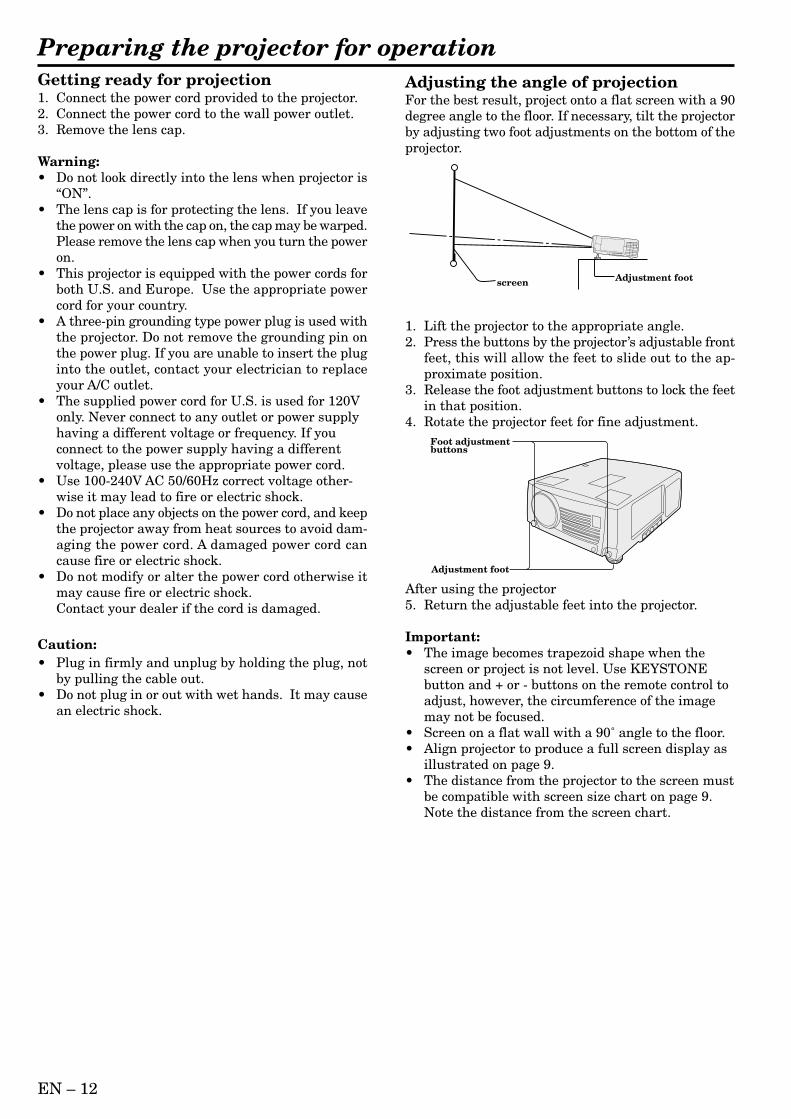
Adjustment footscreen
Preparing the projector for operationGetting ready for projection1. Connect the power cord provided to the projector.2. Connect the power cord to the wall power outlet.3. Remove the lens cap.
Warning:• Do not look directly into the lens when projector is
“ON”.• The lens cap is for protecting the lens. If you leave
the power on with the cap on, the cap may be warped.Please remove the lens cap when you turn the poweron.
• This projector is equipped with the power cords forboth U.S. and Europe. Use the appropriate powercord for your country.
• A three-pin grounding type power plug is used withthe projector. Do not remove the grounding pin onthe power plug. If you are unable to insert the pluginto the outlet, contact your electrician to replaceyour A/C outlet.
• The supplied power cord for U.S. is used for 120Vonly. Never connect to any outlet or power supplyhaving a different voltage or frequency. If youconnect to the power supply having a differentvoltage, please use the appropriate power cord.
• Use 100-240V AC 50/60Hz correct voltage other-wise it may lead to fire or electric shock.
• Do not place any objects on the power cord, and keepthe projector away from heat sources to avoid dam-aging the power cord. A damaged power cord cancause fire or electric shock.
• Do not modify or alter the power cord otherwise itmay cause fire or electric shock.Contact your dealer if the cord is damaged.
Caution:• Plug in firmly and unplug by holding the plug, not
by pulling the cable out.• Do not plug in or out with wet hands. It may cause
an electric shock.
Adjusting the angle of projectionFor the best result, project onto a flat screen with a 90degree angle to the floor. If necessary, tilt the projectorby adjusting two foot adjustments on the bottom of theprojector.
1. Lift the projector to the appropriate angle.2. Press the buttons by the projector’s adjustable front
feet, this will allow the feet to slide out to the ap-proximate position.
3. Release the foot adjustment buttons to lock the feetin that position.
4. Rotate the projector feet for fine adjustment.
After using the projector5. Return the adjustable feet into the projector.
Important:• The image becomes trapezoid shape when the
screen or project is not level. Use KEYSTONEbutton and + or - buttons on the remote control toadjust, however, the circumference of the imagemay not be focused.
• Screen on a flat wall with a 90˚ angle to the floor.• Align projector to produce a full screen display as
illustrated on page 9.• The distance from the projector to the screen must
be compatible with screen size chart on page 9.Note the distance from the screen chart.
Adjustment foot
Foot adjustment buttons
´ EN – 13
EN
GL
ISH
To operate projector power ON
• When the lamp indicator is blinking red, the ser-vice life of the lamp is about to end. Replace thelamp. See pages 23 and 26.
• The picture might not be of optimum performancein extreme hot or cold conditions. (The projector isnot malfunctioning.)
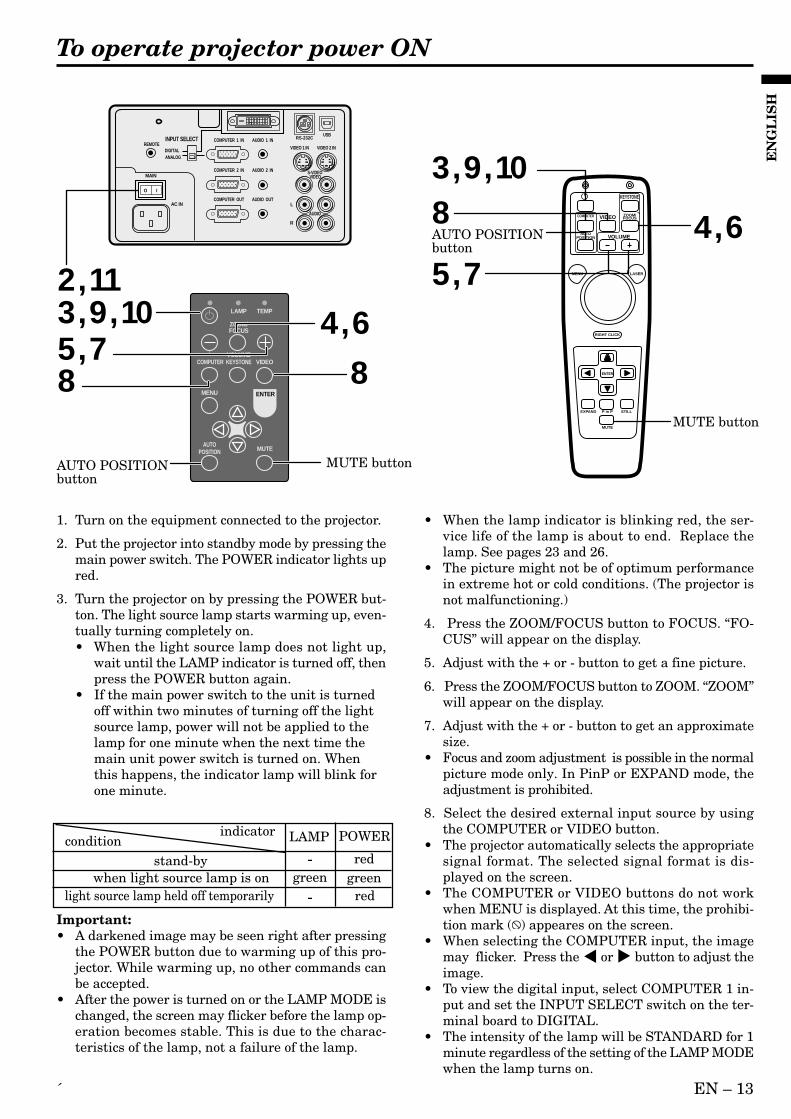
4. Press the ZOOM/FOCUS button to FOCUS. “FO-CUS” will appear on the display.
5. Adjust with the + or - button to get a fine picture.
6. Press the ZOOM/FOCUS button to ZOOM. “ZOOM”will appear on the display.
7. Adjust with the + or - button to get an approximatesize.
• Focus and zoom adjustment is possible in the normalpicture mode only. In PinP or EXPAND mode, theadjustment is prohibited.
8. Select the desired external input source by usingthe COMPUTER or VIDEO button.
• The projector automatically selects the appropriatesignal format. The selected signal format is dis-played on the screen.
• The COMPUTER or VIDEO buttons do not workwhen MENU is displayed. At this time, the prohibi-tion mark ( ) appeares on the screen.
• When selecting the COMPUTER input, the imagemay flicker. Press the $ or % button to adjust theimage.
• To view the digital input, select COMPUTER 1 in-put and set the INPUT SELECT switch on the ter-minal board to DIGITAL.
• The intensity of the lamp will be STANDARD for 1minute regardless of the setting of the LAMP MODEwhen the lamp turns on.
1. Turn on the equipment connected to the projector.
2. Put the projector into standby mode by pressing themain power switch. The POWER indicator lights upred.
3. Turn the projector on by pressing the POWER but-ton. The light source lamp starts warming up, even-tually turning completely on.• When the light source lamp does not light up,
wait until the LAMP indicator is turned off, thenpress the POWER button again.
• If the main power switch to the unit is turnedoff within two minutes of turning off the lightsource lamp, power will not be applied to thelamp for one minute when the next time themain unit power switch is turned on. Whenthis happens, the indicator lamp will blink forone minute.
conditionindicator LAMP POWER
stand-by - redwhen light source lamp is on green green
light source lamp held off temporarily red-Important:• A darkened image may be seen right after pressing
the POWER button due to warming up of this pro-jector. While warming up, no other commands canbe accepted.
• After the power is turned on or the LAMP MODE ischanged, the screen may flicker before the lamp op-eration becomes stable. This is due to the charac-teristics of the lamp, not a failure of the lamp.
LAMP
VOLUME
ZOOM/FOCUS
KEYSTONE
TEMP
VIDEOCOMPUTER
MUTEAUTO
POSITION
MENU ENTER
AUTO POSITIONbutton
AUTO POSITIONbutton
MUTE button
MUTE button
ENTER
RIGHT CLICK
LASER
COMPUTER VIDEO ZOOM/FOCUS
KEYSTONE
VOLUMEAUTO
POSITION
MENU
P in P
MUTE
EXPAND STILL
2 , 11
REMOTE
AUDIO 2 INCOMPUTER 2 IN
AUDIO OUTCOMPUTER OUT
AUDIO 1 INCOMPUTER 1 IN
DIGITALANALOG
INPUT SELECT
MAIN
AC IN
O I
L
R
S-VIDEOVIDEO
AUDIO
VIDEO 1 IN VIDEO 2 IN
USBRS-232C
3 , 9 , 10
3 , 9 , 10
8 8
8
4 , 6
4 , 6
5 , 7
5 , 7

EN – 14
AUDIO 15
To operate projector power ON (Continue)
Turning off the projector9. Press the POWER button.
The message “POWER OFF? YES : PRESS AGAIN”appears on the screen.• To exit from this mode, press any button except
POWER, LASER, mouse pointer, R/L-click,STILL and VOLUME + and - buttons.
10.Press the POWER button again.The light source lamp will be turned off.Pressing the POWER button second time will shutoff the light source lamp, but the exhaust fan con-tinues to operate for 120 seconds to cool down thelight source lamp and LCD panels. In this time, thelamp indicator will be turned off.
11.Turn off the main power switch. When turning offthe main switch, the POWER indicator turns off.
• In cases where the main power switch is acciden-tally turned off when either the intake/exhaustfan or the power source lamp is in operation, allowthe unit to cool down for 10 minutes with thepower turned off. Repeat step 3 when turning onthe power source lamp. If the lamp does not turnon immediately, repeat this step two or threetimes. Replace the lamp if it should still fail toturn on.
AUTO POSITION buttonWhen the source is selected to COMPUTER and theimage is not in the right place, follow as shown below.1. Set screen to the brightest display as possible
(e.g., full-screen display of the “Trash” window).2. If the screen saver is running, turn off the screen saver.3. Press the AUTO POSITION button.• If the image is still not in the right place, adjust
the image position by using the SIGNAL menu.
The volume from the speakerPress the volume + or – button to change the volumefrom the speaker.The volume control bar will appear on the screen.
• The volume control bar will disappear about 10seconds after releasing the volume buttons.
• The volume buttons do not work when MENUselection bar or MENU is displayed.
• If the high level of audio signal, for example DVDis supplied into COMPUTER AUDIO IN terminal,the speaker out may be distorted.
AV muteImage and audio are temporarily muted by pressingthe MUTE button. To restore the image and audio tothe normal mode, press the MUTE button again.• The audio from the AUDIO OUT jack is also muted
by pressing the MUTE button.
Caution:• When you have finished using this equipment, wait
120 seconds for the exhaust fans to stop. Then turnoff the main switch and unplug the power cable fromthe wall outlet, for safety purposes.
• After the lamp is turned off, the lamp cannot beswitched on again for 60 seconds as a precaution-ary measure. It will take another 60 seconds beforethe lamp indicator goes off. If you wish to turn onthe projector again, wait until the indicator is offthen press the POWER button.
• The exhaust fan rotates faster when the tempera-ture around the projector rises.
• When the temperature around the projector becomestoo high, the sign “TEMP!!” blinks red on the screen.If the temperature stays too high, the lamp will beshut off automatically .
EN – 15
EN
GL
ISH
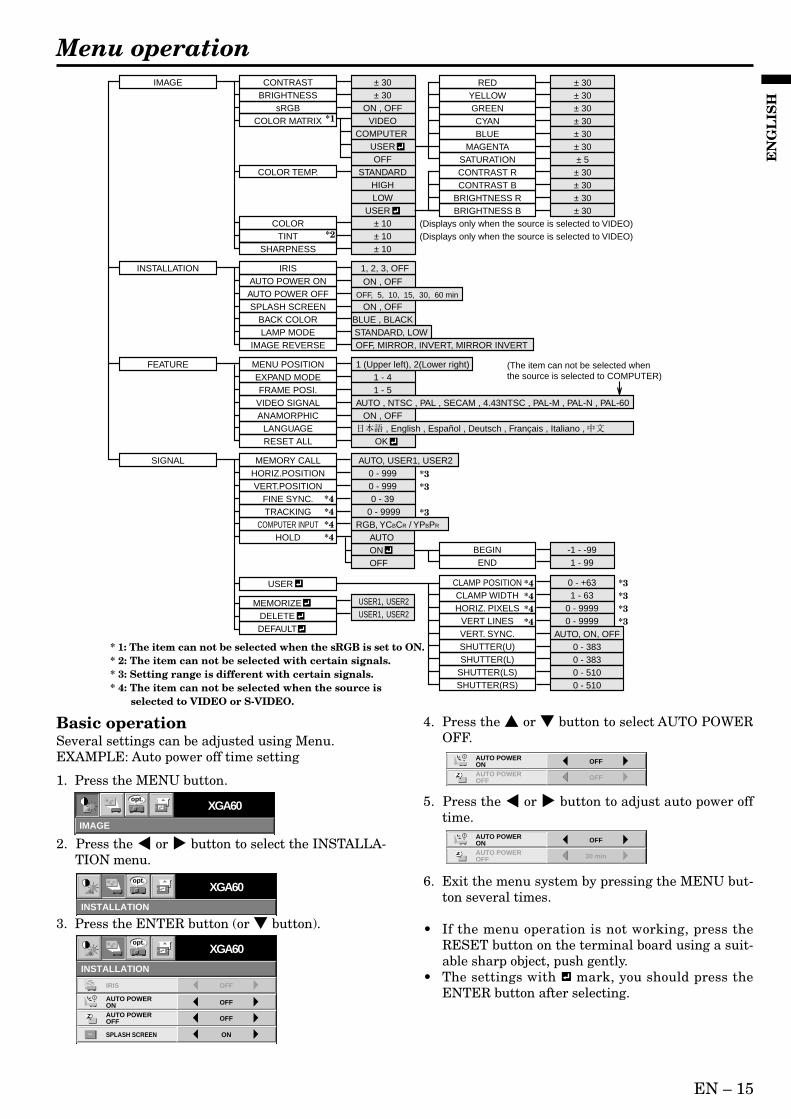
Basic operationSeveral settings can be adjusted using Menu.EXAMPLE: Auto power off time setting
1. Press the MENU button.
2. Press the $ or % button to select the INSTALLA-TION menu.
3. Press the ENTER button (or button).
4. Press the or button to select AUTO POWEROFF.
5. Press the $ or % button to adjust auto power offtime.
6. Exit the menu system by pressing the MENU but-ton several times.
• If the menu operation is not working, press theRESET button on the terminal board using a suit-able sharp object, push gently.
• The settings with mark, you should press theENTER button after selecting.
Menu operation
IMAGE
XGA60opt.
INSTALLATION
XGA60opt.
OFF
AUTO POWER ON OFF
AUTO POWER OFF
IRIS OFF
ON
INSTALLATION
ON
XGA60
SPLASH SCREEN
opt.
OFF
AUTO POWER ON OFF
AUTO POWER OFF
30 min
AUTO POWER ON OFF
AUTO POWER OFF
IMAGE CONTRAST ± 30BRIGHTNESS
COLOR MATRIX
± 30sRGB ON , OFF
STANDARDHIGHLOW
USER
COLOR TEMP.
COLOR ± 10TINT ± 10
SHARPNESS ± 10
CONTRAST R ± 30CONTRAST B ± 30
BRIGHTNESS R ± 30BRIGHTNESS B
(Displays only when the source is selected to VIDEO)(Displays only when the source is selected to VIDEO)
± 30
EXPAND MODE 1 - 4FRAME POSI. 1 - 5
INSTALLATION
IMAGE REVERSE OFF, MIRROR, INVERT, MIRROR INVERT
IRISAUTO POWER ON ON , OFF
RESET ALL OK
AUTO POWER OFFON , OFF
FEATURE MENU POSITION 1 (Upper left), 2(Lower right)
SPLASH SCREENBLUE , BLACKBACK COLORSTANDARD, LOWLAMP MODE
ON , OFFANAMORPHICVIDEO SIGNAL AUTO , NTSC , PAL , SECAM , 4.43NTSC , PAL-M , PAL-N , PAL-60
LANGUAGE , English , Español , Deutsch , Français , Italiano ,
VIDEO
RED ± 30
CYAN ± 30GREEN ± 30
YELLOW ± 30
BLUE ± 30MAGENTA ± 30
SATURATION ± 5
COMPUTER USEROFF
SIGNAL MEMORY CALL AUTO, USER1, USER2HORIZ.POSITION 0 - 999VERT.POSITION 0 - 999
FINE SYNC. 0 - 39TRACKING
USER
0 - 9999
CLAMP POSITION 0 - +63CLAMP WIDTH 1 - 63HORIZ. PIXELS 0 - 9999
VERT LINES 0 - 9999
SHUTTER(L) 0 - 383SHUTTER(U) 0 - 383
SHUTTER(RS) 0 - 510SHUTTER(LS) 0 - 510
VERT. SYNC. AUTO, ON, OFF
MEMORIZE
*3
*4*4*4*4
*4*4*4*4
*3
*3
HOLD AUTO
USER1, USER2
DELETE USER1, USER2
DEFAULT
ON BEGIN -1 - -99END 1 - 99OFF
COMPUTER INPUT RGB, YCBCR / YPBPR
*3*3*3*3
OFF, 5, 10, 15, 30, 60 min
1, 2, 3, OFF
(The item can not be selected when the source is selected to COMPUTER)
*1
*2
* 1: The item can not be selected when the sRGB is set to ON.* 2: The item can not be selected with certain signals.* 3: Setting range is different with certain signals.* 4: The item can not be selected when the source is selected to VIDEO or S-VIDEO.
EN – 16
IMAGE REVERSE
OFF
AUTO POWER ON OFF
AUTO POWER OFF
IRIS OFF
ON
INSTALLATION
ON
STANDARD
BACK COLOR
OFF
BLUE
XGA60
LAMP MODE
SPLASH SCREEN
opt.
XGA60
MENU POSITION
VIDEO SIGNAL AUTO
LANGUAGE English
RESET ALL OK
ANAMORPHIC OFF
AË
?
EXPAND MODE 1.
FRAME POSI.AA
AA
1.
3.
FEATURE
opt.
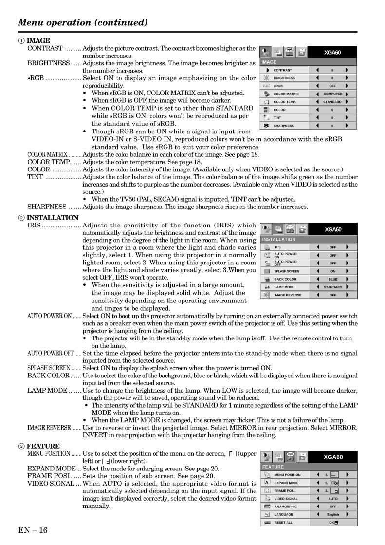
1 IMAGECONTRAST ......... Adjusts the picture contrast. The contrast becomes higher as the
number increases.BRIGHTNESS ..... Adjusts the image brightness. The image becomes brighter as
the number increases.sRGB .................... Select ON to display an image emphasizing on the color
reproducibility.• When sRGB is ON, COLOR MATRIX can’t be adjusted.• When sRGB is OFF, the image will become darker.• When COLOR TEMP is set to other than STANDARD
while sRGB is ON, colors won’t be reproduced as perthe standard value of sRGB.
• Though sRGB can be ON while a signal is input fromVIDEO-IN or S-VIDEO IN, reproduced colors won’t be in accordance with the sRGBstandard value. Use sRGB to suit your color preference.
COLOR MATRIX ......... Adjusts the color balance in each color of the image. See page 18.COLOR TEMP. .... Adjusts the color temperature. See page 18.COLOR ................ Adjusts the color intensity of the image. (Available only when VIDEO is selected as the source.)TINT .................... Adjusts the color balance of the image. The color balance of the image shifts green as the number
increases and shifts to purple as the number decreases. (Available only when VIDEO is selected as thesource.)• When the TV50 (PAL, SECAM) signal is inputted, TINT can’t be adjusted.
SHARPNESS ....... Adjusts the image sharpness. The image sharpness rises as the number increases.
2 INSTALLATIONIRIS ...................... Adjusts the sensitivity of the function (IRIS) which
automatically adjusts the brightness and contrast of the imagedepending on the degree of the light in the room. When usingthis projector in a room where the light and shade variesslightly, select 1. When using this projector in a normallylighted room, select 2. When using this projector in a roomwhere the light and shade varies greatly, select 3.When youselect OFF, IRIS won’t operate.• When the sensitivity is adjusted in a large amount,
the image may be displayed solid white. Adjust thesensitivity depending on the operating environmentand imges to be displayed.
AUTO POWER ON ...... Select ON to boot up the projector automatically by turning on an externally connected power switchsuch as a breaker even when the main power switch of the projector is off. Use this setting when theprojector is hanging from the ceiling.• The projector will be in the stand-by mode when the lamp is off. Use the remote control to turn
on the lamp.AUTO POWER OFF .... Set the time elapsed before the projector enters into the stand-by mode when there is no signal
inputted from the selected source.SPLASH SCREEN ....... Select ON to display the splash screen when the power is turned ON.BACK COLOR...... Use to select the color of the background, blue or black, which will be displayed when there is no signal
inputted from the selected source.LAMP MODE ....... Use to change the brightness of the lamp. When LOW is selected, the image will become darker,
though the power will be saved, operating sound will be reduced. • The intensity of the lamp will be STANDARD for 1 minute regardless of the setting of the LAMP
MODE when the lamp turns on.• When the LAMP MODE is changed, the screen may flicker. This is not a failure of the lamp.
IMAGE REVERSE ...... Use to reverse or invert the projected image. Select MIRROR in rear projection. Select MIRROR,INVERT in rear projection with the projector hanging from the ceiling.
3 FEATUREMENU POSITION ....... Use to select the position of the menu on the screen, (upper
left) or (lower right).EXPAND MODE .. Select the mode for enlarging screen. See page 20.FRAME POSI. .... Sets the position of sub screen. See page 20.VIDEO SIGNAL ... When AUTO is selected, the appropriate video format is
automatically selected depending on the input signal. If theimage isn’t displayed correctly, select the desired video formatmanually.
CONTRAST
IMAGE
0
BRIGHTNESS 0
STANDARD
0
COLOR
0
0
XGA60
COMPUTER
OFF
TINT
COLOR TEMP.
SHARPNESS
COLOR MATRIX
sRGB
opt.
Menu operation (continued)
EN – 17
EN
GL
ISH
ANAMORPHIC .... Select ON when playing DVD discs containing data of letterboxed images.LANGUAGE ........ Use to select the language used in the menus. ( / English / Español / Deutsch / Français / Italiano
/ )RESET ALL ......... Use to reset the MENU settings (except LANGUAGE).
• When the LANGUAGE in FEATURE menu is set to English and NTSC video format is selected, the brightness isdecreased 15 points by set-up cancel function for U.S. (The indicated value is not changed.) The image becomes darker,but this is not a failure of the projector.
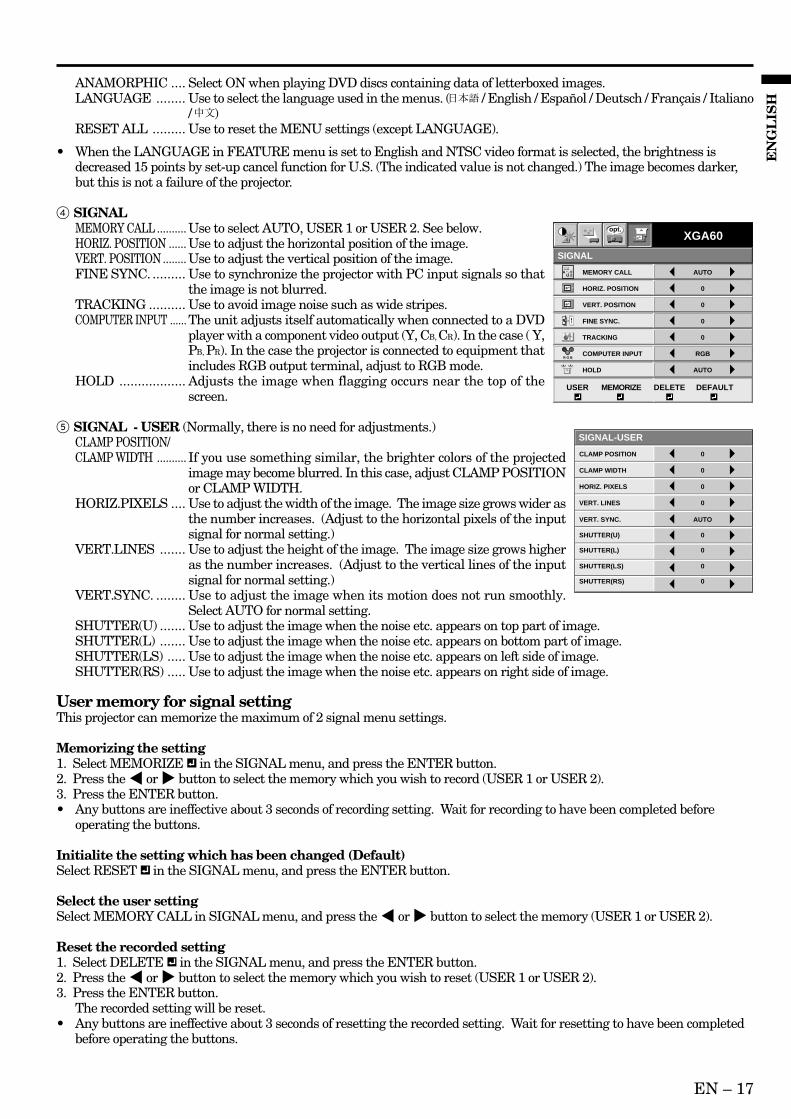
4 SIGNALMEMORY CALL .......... Use to select AUTO, USER 1 or USER 2. See below.HORIZ. POSITION ...... Use to adjust the horizontal position of the image.VERT. POSITION ........ Use to adjust the vertical position of the image.FINE SYNC. ......... Use to synchronize the projector with PC input signals so that
the image is not blurred.TRACKING .......... Use to avoid image noise such as wide stripes.COMPUTER INPUT ...... The unit adjusts itself automatically when connected to a DVD
player with a component video output (Y, CB, CR). In the case ( Y,PB, PR). In the case the projector is connected to equipment thatincludes RGB output terminal, adjust to RGB mode.
HOLD .................. Adjusts the image when flagging occurs near the top of thescreen.
5 SIGNAL - USER (Normally, there is no need for adjustments.)CLAMP POSITION/CLAMP WIDTH .......... If you use something similar, the brighter colors of the projected
image may become blurred. In this case, adjust CLAMP POSITIONor CLAMP WIDTH.
HORIZ.PIXELS .... Use to adjust the width of the image. The image size grows wider asthe number increases. (Adjust to the horizontal pixels of the inputsignal for normal setting.)
VERT.LINES ....... Use to adjust the height of the image. The image size grows higheras the number increases. (Adjust to the vertical lines of the inputsignal for normal setting.)
VERT.SYNC. ........ Use to adjust the image when its motion does not run smoothly.Select AUTO for normal setting.
SHUTTER(U) ....... Use to adjust the image when the noise etc. appears on top part of image.SHUTTER(L) ....... Use to adjust the image when the noise etc. appears on bottom part of image.SHUTTER(LS) ..... Use to adjust the image when the noise etc. appears on left side of image.SHUTTER(RS) ..... Use to adjust the image when the noise etc. appears on right side of image.
User memory for signal settingThis projector can memorize the maximum of 2 signal menu settings.
Memorizing the setting1. Select MEMORIZE in the SIGNAL menu, and press the ENTER button.2. Press the $ or % button to select the memory which you wish to record (USER 1 or USER 2).3. Press the ENTER button.• Any buttons are ineffective about 3 seconds of recording setting. Wait for recording to have been completed before
operating the buttons.
Initialite the setting which has been changed (Default)Select RESET in the SIGNAL menu, and press the ENTER button.
Select the user settingSelect MEMORY CALL in SIGNAL menu, and press the $ or % button to select the memory (USER 1 or USER 2).
Reset the recorded setting1. Select DELETE in the SIGNAL menu, and press the ENTER button.2. Press the $ or % button to select the memory which you wish to reset (USER 1 or USER 2).3. Press the ENTER button.
The recorded setting will be reset.• Any buttons are ineffective about 3 seconds of resetting the recorded setting. Wait for resetting to have been completed
before operating the buttons.
CLAMP POSITION
SIGNAL-USER
0
CLAMP WIDTH 0
HORIZ. PIXELS 0
SHUTTER(RS) 0
VERT. LINES 0
VERT. SYNC. AUTO
SHUTTER(LS) 0
SHUTTER(L) 0
SHUTTER(U) 0
R G BR G B
AU MEMORY CALL
SIGNAL
AUTO
HORIZ. POSITION 0
VERT. POSITION 0
TRACKING 0
COMPUTER INPUT RGB
FINE SYNC. 0
HOLD AUTO
USER MEMORIZE DELETE DEFAULT
XGA60opt.
EN – 18
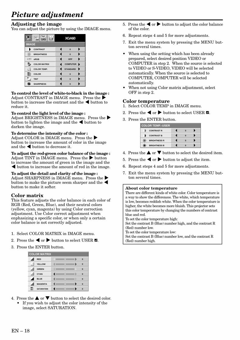
Adjusting the imageYou can adjust the picture by using the IMAGE menu.
To control the level of white-to-black in the image :Adjust CONTRAST in IMAGE menu. Press the %button to increase the contrast and the $ button toreduce it.
To control the light level of the image :Adjust BRIGHTNESS in IMAGE menu. Press the %button to lighten the image and the $ button todarken the image.
To determine the intensity of the color :Adjust COLOR in IMAGE menu. Press the %button to increase the amount of color in the imageand the $ button to decrease it.
To adjust the red-green color balance of the image :Adjust TINT in IMAGE menu. Press the % buttonto increase the amount of green in the image and the$ button to increase the amount of red in the image.
To adjust the detail and clarity of the image :Adjust SHARPNESS in IMAGE menu. Press the %button to make the picture seem sharper and the $button to make it softer.
Color matrixThis feature adjusts the color balance in each color ofRGB (Red, Green, Blue), and their neutral colors(yellow, cyan, magenta) by using Color correctionadjustment. Use Color correct adjustment whenenphasizing a specific color, or when only a certaincolor balance is not correctly adjusted.
1. Select COLOR MATRIX in IMAGE menu.
2. Press the $ or % button to select USER .
3. Press the ENTER button.
4. Press the or button to select the desired color.• If you wish to adjust the color intensity of the
image, select SATURATION.
Picture adjustment
CONTRAST R
COLOR TEMP.-USER
0
CONTRAST B 0
BRIGHTNESS R 0
BRIGHTNESS B 0
CONTRAST
IMAGE
0
BRIGHTNESS 0
STANDARD
0
COLOR
0
0
XGA60
COMPUTER
OFF
TINT
COLOR TEMP.
SHARPNESS
COLOR MATRIX
sRGB
opt.
About color temperatureThere are different kinds of white color. Color temperature isa way to show the differences. The white, which temperatureis low, becomes reddish white. When the color temperature ishigher, the white becomes more bluish. This projector setsthis color temperature by changing the numbers of contrastblue and red.To set the color temperature high:Set the contrast B (Blue) number high, and the contrast R(Red) number low.To set the color temperature low:Set the contrast B (Blue) number low, and the contrast R(Red) number high.
5. Press the $ or % button to adjust the color balanceof the color.
6. Repeat steps 4 and 5 for more adjustments.
7. Exit the menu system by pressing the MENU but-ton several times.
• When using the setting which has been alreadyprepared, select desired position VIDEO orCOMPUTER in step 2. When the source is selectedto VIDEO or S-VIDEO, VIDEO will be selectedautomatically. When the source is selected toCOMPUTER, COMPUTER will be selectedautomatically.
• When not using Color matrix adjustment, selectOFF in step 2.
Color temperature1. Select COLOR TEMP in IMAGE menu.
2. Press the $ or % button to select USER .
3. Press the ENTER button.
4. Press the or button to select the desired item.
5. Press the $ or % button to adjust the item.
6. Repeat steps 4 and 5 for more adjustments.
7. Exit the menu system by pressing the MENU but-ton several times.
COLOR MATRIX
RED 0
0
0
0
0
GREEN
BLUE
YELLOW
CYAN
MAGENTA 0
SATURATION 0
EN – 19
EN
GL
ISH
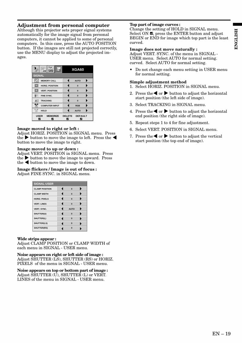
Adjustment from personal computerAlthough this projector sets proper signal systemsautomatically for the image signal from personalcomputers, it cannot be applied to some of personalcomputers. In this case, press the AUTO POSITIONbutton. If the images are still not projected correctly,use the MENU display to adjust the projected im-ages.
Image moved to right or left :Adjust HORIZ. POSITION in SIGNAL menu. Pressthe % button to move the image to left. Press the $button to move the image to right.
Image moved to up or down :Adjust VERT. POSITION in SIGNAL menu. Pressthe % button to move the image to upward. Pressthe $ button to move the image to down.
Image flickers / Image is out of focus :Adjust FINE SYNC. in SIGNAL menu.
Wide strips appear :Adjust CLAMP POSITION or CLAMP WIDTH ofeach menu in SIGNAL - USER menu.
Noise appears on right or left side of image :Adjust SHUTTER (LS), SHUTTER (RS) or HORIZ.PIXELS of the menu in SIGNAL - USER menu.
Noise appears on top or bottom part of image :Adjust SHUTTER (U), SHUTTER (L) or VERT.LINES of the menu in SIGNAL - USER menu.
R G BR G B
AU MEMORY CALL
SIGNAL
AUTO
HORIZ. POSITION 0
VERT. POSITION 0
TRACKING 0
COMPUTER INPUT RGB
FINE SYNC. 0
HOLD AUTO
USER MEMORIZE DELETE DEFAULT
XGA60opt.
CLAMP POSITION
SIGNAL-USER
0
CLAMP WIDTH 0
HORIZ. PIXELS 0
SHUTTER(RS) 0
VERT. LINES 0
VERT. SYNC. AUTO
SHUTTER(LS) 0
SHUTTER(L) 0
SHUTTER(U) 0
Top part of image curves :Change the setting of HOLD in SIGNAL menu.Select ON , press the ENTER button and adjustBEGIN or END for image which top part is the leastcurved.
Image does not move naturally :Adjust VERT. SYNC. of the menu in SIGNAL -USER menu. Select AUTO for normal setting.curved. Select AUTO for normal setting.
• Do not change each menu setting in USER menufor normal setting.
Simple adjustment method1. Select HORIZ. POSITION in SIGNAL menu.
2. Press the$ or % button to adjust the horizontalstart position (the left side of image).
3. Select TRACKING in SIGNAL menu.
4. Press the$ or % button to adjust the horizontalend position (the right side of image).
5. Repeat steps 1 to 4 for fine adjustment.
6. Select VERT. POSITION in SIGNAL menu.
7. Press the$ or % button to adjust the verticalstart position (the top end of image).
EN – 20
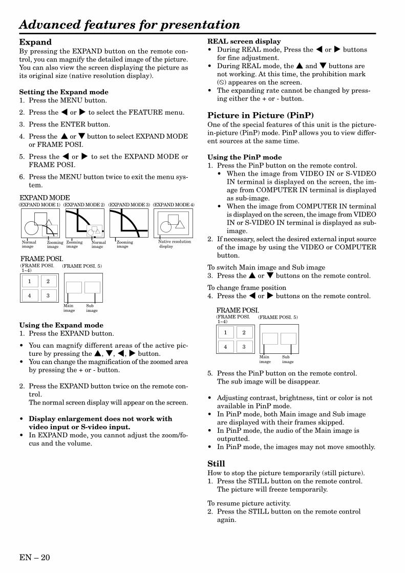
Advanced features for presentationExpandBy pressing the EXPAND button on the remote con-trol, you can magnify the detailed image of the picture.You can also view the screen displaying the picture asits original size (native resolution display).
Setting the Expand mode1. Press the MENU button.
2. Press the $ or % to select the FEATURE menu.
3. Press the ENTER button.
4. Press the or button to select EXPAND MODEor FRAME POSI.
5. Press the $ or % to set the EXPAND MODE orFRAME POSI.
6. Press the MENU button twice to exit the menu sys-tem.
REAL screen display• During REAL mode, Press the $ or % buttons
for fine adjustment.• During REAL mode, the and buttons are
not working. At this time, the prohibition mark( ) appeares on the screen.
• The expanding rate cannot be changed by press-ing either the + or - button.
Picture in Picture (PinP)One of the special features of this unit is the picture-in-picture (PinP) mode. PinP allows you to view differ-ent sources at the same time.
Using the PinP mode1. Press the PinP button on the remote control.
• When the image from VIDEO IN or S-VIDEOIN terminal is displayed on the screen, the im-age from COMPUTER IN terminal is displayedas sub-image.
• When the image from COMPUTER IN terminalis displayed on the screen, the image from VIDEOIN or S-VIDEO IN terminal is displayed as sub-image.
2. If necessary, select the desired external input sourceof the image by using the VIDEO or COMPUTERbutton.
To switch Main image and Sub image3. Press the or buttons on the remote control.
To change frame position4. Press the $ or % buttons on the remote control.
5. Press the PinP button on the remote control.The sub image will be disappear.
• Adjusting contrast, brightness, tint or color is notavailable in PinP mode.
• In PinP mode, both Main image and Sub imageare displayed with their frames skipped.
• In PinP mode, the audio of the Main image isoutputted.
• In PinP mode, the images may not move smoothly.
StillHow to stop the picture temporarily (still picture).1. Press the STILL button on the remote control.
The picture will freeze temporarily.
To resume picture activity.2. Press the STILL button on the remote control
again.
Normalimage
Native resolution display
Zoomingimage
(EXPAND MODE 1)
Zoomingimage
Normalimage
(EXPAND MODE 2)
Zoomingimage
(EXPAND MODE 3) (EXPAND MODE 4)EXPAND MODE
(FRAME POSI. 1~4)
(FRAME POSI. 5)
1 2
34
Mainimage
Subimage
FRAME POSI.
Using the Expand mode1. Press the EXPAND button.
• You can magnify different areas of the active pic-ture by pressing the , , $, % button.
• You can change the magnification of the zoomed areaby pressing the + or - button.
2. Press the EXPAND button twice on the remote con-trol.The normal screen display will appear on the screen.
• Display enlargement does not work withvideo input or S-video input.
• In EXPAND mode, you cannot adjust the zoom/fo-cus and the volume.
(FRAME POSI. 1~4)
(FRAME POSI. 5)
1 2
34
Mainimage
Subimage
FRAME POSI.

EN – 21
EN
GL
ISH
Mouse remote controlBy connecting to personal computer through the USB or PS/2 port, you can operate your computer with theprojector remote control.
Projector + computer with USB connector
Operation
• Turn off computer and the projector before connecting with PS/2 port. When connecting the computer with theprojector when the personal computer is on, the remote control does not work as a mouse. In that case, restartthe personal computer.
• When the projector is connected with USB terminal and RS-232C terminal at the same time, only the termi-nal which the projector recognizes first will work.
• When you use the RS-232C cable together with an extension cable, the function may not work correctly.
• You can use the mouse remote control function with a computer supporting USB only. If your system isWindows® 98 or higher, your computer supports USB in standard. If your system is Windows® 95 or lower,please contact your dealer. If your computer is Macintosh® with USB port, you can use this function.
• When the lamp is turned ON, the computer connected with the USB cable may not work correctly. In thiscase, restart the projector and the computer. If possible, you should disconnect the USB cable when the lampis turned ON.
Projector + computer with PS/2 connector
ENTER
RIGHT CLICK
LASER
COMPUTER VIDEO ZOOM/FOCUS
KEYSTONE
VOLMEAUTO
POSITION
MENU
right clickThis operates in the same way as the right button on the computer mouse.
mouse pointerUse to move the cursor on the image, instead of the computer mouse.
left clickThis operates in the same way as the left button on the computer mouse.
REMOTE
AUDIO 2 INCOMPUTER 2 IN
AUDIO OUTCOMPUTER OUT
AUDIO 1 INCOMPUTER 1 IN
DIGITALANALOG
INPUT SELECT
MAIN
AC IN
O I
L
R
S-VIDEOVIDEO
AUDIO
VIDEO 1 IN VIDEO 2 IN
USBRS-232C
to USB
USB cable
to USB port
USB 4P (type B)
USB 4P (type A)
REMOTE
AUDIO 2 INCOMPUTER 2 IN
AUDIO OUTCOMPUTER OUT
AUDIO 1 INCOMPUTER 1 IN
DIGITALANALOG
INPUT SELECT
MAIN
AC IN
O I
L
R
S-VIDEOVIDEO
AUDIO
VIDEO 1 IN VIDEO 2 IN
USBRS-232C
to RS-232Cterminal
PS/2 adaptor
to mouse (PS/2) port
D-SUB 9PMini DIN 8P D-SUB 9P Mini DIN 6P
RS-232C cable
EN – 22
What you can do with HUBThis projector is equipped with a relaying HUB.You can do: – Easy Data (File) Exchange – Projection of the data in the compters connected
via the HUB – Connection with an existing LAN – Print out through a Network printer
Example of Network System1) Connect laptop computers directly to the internal
HUB. Copy data to the computer which is con-nected to this projector with RGB connection, andproject the data.
• You can also send presentation data to othercomputers easily.
2) Connect an existing LAN network to the internalHUB. Print out data through a Network printerwhich is connected to the existing LAN.
• Read out data using the computer which has theIP address of the existing LAN network and thenprint them out.
• A printer driver, etc. may be necessary for printing.Please refer to the owner’s guide of the printer.
Required Hardware1. HUB TERMINAL (built-in)
2. LAN CABLE (at least 2 cables, included in thebox.)
3. LAN CARD (Network Card)Some computers have a built-in LAN port. If yourcomputer does’t have one, you need at least twoLAN cards.• They are not included in the box.
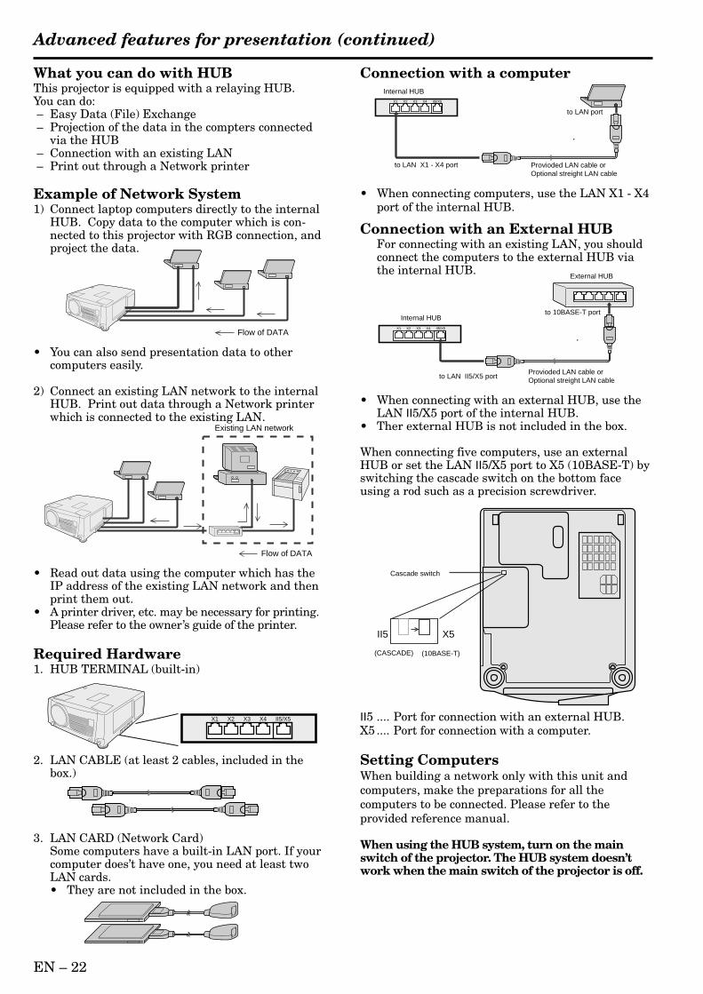
Connection with a computer
• When connecting computers, use the LAN X1 - X4port of the internal HUB.
Connection with an External HUBFor connecting with an existing LAN, you shouldconnect the computers to the external HUB viathe internal HUB.
• When connecting with an external HUB, use theLAN II5/X5 port of the internal HUB.
• Ther external HUB is not included in the box.
When connecting five computers, use an externalHUB or set the LAN II5/X5 port to X5 (10BASE-T) byswitching the cascade switch on the bottom faceusing a rod such as a precision screwdriver.
II5 .... Port for connection with an external HUB.X5 .... Port for connection with a computer.
Setting ComputersWhen building a network only with this unit andcomputers, make the preparations for all thecomputers to be connected. Please refer to theprovided reference manual.
When using the HUB system, turn on the mainswitch of the projector. The HUB system doesn’twork when the main switch of the projector is off.
X1 X2 X3 X4 II5/X5
Flow of DATA
Existing LAN network
Flow of DATA
X1 X2 X3 X4 II5/X5
Internal HUB
External HUB
to LAN II5/X5 port
to 10BASE-T port
Provioded LAN cable orOptional streight LAN cable
to LAN port
X1 X2 X3 X4 II5/X5
Internal HUB
to LAN X1 - X4 port Provioded LAN cable orOptional streight LAN cable
Cascade switch
(CASCADE)
II5 X5
(10BASE-T)
Advanced features for presentation (continued)
EN – 23
EN
GL
ISH
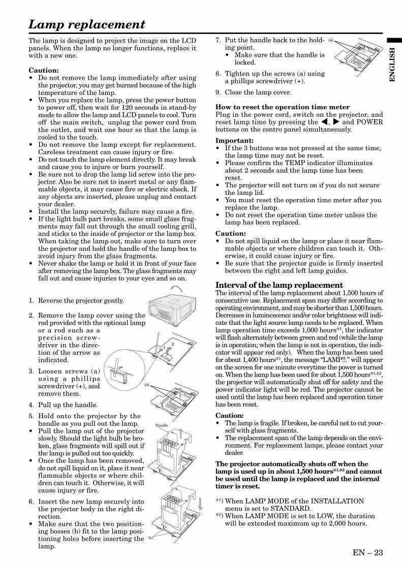
The lamp is designed to project the image on the LCDpanels. When the lamp no longer functions, replace itwith a new one.
Caution:• Do not remove the lamp immediately after using
the projector, you may get burned because of the hightemperature of the lamp.
• When you replace the lamp, press the power buttonto power off, then wait for 120 seconds in stand-bymode to allow the lamp and LCD panels to cool. Turnoff the main switch, unplug the power cord fromthe outlet, and wait one hour so that the lamp iscooled to the touch.
• Do not remove the lamp except for replacement.Careless treatment can cause injury or fire.
• Do not touch the lamp element directly. It may breakand cause you to injure or burn yourself.
• Be sure not to drop the lamp lid screw into the pro-jector. Also be sure not to insert metal or any flam-mable objects, it may cause fire or electric shock. Ifany objects are inserted, please unplug and contactyour dealer.
• Install the lamp securely, failure may cause a fire.• If the light bulb part breaks, some small glass frag-
ments may fall out through the small cooling grill,and sticks to the inside of projector or the lamp box.When taking the lamp out, make sure to turn overthe projector and hold the handle of the lamp box toavoid injury from the glass fragments.
• Never shake the lamp or hold it in front of your faceafter removing the lamp box. The glass fragments mayfall out and cause injuries to your eyes and so on.
1. Reverse the projector gently.
2. Remove the lamp cover using therod provided with the optional lampor a rod such as aprecision screw-driver in the direc-tion of the arrow asindicated.
3. Loosen screws (a)using a phil l ipsscrewdriver (+), andremove them.
4. Pull up the handle.
5. Hold onto the projector by thehandle as you pull out the lamp.
• Pull the lamp out of the projectorslowly. Should the light bulb be bro-ken, glass fragments will spill out ifthe lamp is pulled out too quickly.
• Once the lamp has been removed,do not spill liquid on it, place it nearflammable objects or where chil-dren can touch it. Otherwise, it willcause injury or fire.
6. Insert the new lamp securely intothe projector body in the right di-rection.
• Make sure that the two position-ing bosses (b) fit to the lamp posi-tioning holes before inserting thelamp.
7. Put the handle back to the hold-ing point.• Make sure that the handle is
locked.
8. Tighten up the screws (a) usinga phillips screwdriver (+).
9. Close the lamp cover.
How to reset the operation time meterPlug in the power cord, switch on the projector, andreset lamp time by pressing the $, % and POWERbuttons on the contro panel simultaneously.
Important:• If the 3 buttons was not pressed at the same time,
the lamp time may not be reset.• Please confirm the TEMP indicator illuminates
about 2 seconds and the lamp time has beenreset.
• The projector will not turn on if you do not securethe lamp lid.
• You must reset the operation time meter after youreplace the lamp.
• Do not reset the operation time meter unless thelamp has been replaced.
Caution:• Do not spill liquid on the lamp or place it near flam-
mable objects or where children can touch it. Oth-erwise, it could cause injury or fire.
• Be sure that the projector guide is firmly insertedbetween the right and left lamp guides.
Interval of the lamp replacementThe interval of the lamp replacement about 1,500 hours ofconsecutive use. Replacement span may differ according tooperating environment, and may be shorter than 1,500 hours.Decreases in luminescence and/or color brightness will indi-cate that the light source lamp needs to be replaced. Whenlamp operation time exceeds 1,000 hours*1, the indicatorwill flash alternately between green and red (while the lampis in operation; when the lamp is not in operation, the indi-cator will appear red only). When the lamp has been usedfor about 1,400 hours*1, the message “LAMP!!.” will appearon the screen for one minute everytime the power is turnedon. When the lamp has been used for about 1,500 hours*1,*2,the projector will automatically shut off for safety and thepower indicator light will be red. The projector cannot beused until the lamp has been replaced and operation timerhas been reset.
Caution:• The lamp is fragile. If broken, be careful not to cut your-
self with glass fragments.• The replacement span of the lamp depends on the envi-
ronment. For replacement lamps, please contact yourdealer.
The projector automatically shuts off when thelamp is used up in about 1,500 hours*1,*2 and cannotbe used until the lamp is replaced and the internaltimer is reset.
*1) When LAMP MODE of the INSTALLATIONmenu is set to STANDARD.
*2) When LAMP MODE is set to LOW, the durationwill be extended maximum up to 2,000 hours.
12
(a)
Lamp replacement
Handle
(b)
(a)
EN – 24
MaintenanceCaution:Be sure to turn off the projector and unplug the powercord from the wall outlet before you perform any main-tenance on the projector.
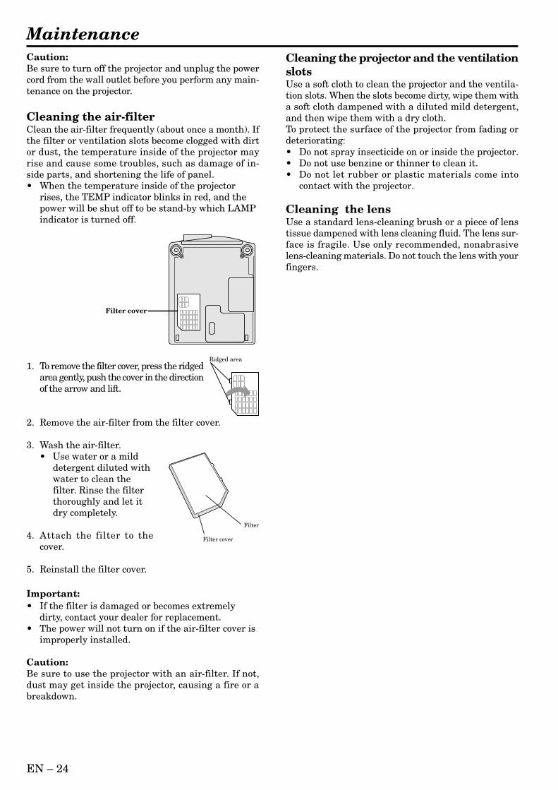
Cleaning the air-filterClean the air-filter frequently (about once a month). Ifthe filter or ventilation slots become clogged with dirtor dust, the temperature inside of the projector mayrise and cause some troubles, such as damage of in-side parts, and shortening the life of panel.• When the temperature inside of the projector
rises, the TEMP indicator blinks in red, and thepower will be shut off to be stand-by which LAMPindicator is turned off.
1. To remove the filter cover, press the ridgedarea gently, push the cover in the directionof the arrow and lift.
2. Remove the air-filter from the filter cover.
3. Wash the air-filter.• Use water or a mild
detergent diluted withwater to clean thefilter. Rinse the filterthoroughly and let itdry completely.
4. Attach the filter to thecover.
5. Reinstall the filter cover.
Important:• If the filter is damaged or becomes extremely
dirty, contact your dealer for replacement.• The power will not turn on if the air-filter cover is
improperly installed.
Caution:Be sure to use the projector with an air-filter. If not,dust may get inside the projector, causing a fire or abreakdown.
Cleaning the projector and the ventilationslotsUse a soft cloth to clean the projector and the ventila-tion slots. When the slots become dirty, wipe them witha soft cloth dampened with a diluted mild detergent,and then wipe them with a dry cloth.To protect the surface of the projector from fading ordeteriorating:• Do not spray insecticide on or inside the projector.• Do not use benzine or thinner to clean it.• Do not let rubber or plastic materials come into
contact with the projector.
Cleaning the lensUse a standard lens-cleaning brush or a piece of lenstissue dampened with lens cleaning fluid. The lens sur-face is fragile. Use only recommended, nonabrasivelens-cleaning materials. Do not touch the lens with yourfingers.
Ridged area
Filter
Filter cover
Filter cover
EN – 25
EN
GL
ISH
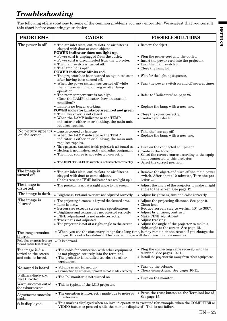
TroubleshootingThe following offers solutions to some of the common problems you may encounter. We suggest that you consultthis chart before contacting your dealer.
CAUSE• The air inlet slots, outlet slots or air filter is
clogged with dust or some objects.POWER indicator does not light up.• Power cord is unplugged from the outlet.• Power cord is disconnected from the projector.• The main switch is turned off.• The lamp lid is open.POWER indicator blinks red.• The projector has been turned on again too soon
after having been turned off.• When the power switch was turned off while
the fan was running, during or after lampoperation.
• The room temperature is too high.(Does the LAMP indicator show an unusualcondition?)
• Lamp is no longer working.POWER indicator blinks between red and green.• The filter cover is not closed.• When the LAMP indicator or the TEMP
indicator is either on or blinking, the main unitrequires repairs.
• Lens is covered by lens cap.• When the LAMP indicator or the TEMP
indicator is either on or blinking, the main unitrequires repairs.
• The equipment connected to this projector is not turned on.• Hookup is not made correctly with other equipment.• The input source is not selected correctly.
• The INPUT SELECT switch is not selected correctly.
• The air inlet slots, outlet slots or air filter isclogged with dust or some objects.(In this case, the TEMP indicator does not light up.)
• The projector is not at a right angle to the screen.
• Brightness, tint and color are not adjusted correctly.
• The projecting distance is beyond the focused area.• Lens is dirty.• Screen size exceeds screen size specifications.• Brightness and contrast are not adjusted correctly.• FINE adjustment is not made correctly.• Tracking is not adjusted.• The projector is not at a right angle to the screen.
• Remove the object.
• Plug the power cord into the outlet.• Insert the power cord into the projector.• Turn the main switch on.• Close the lamp lid.
• Wait for the lighting sequence.
• Turn the power switch on and off several times.
• Refer to "Indicators" on page 26.
• Replace the lamp with a new one.
• Close the cover correctly.• Contact your dealer.
• Take the lens cap off.• Replace the lamp with a new one.
• Turn on the connected equipment.• Confirm the hookup.• Select the correct source according to the equip-
ment connected to this projector.• Select the correct position.
• Remove the object and turn off the main powerswitch. After about 10 minutes, Turn the pro-jector on.
• Adjust the angle of the projector to make a rightangle to the screen. See page 12.
• Adjust brightness, tint and color correctly.
• Adjust the projecting distance. See page 9.• Clean lens.• Reduce screen size to within 40" to 300".• Adjust brightness, contrast.• Make FINE adjustment.• Adjust tracking.• Adjust the angle of the projector to make a
right angle to the screen. See page 12.• When you see the stationary image for a long time, it may remain on the screen if you change the
image. It is not a breakdown. The blurred image will disappear in a few minutes.
• It is normal.
• The cable for connection with other equipmentis not plugged securely into the terminal.
• The projector is installed too close to otherequipment.
• Volume is not turned up.• Connection to other equipment is not made correctly.
• The PC monitor is not turned on.
• This is typical of the LCD projector.
• The operation is incorrectly made due to noise orinterference.
• Plug the connecting cable securely into theterminal. See pages 10-11.
• Install the projector far away from other equipment.
• Turn up the volume.• Check connections. See pages 10-11.
• Turn on the monitor.
• Press the reset button on the Terminal board.See page 15.
POSSIBLE SOLUTIONSPROBLEMSThe power is off.
No picture appearson the screen.
The image isturned off.
The image isdistorted.The image is dark.
The image isblurred.
Red, blue or green dots areviewed on the text of image.
The image remainsblurred.
The image is dis-torted on the screenand noise is heard.
No sound is heard.
Adjustments cannot bemade.
Warm air comes out ofthe exhaust vents.
Nothing is displayed onthe PC monitor.
is displayed. • This mark is displayed when an invalid operation is executed (for example, when the COMPUTER orVIDEO button is pressed while the menu is displayed). This is not failure.
EN – 26
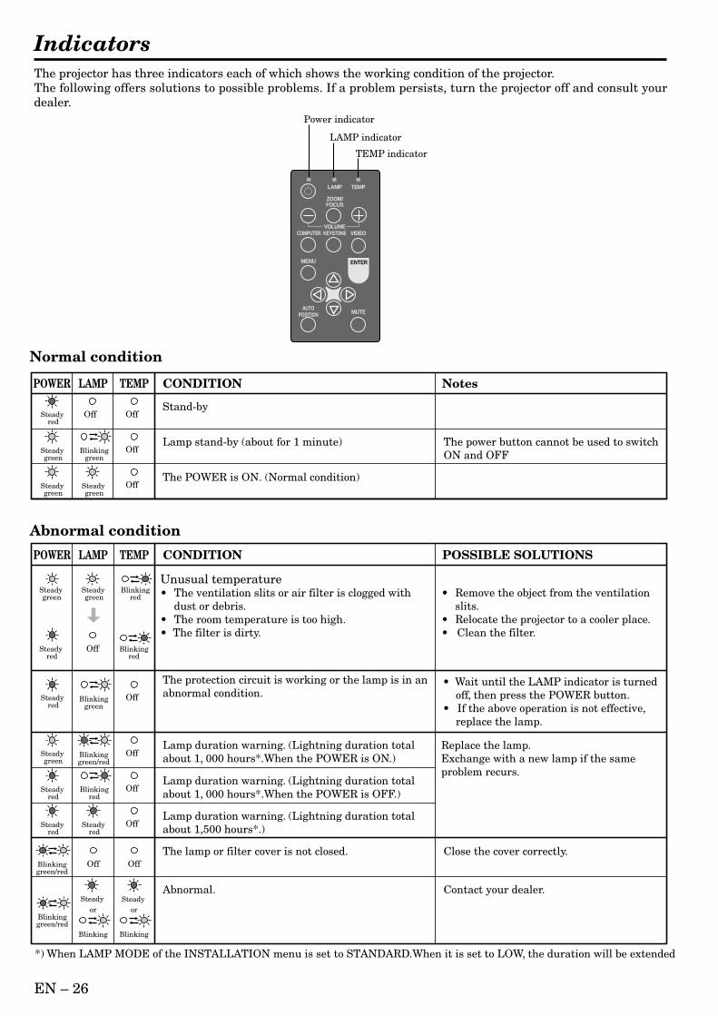
IndicatorsThe projector has three indicators each of which shows the working condition of the projector.The following offers solutions to possible problems. If a problem persists, turn the projector off and consult yourdealer.
Power indicator
LAMP indicator
TEMP indicator
LAMP
VOLUME
ZOOM/FOCUS
KEYSTONE
TEMP
VIDEOCOMPUTER
MUTEAUTO
POSITION
MENU ENTER
Normal condition
Abnormal condition
Steady red
Steady green
Steady green
Blinkinggreen
Steady green
POWER LAMP TEMP CONDITION Notes
The POWER is ON. (Normal condition)
Lamp stand-by (about for 1 minute) The power button cannot be used to switchON and OFF
Stand-byOffOff
Off
Off
Steady green
Blinkinggreen/red
Blinkinggreen/red
Blinkinggreen/red
Steady red
Steady green
Steady green
Blinkingred
Blinkingred
POWER LAMP TEMP CONDITION POSSIBLE SOLUTIONS
Lamp duration warning. (Lightning duration total about 1, 000 hours*.When the POWER is ON.)
Steady red
Blinkingred
Lamp duration warning. (Lightning duration total about 1, 000 hours*.When the POWER is OFF.)
Steady red
Lamp duration warning. (Lightning duration total about 1,500 hours*.)
The lamp or filter cover is not closed.
The protection circuit is working or the lamp is in anabnormal condition.
Close the cover correctly.
or or
Blinking Blinking
Abnormal. Contact your dealer.
Off
Off
Steady red
Blinkinggreen
Off
Off
Off
OffOff
Steady red
Steady Steady
Unusual temperature• The ventilation slits or air filter is clogged with
dust or debris.• The room temperature is too high.• The filter is dirty.
• Remove the object from the ventilationslits.
• Relocate the projector to a cooler place.• Clean the filter.
Replace the lamp.Exchange with a new lamp if the same problem recurs.
• Wait until the LAMP indicator is turned off, then press the POWER button.
• If the above operation is not effective, replace the lamp.
*) When LAMP MODE of the INSTALLATION menu is set to STANDARD.When it is set to LOW, the duration will be extended.
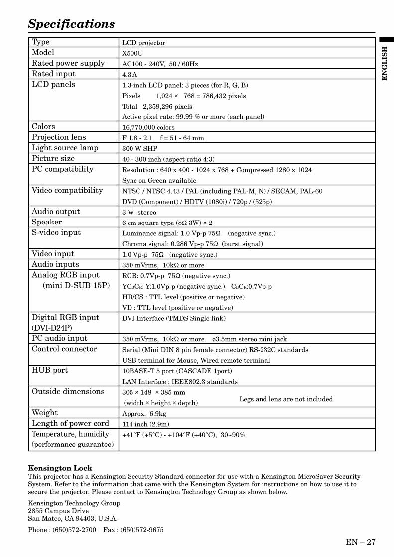
EN – 27
EN
GL
ISH
SpecificationsLCD projector
X500U
AC100 - 240V, 50 / 60Hz
4.3 A
1.3-inch LCD panel: 3 pieces (for R, G, B)
Pixels 1,024 × 768 = 786,432 pixels
Total 2,359,296 pixels
Active pixel rate: 99.99 % or more (each panel)
16,770,000 colors
F 1.8 - 2.1 f = 51 - 64 mm
300 W SHP
40 - 300 inch (aspect ratio 4:3)
Resolution : 640 x 400 - 1024 x 768 + Compressed 1280 x 1024
Sync on Green available
NTSC / NTSC 4.43 / PAL (including PAL-M, N) / SECAM, PAL-60
DVD (Component) / HDTV (1080i) / 720p / (525p)
3 W stereo
6 cm square type (8Ω 3W) × 2
Luminance signal: 1.0 Vp-p 75Ω (negative sync.)
Chroma signal: 0.286 Vp-p 75Ω (burst signal)
1.0 Vp-p 75Ω (negative sync.)
350 mVrms, 10kΩ or more
RGB: 0.7Vp-p 75Ω (negative sync.)
YCBCR: Y:1.0Vp-p (negative sync.) CBCR:0.7Vp-p
HD/CS : TTL level (positive or negative)
VD : TTL level (positive or negative)
DVI Interface (TMDS Single link)
350 mVrms, 10kΩ or more ø3.5mm stereo mini jack
Serial (Mini DIN 8 pin female connector) RS-232C standards
USB terminal for Mouse, Wired remote terminal
10BASE-T 5 port (CASCADE 1port)
LAN Interface : IEEE802.3 standards
305 × 148 × 385 mm
(width × height × depth)
Approx. 6.9kg
114 inch (2.9m)
+41°F (+5°C) - +104°F (+40°C), 30~90%
TypeModelRated power supplyRated inputLCD panels
ColorsProjection lensLight source lampPicture sizePC compatibility
Video compatibility
Audio outputSpeakerS-video input
Video inputAudio inputsAnalog RGB input (mini D-SUB 15P)
Digital RGB input(DVI-D24P)PC audio inputControl connector
HUB port
Outside dimensions
WeightLength of power cordTemperature, humidity(performance guarantee)
Kensington LockThis projector has a Kensington Security Standard connector for use with a Kensington MicroSaver SecuritySystem. Refer to the information that came with the Kensington System for instructions on how to use it tosecure the projector. Please contact to Kensington Technology Group as shown below.
Kensington Technology Group2855 Campus DriveSan Mateo, CA 94403, U.S.A.
Phone : (650)572-2700 Fax : (650)572-9675
Legs and lens are not included.
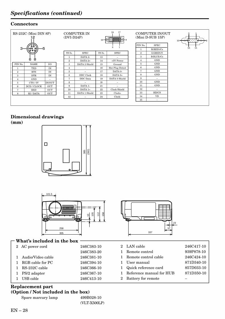
EN – 28
Specifications (continued)
2 LAN cable 246C417-101 Remote control 939P878-101 Remote control cable 246C424-101 User manual 871D340-101 Quick reference card 857D033-101 Reference manual for HUB 871D350-102 Battery for remote –
Connectors
Dimensional drawings(mm)
305
258
23
57
337
101.5
10 158
112
105
(392
)
385
Replacement part(Option / Not included in the box)
Spare marcury lamp 499B028-10(VLT-X500LP)
What’s included in the box2 AC power cord 246C383-10
246C383-201 Audio/Video cable 246C381-101 RGB cable for PC 246C394-101 RS-232C cable 246C366-101 PS/2 adapter 246C367-101 USB cable 246C413-10
PIN No. SPEC
1 R(RED)/CR
2 G(GREEN)/Y
3 B(BLUE)/CB
4 GND
5 GND
6 GND
7 GND
8 GND
9 –
10 GND
11 GND
12 –
13 HD/CS
14 VD
15 –
COMPUTER IN/OUT(Mini D-SUB 15P)
PIN No. NAME I/O
1 TXD IN
2 RTS IN
3 DTR IN
4 GND –
5 CTS / 5V IN/OUT
6 DCD / CLOCK OUT
7 RXD OUT
8 RI / DATA OUT
RS-232C (Mini DIN 8P) COMPUTER IN(DVI-D24P)
PIN No. SPEC PIN No. SPEC
1 DATA 2- 13 –
2 DATA 2+ 14 +5V Power
3 DATA 2 Shield 15 Ground
4 – 16 Hot Plug Detect
5 – 17 DATA 0-
6 DDC Clock 18 DATA 0+
7 DDC Data 19 DATA 0 Shield
8 – 20 –
9 DATA 1- 21 –
10 DATA 1+ 22 Clock Shield
11 DATA 1 Shield 23 Clock+
12 – 24 Clock-
8 1
1724
916
15
11
610
15
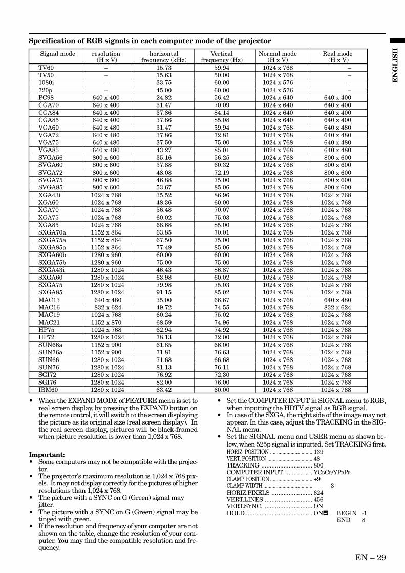
EN – 29
EN
GL
ISH
Specification of RGB signals in each computer mode of the projector
• When the EXPAND MODE of FEATURE menu is set toreal screen display, by pressing the EXPAND button onthe remote control, it will switch to the screen displayingthe picture as its original size (real screen display). Inthe real screen display, pictures will be black-framedwhen picture resolution is lower than 1,024 x 768.
Important:• Some computers may not be compatible with the projec-
tor.• The projector's maximum resolution is 1,024 x 768 pix-
els. It may not display correctly for the pictures of higherresolutions than 1,024 x 768.
• The picture with a SYNC on G (Green) signal mayjitter.
• The picture with a SYNC on G (Green) signal may betinged with green.
• If the resolution and frequency of your computer are notshown on the table, change the resolution of your com-puter. You may find the compatible resolution and fre-quency.
• Set the COMPUTER INPUT in SIGNAL menu to RGB,when inputting the HDTV signal as RGB signal.
• In case of the SXGA, the right side of the image may notappear. In this case, adjust the TRACKING in the SIG-NAL menu.
• Set the SIGNAL menu and USER menu as shown be-low, when 525p signal is inputted. Set TRACKING first.HORIZ. POSITION ............................... 139VERT. POSITION ................................. 48TRACKING .............................. 800COMPUTER INPUT ................ YCBCR/YPBPR
CLAMP POSITION ............................... +9CLAMP WIDTH .................................... 3HORIZ.PIXELS ........................ 624VERT.LINES ............................ 456VERT.SYNC. ............................ ONHOLD ....................................... ON BEGIN -1
END 8
Signal mode resolution horizontal Vertical Normal mode Real mode (H x V) frequency (kHz) frequency (Hz) (H x V) (H x V)
TV60 – 15.73 59.94 1024 x 768 –TV50 – 15.63 50.00 1024 x 768 –1080i – 33.75 60.00 1024 x 576 –720p – 45.00 60.00 1024 x 576 –PC98 640 x 400 24.82 56.42 1024 x 640 640 x 400CGA70 640 x 400 31.47 70.09 1024 x 640 640 x 400CGA84 640 x 400 37.86 84.14 1024 x 640 640 x 400CGA85 640 x 400 37.86 85.08 1024 x 640 640 x 400VGA60 640 x 480 31.47 59.94 1024 x 768 640 x 480VGA72 640 x 480 37.86 72.81 1024 x 768 640 x 480VGA75 640 x 480 37.50 75.00 1024 x 768 640 x 480VGA85 640 x 480 43.27 85.01 1024 x 768 640 x 480SVGA56 800 x 600 35.16 56.25 1024 x 768 800 x 600SVGA60 800 x 600 37.88 60.32 1024 x 768 800 x 600SVGA72 800 x 600 48.08 72.19 1024 x 768 800 x 600SVGA75 800 x 600 46.88 75.00 1024 x 768 800 x 600SVGA85 800 x 600 53.67 85.06 1024 x 768 800 x 600XGA43i 1024 x 768 35.52 86.96 1024 x 768 1024 x 768XGA60 1024 x 768 48.36 60.00 1024 x 768 1024 x 768XGA70 1024 x 768 56.48 70.07 1024 x 768 1024 x 768XGA75 1024 x 768 60.02 75.03 1024 x 768 1024 x 768XGA85 1024 x 768 68.68 85.00 1024 x 768 1024 x 768SXGA70a 1152 x 864 63.85 70.01 1024 x 768 1024 x 768SXGA75a 1152 x 864 67.50 75.00 1024 x 768 1024 x 768SXGA85a 1152 x 864 77.49 85.06 1024 x 768 1024 x 768SXGA60b 1280 x 960 60.00 60.00 1024 x 768 1024 x 768SXGA75b 1280 x 960 75.00 75.00 1024 x 768 1024 x 768SXGA43i 1280 x 1024 46.43 86.87 1024 x 768 1024 x 768SXGA60 1280 x 1024 63.98 60.02 1024 x 768 1024 x 768SXGA75 1280 x 1024 79.98 75.03 1024 x 768 1024 x 768SXGA85 1280 x 1024 91.15 85.02 1024 x 768 1024 x 768MAC13 640 x 480 35.00 66.67 1024 x 768 640 x 480MAC16 832 x 624 49.72 74.55 1024 x 768 832 x 624MAC19 1024 x 768 60.24 75.02 1024 x 768 1024 x 768MAC21 1152 x 870 68.59 74.96 1024 x 768 1024 x 768HP75 1024 x 768 62.94 74.92 1024 x 768 1024 x 768HP72 1280 x 1024 78.13 72.00 1024 x 768 1024 x 768SUN66a 1152 x 900 61.85 66.00 1024 x 768 1024 x 768SUN76a 1152 x 900 71.81 76.63 1024 x 768 1024 x 768SUN66 1280 x 1024 71.68 66.68 1024 x 768 1024 x 768SUN76 1280 x 1024 81.13 76.11 1024 x 768 1024 x 768SGI72 1280 x 1024 76.92 72.30 1024 x 768 1024 x 768SGI76 1280 x 1024 82.00 76.00 1024 x 768 1024 x 768IBM60 1280 x 1024 63.42 60.00 1024 x 768 1024 x 768

Printed in Japan871D340B10
Manufactured by Mitsubishi Electric Corporation1 Zusho Baba, Nagaokakyo-City, Kyoto Japan
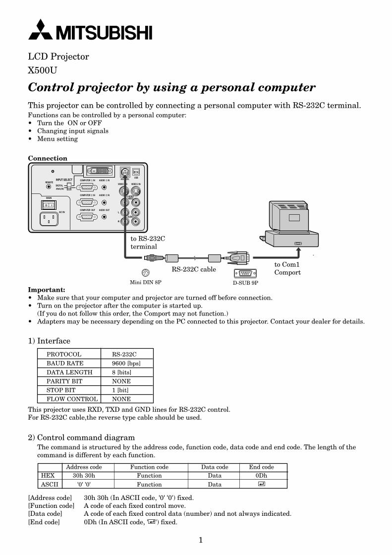
1
Control projector by using a personal computer
1) Interface
This projector can be controlled by connecting a personal computer with RS-232C terminal.Functions can be controlled by a personal computer:• Turn the ON or OFF• Changing input signals• Menu setting
Connection
to Com1Comport
to RS-232Cterminal
RS-232C cable
D-SUB 9PMini DIN 8P
REMOTE
AUDIO 2 INCOMPUTER 2 IN
AUDIO OUTCOMPUTER OUT
AUDIO 1 INCOMPUTER 1 IN
DIGITALANALOG
INPUT SELECT
MAIN
AC IN
O I
L
R
S-VIDEOVIDEO
AUDIO
VIDEO 1 IN VIDEO 2 IN
USBRS-232C
Important:• Make sure that your computer and projector are turned off before connection.• Turn on the projector after the computer is started up.
(If you do not follow this order, the Comport may not function.)• Adapters may be necessary depending on the PC connected to this projector. Contact your dealer for details.
PROTOCOL RS-232CBAUD RATE 9600 [bps]
DATA LENGTH 8 [bits]PARITY BIT NONESTOP BIT 1 [bit]FLOW CONTROL NONE
This projector uses RXD, TXD and GND lines for RS-232C control.For RS-232C cable,the reverse type cable should be used.
2) Control command diagramThe command is structured by the address code, function code, data code and end code. The length of thecommand is different by each function.
Address code Function code Data code End codeHEX 30h 30h Function Data 0DhASCII '0' '0' Function Data
[Address code] 30h 30h (In ASCII code, '0' '0') fixed.[Function code] A code of each fixed control move.[Data code] A code of each fixed control data (number) and not always indicated.[End code] 0Dh (In ASCII code, ' ') fixed.
LCD ProjectorX500U
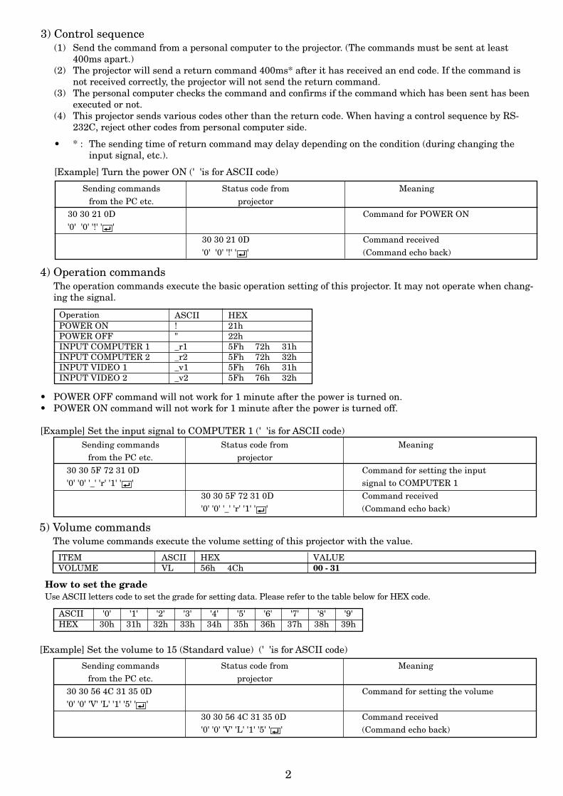
2
3) Control sequence(1) Send the command from a personal computer to the projector. (The commands must be sent at least
400ms apart.)(2) The projector will send a return command 400ms* after it has received an end code. If the command is
not received correctly, the projector will not send the return command.(3) The personal computer checks the command and confirms if the command which has been sent has been
executed or not.(4) This projector sends various codes other than the return code. When having a control sequence by RS-
232C, reject other codes from personal computer side.
• * : The sending time of return command may delay depending on the condition (during changing theinput signal, etc.).
[Example] Turn the power ON (' 'is for ASCII code)
Sending commands Status code from Meaningfrom the PC etc. projector
30 30 21 0D Command for POWER ON'0' '0' '!' ' '
30 30 21 0D Command received'0' '0' '!' ' ' (Command echo back)
Sending commands Status code from Meaningfrom the PC etc. projector
30 30 5F 72 31 0D Command for setting the input'0' '0' '_' 'r' '1' ' ' signal to COMPUTER 1
30 30 5F 72 31 0D Command received'0' '0' '_' 'r' '1' ' ' (Command echo back)
Operation ASCII HEXPOWER ON ! 21hPOWER OFF " 22hINPUT COMPUTER 1 _r1 5Fh 72h 31hINPUT COMPUTER 2 _r2 5Fh 72h 32hINPUT VIDEO 1 _v1 5Fh 76h 31hINPUT VIDEO 2 _v2 5Fh 76h 32h
4) Operation commandsThe operation commands execute the basic operation setting of this projector. It may not operate when chang-ing the signal.
• POWER OFF command will not work for 1 minute after the power is turned on.• POWER ON command will not work for 1 minute after the power is turned off.
[Example] Set the input signal to COMPUTER 1 (' 'is for ASCII code)
5) Volume commandsThe volume commands execute the volume setting of this projector with the value.
[Example] Set the volume to 15 (Standard value) (' 'is for ASCII code)
Sending commands Status code from Meaningfrom the PC etc. projector
30 30 56 4C 31 35 0D Command for setting the volume'0' '0' 'V' 'L' '1' '5' ' '
30 30 56 4C 31 35 0D Command received'0' '0' 'V' 'L' '1' '5' ' ' (Command echo back)
ITEM ASCII HEX VALUEVOLUME VL 56h 4Ch 00 - 31
How to set the gradeUse ASCII letters code to set the grade for setting data. Please refer to the table below for HEX code.
ASCII '0' '1' '2' '3' '4' '5' '6' '7' '8' '9'HEX 30h 31h 32h 33h 34h 35h 36h 37h 38h 39h
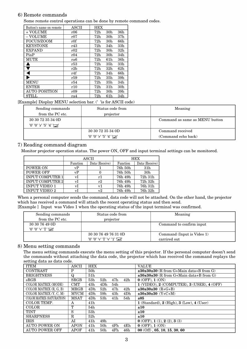
3
Sending commands Status code from Meaningfrom the PC etc. projector
30 30 72 35 34 0D Command as same as MENU button'0' '0' 'r' '5' '4' ' '
30 30 72 35 34 0D Command received'0' '0' 'r' '5' '4' ' ' (Command echo back)
[Example] Display MENU selection bar. (' 'is for ASCII code)
Button's name on remote ASCII HEX+ VOLUME r06 72h 30h 36h– VOLUME r07 72h 30h 37hFOCUS/ZOOM r0f 72h 30h 66hKEYSTONE r43 72h 34h 33hEXPAND r02 72h 30h 32hPinP r04 72h 30h 34hMUTE ra6 72h 61h 36h r53 72h 35h 33h r2b 72h 32h 62h$ r4f 72h 34h 66h% r59 72h 35h 39hMENU r54 72h 35h 34hENTER r10 72h 31h 30hAUTO POSITION r09 72h 30h 39hSTILL ra4 72h 61h 34h
6) Remote commandsSome remote control operations can be done by remote command codes.
7) Reading command diagramMonitor projector operation status. The power ON, OFF and input terminal settings can be monitored.
ASCII HEXFunction Data (Receive) Function Data (Receive)
POWER ON vP 1 76h 50h 31hPOWER OFF vP 0 76h 50h 30hINPUT COMPUTER 1 vI r1 76h 49h 72h 31hINPUT COMPUTER 2 vI r2 76h 49h 72h 32hINPUT VIDEO 1 vI v1 76h 49h 76h 31hINPUT VIDEO 2 vI v2 76h 49h 76h 32h
Sending commands Status code from Meaningfrom the PC etc. projector
30 30 76 49 0D Command to confirm input'0' '0' 'v' 'I' ' '
30 30 76 49 76 31 0D Command (Input is Video 1)'0' '0' 'v' 'I' 'v' '1' ' ' carrired out
When a personal computer sends the command, data code will not be attached. On the other hand, the projectorwhich has received a command will attach the recent operating status and then send.[Example ] Input was Video 1 when the operating status of the input terminal was confirmed.
8) Menu setting commandsThe menu setting commands execute the menu setting of this projector. If the personal computer doesn’t sendthe commands without attaching the data code, the projector which has received the command replays thesetting data as data code.
ITEM ASCII HEX VALUECONTRAST P 50h ±30±30±30 (R from G+Main data+B from G)BRIGHTNESS Q 51h ±30±30±30 (R from G+Main data+B from G)sRGB SRGB 53h 52h 47h 42h 0 (OFF), 1 (ON)COLOR MATRIX (MODE) CMT 43h 4Dh 54h 1 (VIDEO), 2 (COMPUTER), 3 (USER), 4 (OFF)COLOR MATRIX (R, G, B) MRGB 4Dh 52h 47h 42h ±30±30±30 (R+G+B)COLOR MATRIX (Y, C, M) MYCM 4Dh 59h 43h 4Dh ±30±30±30 (Y+C+M)COLOR MATRIX (SATURATION) MSAT 4Dh 53h 41h 54h ±05COLOR TEMP. A 41h 1 (Standard), 2 (High), 3 (Low), 4 (User)COLOR T 54h ±10TINT S 53h ±10SHARPNESS R 52h ±10IRIS AI 41h 49h 0 (OFF), 1 (1), 2 (2), 3 (3)AUTO POWER ON APON 41h 50h 4Fh 4Eh 0 (OFF), 1 (ON)AUTO POWER OFF APOF 41h 50h 4Fh 46h 00 (Off) , 05, 10, 15, 30, 60
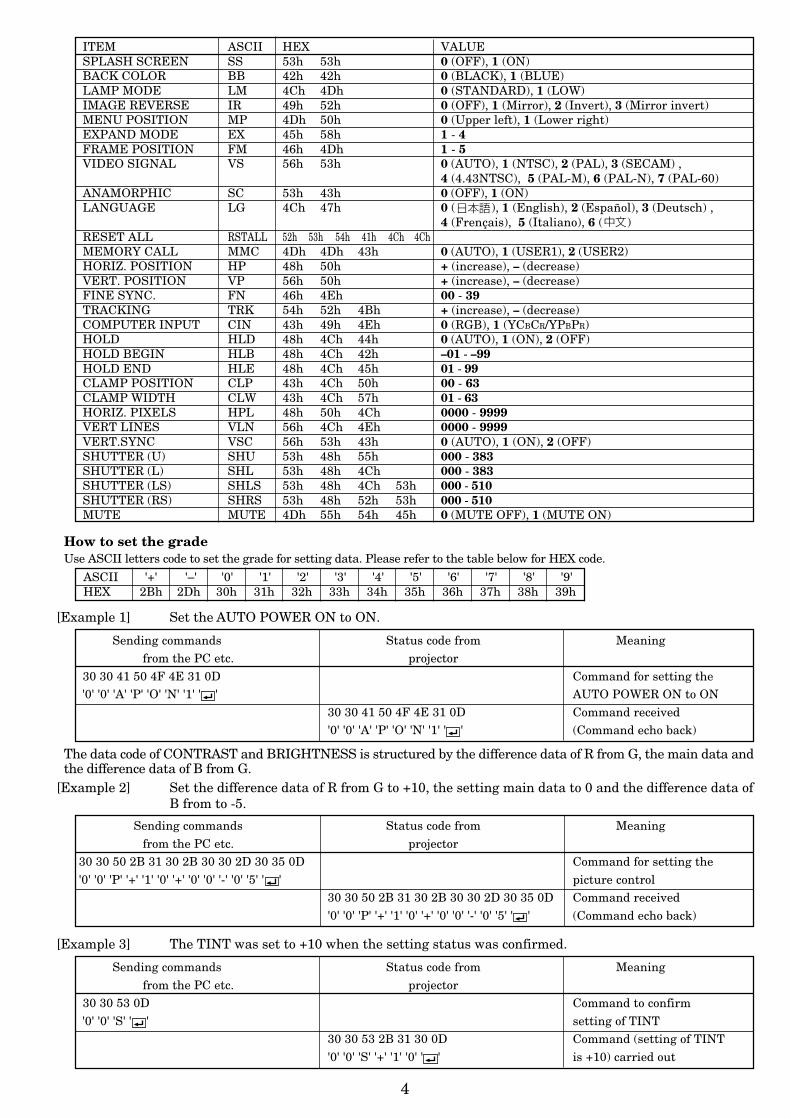
4
ITEM ASCII HEX VALUESPLASH SCREEN SS 53h 53h 0 (OFF), 1 (ON)BACK COLOR BB 42h 42h 0 (BLACK), 1 (BLUE)LAMP MODE LM 4Ch 4Dh 0 (STANDARD), 1 (LOW)IMAGE REVERSE IR 49h 52h 0 (OFF), 1 (Mirror), 2 (Invert), 3 (Mirror invert)MENU POSITION MP 4Dh 50h 0 (Upper left), 1 (Lower right)EXPAND MODE EX 45h 58h 1 - 4FRAME POSITION FM 46h 4Dh 1 - 5VIDEO SIGNAL VS 56h 53h 0 (AUTO), 1 (NTSC), 2 (PAL), 3 (SECAM) ,
4 (4.43NTSC), 5 (PAL-M), 6 (PAL-N), 7 (PAL-60)ANAMORPHIC SC 53h 43h 0 (OFF), 1 (ON)LANGUAGE LG 4Ch 47h 0 ( ), 1 (English), 2 (Español), 3 (Deutsch) ,
4 (Frençais), 5 (Italiano), 6 ( )RESET ALL RSTALL 52h 53h 54h 41h 4Ch 4ChMEMORY CALL MMC 4Dh 4Dh 43h 0 (AUTO), 1 (USER1), 2 (USER2)HORIZ. POSITION HP 48h 50h + (increase), – (decrease)VERT. POSITION VP 56h 50h + (increase), – (decrease)FINE SYNC. FN 46h 4Eh 00 - 39TRACKING TRK 54h 52h 4Bh + (increase), – (decrease)COMPUTER INPUT CIN 43h 49h 4Eh 0 (RGB), 1 (YCBCR/YPBPR)HOLD HLD 48h 4Ch 44h 0 (AUTO), 1 (ON), 2 (OFF)HOLD BEGIN HLB 48h 4Ch 42h –01 - –99HOLD END HLE 48h 4Ch 45h 01 - 99CLAMP POSITION CLP 43h 4Ch 50h 00 - 63CLAMP WIDTH CLW 43h 4Ch 57h 01 - 63HORIZ. PIXELS HPL 48h 50h 4Ch 0000 - 9999VERT LINES VLN 56h 4Ch 4Eh 0000 - 9999VERT.SYNC VSC 56h 53h 43h 0 (AUTO), 1 (ON), 2 (OFF)SHUTTER (U) SHU 53h 48h 55h 000 - 383SHUTTER (L) SHL 53h 48h 4Ch 000 - 383SHUTTER (LS) SHLS 53h 48h 4Ch 53h 000 - 510SHUTTER (RS) SHRS 53h 48h 52h 53h 000 - 510MUTE MUTE 4Dh 55h 54h 45h 0 (MUTE OFF), 1 (MUTE ON)
How to set the gradeUse ASCII letters code to set the grade for setting data. Please refer to the table below for HEX code.
ASCII '+' '–' '0' '1' '2' '3' '4' '5' '6' '7' '8' '9'HEX 2Bh 2Dh 30h 31h 32h 33h 34h 35h 36h 37h 38h 39h
[Example 1] Set the AUTO POWER ON to ON.
[Example 2] Set the difference data of R from G to +10, the setting main data to 0 and the difference data ofB from to -5.
Sending commands Status code from Meaningfrom the PC etc. projector
30 30 50 2B 31 30 2B 30 30 2D 30 35 0D Command for setting the'0' '0' 'P' '+' '1' '0' '+' '0' '0' '-' '0' '5' ' ' picture control
30 30 50 2B 31 30 2B 30 30 2D 30 35 0D Command received'0' '0' 'P' '+' '1' '0' '+' '0' '0' '-' '0' '5' ' ' (Command echo back)
Sending commands Status code from Meaningfrom the PC etc. projector
30 30 41 50 4F 4E 31 0D Command for setting the'0' '0' 'A' 'P' 'O' 'N' '1' ' ' AUTO POWER ON to ON
30 30 41 50 4F 4E 31 0D Command received'0' '0' 'A' 'P' 'O' 'N' '1' ' ' (Command echo back)
The data code of CONTRAST and BRIGHTNESS is structured by the difference data of R from G, the main data andthe difference data of B from G.
[Example 3] The TINT was set to +10 when the setting status was confirmed.
Sending commands Status code from Meaningfrom the PC etc. projector
30 30 53 0D Command to confirm'0' '0' 'S' ' ' setting of TINT
30 30 53 2B 31 30 0D Command (setting of TINT'0' '0' 'S' '+' '1' '0' ' ' is +10) carried out


