C.P$!B; 230 A.R.C. Technical Report A.R.C. Technical Report MINISTRY OF SUPPLY AERONAUTICAL RESEARCH COUNCIL CURRENT PAPERS Devel&nent of an Air Mass-Flow Rate Meter W. J. G. Cox, A.M.I.E.E., A.M.A.I.E.E. LONDON: HER MAJESTY’S STATIONERY OFFICE 1956 PRICE 4s. 6d. NET
The Llevelopent of an Air >iass Flow rate mter to oowx n wry wise range 1s describea which, ensertially WI analogue computer, sves a two- sweep pointer direct prescnta%ion of sir mass flow rate, indepelldent of pressure, tompereturc and velocity changes within the range of the instzw- mont. The pointers are driven by a servo system which is error-actuated from the computing briec network, secondly feedbackbeing employed to maintain stability wzth n saturated angular output rate of apprsrJmatelJ 330 per scoond.. Specifkoatlons orid perfarmanoe figures are given for the mdivxdud transduoor e1ement.s snfi the complete indrument, error estimations ore made, and the servo stability is 6iscusscd.
-l-
1 IdrWluction
2 XWnciple of iieasuroment
3 tiethod of Moaswement
4 l?escrlption
4.1 General 4.2 Static Precsvre TranSduCCr
&3 uynamic Pressure Transduoer 4.4 Temperature Suwrtive Element 4.5 Dial Plate, Szvomotors and Srive hssex5ly 4.6 ~leotricalC:ontrols Fancl b -! Power Fack
5 2ontrol Scheme 5.1 Description 5.2 Functioning
6 Desxgn Consideration3 6.1 General 6.2 Computmg Bridge
Transient Behaviour of Servo System (without faedbaok)
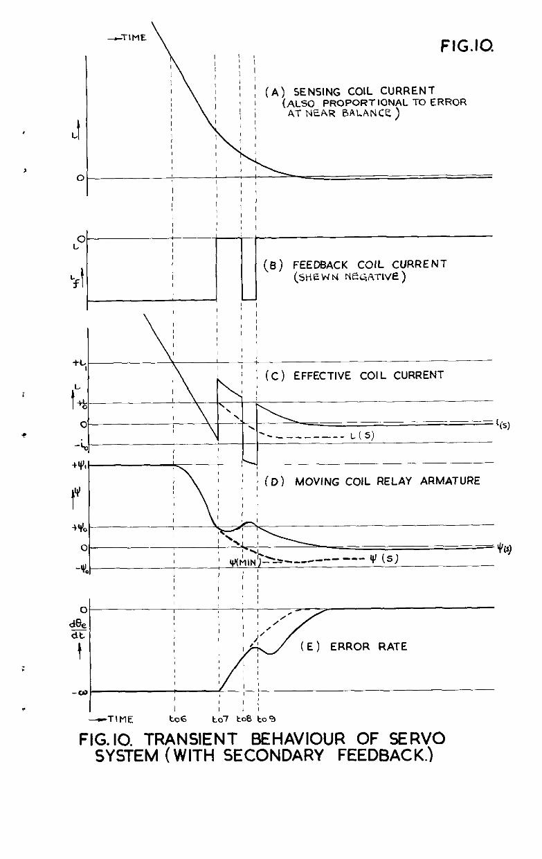
Transient Behuviow of Servo System (with i'eedback)
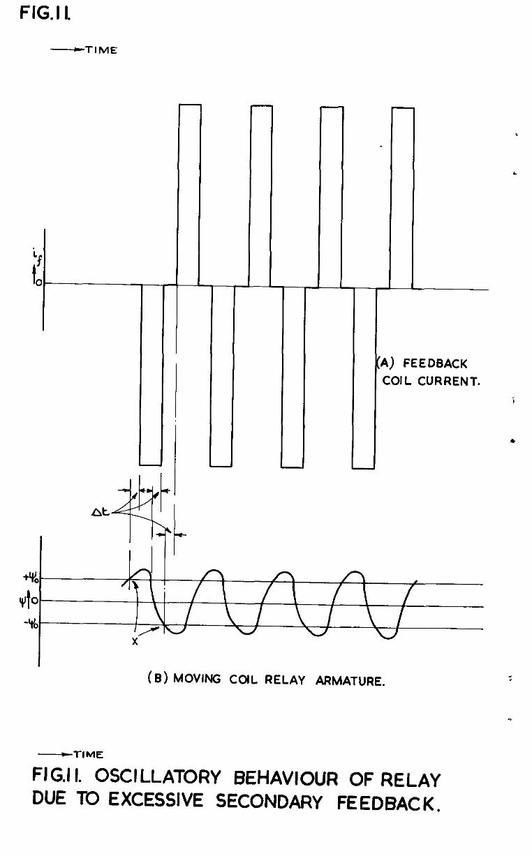
OsciSLatory Behaviour of Relay due to Excessiw I'edbaok
Recording of Servo System Behaviour (without fee%%ack)
Recordzing of Servo SystemBchavior~ (with feedback)
Platuwm Irqact Type 'Wirpcrature Bulb - Variation of Resistawe with Tcmpere.tur~
Statio Pressure Transducer - Variation of Rosistanoe with Pressure
Dynamic Pressure Tmtklumr - Variation of Resistance with Pressure
Caloulated Characteristic of the 'X1 Indicating Xesisiznoe (Id? Range Section)
Calculated &araotcristx of the 'X' Idioating Resistance (Hig!l Range Seotion)
Diap~am &swing Error Dic.tribution at Changeover Position of the *X1 Traoks
Estimated Total lieximm Error of Nass Blow Rate idication
1
2
3
4
5
6
7
a
9
10
11
12a
IZb .
16
$7
18
$9
-J-
1 Introclu.ct~on
The measurement of small air mass flo-ti rate:: w be readily achieved by severalmethcds. "or instance the angdxr deflection of a swug plate located zx the sirstream is related to mass flow rate, or,alternatively, If a Inow small heat ener6)i input in the air strean causes a measurable temperature ruse, then the mass flaw rate can be assessed fmm lclovm specific heat values, as II). the instrument &scr&ed in reference & But the measurement of larger air mass flows cannot be assessed accurately by these mwns, and the nekl for an mstrwent giving a dirwt mass flow rate indication over tha wide ranges used in ~a.? turbine and compressor work has led to the &velopmcnt of the instrwcnt &scribe& hero&
It was ovi&nt tlia: t& d%-act mccoring of lsrge amouLts 3f air wa5 not n practical _sroposrtior,, end c0nsequentl.y atwntion was turned to measuring the dependent pressure s an& temperature sf the moving air, and corralirt%ng these m one instrumentation scheme to give the reqtied mass f Low rate.
2 l'rinclple of dwxurcment --I
In an air stream, if 'Y is the static pressure absolute, 'Tr is the <abso1ulz tempcdxre, 'p' and Iv' the density and velocity respectively, and '3' is the dynado pressure rzze shove the statio, then from the gas equation: -
t
and as
P = a constant, P
p or P"F
D = pv2, ,3 then v=P - 0
But the mass fiors rate
an& substitution for 'p' results in:- &
id o: 22 0 T
(1)
(2)
(3)
giving tine mass flow rate in terms of measwablc pressures and tcmpexature wxthlr the limits of applicatLon of the laws stated above. mi.s xas agx&i as an exprwsion likely to Live a practical mass flow rate inai- catton mnth roasonablc accwa~y >fhtin trnsf'o~d into instrumsnt andogies. Overall l&its wrc accord ostablish2d as follows: -
P . ..*..... s, G to 90 p. s. i. abso1utc
D . . . . ..."... 0.2 to 9 p.s.1. tifcrcntial
T . . . . . . . . . . . 2% to 612%
3 not greater thm 0.1
and accuxacy of fhr idicat~on was required if possibl% to $, though up to $ u~ould be acceptCole, these peroentages beixg of the actual indicated
-4-
quantity, and not of the lO$ value. Thus the expression F varies over the range I.96 x IO+ -3 to 21310 x 10 , rind its square root over the range 0.0442 to 1.65.
A four-bar linkage waa tho first method tried, the variables 'P, 'D' and 'Tp' being converted into "1o.g" rotetlons, clifferentials beizg used to add and subtract, dth a final 'at?-log" linkegc to give the mswer. !Ene movencnt of the assemblies, however, was inadequate to cover the range requirct?, and the frictional and backlash cffccts mtroduced errors too loge to be acceptable.
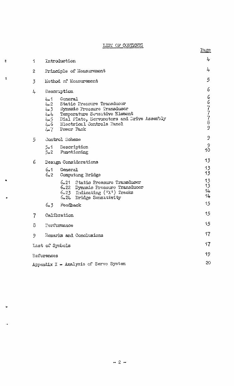
It was then deoicicd that an clectricalmethcd for obtaim, the relationship (4) given c,bovu, over the wide rcnge xquired, would be more practioiible thm nechanioal means. Tnerc are seserd potentiometer nct- ;:orks dich give either a voltage or current o&p& proportional to the prddct of tiio rcsiskncer, and inversely ~oportiond to a Q&.-d resis- tance, andb;: maEa suitable trans&mers for converting VI, ?I)', and IT' into proportional resistances in the nckork, a square root soele on the output voltage or current ind?.oator will indicate mass flcnr rate directly. %cre is also the convcntio~~al~ivhcatuto~le bridge arrangement of four rcsistanoes, which, when balanced has one arm proportional to the ;xoduct of the adjacent two resistarlces and inversely proportional to the fourth, and here again the square root of the resistance value will tiicate mass flow rate. The potentiometer circuit3 suffer from tne dkdvantage that several in3ioators would probably bc reqkxxl to wvcr the rage, end stabilised current or voltage sources vroLJd be necessary, 33.~0 f'unct~oning over a tie range. l'he brdge cxccuit by comparison gives a balanced idication independent of applxd voltage, 3x8 the final presentation, being the representatron of a varying resintancc, offers greater scope for scale extension than the current or wltage indication required by the potentiometer circulto. It 7~s therefore decided to une the bridge osransement, anit ?igurc 4 gives a diagrammatic represcntatlon of the scheme adopted.
3 - Xethcd of measurement -
The computxng network concxt s essentially of four resistances as shown, arrange6 as the ar&s of a Kheatstone bridge. The static pressure in the tiucting is ccoll~iunicated to the Static. Pressu;-e Transducer, which is a pressure-tight ohber oontaining an evacuated spring loa&d metallic bclloms. I:ss~.ming a constant spring rate, the free end of this bellows moves in proportion to any change in the absolute static pressure and this movement is m&c to operate a variable resistance also housed inside the cwer. This resistance, odlcd 'A', forms one em of the bridge and. varies therefore proportionaliy with the static absolute pressure.
The dynmic pressure dif?f'erentml exx 'sting between the pitot t&e s.nd static is connected to a second pressWe-Id&t chadcr, the J;ynaAc Pressure Transducer. ikc diffcrentinl pressure nets acros3 a spring- loadd mtallzc bellows, the zwvement of vrhich operates a variable rcsis- tance 'Cl m a s5.mk.r fanner to the statx pressure transducer. This resistance 'C' therefore vales pmpor'cionally with the Fiynmio pressure CS.ffcrcr.tial, and forms the brike e.m opposite to 'Al.
The third arm of the brdge called Y3' conointn of a length of platlnuu atie imerscd in the az.r strcm to scntijo CalTJ tcmpora tore var.& tiona, any such &an:-.a;, resulting 52 a nearly proportimal resistance change of the vrZre aver the limited range in use.
1%~ fourth am of the 'midge is the "zns~er" mu called 'X', and with the bri@e balanced the well knm~ relationship gives:-
-5-
x=+ = 7 x a constant 2 = I< x a constant .
1 The balanced value of the arm Ii;' which, as shown shove, varies pro- port~onallg with the square of the mass flow rate, 33 varied automatically by a servo mechanism which in turn responds to the out-of-balance error signal across the bridge arising from sny variations of 'Al, IBl or 'Cl from the balanced condition. The servo tends to alter 'X1 back into a balanced position where the error signal is reduced to aero and 'X' again infixates U2! . The rest-tance 'X' 1s wound m the form of tie Worm Y toroids, variation being obtained by using contact wiper arxs rotatable <'vsr the ~KIrulgs. Attached to each v&or arm spindle is a pointer, the angular nisplaoement of which (when the bridge is balanced) is proportlanal to 1x1 or, 221 other WordS, to 'i12' L 3~ making tbse painters move over a sqmre root scale tine final steady state ~~dxatlon of 'CC' or 'M i3 obta%ned d-ircctly. The two torox3e.l tracks 5nto which '2;' has been wound form an xxtcnded rango, the one wvenng ana&proxGate range of 2.5% to 2C30 and the other from ZC$ to 1G@ of full scale. Associated with each track I.S its ~irn tiicator pointer, scale, and servo motor, with auto- matic 15mi.t switch transference between the tracks so that the servo system can seek to establish a balance point over both tracks. This tam sweep preaentat~on enables the requ5red range to be covered r-iith3.n a reason&la dial dimension, and gives adequate "retiility" at the low end Of the scale.
J 4 Dcscriution
4.1 Gcrwxl
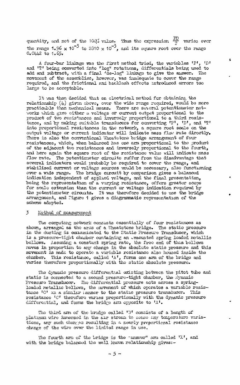
Figures 2, 3 and 4 give general views of the instrument with the * covers removed. The components arc mounted wathin a rectangg alloy-
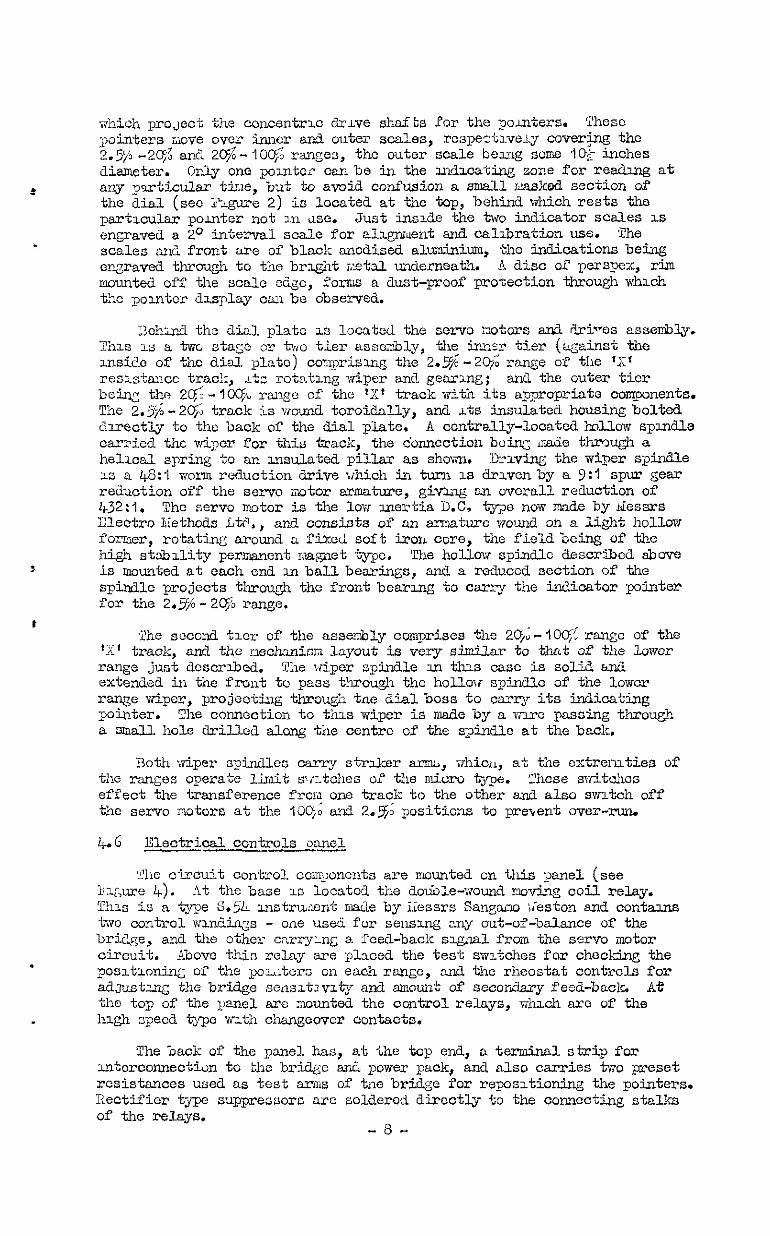
angle frame, the front end of which carries the display dial and indi- cator pointers. Iiounted off the rear of the dial plate are the servo motor esse~~bl~co wxth their gear and. worm drives to the 'ii* tra&s and display pointers. Eehlnd this asocr&ly are mounted the static and dynamic prcnsure transducers housuy the varisble resistance mech%i.sms resmnsive to the stat3.c and a;namLc pressures respectively.
Located on the r@t hand sde is an "eleotrical controlss" panel, on whach IS mounted a double-wound no- ooil relay (responsive to error signals from the main computing brae), the preset test oontcol switches, feedback and sensitivity controls, and all the relays necessary for the serve system operation.
The powor supply pack 1s located at the rear end of the frame and wntains a step-down transrormcr, secttiiers and soothing condensers for supplylymg eiectricaIL power to the bridge network and servo mechanism control cxrcu&ry. The illustrations also show a sub-panel munted above the power pack and carrying two pressure~gauges regxstcruy the @nwni.c and static pressures. These are for 'cost purposes only and are not part of the instrument.
4.2 _I Static ?u'essure tixnsdutxr
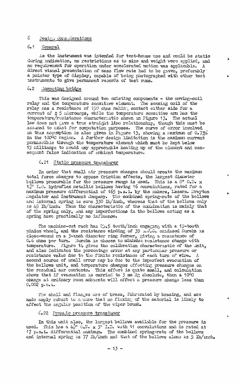
Figure 5 illustrates this transducer. The entire mechanism is oon- taxned mithln a cylindrical pressure shell of brass, vtith flanged and bolted end plates, the dntcrior asseaibiybeing pillar-mounted off the base-plate flange. An e-racuatcd anf! sealed metziUi.c bellows (containing an urn- compzss+n [email protected] coaxial with the bellows) is located betxeen "he pillar supports, and 1s secured to the base-plate by three individual clap in order to 2%cilitatc IinAng-up.
-6-
The upper free end of the bellows acscmbl~ carr1c5 a pmh-rod which IS coaxial with the bellows, and is located bekzeen upper and lower guide rOllerS, ensuring that only linear vertioal motion of the bellows and push-rod takes place. T-k middle section of the push-rod is formed into a rack which engages with a plnlon shaft, in turn mounted at each end on , ballbearings. This pnion shaft carries a clsnped tiper arm assernblJ whzch makes contact with, ard moves over, the inner surface of a torod resistance track. This resistance forms the '~1' arm of the bridge, and
S is carried in r;n insulated ring housire, the centre of which LS coincident with that of the pinion shaft. The wiper arm contact is insulated from the sxm, an6 connection is made tlwcqb a hire passing through a hole drilled do%m the centre OP the pinion shaft.
Lll the electrloal connections are led t!irou& hermetic ceramic seals soldered u-ho the base plate. L vibrator assembly comprising a srmll motor anii eccentrically-mounted mass 1s shown fixed adjacent to the pinion shaft, and was u~itialljr i'itted in case the ntiotion between the wiser brush and track s:lould pmve to 5e excesclve and saze vibration be require& to free the motion. After tests, ti{ever, It was eviilcnt that vibration would not be rcqu~kercd.
4-3 Dynsmio presLncc transducer
This wit is shcwm in Figure 6. As in the cane of the static pres- sure transducer, a cylkdrical brass shell vrlth flanged and bolted end plates forms the p?.esswc-tight cort&cr for the mechanisz The static pressure 1s communicated tc tkis shell which also ooLlta5ns an Lnner housing for a spring-loaded metallic bellows. The bellows is 3oldered around its top edge to this -er housing, the bottom end of the bellows ‘
bezng free to move vertically. The dynamic pressure 15 connected to the inrer housirg an6 acts on the outside of the bellows to move the bottom upvmxds against the static pressure acth instic the bellows. 1
A puck rod extan& f'rom tie b&tom of the belloiis u;, through a large clearance hole &I the top of the UTner hous*, and terminates in a rack profile. Loller g.zi&s ~u'e erran@ aLong the length of the pu,sh-rod to ensure that t73iL.y vertical motion only 18 ;>ossible. T1.e rack engages with a puion sltit, ball-bearing r;munt& as shots, which in a similes plsnner ta the static pressxc trandiucer carries a wiper arm, capable of moving over the timer surface of a toroidal resistance traol:. This resistance forms the 'Cl ar;n of the main bridge. h3 prev~isljr descrtied, hermetic c~:ramic seals pasasnin~. tkrough the she'll arse used to enable exter- nai eleotrlcal connections to be made.
4.4 Tompcrature scnsitlvc element
The element used. in the air duct is the stnndar& impact bulb type IT 3-2. This element is of platirnn? drc iroutd over an open insulated former and is presented adally to the azx stream. II tubular sl~oud with a frontal opening s.moun&s the element, and the aizr passitll; over the element escapes through small side holes at the rest erd of the shroud. These holes are sized so tkat total stagnation of BLT around the element is avoided vdthout permitting a I&h enough sped to intrcduce an appre- ciable velocity head error. For temperatures bigher than some 32oOC the
*
insulation of the standard henii is modified to mm suitable hQh tern- perature material.
4.5 Dial plate. servo <:otors sn?! drive asoe:Hy
?igure 7 F;ives a general view of this ass&Q. The dial. plate is of light alloy and oarries in the front a central bossed opening through
-7-
t
.
which pro JeCt the concentric drive shafts for the pomters. SThesc pi.nters i.io~e ovczc ~IUXX and outer scales, rcspe~tlve~y caverjng the 2.576 -2c$ an& 2c$-"10% ranges, the outer scale beeng some ?O,- inches diameter. oray one pomter can be in the u&cating zone for reading at any ~9rticular ttile, but to avoid ooni%.sion a small mask& section of the dial (see Zc'lgu~e 2) is locate& at the top, behind which rests the particular pointer not 111 use. Just ins~3e the two in&icator scales 1s engraved * P interval scale for ale.grvtient and calibration use. 'The scales ,a& front are of black anodised aluminium, the indications being engraved throu& to Yne bright i~eetal underneath. A disc of perspex, rim mounted off the scale edge, forms a dust-proof protection through uuhlch the polntcr &splay can be observed.
3ehir.d the dial plate is located the servo motors end iFriW% aasembl;y. Tnls 3.3 a two stage or %UO tier assembly, the inn2 tier (against the uk.cio of the di-11. Plato) ooqrismg the 2.$-2@; range of the 'XT resrskncc track, ~tc rotntmg ~&per and geerxflg; and the outer tier beiq the ZC$-lK$ range of the IX' track with 5ts appropriate coqonents. Tne 2.57$-2$9 track is wound tomidally, and rts insulated housing bolted &rectly to the back of the tial plate. A centrally-located hAlovr spmdle carried the wiper for this track, the connection bcirq made tkmugh a hellcal spring to an insulated pillar as sholm. Driving the wipr s~ind.le 1s a @:I worn reduction drive lihich in turn 1s drlvenby a ?:I spur gear r&J&ion off the servo motor armature, giv&ng an overall reduction of 432:l. The servo motor is the low mertia D.C. tiJ2e now ma3.e by ~Lessrs Clectro itethods US,, 3n.d consi3ts of an amature wound on a light hollow former, rotatiq around a fixd soft iron core, the field being of the high stabbllity permanent magnet type. The hollovi spindle described above is mounted at each end en ball bearings, and a reduced section of the spindle projects throu& the front bearuy to carry the iru?jcator pointer for the 2.5-2oC,5 range.
'The second txr of the assembly comprises the 2C$-loo;': rango of the 'IX' track, and the meclmnisn layout ia very si0lila-r to that of the lower range just dcscribod. 'The wiper spindle u1 &s case 5s solid and extended in tine front to pass tlbrough the hollow spindle of the lower range wiper, projecting through tae dial boss to carry its indicating pointer. The connection to tills wiper is made by a KWC passing through a mall hole drilled along the centre of the spindle at the back.
Both wiper sptilen carry streaker army> rrhicn, at the extrermties of the ranges operate limit si:tches of the micro t-m. Zhese sVsitchos effect the Isansference from one track to the other and also slatch off the servo motors at the IO& and 2.$ positions to prevent over-run.
4-+6 Electricd. controls panel --
'?he c'zcu5.t control coqoncnts are mounted on this panel (see 1 l~um 4.). At the base 1s locstcci tne double-wound mz&ng coil relay. This is a type S.5L. mstru:lent ma& bjrijessrs Sangkzo ireston and contazurs two control wlndiqs - oae use6 for seusug my out-of-balance of the bri?,c;e, ati the other cra~ycynly, n feed-back sqaal from the servo motor circuit. Above thin relay are placed the test switches for checking the posstloninC, of the potters on each ran&c, and the rheostat controls for adjustuy the bridge sensltlvlty <and amount of secon&ry feed-bacla At the top of the panel are mounted the control relays, whloh arc of the hqh speed type wz~th chengeover contacts.
The back of the panel has, at the top end, a terminal strip for mterconnectidn to the bri.&e and power pack, and also carries two preset resistances used as test iirills of tile bridge for reposition the pointers. I?ectifier type suppressors are soldered directly to the conoecting stalks of the relays.
-8-
4.7 Power pack
A stanan& service type gower transformer with multi-&e-&own win&ings supplies electrical power for the circuitry. The mains tiput win- is suitable for 230/250 volt, tingle phase, 50 cycles A.C. t Selenium type half-mave rectifiers with electrolytic smoothing condensers provide individual smoothed L.C. inputs to the bridge <end control. circuit respectively, aad also include.3 is a separate rectified and sx3-tched I supply for the vibrator motor of the Static Pressure Transducer mentioned in paragaph &2.
5 Control Scheme
5.1 Description -
'pile rhxing diagram of the contiol scheme is shovm in E'igWe 8. As already ex$laincd, tne main brtige is comprised of the variable resis- tanccs 'A' 'Br and 'C' (responsive to static pressure, temporaturc and dynamic pr&sure respectively) and the servo driven veriablc resistance 'X1, the value of which is indicate?i by the angular position of pointers a&, when balanced, gives the mass flow rate answer. In series with each of the TA', Id' and '2' resistances are small padding resistances, the values of -&xh are arranged to briq the calibration lines through the true origii (see Figures 13, 14, 15). A three-pole changeover "test" svtitch is fitted so that in the "normal" position the retisbncea 'A', Y$* and 'C' are ir cucuit, while ;n the "test" position pre-set resis- tames are switched in making a definite balenced value of 'X' available for repositioning of the potiters. 21 "test range selector" snitch oper- ates on one of the pro-set resistance s making this balanced value posi- * tion available on both the hi& and low ranges.
Ibe supply to the brae 1s taken through the Vrcc" en3 of the 'X' t arm so that a proSresso.vely hi&or resistance IS placed in series xith the bridge as it closes down to 1oiTer resistance levels, and ton& tc counteract the increasing scnsztivity of the bridge. At the lower end of the high rage IXf track the sensitivity requires stall further reduc- tion, and a 4,700 ohm series resistance in this am, whxh i5 normally short-csrcuitcd, is placed in circuit by the openinx of a switch operated. by a stri;;er arm on the wiper of the hi& range track. When indication is switched to the "low rangc " IX* track, a range transfer relay Ho.3 is arrargcd so that its contacts change over the bridge supply f'ros the high r~c trac:c through to a pr=-" c -et sensitivity control variable rcs~s'ance in series with the low razyo track. The one scttmg of this control is found adequate for al.1 positions in the low range, as here the rate-of- change of resistance is much less than that of the high range tracl;
The bridge out-of-balance is sensed by a moving coil relay. This is a type 5.54 relay mile byi;essrs Sangamc Veston Ltd. The contact arrange- ment 1s a changeover one, with a central contact move3 by the ennature between two limiting fixed contacts. In tic central position vath no armatvrc current flowing the contacts arc open-circuited, and this posi- tlon ia held stable by the armature control spring. The wnnature is double-wound, one of the ~&dings (cdlled the sonsin; ceil) being con- s no&d across the Sri@ to sense any out-of-baWxt. If an out-of- balance current of th2 order of 5 ricro+~~ps flcws the armature is deflccte(i and contact m&e either one s%e or the other depending upon the direction of the ou~of-bal;x~cc ourrent. The second w~&ing (called the feedback ooil) obtains a pre -set controlled current only while either servo-motor is enorgisc3, an3 is arranged Ctirectionally so that it acts on tne relay ermatUrc m opposition to the sensing coil.
-Y-
t
The contacts cr tl-2 uo* Cal relay control two high speea relays, the "Increase" and Wecrease" relays respectively, the changeover contact6 of Tfhicn switch the supply on to the servo-motors d.2rectionally so that Wlt& the "Increase" relay "on", the servo-motor rotates to increase the 1:;' resistance, while opposite rotation occurs with tile "0ecreasc" relay "on". sot11 rczay3 carrot be energpsed shultmeously, and when de- energised the servo-motors are short-clmutcd. f!Ei@l & II lo,,q" 1st switches are wired into the "increase '1 aA "Decrease" relay coil oircuits. Those switches are open-c~cuited bv strrkers on the $per arms of the 'X1 resistance high snd low rengcs at the IOQi and 2.93 positions respectively, and prevent over-run of the servo-motors beyoti these limits.
Itang Transfer Switches sre loczated at the top end of the low range track and the bottom e.nd OP the high range track. These are operated by strikers on the wi&xor smns, ati control the high s?eod range transfer relays tc ensure that the *gpropriate servo-motor ohangcover sequence is ~bscrvc?. when runmq, through from one range to the other. Over the regron of operation of these switches the track winding resistance turns are shorted together so that tilt changeover action takes place without a charge of rcsistanoc of the 'Xr arm.
The Pee&back coil of tile moving coil relay is connected in series riith a controllrng resistance across the servo-motor supply and carries (I current only while the servo-motors arc energised, this current being reversed on rcvers21 of mtor rotat;on. As stated. above, the polarity of the fcedbaclc coil is arrenged in opposition to that of the sensing ooil.
5.2 3u-stioG.n~
!A an&ysis of the systom is given in Appendix I, and the fo&xing paragraphs give a verbal description.
Assutig for the mcmcrt that the feedback circuit is not connected, Figure 9 CLustrates the transient behaviour of the servo system com-
ponents when subJected to a step function input distxrbsnce. In this dlC+!JYU~ '02' 1s the inpUt or the desired angUe.r position of the 'X' track mpr ami, and 'Oo' 1s the output or actual angular position of the sra. (i'wqre 9a shows their transient behaviour.) '~3~' is the error, or difference be&en input and output, end is depicted in Figure 9b. Pqurc pc shotvs the ve.riatAon of the current in the moving coil relay sensing coil, and Pigurc gd the angular movement of the relay armatie. The contact arrangement consists of tire leaf springs fixed to the srma- ture and these constitute the mom contact. Fixed point contacts are located each side of the mwing contact so that a &splacement of f: Q. has to take place bcforc contact is made. Fnrthor displacement can take place between q. and *, vaiue:, on each side and over these regions the contact spring is being compressed. Lt the !: $4 positions the arma- ture stop prevents further movement outside those limits. Thumbnail sketches in ZLgwo PC? inarcnte ihe attitude of the armature at various
3.0 mstants. i'igrurc ye shows the rate of error correction, e
at '
?:xor to instant *'toI", the error, error rate and sensing ooil current arc assumea zero, v?th the br~C@c balanced and the relay armature central, and further msuzing that balance IS occurring on the high range, the low range scrvo-raotor- hll bc she tmP= 81,
r e out by Transfer Relay No.2 t d end Relay 20.1 xi.11 hold the hi& range servo-motor in circuit.
nt imtant ?Gl", me of the bridge arms is given a step change resulting in a sudden increase of Igi' to 3 new value, assi;med to be large. The unbaianoc of the briage result 6 in a sudden increase from zero of the
- IO -
sensing coil current, winch ileflects the ro.iay armature so that at mstsd ItO*' contact is nade at the '+$o' pu sition and the "Increase" relay 1s energised. This starts up the high range servo-motor which in turn moves the 'X' resistance track F&W and starts to increase 'go' up tows&z the 't3i' value. As shownby the Figure ye the servo-motor soon saturates to a constant npeed, giving a uniform error correction rate.
After 2.nitie.l contact at *to2* the relay amature further Ceflects untilbrou&t to rest against its stop at the 'I$?' position, and this position 1s maintained w:til the sensaug coil current (which is ?ro- gressivcly fLLlz.ng as error correctxon proceeds) falls to e value 'ill, which woul6 just maintain the relay armature deflection at '$1' in the steady state. lit this xnstant 't0~' the arolabre be&s to i%~ve back towards 8, central position, and at Cnstant 't%' again reaches the '+$o' position where contact 1s broken ad the "Increase" relay de-energised The serv9-motor 1s consequently short-circuitea at thi3 instant aniL rapidly 4ows down, pausing the ~'error" and sensing wil current to reach the ml1 steady state values n ' 'ee(s)' and 'i(s)' res-pectively.
The zoving coil relay armature also eventual& attains a steady state value '$(
4 * but a.3 It is sn indeptmdcnt spring-mass system assumed
critically dampe it ~3y also reaoh a '&in * value (less than l*(s)') at
t"Z 2$2e'35!l'take place to reituoe '6 1 If '+min* falls to the '-$T~' value a reverse correo-
* from its overshoot value. Thus M oscilla%ory condition of '6, ' is szt up, the atterxation af whxh will depend upon suc:l ftctorc as error rate and wldtln of tine *i~)~* to ‘“$0’ zone. TnPne criterion for this servo-system z.s that the ind.icated output 'go' should be xovta to Its new steady state value as quickly as possible but without any overshoot. These wnditions sre obviously ful- I filled if 'QEti' just falls short of the 'w$~' value, and WAS condition is achieved propessivoly from ?&e oscL!Ll.atory condition by decreasing the error correction rate an&/or inorcasing the 'i$o' to '-eo' zone width. . Llut increase of this zone width is undesirable as xt lesds to an increase in the indicated error for stew state corditions, a& for reducing; hysteresis of indication the zone vi&h should be kept to a minimum.
A seconckry feedback loop is intrcduccd so that the error correction rate canbe znorcnsed while r@zddning a mining tiea& zone snd still meet- the requirement for deadbeat 3ndicai;ion ti+&out overshoot. iQ&~e IO showo the typical transient behaviour of the system with feed- back in operation. A starting condition (prior to mstant 't06*) is assuzd. where a substantial error has been est&Lxshea, and error correc- tion x.s be% effected at the saturated rate. Yne @aphs for 'Bi', '13,' and *get have been omitted u1 lil,rrure IO, as these are al1 ltiesrly inter- dependent, an3 Tigurc 10s. shows the sensxng 00~1 current wluch, for small ~znbalanccs, 1s proportional to the error *ee*f Tile mdng dia&rsm shows the feed-back coil conncctei? throu& a controlling resistance in such a way that n constant current floras through it while any servo-motor is cnarg‘lsaa, this cUrrent changing in direction with reversal of drive signal to the Yervv-motors, Lind dr'o~zd& to zero ,;bx the moving coil relay con- tacts are open. This f^c&-‘3aCk coil current is shovm in i?i@re lob, ald bcisxg noun4 in o~~siZon to the scnsing coil, the vector ad&Con of these cod currents (to swile) produces sn "effcctivc" coil current &own in Figure 100 to xrhich the relay armature is rcsponsivo. 8
!.t ulstnnt 't06' the effective coil current has fallen to the '+i,' value and the relay &?xnature commences to move away from the 't$j'stop. At instant 'to-/' the arLatidre has deflected to the '+qo' position where
.
the sel??o-motor is stitched. ofP and short circuited to retd the error correction rate. Al30 at instant 't
Oi * the fedbnck coil current is
reduced to zero, @.vi.ng a step iacrea e to the effective coil current ta * See equation$39,, &pen&ix I
-
- 11 -
a valxe equd te tl?e sensmg COll current. hs this v0.1~0 Wjr be substan- txill- above the (+L~~ val;ie (as shorn ), the relay armature mvement is reversed and def'lected'back tomrds the '+$I' region, reaching the '+$o' position at some instant 'tOBf. Here the servo-inotor is again smtched on
z to increase error correctlox rate, but at the same time the feedback current is also establzshea hiving an effective coil CUrrent tending to move the amature back towards its centre-stable position. These stages
. of operation arc repetitive until at some such it&ant as 'to9' when the armature passes through the *+$o' position towards zero, the sensing coil current (behg equal to the effeotive current as the feedback coil is de-energised) is left at a value below '+io'. MO further svntchiag takes place and the transients pass to tile steady state conditions depicted ai'ter instant 'toy'.
'Ths the effect of tile secondary feedback is to lz?csent a SpxiOw balance-pomt to the relay armature while the !min briclgc i3 still unbalanced. ?his spuriouo balame point can be approached with a hi@ error correction rate and as soon as nem balance 1s achieved the true balance point of the bridge is presented intermittcn'&J to the relay for ar,y further corrective a&ton, the average correction rate being mu& less here (internal 'tog1 to 't"a~~,~~e~~~~econ~~~~e~~~~ an.d GL~ scqucnce of the servo-motor . feeaback cmront, without a change of a-2 error rate ?;ii.ll lead to repef,tions of intervals like tt08' to 'TV', giving a prolongation of intermittent operation over which the averago crroI correction rate is liDlCh less tnan the maximum saturated value. 'There is obviouslJr no advan- tage in this typo of operation over the single stes shovsn in i?'l,mrre IO.
. 'Within limits an increase u1 the feodbnck current together with an increase in the error correction rate will improve the performance, but an excessive feedback can cause continuous rapid oscillation of the row armature atbridgobalance. This condition is shown in l?igurc II, end. is . a case of the familiar oscillatory behaviour of a damped spring-mOS system when D. periodic forcing function is applied leading the motion by a -@lane m&e Less than IEC". It -haa been assumed in doscribin~ the transients of %iLures 9 ard IO that the switchzng delay time of the "Increaoe" or Wccrease" relay is negligibly small compared with the duration of the other evsnts. 3ut where a large fcedhack force is avail- able to move the damped rCi.ay armature rapidly, these delay times 'At' shoim in Figure 11 may bccomo an apprrciable fraction of the periodic time of the result* motio~l. ,?!he feedhack then constitutes a forcing function leading the relay armature movement by a phase angle less &&an 1800, and if the amplitude of the feedback SI.,@& is large enough to equalise numerically the gradlents of the E'i,gure llb curve at the points I?:', then oscillation r;illbc sustained.
In no?m.?ii operation the feedback cursent is set well below this extreme condition, and liigure 12 shows recordings of the transient behaviour of tee system to step input changes. Pig-e 42n shows the oscCLatory condition which can exist without secondary feedback at a sufficiently Mgh error correction rate, and Iligure 12% shovvs the stabi- lising effect of secondary feedbac::. It will be noticed that in Figure 12b the value of the feedback signal i s such as to give several switched inter-
* Vak of the 'tO8! to 'toy' tse, before a steady state is achieved. V/bile the Ciccl rrould be Just one or mro as explained previously, it is not possible to preset the feedback to give thi s condition of operation over the whole of the bridge, due to an increase in ocnsitivity as the bridge , arms reduce $23 value. Thuz a setting is effecteCl which gives the required tiimuii of sw&tchcd steps at the low end of the brie, and which entails a few more &t&cd steps at the high er? before a steady-state indication is reached. But this action is not notiocable visually as it will be seen from the time marks of the recording that the whole period of feedback switching is some 0.2 to 0.3 seconds, aith each stitch step taking approxi- mately .1/20th of a secon?L
- 12 -
G Desixsci Jocsderations
6.1 -.. General
bs the instrument was intended fox test-house use and muldbe statio &zing m&cation, no restriction3 as to size and weigiit were applied, and no re@rezLent for operation under accelerate& mtior. was appticablc. A direct visual presentation of mass flow rate had to be s;lven, preferably a poizter type of display, capable of beti photogra&ed with other test vlstruments to give permanent rozx&3 of test ruu3.
6.2 Jomputirm bridge
This was dos~ned around twc existing caqmnents - the movii-coil relay ani! the twqerature sensltlve elemenk. 'Ihe sensiq coil of the relay nas a resistance of 350 ohms makin; contact either side for a current of 2 5 microsmps, wtile tile temperature sensitive oxm ha3 the tcmper*~~e/rcsisto3xe cizuxx&errstis shorn 222 Pigure 13. The actual law does not Live a true strai&t kinc relationstip, thou& this must be assmed to ~1st for coqutation purposes. The curve of cl"i"or involved. m this ansimvption is also given in Fqure 13, in the 100% region.
show- a ix&mum of 0.77; A Purther deskn litlitntion is the ma.x&n~l cument
pc~snible thrpzgh tke temperature element irhich must be kept below 15 zillimps to avoid :m apprecmle heating up of the cleaont and con- sequent false indisation of ambient temperature.
6.21 Static presnure trexisducer
In order that small xix pressure changes should create the maximun total force *es to 02pose friction effects, the largest diueter bellows procurable for tho pressure range is used. This is a 2" O.D. x I$ 1.0. hy&-oflex metallic bellows having 16 convolritions, rated for n msximum pressarc differential of 165 p.s.i. by tne makers, Xessrs. Jrayton 2egulator and Instint ihqany. The co~&C~~ed spring-rate of the bellows and Lntcrnal sprin;: 1s so;1c 330 lb/inch, whereas that of the belluss only 1s 45 lb/inch. Thus the characteris'& of the cotiination 1s mGnly that of the spra only, ad any imperfections in the bellows actxng as a spring have practically no influenoe.
The machine-cut rack has 2j.5 teeth/inch engagulg vrith a l?-tooth pinion wheel, m-d the resistance win- of 39 J.J.G. amhsed Curelra 1s close-wound on a 3-ti diameter ring fo?eF, giviq a rcsutvlcc of 0.6 ohms par twcn. ,%&a 1s chosen to IIUKU&C resistance change liith temperature. X@re I:+ give3 the calibration characteristic of the ait, and also indi.catcs the percentage error at my partlcuk pressure or resistance value due t9 tl 10 finite resistance of each turn OE wire. A second source of small error ~iy be due to the 5mperfeot evao,uation of the bellows unit, C&L tcmperaturo changes effocttix pessure changes on the resdual au ooi-itonto. This effect is qate smsll, end calculation shows that if evacuation 13 Carrie?. to 3 mm iir: absolute, then a lOoi: change at orclcinary room im?m.ents X6.11 effect a pressure change less than 0.002 p.c.1.
K-.e shell ani! flar~es u-e of brass, fabricated by brazing, end ere made amply robust to o.uure that zo flcxin:, of the material is likely to affect the a.rQ&z position of the rriper brush.
C. 22 l>gur.io~essure trans-lucer -- 4-
In this unit also, the largest bellows available for the pressure is used. This has a 4;p G.D. x 3" 1.3. with I? convolutions ard is rated at 17 p.s.i. diMerentia1 P~~~.~Lzz. The oombineC spring-rate of the bellows and internal spring 13 77 lb/inch and that of the bellows alone 1s 5 B/m&.
- 13 -
.
A rack similar to the one in the static pressure trarduoer is used, engaging in this case unth a &O tooth pinion wheel. This resistance minding, again of oxidised hreka, is of 38 s.3.G. wire, close-wound on a 5 inch diameter ring former, and has a resistLance change per turn of 0.4 ohms. Fipe 15 gives calibration details, including an error indi- cation due to the discreet nature of the winding as in the case of the static pressure transducer. Itdllbe noted that the maxirmrm pressure attajned for linear relationship is 8.4 p.s.i. whereas the dti-1 requirement was for 9 p.s.i. msxirmun. The lower figure rras agreed as acceptFue.
6.23 Jndica~('Xf) tracks
Lr. stLLtea earlier, the 5:' S.-II of the bridge is dl$ded. into two tracks, one &King a balance point up to ap>roxlmately Zg;j of full scale, and the other covering the remainder of the range. These tracks are electrva.lly 3.n series, each having Its o&n servo-motor and gearing, ad limit switching betiTecn them enables the balance pomt search to continue as requtied frol~ one track to the other. To ensure that sw-Itch hysteresis or overlap does nGt affect the in&.cation of the "high" track stating Just where the "low" track ceases to indicate, all transference switch- is done over shorted-out sections of the tracks, where resistance change IS zero. The concentric arrangcmLnt adopted for bringing the indicator shafts out to the dial enables each pointer to b6 solidly fixed to the &aft carrying its track wiper, a& given nn accurate idication of it3 position, avoi6ing possible bacl;lish errcrs in ge3.ring of alternative arrangements.
The low range track is also of ox~.S.sca Eurekn, 30 S.1t.G. clove- ~vound. on a G-inch alameter ring former, and has a resistance change per turn of CL:57 ohs. Figure 16 gives dettils of this wtiing, rind also shov:s the percentage error due to the finite resistance change per turn. Kalf this value is also shown plotted, giving the error related to the final squ31e root display scale.
%WY~ $7 details these characteristics for the high range winding, which 1s 0f 42 S.W.G. 0xiSised Eureka on a 3*-m& diameter former, having a turn-to-turn resistance change of 2.25 ohms.
6.24 Brldp~ sensrtivity
As the bridge is used over a very wide range of variation of its arms, its sensitivity at balance is also varis'ble when fed. from a constant potential s0urc.e. Thus increase in sonsitivi'q as the bridge arms reduoe in value enables :he same "error" current to flom through the relay sensing coil for progressively omaller "error" displacements, resulting in a narrow null zone at 1~37 readings, mcren3ing to a very tie zone at the higkcr indications. In the present arrangement this effect is counCer3ctcd by feeding the current into the bridge through the "free" end of the 'I' arm s I As this arm balances the bridge at PO- gressively 1oVvcr values, an increasmg resistance 1s placed in series nlth the bridge supply, and tends to offset the mcrcase III senoitivl'cy. This arrangement aces not give full counteraction, bG;t avoids the mechanical complications of the more ideal arrangement of a separate series track of a higher vc~luc, varied by Its mm wiper from the Mimi- cator spindle. The bridge sensitivity must be considered in conjunction vdth the saturated rate of the scrvc-motor and the ‘mount of feedback, and further reduction of brdgc sensitivity is found to be ncoessary at the low enCl af the high rar,ge. This 1.5 done by s:iitching in an addi- tional rued series rcslstsnce at approximately the 3C$- position, the switchbeing Jperafed by a striker on the resistance wiper arm. As the
maximum rate of chanCe of resistance of the loar ra:~e track is approxi- mately l/Zsth that of tile high range track, a fixed series resistance 1.3 found adequate to give acceptable operation on this lower range.
6.3 Feedback
This type of "knock-ofP feedback is chosenbecause of its simplxity over the more usual velocity or velocity-sqcareil feedbac& which mould require additional components to sample the servo-motor rates for refer- once back to the mom coil relay. 7hen used in conjunction with a null- point detector having a dead sow, quite acceptable performance is ob- tained for this class of servo, as is illustrateci m Figure lZb.*
7 Calibration
%ccaution was taken rrhen preparing tne static pressure transducer bellows for evacuatic~ to boll the unit for several hours to ensure removal of the maximum amo1~1lt of occluded air. %%r evaccation and scaling, the .uuit was checked for leakage over a >rotractc3 period by micrometcr measurcmont to ensure that Lt3 behwiour 33 a bammetric cap- sule wa3 urlifonn.
Both pressure transducers were thorou@y cxcrciscd on tesb rigs Trhich supplied slowly @lsating compressed sir to the cults, taking them over their full ranges. AZ. moving parts were lubricated Twith molybdenum dxulphiile lubricant, an< xt was also foun? hnofxial as a. oilrfaca treatmint for the resistance tracks. The 2ynmic pre~sum tr~duc0r was calibrate& against a mcr-y V' tube nuricneter, and the statio pressure tr;msducor agol;lst a substed gauge whxch in turn was checked against 3 de&3+@t calibrator, FQures II;. and 15 show tic results obtained, and all points were withdn reading error of the linearity shown.
a Perfomnnce
The maximum sngular rate of presentation, or saturated error correo- tion rate is 33.3O per second.
The esttition of error is cornplacated by the fact that the brid.ge is used over a 57x133 range of serxjitlvities and arm values, and any parti- cular value of the i.mEcicat&lg (S) resistcnx ?rnolvcs 3 range of combina- tions of the variables 'At, IBl and 'C!*. EiLure 18 illustrates the error distribution for the partiw.SLxc value of the 'X1 resrstance at the change- over point from the low to the h@ track. At this point 'XT = 220 ohms, therefore with the bridge balanced:-
AC -E- = 220, or 4 220
33 =T
and the dtigrom chows all possible values of 'A', +Bc anI 'C' satisfying this equation botwcon the practical limits imposed. Xach rtlial lice dram 1.9 for a constant value of 'Ct, having a slope of 220/C or 'A/B', thus any potit in the area indicates a unique combination of rA', 'Ct and *Cl to give the result at cqwtion (6) above. The limit curve of '2 + 1.1 AZ is imposcdb~ the condition stated cn porograph 2, that '1)' shal.l. not be peator than '0.1 I?'.
If the qLmtity ’ J!j t 1m3 tie error 'S($) *, due to errors of . I
‘&At, ‘6C’ and ‘62’ in the quantities *bl, the proportional error:-
'Cl Lan~ 53' respectively, then
* Further analytjcal detaxls are contamed In Appendix I.
- 15 -
r
and with each point on the diagram is associated this smnation cf mdi- vdual proportional errors, giving a distribution of total proportional
4c errors of tne constant quantity ;ir = 220 for al.1 variations of 'A', 'C' and 'B'.
These summated errors form contour lines over the region as shown, and gxvc ready indioation of combinations of '81, 'C' and 'B' rssulting m maximum or minimum errors. All values are taken as positive in equation (7) to give the worst ease.
i:notber error involved is <ue to the finite dead zone of the moving co11 relay. Iief'crcnces (2) or (3) state a cxnvenlent form of obtainx% a brd~e out-of-balance current flow resulting from a s&l mowrtional change-in one or more arms from the balanced value.
where is a small proportional change in one of the balanced arms
This is:- -
resulting in an out-of&dance current 'Ii"; "IJ" is the sum of bridge arm res1stmces; "G" is the sensing coilresxstanoe; "V' .and "Y" are the effective bridge resistances as newed by the sensing coil and mput pomts respectively; "L" is the resistance in series with the bridge: and V" 1s the applied voltage across the bri?ige and serxcs resistance "L" ,
By inserting the full dead zone current value of 10 micro-smps an3 the other applicable values In equation (E), the proportional parts error
9 oan be obtained for each po'mt u, Figure 18. These codd also be plotted as contours, though, to avoid confusion, they have been left as
isolated points carrymg a der mdicatin;: the SR 0
R x 100 value.
Liaximum errors are obviously incurrcc? where c = 50, .k = 745 2nd B = 170 for the posrtion ii i 220.
To these errors must be added the error due to the indicat5ng track 'X' , giving a total error of:-
a&icablc to the flnjl inclicntion of the quantity % , As this repre- sents (Et)', the total error applxaole to the kass Flow liate Scale
is half the quantity given at (9) above.
- 16 -
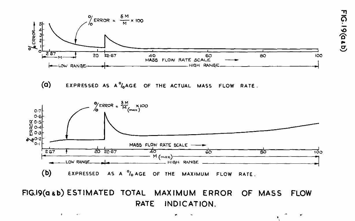
Fiyrc 19~1 shows this e&mated maximum error owr the f'ull mass flow rate scale, as n percentage of the nctwlvdue of mass floi~ rate being indicated. Figure 15b shows the error ;s a percentage of ths maxiimsn mass flow rate.
9 Remnrkn and oonolusions
Performonce well withti the required degree of accuracy is obtainable, as shown in Fig.19.
As the output is a shaft rotation the system could be mdified for remote indication on several diff'errmt dials or scales, each cdibrated for a partlculnr a.i~ duct.
Further refinement of indicntion and accuracy if destied could be met by extenii~~g the zndi-ting scale to three or more sweeps as required.
This technique mzy also be of use for the d-hot indication of fuel to air mass florv ratios.
List of S yiibols
A.,,A2 etc. = Gonstants of lntegretion
A = Bridge Arm RedsLance, proportional to 'P'
B = 1, II I, 11 ,, 'Tf
C c II 11 ,I tt I, Q'
D = 0ynemic lYressure, absolute
E = Applied voltage to motor circuit (without feedback)
Ef = ,I 81 t, I, !I (with feedback)
", $
=Motor Back - LLF.
F = Motor torque
G = Resistance of moving coil relay sensing coil (150 ohms)
H = "Specific" Resistance of 'Ii' Resistance High Range Track (894 ohhad)
i a = idotor &mature Current
if = lioving coil relay feedback coil current
i = IJovmg coil relay sensing coil current
i 0
= Ve.lLle of 4 to maintain a steady state e. position (5 x 10⁴ i;nps)
3 = Value of i to maintain a steady state $1 position
Jm = Effective lbment of Inertia of Servomotor System (800 p cm2)
Jr = Moment of Inertia of moving cdl relay a.rmature (25 gm em2)
- 17 -
.
k,,k2 etc. =
L
Li
n
P
R
Ra 1‘
%
‘%
T
t
At
U
Y
V
w
X
Y
z,,z* etc. =
'i =
80 =
% q
Q zz
List of s- I .fribols (Contd)
constants
Sesistanse xn series ~5th Bridge Network
iiess-flow rate of air
Ratio of feei?back coil turns to sensing coil turns xn mm-ing coil relay
Statx Pressure, absolute
Generalised resistance arm of bridge
ILotor Armature circuit resx3tance (700 ohms)
Ratio of gear-hg, servomotor to in3icatmg spindle (432/l)
Torque Rate of moving coil rela spring (ZOO dyne cm6 per i-e&an T
armature centralising
Torpe Rate of moving coil relay contact leaf spring (6000 dyne ems per radian)
Temprrature, absolute
Tine
Operating delay time of motor control relays
Sum of bridge arm resxstsnces (= h + I3 + C + X)
Air stream velocity
Lpplied voltage across brMge and serxs resistance IL*
iiesistance of balanced bridge ns viewed by sensing ooil,
c =-I
i3rifZge arm resistance gxving "answer" (steady state x+,
Sesistanoe of balanced bridge, as viewed by input points
i (xtc)JAtq _
J
Ooeff%ozents and constants
Input, or clesired sngdl,z position of 'X' rcsistanoe tl-nok wiper
Output, or actual 2nguls.r position of 'X1 resistance track wiper
+* 0 = Any&r limit of relay lnovement at dnrch contact is made ( 20.008 radims)
‘$, = itn@lar limit of relay movement (to.07 radians)
w = Hmimum (or saturated) value of aee/dt
P = Eensity of air
"rl = Phase angle
& = zE%zase angle
No* - Author
1 Rogers 1iurty
2 AndreSS
3 An&rem
4 Sticfies Sizer
5 Uttley HammOlld
Title. etc.
Relay Servomechsnisms. Trans. of the A&IS&, November 1950.
Sensitivity and Output ii'ormula for Resistance Briclgcs. Communications and Electronios of the A.I.E.E., Nay 1950.
Improved So?utions of the Unbalanced Bridge Circuit. Rev. Sci. Inst., February 1953.
EIot Wire Anemometer for Ir;easurenent of Small Air Flows. FL&E Tech Note No. SL 50.
Stabilisation of ON-OW Controlled 3srvomechanisms. Paper in "Automatic and Xsnual Control", XL?.. lkstin.
- 19 -
Analysis cf servo system 1 GenW?al
This analysis seeks to demonstrate the impprovoment effected by using this type of secondary 'knock-off' feedback.
The requirement for this servo system is th&, for any step function change cl a?y of the variables, the ,,ointer shcdd move reasonably quickly to lndicnte the new value without any overshoot. It is assumed in this ardysis that the chsngoovcr time delay of the control relays, being of the order of 2 milliseconil 8, is negligibly mall in comparison with the duration of the other sequences,
The normal method of analys5.n~ on-off servo systems is by phasc- plane represextationl95, i.e. plotting error lee1 usainst error rate ,ae I --% , or, for the moving coil relay, plotting displacement ')I against at
'alJ' at l
As this nny not be familiar to the general reader, and t&z representation and coincidences are not d5.rcctl.y appreciated on suoh diagrems, this method has not been used. Its advantages are particularly apparent whore a dampea oscillatory tmnsicnt of '0,' is permitted. in response to n step change, but in the ease of dead-bent operation a straightforward tti-, analysis is cqudly pffective.
-The functioning of the system is described in paragra@ 5.2 and Figmes 9 and 10, and this analysis is related to the sccpn~es shown in these diagrams. It will be uncful to study first the system behaviour without feedback.
2 Without Feedback
In the motor system, the torque developed is proportional to the mature current, ns the -i;ermnnent magnet flux is constant, Thus:-
P -: k i 1 a . . . (= 2 x IO6 x ia aYn0 -1 . (10)
Also de ae
E g = rk2-$ . . . (= 432 x 0.0875 $ volts) (11)
and
l?rom (121,
?Lrd from (IO), ,
E = EPB aa = Eg + 700 i, .
(E-E) ia = 5
700
(12)
(13)
- 2c -
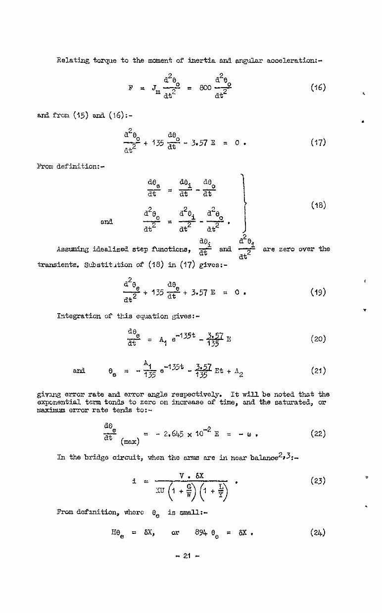
Reld%g torque to the moment of inertia an.3 angular acoeLLeration:-
a2e I=Jmd
a28 at*
= 8000 at2
(W i
and fron. (25) and (IS):- .
a2e ae d+ 1352 at2
- 3.57 E = 0 . (17)
From aef inition: -
de de. de -zsl -0 at at at
a2e (18)
ana a2ei a%
2 =-e-o* at2 at2 at2 1
ae. A and
a2e. Assuming idealised step ticticm, dt I
at2 are zero over the
transients. %bstitdA.on of (18) 3x3 (17) givcs:-
a2a de e+ 1352 at2
+3.57E = 0.
Integration of tLi.s equation gives:-
and h1 ee = -13~~ -'35t-.xiz,,+,
135 2
(19)
(21)
gixulg em-012 rate and error angle respectively. It will be noted that the expmential term tends to zero on increase of time, and the saturated, or maximum error rate tends to:-
de e ati (max) =
- 2.645 x 1o-2 E = -ur
In the bridge circuit, when the arfns are in near ba.lanoe2#3:-
Prom dcfhniti.on, where ee is small:-
Hee = fix, or 894 Be = 6x .
- 21 -
(22)
(23)
(24)
.
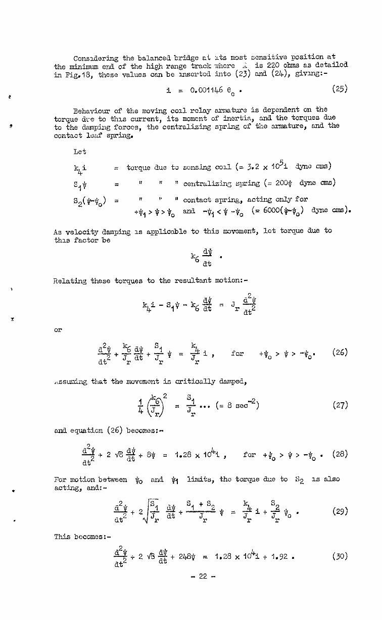
Consxlering the balanced bridge at Its mc& sensitive position at the minimum end. of the high range track -&cre .; is 220 ohms as detailed in Fig.18, these vslues can be mserted into (23) and (24), givme;:-
i = 0.00:146 e, . (25)
Behaviour of the moving cod relay armature is deFerdent on the torque dce to thus current, its moment of inertia, and the torques due to the damping forces, the centralizing spring of the armature, and the contact leaf spring.
Let
k4i = torque due ta sensing cod (= 3.2 x ldi 3pe ems)
As velocity danping 1s applicable to this iwvement, let torque due to this factor be
Relating these torques to the resultant motion:-
k,+i - s,* a26 -kg% s Jr2
or
a2$ k6 a$ so 5t. z+p+q = srL, for Jdo > 6 > -eo. (26)
..ssuwing that the movement is critically damped,
. . . (= 8 d2) (27)
and equation (26) becomes:-
& at2
+ 2 ~73 2 + e* = 1.28 x 10⁴i , for +#o>$>-$ob' (28)
For motion between q. and $1 limits, the torque duo to S2 IS also acting, and:-
&+2s1A!kc at2 /
_- sl + % 3. s2
Jo at Jr $ = Jr = + T if0 ' (29)
This bccomes:-
A&! at2
*2+$248$ = 1.28 x 10⁴i.+ 1.92 . (30)
- 22 -
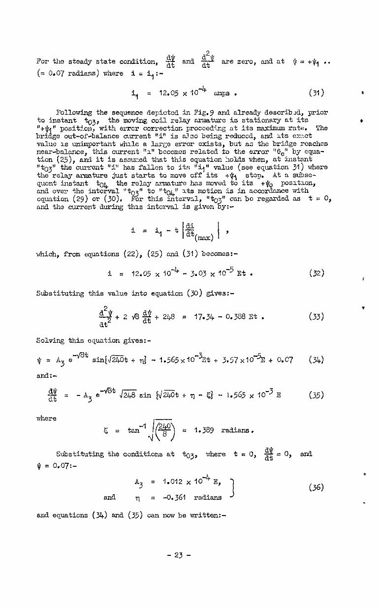
For the steady state condition, a2 ' $ end 2 arezero, an&at (r=t1)1 . . (= 0.07 radians) where i = i,:-
% q 12.05 x lo+ aap3 . (31) *
Following the sequence depicted in Fig.9 and already dcscrib&, prior to instant to3, the moving coil relay -turc is stationary at its . "-t-Q * positLon, with error correction procoedtng at its maxkmsr~ rate. The brl & e out-of-balance ourrent wi" is nloo being reduced, an8. zts exzct value 1s unimportant wtile a 1arGe error exists, b-Jt as the brtige reaches near-balance, this current r'z" becomes related to the error "6," by equa- tion (Q), and it is assmed that this equation holds when, at instant " to3 " the current "i" has fallen to its l'il" valze (see equation 31) where the relay armature just starts to mova off its t$t stop. At a subse- quent ins%nt tO& the relay armature has moved to its tea poslk.on, m-d oven +he interval "tO3" to "tOq (1 its motion Ls in accordance with equation (29) or (30). For this interval, u can be regarded as t = 0, and the current during this interval. is given
i s il - t j%(-) 1 '
which, from quitions (22), (25) and (3-l) becomes:-
i = 12.05 x low4 - 3.03 x 1O-5 Et .
Substituting this value into equation (3) gives:-
2 ti+2&+2@ = 17.34-0.3BEt. at*
Solving this equation gives:-
$=A e -vQt 3 sin[\1240t t qj - 1.5G5%10 -3Et + 3.57x10-E * o.c7
al-d.:- a= at -A5 e-*' J248si.n
where
@i% t q - @ - 1.515 x lO-3 E
s \8 >
= I.389 radians.
c!L- Subotitutlng the conditions at to3, where t = 0, dt - 0, and $ = 0.07:-
A3 = 1.012 x IO -4 E,
and rl = -0.361 radians 3
and equations (34) and (35) can now be written:-
(32)
(33)
(34)
(3.5)
- 23 -
o : E c
q.o-12 x ,f4 e-at sin (&t - 0.361)
- 1.565 x 10⁻³t + 3.57 x If5 3
+ 0.07 (37)
$& = -&0,2x,0-4,[7Q e+ sin (&Ft-1.75) + at I
l.5~5x~O-3 3
(38)
describing the relay motion over the ti~terval to3 to to@ If this kterval is called t3)+, then, at instant "04, $ = tQo = 0.008, and iQ!=s! at at ; end xibstitutxons into equations (37) and (38) give the
( "Q/+1 follok.ng relationships:-
E c
1.012 x low4 e+t34 sin (15.49 tx - 0.361)
- 1.565 x 10 -3 t34 +
3.57 x 10⁻⁵ 3
+ 0.062 = 0 (39)
and
i!k -E c
1.012 x 10⁻⁴ x q5.75 e -@t34 dt(ta) =
x sin (15.49$ -3 - 1.75) + 1.555 x IO I
. (40)
Instant t fi!t
can now be regarded es the begwing of a new transient period d&.ng w ch the motor slows down to a standstill. For this period t=o at t equation (32 Y
mfi if i( O&) 1s the value of i at this instant, f?om
i(o4) = 12.05 x 10 -4 - 3.03 x IO -5 E t
34
and from equation (25),
For this perid E is now zero and the motor is short-drauited. The descriptive equation for the error, from (19) now becomes:-
a2e 2
de
at2 + 132 at re = 0. (43)
Integration gives:-
and
de e = A, e-'355t at Ii .
8, = -he -135t + iI
2'
(44)
(45)
- 24 -
de Inserting the lmom condaltiona at to4 where t = 0; -$ = -2.645~10%;
rind e, = 8, :- (04)
A, = - 2.65.5 x IO-’ E (46) ’
A2 = Be (04)
- I.96 x Id+ E (47) *
and equations (I+&) and (45) can be written
a0 -2 = - 2.645 x ,0-Q E .--t at (48)
0 e = e YO4)
- I.96 x 16~ E (I - e-'35t) . (49)
The current transient over this period, from equations (25), (&I), (42) and (49) is:-
i = o.o011t+6 8, = 12.05 x I&
- c
3-03tjq + 2.245 (I - e-'35C)10-2
3 1o-5E .
(50) ' It will be noted from equations (49) snd (50) that the final stcady-
state values of 0, and i arc given by:- , t
ee(s) = '0 (04)
- 3.36 x IO+E (51)
i(s) = ?2.05 x IO+ - c
j.ojt + 2.245 x IO -2
34 3
10-5 Is l (52)
The motioion of the relay armature 1s given by equation (28), as the centralizin~ sgcing only is acting, from (50):-
and by inserting the current trarxient
& at2
4 2 93 $$ + S$ = Z, e-135t + z2 (53)
where =I = 0.2875 ~10'~E
and z2 = 15.42 - (0.388tj4 + 0.2875 x IO-') E .
Solution of this equation gives:-
$ = (A5t + A6] edt + "',~~~$"+ 3
(54)
(55) F
s (56)
ana:-
- 25 ”
.
$ = C A5 (1 - 6%) - & A
135 z1 e-‘3fjt 17569 l
(57)
Inserting confiitions at to)+ where 1;1 = O.COS; t = 0; and g =
s.!i dt(tGj; then:-
z1 zk “6 = o.oos-*- a
ma A5 a$ t V'B A6 .t
135 z, = yt,) 47569 ’
The final steady state value to which. jr from equation (56):-
n
&12 e(s) = 8 = 1.9275 - s&O@5 $+ t 0.359375 x IO-'] E. (60)
(59)
tan&, as t -a O(L , is obtained
Referring back to equation (52), it is evident dition for the requirement of no overshoe-c is tha limit of this condition is itsi = 4, = -5 x lO-2. value into equation (52) gives he rclationship:-
121 E =
3.03 t34 + 2.245 x 10 -2
that a necessary oon- i(&s~r;& tz the
. (61)
EquaLlow (61) and (39) are both relationships between G and tJ&, and by substitution the value of' t34 1s contained in the rcl.ationshxp:-
as the motion of the armature from instant tO4 on-wards. (57) b
Also, equation ecome5:-
+
a= at - [0.0181 t 0.0765j ewat - 0.000261 e-‘35t . (71)
From inspection, g& . dt 1s always negative, aniL tends to zero as
t+m. Therefore, there is no instant like t; z!!t
&rix a lymin) value where dt is zero. Therefore in this case the chsracteristio of $ I"cllows the dotted line shcvm in Fig.9, ed approaches the -$. line asymptotically from nbcve.
Thus the value of ?3 = 11.825 volts gives the optimum condition of operation without overshoot of indication, end from equation (22), the maximum error correction rate is
1~1 = 0.314 radians/set. (72)
3 rlith Feedback
Figal illustrates the transient behaviour of the system under the I)
same conditions 33 Fw.9, except that feedback effects are now mcluded, ard prior to instant tO6 it is assumed an error has been establishetl large enough for the error correction rate to saturate to its maxinwn . value. Pig.lOa show the sensing coil current, which, if regarded as near-balance, is also proportional to the error "Be" (see equatban 25). The moving coil relay armature 1s now actuatedby two current torques, one due to the current "i" in the sensing coil, and the other u opposi- tion clue to a current "if" in the feedback coil which is shown in Fi~.lOb. The cl'fectivc current shown in Fig.100 can be taken as (i - EQ) where "n" is the ratio of turns of the feedback coil to the sensing coil.
Atinstant t6 9
the rate of error correction is given by equation (23), anti from (25 :-
di de x5 = 0,0011l+6 2 (73)
ai
dt(uax) = - O.OOll&f5 w = - 3.03 x 10m5 Cf mps/sec , (74)
The ef uctive current "i -2
- ni I' 12.05 x lo (see equation 31 P
has just reached the value t-5.9 = amps, and ths moving coil relay armature
starts to move from its "t$j" possticn in sccordanoe with equation (29), tlm effective current navbeing use& Thus:-
s2 $0 i - nif) ty (75) I-
describes the motion over range +$, > 9 > +jro. This becomes:-
- 27 -
The effective currer,L transient over the period tc6 to to: (called t57) is:-
(i - n+) = i,-t i I "g ""(max) '
(i - nif) = 12.05 x 10"~ - 3.03 x m-5 i?*t , (77)
SubstitL~tionback into (76) &es:-
i$ i'l.012 x 10 -4 9 -.k3t67
Sin("5.4997 - 0.361) L
- q.565 x 10-3t5, + 3.57 x IO -5
3 + 0.062 = 0 (78)
aEd:-
9 -4 -G3t57
“~w =
- E, r1*0,2 x 10 Lc
x 95.75 c sln(15.49t67-1.75)
t 1.565 x IO-~ L (79) J
mitt! feea?Jack, the xr7omotor 32 required to openate at it3 maxim~rn ratiq, and it, 1s coflvcnient here to insert the rated value of:-
E f = 24 Volt", 1
Inserting this value into eyxations (78) and (79) giws:-
(80)
and
tG7 = 3.67 seoonas
- 28 -
ci - %fo7) = 12.05 x IO -4 - 3.03 x 10⁻⁵ Tf tG7 (83)
sad after the step change:-
?07) = 12.05 x IO -4 - 3.03 x 10⁻⁵ E* t(-- + nif . (84) i
This is clearly dependent on the value of' n$, and for purposes of . this argment is assumed to be a.djusted to:-
nif = -k i, - 112.05 x 10 -4 - 3.03 x 1o-5 Ef t($ (85)
icoll = + i, = 5 x 10m6 SUPS
immdiatcly after thz step chang-.
From equation (25):-
8 = -p.&; = 4.37 x C-3 radians . e(07) l
(87)
By similar steps to tnose used i;l deriving equations (43) to (49), the error transient id given by:-
6 8 = 0 e(07)
- 1.96 x I,-~,~ (1 - e-135t) (88) i
and ths current transient by:- ?
i = o.Om146 e = 5x10 4
0 - 2.245 x 10 -7 Ef (1 - e-y (89)
foilowing the &d&d. curve of Fig.10~ from instant tc7 onvfd.s. The steady stats of "x" us t + 83 is:-
5s) = 5x10 -6 - 2.245 x lO-7 EC = -6 - 0.335 x IO amps l (90)
fhe movement of the relay arw.ture from instant to7 onwards is given by equation (28), (89); thus:-
using the current relationdip svenby equation
& + 2 k$i, 814 = .i,28.104 c 5x10 -6 Lit2 - 2.245~1O"~E~ (I - e-jt) 3
i&t at2
+ 2 48 $ + 8$ = 0.069 e-'35t - 0.005. (91) :
Solution of this equation gives:-
- 29 -
and:-
t
22 at = ifi (1 - &t) - -I'8 A& e-*t
;rhere '8
= 0.0086
and A7
= -%0127
from imtial. condition:: at ta7 where p = r.llJrr9 d’( - .
Ut(to7) = -0.0375 (me eqmtion 82).
-1.35 x 0.069 e -?35t
17569 (Y3)
(94)
(lo = 0.008, t = 0, and
- 0.0005 e-‘35t . (95)
The second term 1s negli.gibly mall ezd from ms,peotion, the ,Q' czLrve 3tarts at tic;7 (where t = 0) with a negative slope, the mmcrloal vdde of which progressively decreases, until at the value:-
b+gjL 1‘03 ?L!COlX!S (96) *
the 31056 is zero. After this xnstant, the slope becomes positive and as t + co, a! -, *
at * 'Ihe "I)" curve thus follows the dotted line shorn on Pig. IOd, and liis a v"( Lti) value at t = 1.03 seconds. Insert- thx value mto equatLon (92) ;,ives Lhe mmerical result: -
"(&) = -%000?a+6 raaians . (97)
This vaiue does not reac;h the therefore there is no re-corro~-"
-(r. lmit of -0.008 radians, -u,ve action from the relay and thus no
overshoot of mdication. deferrug to equation (74) the saturated error correctron rate 1s now given by:-
(J = 3.0: x 10-5 x 24:
O.o011;6 = 0.634 rads,'neo (98)
a2d It 1s ev-dont +&at, m this pai- tG* case, the sc twatw5t e:cror correstlon rate mild be still further lncreaocd jby ucrease of Cf) until $cnin) = -0.008.
ch2s the cordp..mt~ve result3 of this servo system, for a requirement of no overs!~oot of mdioation are:-
~i~shout feedi~ack, I.~mcm~id error correction rate = 0.3'14 rod.s/sec. With fec~ac!:, / ,I II !I > 0.634 r&/sec.
It mllbe noted that, in tne actual instrmmnt the I,- error ~omccnon rate has bcez adJusted to a slqhtly lower flgure of 33.3'/sec or 0.581 rack/set by loim+n&, the mtor uo1ts.g~ Ef to 22 volts. ThlS
rate has been fmnd adeqtiate in ~graotxce, and saves 3ome of the -"iear anil tear of the servo system and relay contacts. It IS pointed out thai this l'eodb~ck adjmtic& (~LVLT~ the above onalysc~ coditions) is sSted for
- 30 -
the position of uzzcimm bridge sensitivity, and at otiier balanced posztiom, &i z being less, there my be several steps of feedback operation before final balance a-d these (occ~ very rapidJy) mvolve s-al. quick change-over sequences from the relays, as show JJI the resow in Fig.lB.
- 31 -
Yt.2079.CP.230.f3 - Prknted in Great Brrtain.
FIG. I
DYNAMIC PRESSURE TRANSDUCER K /x MASS FLOW
- ,,,? ,,y = B II
--ii- SiAilC -----*
PRE5S”RE
-----*
AIR DUCT ---s-v
FIG.l. DIAGRAM OF METER
.
DYNMIIC PRESSURE TEST PRESSURE TRANSDUCER GAUGES
,iCATlNG ON - 20% RANG
POINTER FOR INDICATING ON
2oyo _ ,QQ% RANGE
Fir&x ON MIDDLE SCALE
2’ DIVISIONS ON INNER
SCALE
FIG.2. FRONT VIEW OF INSTRUMENT
PRESSURE r~NSDU~ER
TRACK 2.5% - 20%
SERVO MOTOR
20% - 100% RANGE
FiG.3. SIDE VIEW (LEFT HAND) OF INSTRUMENT
CONTROL RELAYS
PRESSURE-TIGHT
VIBRATION MOTOR
AND ECCENTRIC MASS ASSEMBLY
ROLLER GUIDE
CONNEXION HERMETIC SEALS
FIGS, STATIC PRESSURE TRANSDUCER
ELECTRICAL CONNEXION
FIG.6.
SERVO MOTOR
DIAL FACE
“X” RESISTANCE TRACK
2.5% _ 20% RANGE
9: 1 SPUR GEAR
FlG.7. DIAL PLATE, SERVO MOTORS AND DRIVES ASSEMBLY
FIG.8.
co, L
/~I.._.1 eR: ENERGISED POSITION OF CONTACT
de ’ DE-ENERGISED POSLTION OF CONTACTS
N92 TRANSFER
,000 F Y
VIBRATOR
MOTOR
TRANFORMER VOLT, Iph
so-
INPUT
FIG.8. WIRING DIAGRAM
FIG.9.
-TIME
e\. &
I I j /
, I / I
I _--------
.- ,y
/
i
I +c,
0
I I
G COIL RELAY
I to1 eoe t!O3 ta& tlos
-TIME
FIG.9. TRANSIENT BEHAVIOUR OF SERVO SYSTEM (WITHOUT SECONDARY FEEDBACK.)
:
,-
-TIME \ FIG.0
(A) SENSING COIL CURRENT (ALSO PROPORT IONAL TO ERROR
4T NEAR BALANCE )
I l?
1 ; ; I , I
4 1 (B) FEEDBACK COIL CURRENT
(SHEW ti NEGATIVE )
(C) EFFECTIVE COIL CURRENT
-5-___-___ L(S) , ,
G COIL RELAY ARMATURE
( E) ERROR RATE ( E) ERROR RATE
-TIME -TIME to6 to7 toa to3
FIG.10. TRANSIENT BEHAVIOUR OF SERVO SYSTEM (WITH SECONDARY FEEDBACK.)
FIG. I I.
-TIME
-
%- n
do- /I
\ I\ I
I I
\ -% /,/w w I
w I X
(B) MOW& COIL RELAY ARMATURE. :
-TIME
FIG.1 I. OSCILLATORY BEHAVIOUR OF RELAY DUE TO EXCESSIVE SECONDARY FEEDBACK.