Developing Fluid Wall Using the Microsoft Kinect This chapter will walk you through the development of Fluid Wall, a program that integrates the depth-sensing capabilities of the Microsoft Kinect Sensor with the optical flow provided by OpenCV. The program combines the functions provided by OpenNI, OpenCV, and OpenGL to create a fun, real-time, fluid simulation that users can interact with using gestures and movements. In this chapter, we cover: • An introduction to Fluid Wall application • Kinect sensor specifications and how it works • Setting up OpenNI libraries and retrieving Kinect data with OpenNI • A brief look at fluid dynamics and implementing the fluid simulation • Optical flow basics and optical flow algorithms in OpenCV integrating Kinect data, fluid simulation, and optical flow • Current limitations and future improvements for the Fluid Wall application
Transcript
Developing Fluid Wall Using the Microsoft Kinect
This chapter will walk you through the development of Fluid Wall, a program that integrates the depth-sensing capabilities of the Microsoft Kinect Sensor with the optical flow provided by OpenCV. The program combines the functions provided by OpenNI, OpenCV, and OpenGL to create a fun, real-time, fluid simulation that users can interact with using gestures and movements. In this chapter, we cover:
• An introduction to Fluid Wall application• Kinect sensor specifications and how it works• Setting up OpenNI libraries and retrieving Kinect data with OpenNI• A brief look at fluid dynamics and implementing the fluid simulation• Optical flow basics and optical flow algorithms in OpenCV integrating
Kinect data, fluid simulation, and optical flow• Current limitations and future improvements for the Fluid Wall application
Developing Fluid Wall Using the Microsoft Kinect
[ 2 ]
What is Fluid WallFluid Wall is a real-time, artistic, interactive application that captures and displays users in front of the Kinect sensor in the form of silhouettes in a fluid simulation on the screen. It was intended to create an intuitive environment for play and discovery that fuses sensations of light, reflection, and fluids. The application recognizes and separates the users in front of the sensor using the depth information from the Kinect sensor. When the application is started, each new user (any person in front of the Kinect) is detected and displayed on the screen as a silhouette in the middle of a flowing liquid environment. The user can then interact with this environment using gestures and movements that will be tracked by the Kinect sensor. The fluid environment is simulated by a fluid solver in the program, which creates several virtual emitters around each user that control the emission and flow of the fluid on the screen. Each time a new user is detected by the Kinect, the fluid solver assigns a new set of emitters for the new user. They create colored emissions around the user, which flow onscreen with the movements of the user. The emissions can bounce off and be pushed around by different users' silhouettes creating the look of liquid colors flowing on screen.
The program has four modes, each of which remains on the screen for around twenty seconds before switching to the next.
Single color modeA single colored-fluid environment is displayed on the screen with a bluish fluid on a dark background. All users appear as dark silhouettes that interact with the flowing liquid effects. The following image shows people interacting with this mode:
Chapter 9
[ 3 ]
Multicolor / multiuser modeThe program tracks individual users displaying each of their silhouettes with a different hue on a dark background. The fluid emissions from each user are also of the same color as their silhouette, as shown in the following image:
White background multiuser modeThis is similar to the previous mode, but with a snowy white background. Users are displayed as dark silhouettes, with each user being assigned a different-colored fluid emission:
Developing Fluid Wall Using the Microsoft Kinect
[ 4 ]
Velocity vector modeThe fluid environment is replaced with the velocity vector field of the fluid. This vector field is explained much more in detail in the Fluid simulation section of this chapter. For now, the readers can see what this mode looks like in the following figure:
The program captures the velocity of movement and the distance of each user from the sensor. The fluid emitters for each user utilize this data from the user to define the direction, speed, and strength of emissions. This way, the users can interact with the fluid, moving it around with their silhouettes and creating abstract formations from the combination of the colors of the wispy fluid and the several silhouettes being projected on the screen.
The development of the Fluid Wall project involved three different stages of implementation. This chapter will attempt to briefly explain the programming of each of the three stages:
1. Initializing depth and user-tracking objects through input from the Kinect sensor.
2. Setting up an interactive fluid simulation.3. Implementing optical flow to capture users' movement velocities.
The C++ source and header files (included in the media accompanying in this book), which contain all the code needed to compile and run this application in a development environment, include the following files:
In addition to OpenCV, setting up the Fluid Wall for development requires the OpenNITM, and OpenGL Utility Toolkit libraries. Following are the links to download the OpenNI modules (OpenNI binaries and PrimeSenseTM middleware and hardware binaries needed to run the Kinect sensor on a computer), as well as the link to the latest OpenGL GLUT (OpenGL Utility Toolkit) libraries:
As expected, the user will have to set the paths to the required libraries and include files and executables for both OpenNI and OpenGL libraries as well. This will vary depending on the operating system and programming environment, so users should refer to the documentation for each library.
Kinect sensorThe Kinect sensor is a depth-sensing device developed especially for use with the Microsoft Xbox console for gesture-based interaction. It can also be used for applications on the computer using the Kinect drivers and SDKs provided by Microsoft or by OpenNI.
Developing Fluid Wall Using the Microsoft Kinect
[ 6 ]
As shown in the previous image, this device comprises of an IR (infrared) emitter and sensor. This emitter projects an IR grid pattern in front of the device. The rays from this pattern strike whatever objects are in front of the Kinect device and reflect back to be detected by the device's IR sensor. The time taken by each ray to return after it has been emitted is then used by the device to gauge the depth of objects in front of it. The depth map created by this IR pattern is accurate to within a centimeter for objects within a range of 1 to 6 meters away from the Kinect sensor. This depth map is updated at a rate of up to 30 frames per second. Since the data for Kinect's depth stream depends on the reflection of IR rays on a grid of a limited size, the output of the depth stream is a little sparse and, therefore, noisy. The Kinect sensor also comprises of an RGB camera which gives a color-image stream (like a typical VGA camera). The Kinect sensor processes data from the depth and color streams to detect a human figure in front of it. This way it can identify and track up to 6 people simultaneously. The vertical and horizontal field of view of the device are defined as 43 degrees vertically by 57 degrees horizontally. So any person within this range of the Kinect sensor will be visible to it and can be tracked. More hardware specifications and additional information on the Kinect capabilities can be found at the MSDN (Microsoft Developer Network) page for Kinect specifications:
For this application, we will utilize the depth map and the user-tracking information provided by the Kinect sensor.
Setting up the Kinect sensor to retrieve depth and user-tracking dataFor interfacing with the Kinect sensor, this program uses an open SDK, OpenNI, which was released soon after the release of the Kinect sensor for Xbox 360. The OpenNI framework uses the OpenNI NUI (Natural User Interaction) API together with a Kinect driver and NiTE middleware, both provided by PrimeSenseTM. OpenNI is a set of open source APIs for devices and applications using NUI methods (such as gestures and speech) for human-computer interaction.
As mentioned earlier, once set up, the Kinect sensor returns two streams of data; the depth map giving a pixel-to-depth mapping for all objects in front of the Kinect sensor and the video stream data returned by Kinect's VGA camera. As mentioned earlier, we will be utilizing the depth map and user-detection data for this program. Even though the Kinect sensor uses both the depth and color streams to identify and segment a user in front of it, we do not need to access the color stream ourselves. We can simply access the depth map and a similar user map for each frame of the data stream.
Chapter 9
[ 7 ]
The details about the routines involved for this process are further explained along with the code in the source and headers files for the KinectController class mentioned in the following code:
The previous code is included in the KinectController.h file; the OpenNI API headers for accessing sensor data and user-detection routines, and C++ wrappers for OpenNI are also included here. The #define directives in this file will be used in the OpenNI routines for setting the image parameters for the image streams from the Kinect. Even though we will not be accessing the RGB stream (through the VGA camera) directly, the XN_VGA_RES directives are still used to define the overall resolution for the output of the system. The CHECK_RC macro is used to run a quick check on values returned by OpenNI functions.
All routines required for setting up access to the Kinect sensor and managing its data are defined in the KinectController class shown in the following code segment:
/*@ file: KinectController.h */
/** (Default) Constructor with initialization list.* @param _maxDepth initialize depth threshold for* Kinect depth data stream (less than 6000)* @param _maxUsers initialize maximum users to be* detected (between 1-6)* @param _depthMatrix initialize an empty cvMatrix to* store the Kinect depth-map
Developing Fluid Wall Using the Microsoft Kinect
[ 8 ]
* @param _usersMatrix initialize an empty cvMatrix to* store the Kinect userID-map*/
/*! Constructor with initialization lists*/KinectController () :_maxDepth( MAX_DEPTH ),_maxUsers( MAX_USERS ),_depthMatrix( Mat::zeros(480,640,CV_8UC1) ),_usersMatrix( Mat::zeros(480,640,CV_8UC1) ){ init();} /*! Destructor*/ ~KinectController() { kinectCleanupExit();} /*! Initialize all KinectController variables & modules*/ XnStatus init(); /*! Depth & User Tracking Modules*/ XnStatus update(); /*! Update the XnOpenNI Depth & User tracking data for each * frame of video captured */ XnStatus reset(); /*! Set Depth Threshold */ void setDepth(int depthDelta); /*! Get depth matrix for current video frame */ void getDepthMat(Mat &depth){ _depthMatrix.copyTo(depth); } /*! Get matrix of tracked users for current video frame */ void getUsersMat(Mat &users){ _usersMatrix.copyTo(users); } /*! Get maximum number of users to be tracked */ int getMaxUsers(){ return _maxUsers;
}
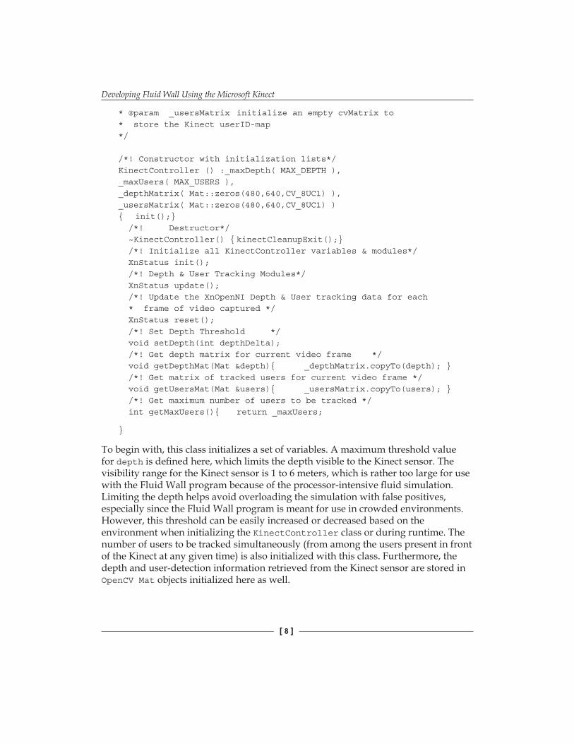
To begin with, this class initializes a set of variables. A maximum threshold value for depth is defined here, which limits the depth visible to the Kinect sensor. The visibility range for the Kinect sensor is 1 to 6 meters, which is rather too large for use with the Fluid Wall program because of the processor-intensive fluid simulation. Limiting the depth helps avoid overloading the simulation with false positives, especially since the Fluid Wall program is meant for use in crowded environments. However, this threshold can be easily increased or decreased based on the environment when initializing the KinectController class or during runtime. The number of users to be tracked simultaneously (from among the users present in front of the Kinect at any given time) is also initialized with this class. Furthermore, the depth and user-detection information retrieved from the Kinect sensor are stored in OpenCV Mat objects initialized here as well.
Chapter 9
[ 9 ]
The depth map retrieved here, at a resolution of 640 x 480, can be pictured as a typical two-dimensional array of pixels where each element of the array contains the distance, in millimeters, from the depth-sensor plane to the nearest object in front of the sensor. So, for each RGB pixel in the RGB stream, the depth map defines a corresponding depth value for that pixel. The user-detection information is accessible in a similar format of a 640 x 480 pixel user-ID map where each element is either blank or contains the used ID of a detected user (provided by the API). This way, the user-tracking information can simply be used as a kind of mask on top of the depth map to track the depths of individual users easily. The following code gives a look at some forward declarations of a couple of OpenNI callbacks defined later in the code and the init() function for the KinectController class:
// XnOpenNI Callbacks when user is detected or lostvoid XN_CALLBACK_TYPE User_NewUser_Cback (xn::UserGenerator& generator, XnUserID nId, void* pCookie);void XN_CALLBACK_TYPE User_LostUser_Cback (xn::UserGenerator& generator, XnUserID nId, void* pCookie);
// Initialize all KinectController variables & modulesXnStatus KinectController::init(){// Initializing maximum iterations of Kinect data stream// capture before resetting them (this is useful when // running the application in crowded environments so that// the Kinect can purge tracking information of previous// users and quickly continue tracking the most recent// players)_maxIterate = ITERATIONS_BEFORE_RESET;_iterationCount = 0;
// Initialize Status variable and creating Context object initDepthControl(); CHECK_RC(xnRetVal, "InitDepthControl"); return xnRetVal;}
Developing Fluid Wall Using the Microsoft Kinect
[ 10 ]
As shown in the following code, the initDepthControl() routine starts by setting the status of the Kinect as OK and creating a special xnContext object which identifies the Kinect device. All nodes related to Kinect functionality are created through this context object. Next, the initDepthControl() method creates the depth-generating and user-generating nodes. These two nodes are used in defining the depth and number of users in front of the sensor at each frame. The initDepthControl() method also creates special variables that set the callback values for whenever a new user is identified in front of the sensor or when an existing user (previously identified) is lost by the sensor (exits the sensor's viewing range and does not return within the next few seconds). It then runs the command to start generating the two nodes. Some more details are mentioned as comments in the following code:
/* @file KinectController.cpp */
XnStatus KinectController::initDepthControl(){// Initialize Status variable and creating Context object xnRetVal = XN_STATUS_OK; xnRetVal = xnContext.Init(); CHECK_RC(xnRetVal, "Context.Init");
// Generate all objects xnRetVal = xnContext.StartGeneratingAll(); CHECK_RC(xnRetVal, "StartGenerating");
return xnRetVal;}
The update() function runs at every iteration of the timer, updating all the Kinect variables initialized in the init() function earlier. This populates the depth and user data matrices, (_depthMatrix and _usersMatrix) and runs some image-processing functions to prepare these matrices for use in the fluid, defining the optical flow and the fluid simulation. There is also a reset function defined within the KinectController class, which is called every time the system has been running for a few thousand iterations (defined by a threshold value) so that all the Kinect functions can be reset. This is due to the fact that this application has (usually) been used in environments (such as exhibitions) with a lot of people constantly appearing into and disappearing from the Kinect's field of view. This can overwhelm the system since it can track only up to six users at a time. If all six user IDs are already in use, it's helpful to purge this data every little while. So the reset() function makes sure the system variables are reset after some time interval so that the sensor regularly recaptures and populates the most recent users to keep it mostly up-to-date. This process is virtually undetectable in the simulation and helps to keep the visualization active. The code for the update() function described here is presented as follows:
/* @file KinectController.cpp (continued) */
/** Update the XnOpenNI Depth & User tracking data for each * frame of video captured */XnStatus KinectController::update(){// Restart all Kinect processes every once in a whileif (iterations > maxIterate) reset();
// Context: Wait for new data to be availablexnRetVal = xnContext.WaitOneUpdateAll(xnDepthGenerator);CHECK_RC(xnRetVal, "UpdateAll");
// DepthGenerator: Take current depth mapconst XnDepthPixel* pDepthMap = xnDepthGenerator.GetDepthMap();const XnDepthPixel* pDepth = xnDepthMD.Data();
Developing Fluid Wall Using the Microsoft Kinect
[ 12 ]
const XnLabel* pLabels =
// UserGenerator: Define number of users to be trackedXnUserID* userID = new XnUserID [maxUsers];XnUInt16 nUsers = maxUsers;
// UserGenerator: Get Tracked Users' IDsxnUserGenerator.GetUsers(userID, nUsers);CHECK_RC(xnRetVal, "UserGenerator.GetUser");
// Create temp mats to store depth & user detection values// before flipMat toflip_depthMatrix = Mat::zeros(480,640,CV_8UC1);Mat toflip_usersMatrix = Mat::zeros(480,640,CV_8UC1);
// Iterate through current frame and store depth & user// detection data in matricesfor (int ind = 0; ind < HEIGHT * WIDTH; ind++){// check if current pixel is within depth threshold if (pDepthMap[ind] < _maxDepth) { toflip_depthMatrix.data[ind] = pDepthMap[ind]; toflip_usersMatrix.data[ind] = pLabels[ind]; } } flip( toflip_depthMatrix, depthMatrix, -1 ); flip( toflip_usersMatrix, usersMatrix, -1 ); _iterationCount++; return xnRetVal;}
It is interesting to note here that the depth and user data being retrieved from the Kinect sensor is also flipped in this update() function using OpenCV's simple flip routine, described as: void flip(const Mat& src, Mat& dst, int flipCode). The first two parameters here are clearly the source and destination, but the last, flipCode, defines the axis of flip. Here 0 means flipping about the x axis, a positive number means flipping about the y axis, and a negative number means flipping both axes. The reason for a horizontal flip is so that when the data is displayed on screen, it is mirrored and users are better able to relate to it. The y axis flip has to do with the OpenGL display being used for visualization.
Chapter 9
[ 13 ]
For most image streams, such as ones from the Kinect sensor, the origin is assumed to be the top-left corner, but for OpenGL displays, the origin is the bottom left. So, the vertical flip used above is in order to compensate for this. Additional functions dealing the setup, display, user-detection, and sensor shutdown for the Kinect are explained along with the following code:
/* @file KinectController.cpp (continued) */
/*! Shutdown and restart all Kinect modules */XnStatus KinectController::reset(){ kinectCleanupExit(); _iterationCount = 0; init (); update (); return xnRetVal;}
/*! Shutdown function */void KinectController:: kinectCleanupExit(){ stopDepthControl();}
/** [Callback for when New User Detected]: This code is * executed every time a new user is detected by * UserGenerator node * @param generator UserGenerator node * @param nId ID of user detected (range: 1 to Maximum * users allowed) * @param pCookie any object can be passed through the * register functions (such as * RegisterUserCallbacks() function) using * this *pCookie */void XN_CALLBACK_TYPE User_NewUser_Cback(xn::UserGenerator& generator, XnUserID nId, void* pCookie)
Developing Fluid Wall Using the Microsoft Kinect
[ 14 ]
{cout << "New User: " << nId << endl; }
/** [Callback for when User Lost]: This code executed every * time an existing user is no longer visible to * UserGenerator node for more than 10secs * @param generator UserGenerator node * @param nId ID of user (range: 1 to Maximum users * allowed) * @param pCookie any object can be passed through the * register functions (such as * RegisterUserCallbacks() function) using * this *pCookie */void XN_CALLBACK_TYPE User_LostUser_Cback(xn::UserGenerator& generator, XnUserID nId, void* pCookie){ cout << "Lost user: " << nId << endl;}
Even though the Fluid Wall application uses OpenNI API directly to access the Kinect data, it is important to mention here about a few recent additions to OpenCV's API that allows access to Kinect data as well. OpenCV's latest API (OpenCV Version 2.4.2) now provides its own OpenNI wrapper for accessing depth and RGB streams from the Kinect sensor. This is quite a useful addition especially since the OpenCV constructs allow for a much simpler syntax for accessing the OpenNI modules and can be used without having to include additional libraries and callbacks within the code.
Here's a simple program to capture Kinect's depth stream with OpenCV:
To use these OpenCV's OpenNI API functions, the OpenCV source has to be downloaded and recompiled using OpenNI and PrimeSense modules. OpenCV's documentation explains the installation and usage of Kinect and other OpenNI-compatible depth sensors much more in detail in their online references. This includes an explanation of how to configure and rebuild the OpenCV binaries with support for OpenNI for all three platforms, namely Windows, Linux, and Mac OS X. The readers can find the documentation here:
While it was imperative to add a reasonable mention of OpenCV's most recent developments in this direction, however, OpenCV's OpenNI functions have not been used in the Fluid Wall source at this time. This is due to the fact that despite the easy access to depth, and RGB streams provided by the OpenCV wrapper, it does not yet cover the user-detection, user-tracking, or skeletal-tracking modules. While identifying and tracking the users' motion is a central element of Fluid Wall's interactive programming, however, given OpenCV's rapid development in this area, we may yet be able to make a complete transition to OpenCV-only constructs for this program in the very near future.
Developing Fluid Wall Using the Microsoft Kinect
[ 16 ]
Fluid simulationThe fluid simulation implemented in this project is based on the implementation of fluid dynamics for game engines developed by Jos Stam, senior research scientist at Autodesk Research (]Real-Time Fluid Dynamics for Games, Jos Stam, Conference Proceedings: Game Developers Conference).
Fluid dynamics define the natural flow of gases or liquids in different mediums. They are based on the use of precise mathematical models that depict the physics of fluid motion, such as those described by Euler's fluid dynamics equations, the Oseen equations, or the Navier-Stokes equations. However, to use these models in a real-time, interactive application, the fluid system needs a very fast and reliable solver to compute (or solve) these computationally intensive equations in real time. The solvers developed by Jos Stam, based on the Navier-Stokes equations, make it possible to run these complex equations in real time by taking away from the strict physical accuracy of the model and focusing instead on the visual quality of the output.
The model defines the state of a fluid at each time instance in the form of a velocity vector field, that is by assigning a velocity vector to every point in space at a given instant of time. Using the current state of velocity and the current set of forces acting on a fluid body, the Navier-Stokes equations dictate evolution of its velocity field over time. The compact vector notation for this equation is given as the first equation in the following figure. Here, terms on the left-hand side of the equation denote the overall acceleration of the vector field, with u being the flow velocity. On the right-hand side, P denotes pressure, μ being the kinematic viscosity, and f being other body forces (typically only gravity). These terms combine to define the change in velocity for the vector field:
This velocity vector field can be modeled as the flow of air in an enclosed room. However, by itself, this field is not of much interest until it starts moving other objects such as dust or smoke along with it. The movement of these particles can be deduced from the velocities surrounding them, that is, from motion of the velocity vector field around them. The fluid dynamics described by Jos Stam don't however model these particles individually. Instead, the field of smoke or dust is modeled in the form of a continuous density function. The equation to represent this field is very similar to the one representing a vector field, as shown by the second equation in the previous figure. In this equation, ρ is the fluid density while v and S denote the different viscosity and different forces (in addition to f) applied on the density field.
Chapter 9
[ 17 ]
Finally, since this model as-is still isn't applicable in practice (as the fluid theoretically covers an indefinite amount of space), it is important to create a finite representation of the fluid. So, as proposed in Stam's algorithm, the two-dimensional space used in the visualization is divided up into a finite number of identical cells equally spaced apart. The fluid flow is then modeled from the center of each of these cells. In Fluid Wall's simulation, even though the depth-image data is retrieved at a resolution of 640 x 480 pixels, this grid of cells has been restricted to a fairly small size (128 x 128 pixels) to keep the solver computations minimal in order to make sure the program can still run in real time. The following screenshot shows a layout of the grid and vector field generated by Jos Stam's original algorithm:
In terms of visualization, when a person steps in front of the Kinect sensor, a mirrored silhouette of the person is displayed on the screen. The program then starts emitting the fluid around the person's silhouette on the screen. If a user is being tracked, the fluid emissions are generated from a number of fluid emitters assigned to different sections (top, midsection, and base) of this silhouette. These emissions created are the density fields flowing through the velocity vector field mentioned above. The direction and flow velocity for the density fields are dictated by the movement of the user in front of the Kinect sensor. This information is computed using OpenCV's optical flow method explained in more detail in the Optical flow section in this chapter.
Developing Fluid Wall Using the Microsoft Kinect
[ 18 ]
The following screenshot shows the vector field generated around the silhouette of a hand by the emitters in Fluid Wall:
The FluidSolver class (FluidSolver.h and FluidSolver.cpp) implements the solver routines explained here to construct a unified density field and fluid model for movement velocities of all objects moving in front of the Kinect sensor (without tracking separate users). The FluidSolverMultiUser class (FluidSolverMultiUser.h, FluidSolverMultiUser.cpp) extends the solver's functionality to provide separate emissions for each of the individual users being tracked by the Kinect sensor.
This chapter will not cover the programming involved in implementing the fluid solver itself, since it is an independent module not employing any OpenCV functionality. The details about each of the solver classes and their respective functions can be found within the code included with this chapter. Additionally, the original paper by Jos Stam gives a much more detailed explanation of the fluid solver's implementation and a more in-depth view of the underlying algorithm. Further clarification and a closer look at the derivation of the fluid solvers through the Navier-Stokes equations can be found in Jos Stam's paper available online at the following link:
The page also provides a link to Stam's own simple prototype implementation of this solver programmed in the C programming language.
Chapter 9
[ 19 ]
Rendering the simulationBased on Stam's original demo mentioned previously, the Fluid Wall application uses OpenGL's GLUT (Graphics Library Utility Toolkit) to handle the display functions used to render the visualization of this fluid simulation on screen. Typically, GLUT setup and initialization methods are used to implement the window display and screen refresh routines. The functions implemented here include window initializing routines, window resizing, and updating callbacks as well as keyboard and mouse callbacks. The GLUT function to track mouse motion is also implemented here to let the user test the simulation using a mouse. Details of these functions are not of much interest here, therefore they will not be covered in this chapter.
However, OpenGL also provides an ability to apply a fast per-vertex shading to the objects (polygons) being drawn on the screen. This is useful in creating the believable liquid effects for this program's simulation, such as the smoky, translucent look of the fluid and the effect of a gradual, naturally dissipating fluid. These OpenGL constructs will be covered in more detail in a subsequent section which elaborates on the code for integrating Kinect data, the fluid simulation, and optical flow.
Optical flowOptical flow is the core OpenCV functionality used in the development of Fluid Wall. This section briefly explains how optical flow works along with its usage in OpenCV and the Fluid Wall application.
Consider a video of a moving object. Given a set of points (or features) marked on any one image frame taken from this video, those same features can be detected in consecutive image frames. The movement directions and distances of all these points define the optical flow between the first and the second image frame. This can be represented with the following equation:
Mathematically, given point [ux, uy] in an image I1, find the point [ux + δx, uy + δy] in image I2 that minimizes ε.
Developing Fluid Wall Using the Microsoft Kinect
[ 20 ]
Historically, the different versions of OpenCV have always provided a remarkable implementation of the latest in optical flow methods and these methods have regularly been improved on with newer versions of the library. The latest version at this time, OpenCV Version 2.4.2, provides two separate methods to compute the optical flow between a pair of input images.
This function utilizes a version of the Lucas-Kanade algorithm which implements a sparse iterative technique with pyramidal representation. The method tracks a sparse set of feature points from the first input image to the second. The features (such as corners or circles) are usually detected using one of OpenCV's own feature-detection methods, such as goodFeaturesToTrack() or HoughCircles(), and are supplied as input to the optical flow function. The output is the tracked location of these same features in the second image.
This algorithm provides a fast and robust output for most cases of tracking motion in a regular video, but when tracking user-based motion from Kinect, the outcome was not quite sufficient. Since it is important to retrieve separate motion velocities of individual users, the optical flow function is not applied to RGB data from the Kinect sensor. So, the Kinect data being used here is the depthMatrix and usersMatrix data structures mentioned earlier, which are two-dimensional image arrays with each pixel respectively representing the depth and the pre-assigned ID of the users being tracked by the Kinect sensor. As mentioned in the earlier section regarding the Kinect sensor, the data from the Kinect's depth stream is a little noisy and inconsistent. So, the user-tracking data, which is computed by the Kinect sensor using both RGB and depth data, is also going to be a little noisy and sparse. Tracking a sparse set of features from a noisy input can get very unreliable. Moreover, since the depthMatrix and usersMatrix data structures do not contain a typical image stream, it was not easy to find features such as corners or circles using the feature-tracking methods mentioned previously.
The second method provided by OpenCV, the one we have also used in Fluid Wall's implementation, is defined as follows:
void calcOpticalFlowFarneback((InputArray prev, InputArray next, InputOutputArray flow, double pyr_scale, int levels, int winsize, int iterations, int poly_n, double poly_sigma, int flags)
Chapter 9
[ 21 ]
This method employs Gunnar Farneback's motion-estimation algorithm based on polynomial expansion. It takes a pair of consecutive image frames (or usersMatrix data frames in this case) as input, and tracks a dense set of features using the simple function shown previously. No separate feature detection is required in this case. The algorithm basically tries to approximate the neighborhood of each pixel with a polynomial to track its motion across the two frames. This can be done on an individual pixel level, or to speed things up, it can be done by dividing the pixels into a grid. This not only produces a more accurate result for the Fluid Wall application, but the output is also more appropriate for use in the fluid simulation described previously since the two grids can now also be aligned.
In addition to the methods mentioned previously, the newest versions of OpenCV also comprise of a GPU (Graphics Processing Unit) module which provides classes and functions to utilize the computational capabilities of a GPU. Within this module there is yet another (much faster) implementation of the two optical flow methods, Lucas-Kanade and Farneback (as well as a third method, Brox, provided by NVIDIA). These can be used for running the optical flow computations with the GPU to achieve a faster running time. The functions run in a way which is much similar to the original versions described previously with some minor changes to the input parameters. In the Fluid Wall implementation, we have also included the option to run the GPU version of the Farneback algorithm or the regular one depending on the user's platform.
Bear in mind, the OpenCV GPU module is implemented using NVIDIA's CUDA (Compute Unified Device Architecture) runtime API and can be run only on CUDA-enabled GPUs. The OpenCV binaries do not come with CUDA support enabled by default. But support for CUDA can be added by downloading and rebuilding the OpenCV source and enabling the CUDA support option during compilation (similar to the method used for adding OpenNI support as mentioned previously). For details on this process and for help on using the OpenCV GPU module please visit the following link:
The usage of these optical flow methods in Fluid Wall will be further elaborated with their occurrence in the code in the following section.
Developing Fluid Wall Using the Microsoft Kinect
[ 22 ]
Integrating Kinect data and optical flow in a fluid simulationThis section covers the code involved in integrating the three segments of this application into one interactive display. To begin with, the initial include files and program constants are shown in the following code. The OpenCV include files mentioned here cover video tracking, image process, and higher graphical user interface functions:
The following code displays some of the define directives, macros, and constants included in the program. The DEBUG directive and all the code pertaining to it should come in handy if a user chooses to develop on top of the existing system.
const static int SPLASH_ROWS= 80;const static float BG_OFFSET = 0.1; const static int MAX_EMITTERS= 200;
// OpenGL constantsconst static int DEF_WINDOW_SIZE = 512;
using namespace std;using namespace cv; using namespace cv::gpu;
The emitters for the fluid solver are defined as a struct as no other functionality is needed within the emitter itself, except for its specifications defined by the elements of struct, as shown in the following code snippet:
/*@ file: fluidWall.cpp (continued) */
typedef struct { Point2f center; Point2f vel; int lifespan, lifeElapsed; int radius; int userID;} Emitter;
The next few lines initialize some of the main variables used throughout the program, which handle the depth and user-tracking matrices, optical flow data, and the fluid-simulation variables. While creating global variables is not encouraged, the functionality of Fluid Wall at this time requires sharing a large amount of variables between its several modules ranging from OpenCV to OpenGL and OpenNI. The global scope of these variables has however been restricted to this file only by declaring them as static. This issue will need to be addressed in future versions. Following are the static declarations:
// to store usersMatrix resized for optical flow grid sizestatic Mat resizedUsersMatrix;
//particle system variablesstatic int N; // to access optical flow GRID_SIZEstatic float force = 5.0f;static float source = 20.0f;static bool useFlow; //use optical flowstatic vector<Emitter> emittersList(MAX_EMITTERS);
Mat depthImage;Mat flow; //optical flow matrixstatic Mat currFlowImg, prevFlowImg;static GpuMat gpuFlowX, gpuFlowY; //gpu-enabled opt-flow matstatic GpuMat gpuPrevFlowImg, gpuCurrFlowImg;
//OpenGLstatic int winID;static int winX, winY;static int mouseDown[3];static int omx, omy, mx, my;
//mode change variablesstatic bool autoChangeMode = false;static bool useWhiteBackground = false;static int mode = 0;static int maxMode = 4;static int iterations = 0;static int iterationsPerMode = 500; //frames per mode
The last few variables (mode change variables) are the ones used in looping through the modes described in the introduction.
The initial routines in the fluidWall.cpp file deal with memory allocation and deallocation routines allocateData() and clearData(). The allocation function creates instances for the FluidSolver, FluidMultiUserSolver, and the KinectController classes. It also reserves memory space for the emittersList and the flow variable that will store the optical flow results for the fluid solver. Similarly, the deallocation function clearData() clears up all the allocated space.
/** Initializes all objects and defines constant variables used in main program */static int allocateData ( void ){ kinect = new KinectController(); solver = new FluidSolver(GRID_SIZE, 0.1f, 0.00f, 0.0f); userSolver = new FluidSolverMultiUser(kinect->getMaxUsers(), GRID_SIZE,0.1f, 0.00f, 0.0f); emittersList.reserve(MAX_EMITTERS); for(int i = 0; i < MAX_EMITTERS; i++) { Emitter newEmit = {Point(0, 0), Point2f(0, 0), 1, 2, 1, 0}; emittersList.push_back(newEmit); } N = GRID_SIZE; flow = Mat::zeros(N, N, CV_32FC2); useFlow = true; return ( 1 );}
Here the FluidSolver and FluidMultiUserSolver class instances are initialized with a grid size defined by the GRID_SIZE constant, and initial surrounding forces, initial rate of diffusion, and density of 0. This will create a solver object for the vector velocity field covering the entire screen area on a grid of 128 x 128 pixels (as defined by GRID_SIZE). The other object created here will be the userSolver object with the same initial values, but it also takes in the MAX_USERS constant (the maximum number of users the Kinect sensor will detect) from the KinectController object. The density field of this solver is then defined based on the number of users it gets. This function also initializes the emitters as well as the flow matrix that will hold the optical flow values.
Developing Fluid Wall Using the Microsoft Kinect
[ 26 ]
Kinect user-tracking and depth with optical flowThe data received from the Kinect sensor has an image resolution of 640 x 480 pixels. But, as mentioned previously, the fluid simulation runs on a square grid of 128 x 128 pixels, which is a considerably smaller resolution compared to the Kinect input stream. The fluid simulation can only be run for a much smaller frame size due to the computationally intensive solver routines required in creating the velocity vector field and fluid densities. So the depth image frames from the Kinect sensor have to be downscaled and resized to the solver's square grid in order to be assimilated into the simulation. The resized image matrices are then passed along to the fluid solver. More details are included within the following code in comments:
/*@ file: fluidWall.cpp (continued) */
/** Loads kinect depth and users data into local matrices. * Resizes kinect data to fluid simulation grid size: * resizedDepthMatrix = NxN matrix * resizedUsersMatrix = NxN matrix */int loadKinectData(){ Mat resizedDepthMatrix = Mat::zeros(N, N, CV_8UC1); Mat resizedUsersMatrix = Mat::zeros(N, N, CV_8UC1);
The OpenCV resizing functions make the task quick and effortless. The resize function used here is: void resize (InputArray src, OutputArray dst, Size dsize, double fx=0, double fy=0, int interpolation=INTER_LINEAR), included in OpenCV's image-processing module. The function scales a source matrix up or down to a destination matrix where the new size is either defined by the dsize variable, as done in the previous code, or defined using fx and fy as scaling factors along x and y directions. The default interpolation method was used in the previous code, which is bilinear interpolation defined by the INTER_LINEAR flag.
The next code segment is where the heavy lifting for optical flow is carried out by OpenCV through the use of just a few lines of code on our end:
/*@ file: fluidWall.cpp (continued) */
/** Translates optical flow into velocity values. Flow values * are rounded with cvRound to eliminate noise. Results are * added directly into FluidSolver. */static void computeOpticalFlow(FluidSolver* flSolver, Mat& flow){if(!prevFlowImg.empty()){ #if USE_GPU GpuMat d_frameL(prevFlowImg), d_frameR(currFlowImg); GpuMat d_flowx, d_flowy; FarnebackOpticalFlow calcFlowFB; Mat flowx, flowy;
for(int y = 1; y < N; y++) { for(int x = 1; x < N; x++) { const Point2f& fxy = flow.at<Point2f>(y, x); flSolver->addHorzVelocityAt(x, y, FLOW_SCALE * fxy.x); flSolver->addVertVelocityAt(x, y, FLOW_SCALE * fxy.y); } }}#if DEBUG Mat cflow;cvtColor(prevFlowImg, cflow, CV_GRAY2BGR);drawOptFlowMap(flow, cflow, 16, 1.5, CV_RGB(0, 255, 0));imshow("flow", cflow);#endifstd::swap(prevFlowImg, currFlowImg);}
In the following code segments we will create collision boundaries for the fluid solver based on data from the Kinect sensor, which are the users' depth values creating a silhouette from which the fluid bounces off:
/*@ file: fluidWall.cpp (continued) */
/** Translates input depthImage or userID values into * collision boundaries in the FluidSolver. Currently set to * define a boundary at any pixel in the depthImage or userID * values with a value greater than zero. */static void defineBoundsFromImage(FluidSolver* flSolver, Mat &bounds){ for( int y = 0; y < bounds.rows; y++ ) for( int x = 0; x < bounds.cols; x++ ) { uchar &pixelVal = bounds.at<uchar>(y, x); //add + 1 to coordinates because fluid matrix indices range //from 1 - N if( pixelVal > 0) flSolver->setBoundAt(x, y, true); else flSolver->setBoundAt(x, y, false); }}
Chapter 9
[ 29 ]
We also describe a function here that is used to draw the output from the optical flow for debugging purposes in a new window using OpenCV drawing and display routines. This function is called only within the #if DEBUG directives in this file. It's a simple way to quickly view the behavior of the vector fields being generated by the fluid solver:
/*@ file: fluidWall.cpp (continued) */
/** Draws and displays a graphical representation of the * optical flow results using OpenCV for debugging purpose. * @param flow - CV_32FC2 Matrix: contains optical flow * calculations * @param cflowmap - Color image representing the input of * optical flow * @param step - number of pixels to skip when drawing * each vector (drawing a vector for every * pixel would be too dense) * @param color - CV_RGB scalar: color of the optical * flow vectors. */void drawOptFlowMap(const Mat& flow, Mat& cflowmap, int step, double, const Scalar& color){ for(int y = 0; y < cflowmap.rows; y += step) for(int x = 0; x < cflowmap.cols; x += step) { const Point2f& fxy = flow.at<Point2f>(y, x); line(cflowmap, Point(x,y), Point(cvRound(x+fxy.x), cvRound(y+fxy.y)), color); circle(cflowmap, Point(x,y), 2, color, -1); }}
Fluid emissions and visualization modesAs mentioned in the introduction to Fluid Wall, this application has four modes that it repeatedly loops through during its runtime. The time interval for each of these modes to stay on screen can be set using the iterationsPerMode variable set to a value of 500 at the beginning of the program. The variable defines the interval in terms of number of frames to show for each mode. At a frame rate of approximately 24 frames per second, an iterationsPerMode value of 500 would allow each mode to remain onscreen for an interval of about 20 seconds.
Developing Fluid Wall Using the Microsoft Kinect
[ 30 ]
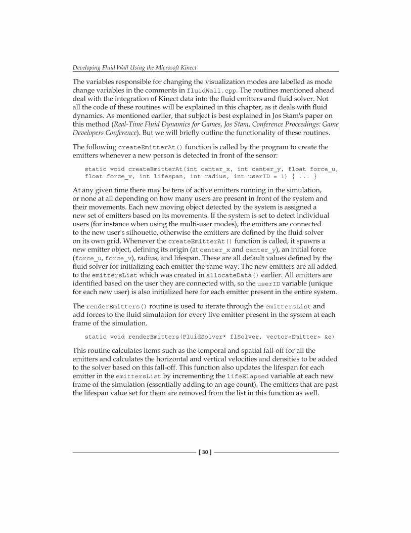
The variables responsible for changing the visualization modes are labelled as mode change variables in the comments in fluidWall.cpp. The routines mentioned ahead deal with the integration of Kinect data into the fluid emitters and fluid solver. Not all the code of these routines will be explained in this chapter, as it deals with fluid dynamics. As mentioned earlier, that subject is best explained in Jos Stam's paper on this method (Real-Time Fluid Dynamics for Games, Jos Stam, Conference Proceedings: Game Developers Conference). But we will briefly outline the functionality of these routines.
The following createEmitterAt() function is called by the program to create the emitters whenever a new person is detected in front of the sensor:
static void createEmitterAt(int center_x, int center_y, float force_u, float force_v, int lifespan, int radius, int userID = 1) { ... }
At any given time there may be tens of active emitters running in the simulation, or none at all depending on how many users are present in front of the system and their movements. Each new moving object detected by the system is assigned a new set of emitters based on its movements. If the system is set to detect individual users (for instance when using the multi-user modes), the emitters are connected to the new user's silhouette, otherwise the emitters are defined by the fluid solver on its own grid. Whenever the createEmitterAt() function is called, it spawns a new emitter object, defining its origin (at center_x and center_y), an initial force (force_u, force_v), radius, and lifespan. These are all default values defined by the fluid solver for initializing each emitter the same way. The new emitters are all added to the emittersList which was created in allocateData() earlier. All emitters are identified based on the user they are connected with, so the userID variable (unique for each new user) is also initialized here for each emitter present in the entire system.
The renderEmitters() routine is used to iterate through the emittersList and add forces to the fluid simulation for every live emitter present in the system at each frame of the simulation.
This routine calculates items such as the temporal and spatial fall-off for all the emitters and calculates the horizontal and vertical velocities and densities to be added to the solver based on this fall-off. This function also updates the lifespan for each emitter in the emittersList by incrementing the lifeElapsed variable at each new frame of the simulation (essentially adding to an age count). The emitters that are past the lifespan value set for them are removed from the list in this function as well.
Chapter 9
[ 31 ]
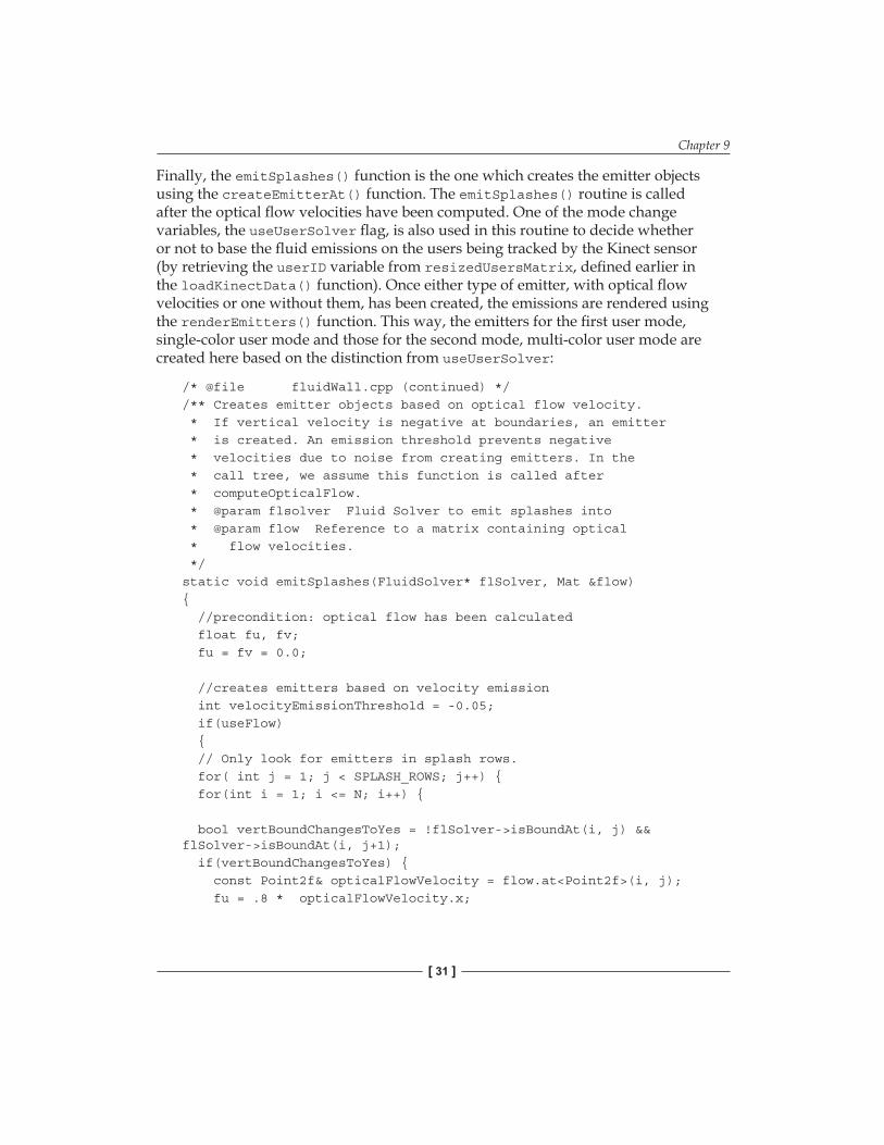
Finally, the emitSplashes() function is the one which creates the emitter objects using the createEmitterAt() function. The emitSplashes() routine is called after the optical flow velocities have been computed. One of the mode change variables, the useUserSolver flag, is also used in this routine to decide whether or not to base the fluid emissions on the users being tracked by the Kinect sensor (by retrieving the userID variable from resizedUsersMatrix, defined earlier in the loadKinectData() function). Once either type of emitter, with optical flow velocities or one without them, has been created, the emissions are rendered using the renderEmitters() function. This way, the emitters for the first user mode, single-color user mode and those for the second mode, multi-color user mode are created here based on the distinction from useUserSolver:
/* @file fluidWall.cpp (continued) *//** Creates emitter objects based on optical flow velocity. * If vertical velocity is negative at boundaries, an emitter * is created. An emission threshold prevents negative * velocities due to noise from creating emitters. In the * call tree, we assume this function is called after * computeOpticalFlow. * @param flsolver Fluid Solver to emit splashes into * @param flow Reference to a matrix containing optical * flow velocities. */static void emitSplashes(FluidSolver* flSolver, Mat &flow){ //precondition: optical flow has been calculated float fu, fv; fu = fv = 0.0;
//creates emitters based on velocity emission int velocityEmissionThreshold = -0.05; if(useFlow) { // Only look for emitters in splash rows. for( int j = 1; j < SPLASH_ROWS; j++) { for(int i = 1; i <= N; i++) {
Another function, getWeightedColor() is responsible for allowing the program to switch between using other fluid modes and the third, white-background user mode. This function simply computes the weighted color for densities of the fluid emitted by each individual user, and the density of the overall system. If the useWhiteBackground flag has been set to true, these densities simply have a white offset added to their color definition.
As for the fourth user mode, it's interesting to note here that the drawOpticalFlow function mentioned in the previous section was originally meant only for debugging, so we could see on screen how the vector field was behaving. But the interesting effects created by vector field interacting with peoples' silhouettes were very compelling to the users who helped us test earlier versions of this program. So, due to a strong demand from these early testers, this functionality ended up being added as one of the application's display modes. The velocities are drawn in the drawVelocity() function as lines from the vector field, where the length and orientation of the lines are defined by each vector's magnitude and direction.
The remaining code in fluidWall.cpp deals with functions used to update the visualization on the screen, change display modes based on user feedback, or after each mode has run its course, and to draw all the fluid densities on screen. The draw functions include routines such as drawVelocity(), drawBounds(), drawDensity(), and drawUsers(). These routines predominantly use OpenGL's GLUT library functions to draw all the objects using polygons and to set per-vertex shading to the polygonal vertices for creating the liquid effects.
Chapter 9
[ 33 ]
The following images show the output fluid with people interacting with it in different modes:
Developing Fluid Wall Using the Microsoft Kinect
[ 34 ]
Current problems and potential improvements for future releasesThe system does have a couple of issues in this current release, which will hopefully be taken care of in later versions:
1. The appearance of the fluid depends on processor speed. Several fluid-simulation parameters that govern emission rates are currently hardcoded. We have discovered that processor speed dramatically affects the way that these parameters work in the simulation. This may cause too much or too little density to be emitted per frame. Future releases should hopefully address this issue and also allow users to adjust these parameters to get the best results for their own machines.
2. The overall structure of the code will need to be improved so as to allow for a more secure sharing of variables. Since the program is currently just a prototype and an open source project not meant for commercial use, the data-sharing among functions is not as protected as can be in an object-oriented application.
3. There are quite a few libraries and hardware consistencies that need to be taken into account for this program to work. At the time of writing this chapter, the disparate libraries, hardware (the Xbox Kinect sensor), and hardware drivers used here are all compatible with each other. However, the specifications or functionalities of any of these components may change and affect the operation of this program in an unexpected manner. We would like to avoid such problems by attempting to use as unified a library and hardware structure as possible. OpenCV's developments adding further support for Kinect data will be especially useful in addressing this particular issue in the future releases.
Chapter 9
[ 35 ]
SummaryFluid wall is a real-time, artistic fluid simulation driven by the Xbox Kinect sensor that responds to viewers' gestures by interacting and colliding with their onscreen silhouettes. The program uses OpenCV for computing optical flow from movement of the viewers in front of the Kinect sensor as well as for providing optional GPU-based optical flow computations through OpenCV's CUDA support. Matrix data structures used throughout the program to save the Kinect's depth and user-tracking data, and data manipulation, resizing, and displaying visual debugging information is also achieved through OpenCV. User-tracking and depth data is acquired from the Kinect using OpenNI's open source drivers. Farneback's method for calculating optical flow, already included in OpenCV, is used in order to apply the correct forces on the fluid simulation to make it interact with viewers' movements. This chapter has given its readers a walkthrough of the implementation and use of these OpenCV and OpenNI libraries and a fast fluid-simulation algorithm in the development of Fluid Wall.