q The views expressed in this paper are those of the authors and not necessarily those of the American Bureau of Shipping. * Corresponding author. Tel.: #1-281-877-6608; fax: #1-281-877-5931. E-mail address: rbasu@eagle.org (R. Basu). Marine Structures 14 (2001) 37} 58 Developing target reliability for novel structures: the case of the Mobile O!shore Base q Baidurya Bhattacharya, Roger Basu*, Kai-tung Ma American Bureau of Shipping,16855 Northchase Drive, Houston, TX 77060-6008, USA Abstract Reliability-based design criteria are usually calibrated to existing structures (of the same class) having a history of successful service. However, as the o!shore industry continues to witness innovations, some novel structures clearly exceed the scope of existing design standards. A reliability-based design is attractive in such cases, but the calibration exercise is not feasible and target reliabilities need to be derived from more fundamental considerations. This paper describes a general risk-based methodology for identifying signi"cant limit states and deriving corresponding target reliabilities for such novel structures. Reliabilities of various existing structures and available analytical methods for determining target reliabilities are reviewed. Careful consideration is given to failure consequences, both tangible and intangible, and reliabilities of intact as well as damaged structures are considered. The methodology is illustrated with the US Navy's Mobile O!shore Base concept, which is a unique o!shore structure in terms of function and size, and for which no precedence or industry standard exists. ( 2001 Elsevier Science Ltd. All rights reserved. Keywords: Structural engineering; Target reliability; System; Risk; Consequence; Limit state; Design; Uncertainty; Safety; Mobile O!shore Base 1. Introduction The objective of every structural design is to develop a structure that is able to perform its functions while meeting the constraints of safety and cost. A well-designed structure should be safe enough against every failure mode, but just so, if it has to be 0951-8339/01/$ - see front matter ( 2001 Elsevier Science Ltd. All rights reserved. PII: S 0 9 5 1 - 8 3 3 9 ( 0 0 ) 0 0 0 2 4 - 1
Transcript
qThe views expressed in this paper are those of the authors and not necessarily those of the AmericanBureau of Shipping.
Developing target reliability for novel structures:the case of the Mobile O!shore Baseq
Baidurya Bhattacharya, Roger Basu*, Kai-tung MaAmerican Bureau of Shipping,16855 Northchase Drive, Houston, TX 77060-6008, USA
Abstract
Reliability-based design criteria are usually calibrated to existing structures (of the sameclass) having a history of successful service. However, as the o!shore industry continues towitness innovations, some novel structures clearly exceed the scope of existing design standards.A reliability-based design is attractive in such cases, but the calibration exercise is not feasibleand target reliabilities need to be derived from more fundamental considerations. This paperdescribes a general risk-based methodology for identifying signi"cant limit states and derivingcorresponding target reliabilities for such novel structures. Reliabilities of various existingstructures and available analytical methods for determining target reliabilities are reviewed.Careful consideration is given to failure consequences, both tangible and intangible, andreliabilities of intact as well as damaged structures are considered. The methodology isillustrated with the US Navy's Mobile O!shore Base concept, which is a unique o!shorestructure in terms of function and size, and for which no precedence or industry standardexists. ( 2001 Elsevier Science Ltd. All rights reserved.
The objective of every structural design is to develop a structure that is able toperform its functions while meeting the constraints of safety and cost. A well-designedstructure should be safe enough against every failure mode, but just so, if it has to be
0951-8339/01/$ - see front matter ( 2001 Elsevier Science Ltd. All rights reserved.PII: S 0 9 5 1 - 8 3 3 9 ( 0 0 ) 0 0 0 2 4 - 1
economical as well. A reliability-based design can address the issue of safety ina transparent and quantitative manner. An important element in this process is thespeci"cation of maximum permissible probabilities of failure (or non-compliance) inall modes that are relevant to the given kind of structure.
The target reliability, which is the complement of the maximum permissible failureprobability, should depend foremost on the consequence of the type of failure inquestion. Possible failure consequences are injury or loss of life, direct and indirecteconomic losses (including repair/replacement costs, loss of revenue, compensationfor damages, etc.), environmental pollution and so on. Consequences should bemeasurable, and all relevant consequences should be included in the analysis. Onemay choose to discount future consequences to their present values, and it has beenargued [1] that future loss of lives be discounted as well. Target reliabilities shouldalso depend on the method of reliability analysis, types of uncertainties included in theanalysis and on future maintenance strategies (e.g., [2]).
The question, `How safe is safe enough?a, needs to be asked when setting thereliability target for a structure. Conventional structures that have a history ofsuccessful service, such as concrete buildings, highway bridges and steel vessels, can bedeemed su$ciently safe, and their reliability levels (determined by analyzing represen-tative structures) may be used as the targets for new structures of the same kind. This,in principle, is done when a new reliability-based code is developed for a given classof structures having a successful history of use [3]. The objective of the new codedevelopment is to produce more uniform levels of safety and more optimal structures.
1.1. The case of novel structures
Calibration of the above sort, however, is di$cult or even impossible, if thestructure is novel with no history of use, or has unusual failure consequences, or if thepace of innovation in the industry is relatively fast. The o!shore industry is continuingto witness innovations in structural concepts and designs. Some of these new conceptsclearly exceed the domain of applicability of existing codes and structures. Therational decision for such structures is to adopt a reliability-based design (e.g., [4]).A reliability-based approach also allows comparison of di!erent competing designson a common basis.
The target reliability (and partial safety factors if an LRFD format is used) requiredin the reliability-based design of such novel structures therefore needs to be derivedfrom less direct, but more rational and, ideally, more fundamental, considerations.This paper presents a general methodology for establishing target reliabilities fornon-generic structures or structures with unusual failure consequences, that is, insituations where calibration is infeasible or insu$cient. The methodology is illustratedwith the US Navy's Mobile O!shore Base concept (MOB, described in Section 1.2),which is a unique o!shore structure in terms of function and size, and for which noprecedence or industry standard exists.
A representative set of reliabilities in various existing codes and structures andexpert recommendations for target reliabilities are "rst summarized (Section 2),following which some of the available analytical methods for deriving target
38 B. Bhattacharya et al. / Marine Structures 14 (2001) 37}58
reliabilities are listed (Section 3). In Section 4, we demonstrate how target reliabilitiesfor di!erent limit states and failure consequences are derived.
1.2. The Mobile Owshore Base
The Mobile O!shore Base (MOB) is conceived as a self-propelled #oating navalbase that can provide a mile-long #at horizontal runway for air operations in the openoceans. It is intended to combine many of the attributes of aircraft carriers, trooptransport and cargo vessels [5]. The MOB will be a unique marine structure in termsof both function and size. Several innovative design concepts have been proposed forMOB. These concepts variously consist of three to six self-propelled semi-submers-ible-type modules (also called SBUs for single base units) connected in series. Con-cepts for the inter-module connectors range from rigid, hinged or #exible bridge-typephysical devices to purely functional connectors where relative positions of the SBUsare maintained by dynamic positioning. There is no precedence, no validated designcapability, no fabrication or operational experience, and no industry standard fora marine structure as large as MOB.
The American Bureau of Shipping (ABS) is developing a reliability-based Classi-"cation Guide for MOB [6] applicable to the range of concepts mentioned above.A rigorous process is being followed for identifying all signi"cant limit states and forestablishing corresponding target reliabilities. Careful consideration is given to failureconsequences, including loss of mission, lives and structure. The in#uence of socio-political factors like national prestige is also incorporated. This process has yieldedtarget reliabilities presented in Section 4 of this paper. Studies are currently underwayto establish the practical impact of these criteria on structural design, and it may benecessary as a consequence of this exercise to adjust target reliabilities such that thecon#icting demands of performance, safety, economy and feasibility are met in abalanced fashion.
2. Existing reliability levels
This section compiles target reliability levels, explicit or implicit, in existing codesand structures. It should be noted that some cases listed here report annual targetreliability, and others report life-time target reliability. One should also note, whilecomparing these values, that `failurea may be de"ned di!erently (e.g., yield or plasticcollapse) and certain uncertainties (especially Type II uncertainties) may have beenneglected in the analyses of some of the codes and projects summarized here.
The terms `reliabilitya and `failure probabilitya both are used in this paper. Therelation between reliability (¸) and failure probability (P
f) is
¸"1!Pf. (1)
Reliability can also be expressed in terms of the generalized reliability index, b:
b"U~1(1!Pf), (2)
B. Bhattacharya et al. / Marine Structures 14 (2001) 37}58 39
Table 1Pf
and generalized reliability index, b
Pf
10~1 10~2 10~3 10~4 10~5 10~6 10~7 10~8
b 1.28 2.32 3.09 3.71 4.25 4.75 5.20 5.60
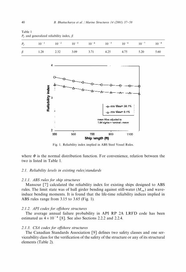
Fig. 1. Reliability index implied in ABS Steel Vessel Rules.
where U is the normal distribution function. For convenience, relation between thetwo is listed in Table 1.
2.1. Reliability levels in existing rules/standards
2.1.1. ABS rules for ship structuresMansour [7] calculated the reliability index for existing ships designed to ABS
rules. The limit state was of hull girder bending against still-water (M48
) and wave-induce bending moments. It is found that the life-time reliability indices implied inABS rules range from 3.15 to 3.65 (Fig. 1).
2.1.2. API codes for owshore structuresThe average annual failure probability in API RP 2A LRFD code has been
estimated as 4]10~4 [8]. See also Sections 2.2.2 and 2.2.4.
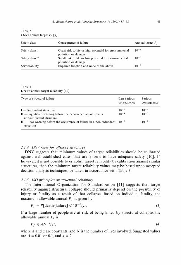
2.1.3. CSA codes for owshore structuresThe Canadian Standards Association [9] de"nes two safety classes and one ser-
viceability class for the veri"cation of the safety of the structure or any of its structuralelements (Table 2).
40 B. Bhattacharya et al. / Marine Structures 14 (2001) 37}58
Table 2CSA's annual targer P
f[9]
Safety class Consequence of failure Annual target Pf
Safety class 1 Great risk to life or high potential for environmentalpollution or damage
10~5
Safety class 2 Small risk to life or low potential for environmentalpollution or damage
10~3
Serviceability Impaired function and none of the above 10~1
Table 3DNV's annual target reliability [10]
Type of structural failure Less seriousconsequence
Seriousconsequence
I * Redundant structure 10~3 10~4
II * Signi"cant warning before the occurrence of failure in anon-redundant structure
10~4 10~5
III * No warning before the occurrence of failure in a non-redundantstructure
10~5 10~6
2.1.4. DNV rules for owshore structuresDNV suggests that minimum values of target reliabilities should be calibrated
against well-established cases that are known to have adequate safety [10]. If,however, it is not possible to establish target reliability by calibration against similarstructures, then the minimum target reliability values may be based upon accepteddecision analysis techniques, or taken in accordance with Table 3.
2.1.5. ISO principles on structural reliabilityThe International Organization for Standardization [11] suggests that target
reliability against structural collapse should primarily depend on the possibility ofinjury or fatality as a result of that collapse. Based on individual fatality, themaximum allowable annual P
fis given by
Pf"P[deathCfailure])10~6/yr. (3)
If a large number of people are at risk of being killed by structural collapse, theallowable annual P
fis
Pf)AN~a/yr, (4)
where A and a are constants, and N is the number of lives involved. Suggested valuesare A"0.01 or 0.1, and a"2.
B. Bhattacharya et al. / Marine Structures 14 (2001) 37}58 41
Table 4Life-time b's in structural standards [12]
Standard Remarks b
AISC LRFD 1984, ANSI A58.1 1982 Gravity loads (dead, snow and live loads) 3.0Gravity#wind 2.5Gravity#earthquake 1.75
Canadian codes for steel, concrete buildings, bridges 30yr lifetime 3.5Eurocode Normal construction 3.5
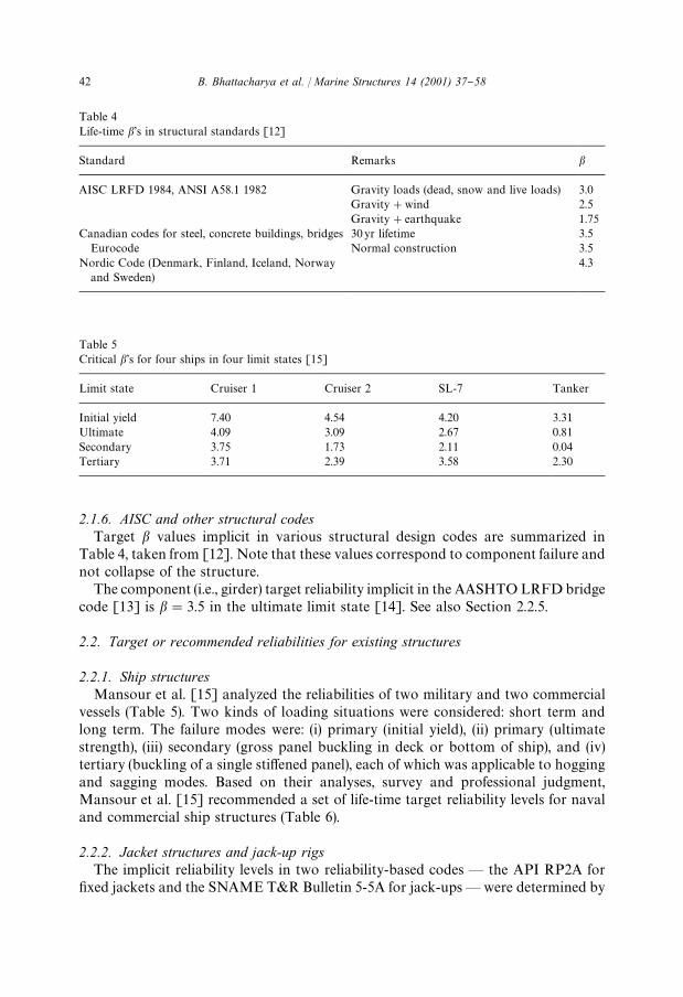
2.1.6. AISC and other structural codesTarget b values implicit in various structural design codes are summarized in
Table 4, taken from [12]. Note that these values correspond to component failure andnot collapse of the structure.
The component (i.e., girder) target reliability implicit in the AASHTO LRFD bridgecode [13] is b"3.5 in the ultimate limit state [14]. See also Section 2.2.5.
2.2. Target or recommended reliabilities for existing structures
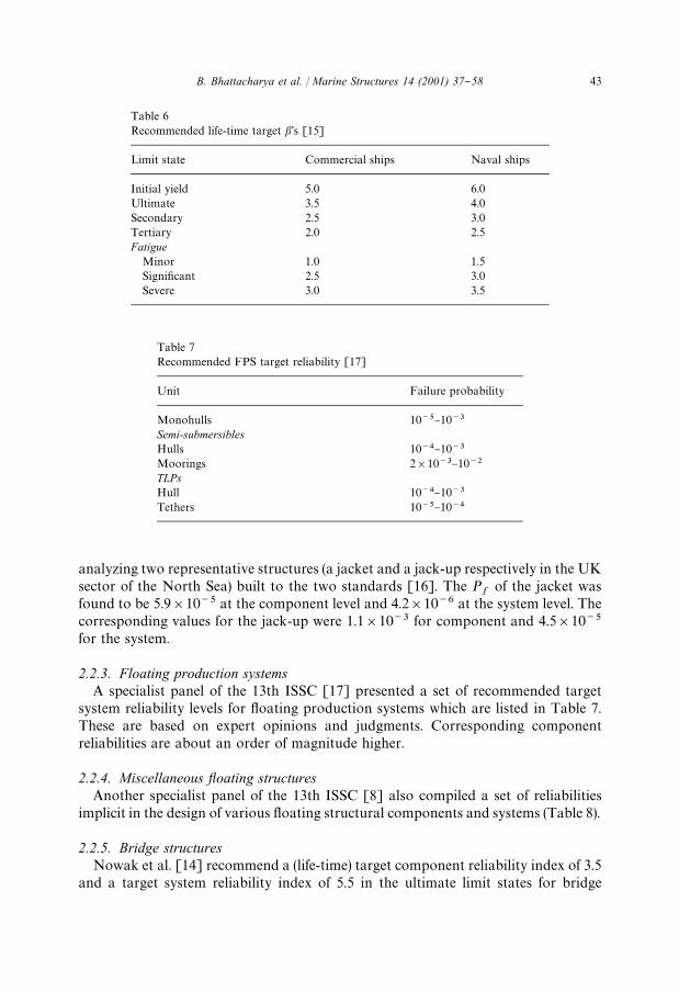
2.2.1. Ship structuresMansour et al. [15] analyzed the reliabilities of two military and two commercial
vessels (Table 5). Two kinds of loading situations were considered: short term andlong term. The failure modes were: (i) primary (initial yield), (ii) primary (ultimatestrength), (iii) secondary (gross panel buckling in deck or bottom of ship), and (iv)tertiary (buckling of a single sti!ened panel), each of which was applicable to hoggingand sagging modes. Based on their analyses, survey and professional judgment,Mansour et al. [15] recommended a set of life-time target reliability levels for navaland commercial ship structures (Table 6).
2.2.2. Jacket structures and jack-up rigsThe implicit reliability levels in two reliability-based codes * the API RP2A for"xed jackets and the SNAME T&R Bulletin 5-5A for jack-ups* were determined by
42 B. Bhattacharya et al. / Marine Structures 14 (2001) 37}58
analyzing two representative structures (a jacket and a jack-up respectively in the UKsector of the North Sea) built to the two standards [16]. The P
fof the jacket was
found to be 5.9]10~5 at the component level and 4.2]10~6 at the system level. Thecorresponding values for the jack-up were 1.1]10~3 for component and 4.5]10~5
for the system.
2.2.3. Floating production systemsA specialist panel of the 13th ISSC [17] presented a set of recommended target
system reliability levels for #oating production systems which are listed in Table 7.These are based on expert opinions and judgments. Corresponding componentreliabilities are about an order of magnitude higher.
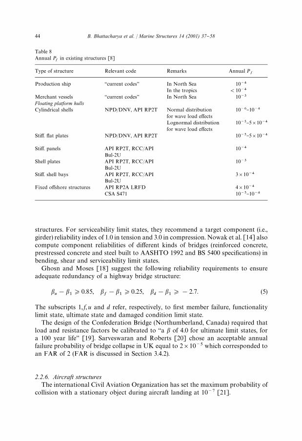
2.2.4. Miscellaneous yoating structuresAnother specialist panel of the 13th ISSC [8] also compiled a set of reliabilities
implicit in the design of various #oating structural components and systems (Table 8).
2.2.5. Bridge structuresNowak et al. [14] recommend a (life-time) target component reliability index of 3.5
and a target system reliability index of 5.5 in the ultimate limit states for bridge
B. Bhattacharya et al. / Marine Structures 14 (2001) 37}58 43
Table 8Annual P
fin existing structures [8]
Type of structure Relevant code Remarks Annual Pf
Production ship `current codesa In North Sea 10~4
In the tropics (10~4
Merchant vessels `current codesa In North Sea 10~3
Floating platform hullsCylindrical shells NPD/DNV, API RP2T Normal distribution
for wave load e!ects10~6}10~4
Lognormal distributionfor wave load e!ects
10~5}5]10~4
Sti!. #at plates NPD/DNV, API RP2T 10~5}5]10~4
Sti!. panels API RP2T, RCC/APIBul-2U
10~4
Shell plates API RP2T, RCC/APIBul-2U
10~3
Sti!. shell bays API RP2T, RCC/APIBul-2U
3]10~4
Fixed o!shore structures API RP2A LRFD 4]10~4
CSA S471 10~5}10~4
structures. For serviceability limit states, they recommend a target component (i.e.,girder) reliability index of 1.0 in tension and 3.0 in compression. Nowak et al. [14] alsocompute component reliabilities of di!erent kinds of bridges (reinforced concrete,prestressed concrete and steel built to AASHTO 1992 and BS 5400 speci"cations) inbending, shear and serviceability limit states.
Ghosn and Moses [18] suggest the following reliability requirements to ensureadequate redundancy of a highway bridge structure:
bu!b
1*0.85, b
f!b
1*0.25, b
d!b
1*!2.7. (5)
The subscripts 1, f, u and d refer, respectively, to "rst member failure, functionalitylimit state, ultimate state and damaged condition limit state.
The design of the Confederation Bridge (Northumberland, Canada) required thatload and resistance factors be calibrated to `a b of 4.0 for ultimate limit states, fora 100 year lifea [19]. Sarveswaran and Roberts [20] chose an acceptable annualfailure probability of bridge collapse in UK equal to 2]10~5 which corresponded toan FAR of 2 (FAR is discussed in Section 3.4.2).
2.2.6. Aircraft structuresThe international Civil Aviation Organization has set the maximum probability of
collision with a stationary object during aircraft landing at 10~7 [21].
44 B. Bhattacharya et al. / Marine Structures 14 (2001) 37}58
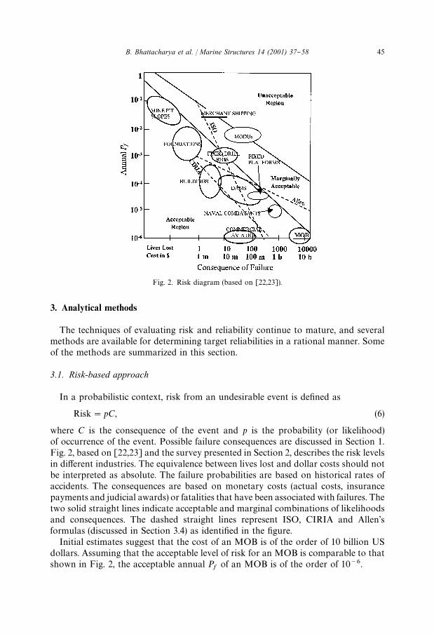
Fig. 2. Risk diagram (based on [22,23]).
3. Analytical methods
The techniques of evaluating risk and reliability continue to mature, and severalmethods are available for determining target reliabilities in a rational manner. Someof the methods are summarized in this section.
3.1. Risk-based approach
In a probabilistic context, risk from an undesirable event is de"ned as
Risk"pC, (6)
where C is the consequence of the event and p is the probability (or likelihood)of occurrence of the event. Possible failure consequences are discussed in Section 1.Fig. 2, based on [22,23] and the survey presented in Section 2, describes the risk levelsin di!erent industries. The equivalence between lives lost and dollar costs should notbe interpreted as absolute. The failure probabilities are based on historical rates ofaccidents. The consequences are based on monetary costs (actual costs, insurancepayments and judicial awards) or fatalities that have been associated with failures. Thetwo solid straight lines indicate acceptable and marginal combinations of likelihoodsand consequences. The dashed straight lines represent ISO, CIRIA and Allen'sformulas (discussed in Section 3.4) as identi"ed in the "gure.
Initial estimates suggest that the cost of an MOB is of the order of 10 billion USdollars. Assuming that the acceptable level of risk for an MOB is comparable to thatshown in Fig. 2, the acceptable annual P
fof an MOB is of the order of 10~6.
B. Bhattacharya et al. / Marine Structures 14 (2001) 37}58 45
3.2. Life-cycle cost analysis
Target reliabilities can be chosen to minimize the expected total cost over theservice life of the system. A simpli"ed expression for the expected total cost, E[C
T], is
E[CT]"C
I#C
FPf, (7)
where CI, and C
Fare, respectively, initial and failure costs. C
Iis generally an
increasing function of the reliability index, b (see, e.g., [24]). Recall that b is related toPf
through Eq. (2). E[CT] may be minimized with respect to b, with or without
constraints as appropriate, yielding the target reliability index. Recent applications ofthis method, which include discounting of future costs, can be found in [25,26]. This isa versatile and attractive method. However, estimates of C
Ias a function of b are not
yet available for an MOB.
3.3. Experience and calibration
Design standards traditionally evolve with experience and judgment. Factors thata!ect this process include improved analysis tools, new materials, better insight intostructural behavior, and, notably, serious accidents. Ronin Point, Alexander Keilland,Exxon Valdez and failures of bulk carriers over the last decade or so are examples ofdisasters resulting in enhancement of codes/rules. When new reliability-based designcodes are developed, they take advantage of this knowledge-base through calibrationand other checks. However, as mentioned in Section 1.1, this type of exercise issuitable for near-generic structures with su$cient history, and therefore inadequatefor novel structures or structures with unusual failure consequences.
3.4. Social acceptance criteria involving fatalities
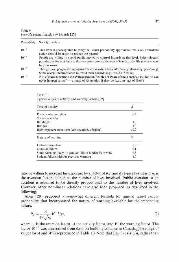
3.4.1. Acceptable annual probabilities of failureSociety's general reaction to hazards of di!erent levels [27] are listed in Table 9. If
exposure to an activity is voluntary, the acceptable level of risk is generally higher.Various agencies and researchers have investigated levels of probability that areacceptable to society for events causing fatalities, as described in the following. Theacceptable probabilities depend on the nature of the hazard, and decrease withincreasing number of fatalities. However, it needs to be underlined that a society'ssense of tolerable risk for a given activity may change with time.
In a CIRIA report [28], Flint developed an empirical formula for setting the annualtarget failure probability as
Pf"
Ks
nr
p@/yr, (8)
where p@ is the basic annual probability of death accepted by an individual member ofsociety. According to this reference, a typical value in the UK is 10~4. K
sis the social
criterion factor. It accounts for the voluntary nature of hazardous activity (a person
46 B. Bhattacharya et al. / Marine Structures 14 (2001) 37}58
Table 9Society's general reaction to hazards [27]
Probability Society reaction
10~3 This level is unacceptable to everyone. When probability approaches this level, immediateaction should be taken to reduce the hazard
10~4 People are willing to spend public money to control hazards at this level. Safety sloganspopularized for accidents in this category show an element of fear (e.g., the life you save maybe your own)
10~5 Though rare, people still recognize these hazards, warn children (e.g., drowning, poisoning).Some accept inconvenience to avoid such hazards (e.g., avoid air travel)
10~6 Not of great concern to the average person. People are aware of these hazards, but feel `it cannever happen to mea * a sense of resignation if they do (e.g., an `act of Goda)
Table 10Typical values of activity and warning factors [29]
Fail-safe condition 0.01Gradual failure 0.1Some warning likely or gradual failure hidden from view 0.3Sudden failure without previous warning 1.0
may be willing to increase his exposure by a factor of Ks) and its typical value is 5. n
ris
the aversion factor de"ned as the number of lives involved. Public aversion to anaccident is assumed to be directly proportional to the number of lives involved.However, other non-linear relations have also been proposed, as described in thefollowing.
Allen [29] proposed a somewhat di!erent formula for annual target failureprobability that incorporated the nature of warning available for the impendingfailure:
Pf"
A
=Jnr
10~5/yr, (9)
where nris the aversion factor, A the activity factor, and= the warning factor. The
factor 10~5 was ascertained from data on building collapse in Canada. The range ofvalues for A and= is reproduced in Table 10. Note that Eq. (9) uses Jn
rrather than
B. Bhattacharya et al. / Marine Structures 14 (2001) 37}58 47
nrin the denominator implying that the rate of growth in risk aversion decreases with
the number of fatalities.More recently, ISO [11] has tied the acceptable failure probability to the square of
the number of lives involved (Eq. (4)), signifying perhaps a decrease in the public'ssense of tolerable risk in engineered systems.
To set the target reliability for MOB from social acceptance criteria, assume thereare 1000 personnel onboard. Flint's formula (Eq. (8)), using K
s"5, yields an annual
target failure probability of 5]10~7. Alternately, Allen's formula (Eq. (9)), withA"10.0 and="0.1, gives the annual target of 3.2]10~5. At the other end of thespectrum, the ISO requirement (Eq. (4) with A"0.1) yields the target of 10~7/yr. Thethree formulas are compared in Fig. 2. It should be noted here that military structuresare expected to be governed by a di!erent set of parameters p@, K
s, A,=, etc. which,
unfortunately, are unavailable for an MOB at this stage. Nevertheless, it is observedthat there is a wide variability in the acceptable annual target reliabilities proposed bymethods that consider fatalities alone.
3.4.2. Fatal accident rateA somewhat di!erent measure of hazardous activities that accounts for exposure
time is the fatal accident rate (FAR). The FAR for an activity is the number of fatalitiesper 100 million hours of exposure to that activity (i.e., 1000 people working 2500ha year and having working lives of 40 yr each):
FAR"108P[F]/¹h, (10)
where P[F] is probability of fatality, and ¹h
is the exposure time in person-hours.Typical values of FAR in the UK [30] range from 5 (chemical processing industry) to67 (construction industry). FARs for various activities in Japan are listed in [31] andthese range from 0.2 for "res, 4.3 for railway travel to 46.3 for civil aviation. Thepresent study, however, has not been able to locate acceptable FARs (or similarcriteria) for military activities.
4. Developing target reliabilities
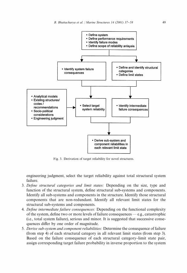
A general methodology for setting target reliabilities for all relevant limit states ofa novel structure is presented in this section. The target system reliability is selected"rst. The component target reliabilities are then assigned on a uniform risk basis. Thebasic steps are (Fig. 3):
1. Identify system failure consequence: Clearly de"ne the structural system and identifyall system failure modes. Identify all consequences of total structural system failure,and express consequences in measurable quantities (dollars, lives, etc.). Note anyunusual or intangible failure consequence. De"ne scope of reliability analysisincluding types of uncertainty to be included in the analysis.
2. Select target system reliability: Using a combination of analytical models, surveyof existing codes and structures, socio-political considerations and basing on
48 B. Bhattacharya et al. / Marine Structures 14 (2001) 37}58
Fig. 3. Derivation of target reliability for novel structures.
engineering judgment, select the target reliability against total structural systemfailure.
3. Dexne structural categories and limit states: Depending on the size, type andfunction of the structural system, de"ne structural sub-systems and components.Identify all sub-systems and components in the structure. Identify those structuralcomponents that are non-redundant. Identify all relevant limit states for thestructural sub-systems and components.
4. Dexne intermediate failure consequences: Depending on the functional complexityof the system, de"ne two or more levels of failure consequences* e.g., catastrophic(i.e., total system failure), serious and minor. It is suggested that successive conse-quences di!er by one order of magnitude.
5. Derive sub-system and component reliabilities: Determine the consequence of failure(from step 4) of each structural category in all relevant limit states (from step 3).Based on the failure consequence of each structural category}limit state pair,assign corresponding target failure probability in inverse proportion to the system
B. Bhattacharya et al. / Marine Structures 14 (2001) 37}58 49
target selected in step 2:
Pi,jf"
C4:4
Ci,j
Pf,4:4
, (11)
where C4:4
and Pf,4:4
are, respectively, the consequence and target probability ofsystem failure. C
i,jand Pi,j
fare, respectively, the consequence and target probability
of component (or sub-system) i exceeding limit state j. Note that only ratios ofconsequences are required.
Application of this general methodology to an MOB structure is described inSections 4.1}4.5. It is based on the material presented in Sections 2 and 3, as well as onthe deliberations conducted over two years in the MOB Standards and CriteriaWorking Group formed as part of the MOB Science and Technology Program.
4.1. System failure
The MOB is a mile-long ocean-going #oating structure that is required to maintainan approximately straight and horizontal runway surface up to moderate sea states.The possible total system failure (i.e., global failure) modes of an MOB are: (i) sinking,(ii) capsizing, and (iii) loss of station-keeping.
It is important to note that for a #oating structure, system failure may take place ina sequence of structural failures, #ooding events or an inter-dependent combination ofthese. The cause of failure may be extreme environmental events, weapons e!ects oraccidental explosions; or failure may simply be triggered by equipment failure (valves,hatches, etc.) or operational failures (e.g., loss of dynamic positioning).
The consequences of total failure of MOB structural system include:
1. Loss of lives: Up to 3000 troops [5] and a large crew can be onboard a fullyoperational MOB.
2. Loss of mission: The MOB will be a #oating naval base required to conduct #ight,maintenance, supply and other military support operations.
3. Loss of morale and national prestige: The MOB will be a high-visibility one-of-a-kind military asset.
4. Loss of property and assets: According to initial estimates, the cost of building MOBis of the order of 10 billion US dollars.
5. Pollution: The MOB is expected to carry liquid as well as solid cargo, some ofwhich may be hazardous.
4.2. Target system reliability
While determining the target system reliability for an MOB, it is noted that (i) thereis no truly comparable #oating structure (in terms of cost and complexity) that couldprovide a reliable benchmark, and (ii) there are `intangiblea consequences of MOBfailure (like mission failure and loss of national prestige) to which it is di$cult toassign dollar or loss-of-life values. Nevertheless, an optimal target needs to be foundso that a very high reliability does not come in the way of performance and e$ciency.
50 B. Bhattacharya et al. / Marine Structures 14 (2001) 37}58
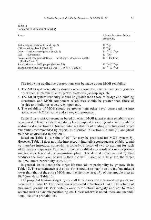
Table 11Comparative estimates of target P
f
Source Allowable system failureprobability
Risk analysis (Section 3.1 and Fig. 2) 10~6/yrCSA * safety class 1 (Table 2) 10~5/yrDNV * serious consequence (Table 3) 10~6}10~5/yrISO * 1000 people 10~7/yrProfessional recommendations* naval ships, ultimate strength
(Tables 6 and 7)10~5 life time
Social criteria * 1000 people (Section 3.4) 10~7}10~5/yrExisting structures (Section 2.2, Fig. 1, Tables 4, 7 and 8) 10~7}10~3/yr
The following qualitative observations can be made about MOB reliability:
1. The MOB system reliability should exceed those of all commercial #oating struc-tures such as merchant ships, jacket platforms, jack-up rigs, etc.
2. The MOB system reliability should be greater than those of bridge and buildingstructures, and MOB component reliabilities should be greater than those ofbridge and building structure components.
3. The reliability of MOB should be greater than other naval vessels taking intoaccount its (MOB's) value and strategic importance.
Table 11 lists various estimates based on which MOB target system reliability maybe assigned. These include (i) reliability levels implicit in existing rules and standardsas discussed in Section 2.1, (ii) computed reliabilities of existing structures and targetreliabilities recommended by experts as discussed in Section 2.2, and (iii) analyticalmethods as discussed in Section 3.
Based on Table 11, a value of 10~7/yr may be proposed for MOB system Pf
.However, Table 11 does not take into account intangible consequences of failure, andwe therefore introduce, somewhat arbitrarily, a factor of two to account for suchadditional consequences. This factor may be modi"ed as a result of a more rigorousanalysis undertaken at the acquisition phase. The desired target annual P
fthat
produces the same level of risk is then 5]10~8. Based on a 40 yr life, the targetlife-time failure probability is 2]10~6.
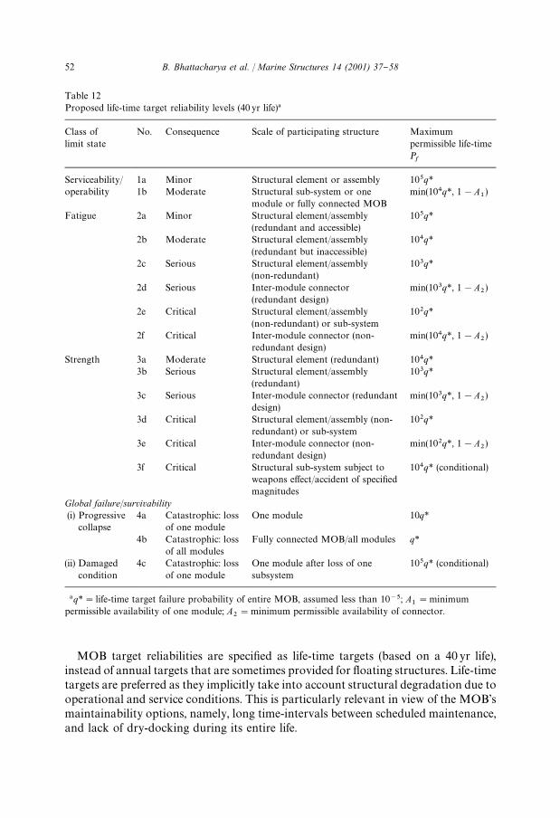
In general, let us denote the target life-time failure probability by q* (row 4b inTable 12). The consequence of the loss of one module is roughly an order of magnitudelower than that of the entire MOB, and the life-time target P
fof one module is set at
10q* (row 4a in Table 12).The proposed life-time target P
f's for all limit states and structural categories are
presented in Table 12. The derivation is presented in Sections 4.3}4.5. The column ofmaximum permissible P
f's pertains only to structural integrity and not to other
systems such as dynamic positioning, etc. Unless otherwise noted, these are uncondi-tional life-time probabilities.
B. Bhattacharya et al. / Marine Structures 14 (2001) 37}58 51
Table 12Proposed life-time target reliability levels (40 yr life)!
Class oflimit state
No. Consequence Scale of participating structure Maximumpermissible life-timePf
Serviceability/operability
1a Minor Structural element or assembly 105q*1b Moderate Structural sub-system or one
module or fully connected MOBmin(104q*, 1!A
1)
Fatigue 2a Minor Structural element/assembly(redundant and accessible)
105q*
2b Moderate Structural element/assembly(redundant but inaccessible)
3d Critical Structural element/assembly (non-redundant) or sub-system
102q*
3e Critical Inter-module connector (non-redundant design)
min(102q*, 1!A2)
3f Critical Structural sub-system subject toweapons e!ect/accident of speci"edmagnitudes
104q* (conditional)
Global failure/survivability(i) Progressive
collapse4a Catastrophic: loss
of one moduleOne module 10q*
4b Catastrophic: lossof all modules
Fully connected MOB/all modules q*
(ii) Damagedcondition
4c Catastrophic: lossof one module
One module after loss of onesubsystem
105q* (conditional)
!q*"life-time target failure probability of entire MOB, assumed less than 10~5; A1"minimum
permissible availability of one module; A2"minimum permissible availability of connector.
MOB target reliabilities are speci"ed as life-time targets (based on a 40 yr life),instead of annual targets that are sometimes provided for #oating structures. Life-timetargets are preferred as they implicitly take into account structural degradation due tooperational and service conditions. This is particularly relevant in view of the MOB'smaintainability options, namely, long time-intervals between scheduled maintenance,and lack of dry-docking during its entire life.
52 B. Bhattacharya et al. / Marine Structures 14 (2001) 37}58
4.3. Structural categories and limit states
Current MOB concepts variously envision an MOB to be composed of 3}6modules connected in series. Each of these modules, which typically have a semi-submersible form, is also capable of operating and transiting individually. Like anycomplex structural system, an MOB is composed of various structural subsystems,which in turn are composed of numerous structural elements and assemblies. Sincetarget reliabilities are assigned based, among others, on scale of structural involve-ment, it is important to de"ne these terms precisely:
1. Structural element: A structural element is the simplest structural unit, such asa tubular member, a longitudinal, a sti!ener or a connection.
2. Structural assembly: A structural assembly is a collection of elements structurallyconnected, such as a sti!ened plate panel or a bulkhead. Several structural elementsconstitute a structural assembly. An element or an assembly is also referred to as astructural component.
3. Structural sub-system: A sub-system refers to a major constituent of an SBU, such asdeck, pontoon or column. Several structural elements and assemblies constitutea structural sub-system.
4. Structural system: The structural system refers to the entire MOB in its connectedstate, and to an individual SBU (module) when disconnected. Several structuralsub-systems constitute the structural system.
5. Connector: Due to the uniqueness of the inter-module connectors and the widedi!erences in their concept designs, inter-module connectors have been placed in aseparate category, but are equivalent to a structural sub-system in importance.
More detailed de"nition may be necessary when a particular MOB concept isselected for further evaluation.
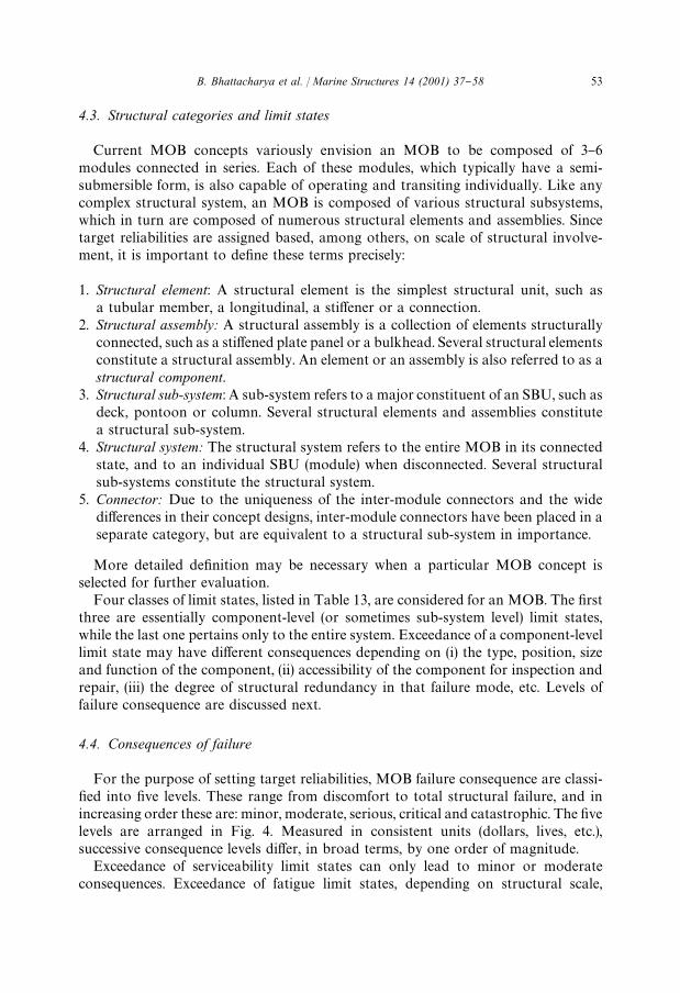
Four classes of limit states, listed in Table 13, are considered for an MOB. The "rstthree are essentially component-level (or sometimes sub-system level) limit states,while the last one pertains only to the entire system. Exceedance of a component-levellimit state may have di!erent consequences depending on (i) the type, position, sizeand function of the component, (ii) accessibility of the component for inspection andrepair, (iii) the degree of structural redundancy in that failure mode, etc. Levels offailure consequence are discussed next.
4.4. Consequences of failure
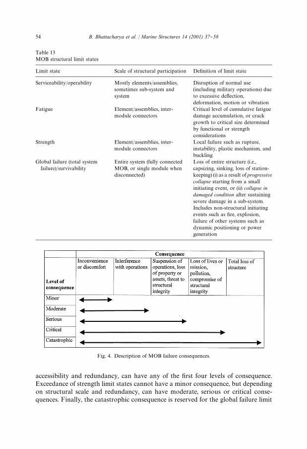
For the purpose of setting target reliabilities, MOB failure consequence are classi-"ed into "ve levels. These range from discomfort to total structural failure, and inincreasing order these are: minor, moderate, serious, critical and catastrophic. The "velevels are arranged in Fig. 4. Measured in consistent units (dollars, lives, etc.),successive consequence levels di!er, in broad terms, by one order of magnitude.
Exceedance of serviceability limit states can only lead to minor or moderateconsequences. Exceedance of fatigue limit states, depending on structural scale,
B. Bhattacharya et al. / Marine Structures 14 (2001) 37}58 53
Table 13MOB structural limit states
Limit state Scale of structural participation De"nition of limit state
Local failure such as rupture,instability, plastic mechanism, andbuckling
Global failure (total systemfailure)/survivability
Entire system (fully connectedMOB, or single module whendisconnected)
Loss of entire structure (i.e.,capsizing, sinking, loss of station-keeping) (i) as a result of progressivecollapse starting from a smallinitiating event, or (ii) collapse indamaged condition after sustainingsevere damage in a sub-system.Includes non-structural initiatingevents such as "re, explosion,failure of other systems such asdynamic positioning or powergeneration
Fig. 4. Description of MOB failure consequences.
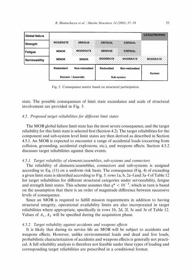
accessibility and redundancy, can have any of the "rst four levels of consequence.Exceedance of strength limit states cannot have a minor consequence, but dependingon structural scale and redundancy, can have moderate, serious or critical conse-quences. Finally, the catastrophic consequence is reserved for the global failure limit
54 B. Bhattacharya et al. / Marine Structures 14 (2001) 37}58
Fig. 5. Consequence matrix based on structural participation.
state. The possible consequences of limit state exceedance and scale of structuralinvolvement are provided in Fig. 5.
4.5. Proposed target reliabilities for diwerent limit states
The MOB global failure limit state has the most severe consequence, and the targetreliability for this limit state is selected "rst (Section 4.2). The target reliabilities for thecomponent and sub-system level limit states are then derived as described in Section4.5.1. An MOB is expected to encounter a range of accidental loads (occurring fromcollision, grounding, accidental explosions, etc.), and weapons e!ects. Section 4.5.2discusses target reliabilities against these events.
4.5.1. Target reliability of elements/assemblies, sub-systems and connectorsThe reliability of elements/assemblies, connectors and sub-systems is assigned
according to Eq. (11) on a uniform risk basis. The consequence (Fig. 4) of exceedinga given limit state is identi"ed according to Fig. 5. rows 1a, b, 2a}f and 3a}f of Table 12list target reliabilities for di!erent structural categories under serviceability, fatigueand strength limit states. This scheme assumes that q*(10~5, which in turn is basedon the assumption that there is an order of magnitude di!erence between successivelevels of consequence.
Since an MOB is required to ful"ll mission requirements in addition to havingstructural integrity, operational availability limits are also incorporated in targetreliabilities where appropriate, speci"cally in rows 1b, 2d, 2f, 3c and 3e of Table 12.Values of A
1, A
2will be speci"ed during the acquisition phase.
4.5.2. Target reliability against accidents and weapons ewectsIt is likely that during its service life an MOB will be subject to accidents and
weapons e!ects. However, unlike environmental loads and dead and live loads,probabilistic characterization of accidents and weapons e!ects is generally not practi-cal. A full reliability analysis is therefore not feasible under these types of loading andcorresponding target reliabilities are prescribed in a conditional format.
B. Bhattacharya et al. / Marine Structures 14 (2001) 37}58 55
The sub-system target reliability under weapons e!ect (row 3f of Table 12) isconditional on a speci"ed weapons load or a speci"ed accidental event. This eventoccurs at any potential location within the sub-system and is expected to causesubstantial local structural damage at the element/assembly level.
The damaged condition limit states represent global failure occurring after theMOB sustains severe damage in a structural sub-system. Such damage may be theresult of accidents (e.g., grounding, collision, "re) or weapons e!ects (explosions, shockwaves, etc.), and is quanti"ed by removal of a structural sub-system at a time.Consequently, irrespective of how the damage occurs, row 4c of Table 12 prescribesthe target reliability conditional on the damage.
5. Summary and conclusion
This paper addresses the problem of setting design criteria for structures for whichthere is no direct experience; the subject structure in this case is the US Navy's MobileO!shore Base. As discussed in the paper, a reliability-based framework is consideredthe most appropriate for such structures, where the criteria are expressed in terms oftarget reliabilities. The reliability-based framework should also specify future main-tenance strategies and the scope of the reliability analysis including uncertainties thatshould be considered in the analysis.
A survey of reliability levels in existing design standards and engineered structures,target reliabilities recommended by experts, and analytical models for establishingacceptable failure probabilities is presented.
In the absence of experience and history, `calibrationa, as commonly applied in thedevelopment of LRFD standards, is not an option. This paper presents a generalmethodology for establishing target reliabilities for novel or unique structures or forstructures with unusual failure consequences. A risk-based approach is employed todevelop a hierarchy of target reliability levels which takes into account the failuremode considered and the consequence of failure. A key parameter is the extent ofparticipation of the structure in the failure mode in question.
The methodology is illustrated with the MOB. The MOB target reliabilitiespresented here are subject to modi"cation in the actual acquisition phase when moreinput becomes available. It is emphasized that setting target reliabilities for high-valuenovel structures is not an engineering decision alone: active involvement on the part ofthe owners and policy-makers is also required.
Acknowledgements
This paper elaborates upon a short paper [32] presented at the Third InternationalWorkshop on Very Large Floating Structures held at Honolulu, Hawaii, USA, inSeptember 1999. The work described in this paper was performed as part of theMobile O!shore Base Classi"cation Guide development project undertaken by theAmerican Bureau of Shipping. The authors wish to thank the O$ce of Naval
56 B. Bhattacharya et al. / Marine Structures 14 (2001) 37}58
Research for sponsoring this project as part of the MOB Science & TechnologyProgram. Oversight of this project was provided by the Standards and CriteriaWorking Group chaired by Dr. Theodore Shugar of Naval Facilities EngineeringService Center, Port Hueneme, CA.
References
[1] Lind NC. Target reliability levels from social indicators. Proceedings of the Sixth InternationalConference on Structural Safety and Reliability, Innsbruck, Austria, 1993. p. 1897}904.
[2] Moan T. Target levels for reliability-based reassessment of o!shore structures. Proceedings of theSeventh International Conference on Structural Safety and Reliability, Kyoto, Japan, 1997.p. 2049}56.
[4] Moan T. Current trends in the safety of o!shore structures, vol. IV. Proceedings of the EighthInternational O!shore and Polar Engineering Conference, Honolulu, 1997.
[5] Remmers G, Zueck R, Palo P, Taylor R. Mobile o!shore base. Proceedings of the Eighth Interna-tional O!shore and Polar Engineering Conference, Montreal, Canada, 1998.
[6] American Bureau of Shipping (ABS). Draft mobile o!shore base classi"cation guide (proprietarypublication subject to restricted distribution). ABS, Houston, TX, 1999.
[7] Mansour AE. An introduction to structural reliability theory. Ship Structure Committee ReportSSC-351, Washington, DC, 1990.
[8] Committee IV.1. Design principles and criteria. Proceedings of the 13th International Ship andO!shore Structures Congress, Trondheim, Norway, 1997.
[9] Canadian Standards Association. General requirements, design criteria, the environment, and loads,a national standard of Canada. CAN/CSA-S471-92, 1992.
[10] Det Norske Veritas. Structural reliability analysis of marine structures, classi"cation notes no. 30.6.DNV, Norway, 1992.
[11] International Organization for Standardization. General principles on reliability for structures. ISO2394, 1998.
[13] American Association of State Highway and Transportation O$cials. LRFD bridge design speci"ca-tions. AASHTO, Washington, DC, 1994.
[14] Nowak AS, Szerszen MM, Park CH. Target safety levels for bridges. Proceedings of the SeventhInternational Conference on Structural Safety and Reliability, Kyoto, Japan, 1997. p. 1897}903.
[15] Mansour AE, Wirsching P, Luckett M, Plumpton A. Assessment of reliability of existing shipstructures. Ship Structure Committee Report No. SSC-398, Washington, DC, 1997.
[16] MSL Engineers Limited. Reliability of "xed and jack-up structures. Draft Final Report, 1996.[17] Committee V.6. Structural design of #oating production systems. Proceedings of the 13th Interna-
tional Ship and O!shore Structures Congress, Trondheim, Norway, 1997.[18] Ghosn M, Moses F. Redundancy in highway bridge superstructures. Report 406, Transportation
Research Board, Washington DC: National Academy Press, 1998.[19] MacGregor JG, Kennedy OSL, Bartlett FM, Chernenko D, Maes MA, Dunaszegi L. Design criteria
and load and resistance factors for the Confederation Bridge. Can J Civil Engng 1997;24:882}97.[20] Sarveswaran V, Roberts MB. Reliability analysis of deteriorating structures * the experience and
needs of practising engineers. Struct Safety 1999;21:357}72.[21] Polky JN, Held JT. Analysis of the collision risk for aircraft operation on a mobile o!shore air"eld.
Proceedings of the 22nd UJNR Marine Facilities Panel Meeting, Arlington, VA, 1998.[22] Whitman R. Evaluating calculated risk in geotechnical engineering. J Geotech Engng ASCE
1984;110(2):145}88.
B. Bhattacharya et al. / Marine Structures 14 (2001) 37}58 57
[23] Cullen HN. The public inquiry into the Piper Alpha disaster. Technical Report, The Parliament bythe Secretary of the State for Energy, UK, 1990.
[24] Bea RG. Reliability based design criteria for coastal and ocean structures. Australia: The Institutionof Engineers, 1990.
[25] Ang AH-S, De Leon D. Determination of optimal target reliabilities for design and upgrading ofstructures. Struct Safety 1997;19:91}103.
[26] Wen YK, Kang YJ. Minimum life-cycle cost design criteria. Proceedings of the Seventh InternationalConference on Structural Safety and Reliability, Kyoto, Japan, 1997. p. 1047}54.
[27] Keese DL, Barton WR. Risk assessment and its application to #ight safety analysis. Sandia NationalLaboratories, SAND89, 1982.
[28] Construction Industry Research and Information Association. Rationalization of safety and servicea-bility factors in structural codes. CIRIA, Report No. 63, London, 1977.
[29] Allen DE. Criteria for design safety factors and quality assurance expenditure. Proceedings of theThird International Conference on Structural Safety and Reliability, Trondheim, Norway, 1981.p. 667}78.
[30] Mander JB, Elms DG. Quantitative risk assessment of large structural systems. Proceedings ofthe Sixth International Conference on Structural Safety and Reliability, Innsbruck, Austria, 1993.p. 1905}12.
[31] Suzuki H. Safety target of very large #oating structure used as a #oating airport. Proceedings ofthe Third International Workshop on Very Large Floating Structures. Honolulu, Hawaii, 1999.p. 607}12.
[32] Bhattacharya B, Ma K-T, Basu R. Developing target reliability for novel structures: the case of theMobile O!shore Base. Proceedings of the Third International Workshop on Very Large FloatingStructures, Honolulu, Hawaii, 1999, p. 398}407.
58 B. Bhattacharya et al. / Marine Structures 14 (2001) 37}58