Development and Control of a Three DOF Planar Induction Motor Masaaki Kumagai and Ralph L. Hollis Abstract— This paper reports a planar induction motor that can output 70N translational thrust and 9Nm torque within response time of 10ms. This motor consists of three linear induction armatures with vector control driver and three optical mouse sensors. First, an idea to combine linear induction motor is proposed. The power distribution to each element is derived from position and orientation of it. Then, developed system and its measured characteristics follow. Experimental results indicate potential of its direct drive feature. I. INTRODUCTION Omnidirectional actuation is one of desirable capabilities for mobile robots. Most of those robots achieve omni- directional motion by using special wheels connecting to general rotary motors through reduction gears. Though these configurations work well, two major limitations arise. One is transmission error such as backlash that degrades accuracy and delay in response. The other is slip due to limitation in friction force between the wheels and a floor where the robot is on, which limit maximum acceleration of the robot. To solve these two problems, direct-drive planar actuator is favorable. Many of planar actuators were developed by applying principles of rotary motors. For example, Lauwers et al. reported a robot with planar actuator based on stepper motor[1], which archived very precise positioning. Several types of planar motors were surveyed in a report[2]. One group of planar motors in based on induction motor. A linear induction motor (LIM) is one of successful linear motor that is a combination of an armature and a reaction plate, which is rather simple motor. By using more than two motors, at least, 3-DOF (translation and rotation) planar motor can be achieved. Dittrich et al. developed planar induction motor on such idea[3]. They used four LIMs for their motor, and measured steady characteristics. They also formed a closed loop for position control. An interesting motor was proposed by Fujii et al.[4]. It had a circular shape armature, and windings at a part of the arc work as an individual curved linear motor. They reported advantage in efficiency than simple combination of LIMs, whereas there is no freedom in armature arrangement. However, these works did not mention dynamic control or response while these features are important for robot control. Our motivation is to develop and control the planar induction motor (PIM) with sufficient dynamic response. We already reported planar motion detection method using Masaaki Kumagai is with the Faculty of Engineering, Tohoku Gakuin University, Tagajo 985-8537 Japan. Ralph L. Hollis is with The Robotics Institute, Carnegie Mellon University, Pittsburgh, PA 15213, USA. [email protected], [email protected]Core lamination Windings Armature Conducting plate Reaction plate Back iron plate Gap Pitch Fig. 1. A model of linear induction motor. optical mouse sensors[5] and high-response LIM with own vector controller[6]. A PIM of up to 70N translational thrust and 9Nm torque with 10ms response was developed using these basis and control equations proposed in this paper. Experimental results include dynamic response of the system and position tracking ability even in 60 ◦ inclined surface. II. METHODS OF PLANAR INDUCTION MOTOR We formed the planar induction motor (PIM) system with three linear induction motors (LIMs) for actuation and three laser mouse sensors for sensing. The control of each LIM is described first, and sensing method and overall control of the PIM follows. A. Control of the LIM A LIM is a kind of induction motor whose stator and rotor have straight shape as in Fig. 1, whereas a general (rotary) induction motor has cylindrical shape. One side of the motor is an armature that consists of a laminated core and a set of windings. The windings are usually grouped into three sets, forming three-phase coils. By supplying three-phase current to the coils, a traveling magnetic field is generated on the armature. The other side of the motor is a reaction plate that consists of a conducting plate and a back iron plate. The conducting plate is usually made of copper. The model of the LIM is described by several equations though the characteristics of the LIM (electrical, magnetic, and dynamical) depends on the shape of lamination, wind- ings, thickness of both the plates, and gap between armature and reaction plate. Because the detailed explanation of the model and equations requires pages[6], we show them briefly below: f ∝ i 0 (t) i q (t) (1) i d (t) = i 0 (t)+ L R d dt i 0 (t) I 0 (s) = 1 1+(L/R)s I d (s) (2) i q (t) = L R i 0 (t)ω c (3) i = i 2 d + i 2 q , (4)
Transcript
Development and Control of a Three DOF Planar Induction Motor
Masaaki Kumagai and Ralph L. Hollis
Abstract— This paper reports a planar induction motor thatcan output 70N translational thrust and 9Nm torque withinresponse time of 10ms. This motor consists of three linearinduction armatures with vector control driver and three opticalmouse sensors. First, an idea to combine linear induction motoris proposed. The power distribution to each element is derivedfrom position and orientation of it. Then, developed systemand its measured characteristics follow. Experimental resultsindicate potential of its direct drive feature.
I. INTRODUCTION
Omnidirectional actuation is one of desirable capabilitiesfor mobile robots. Most of those robots achieve omni-directional motion by using special wheels connecting togeneral rotary motors through reduction gears. Though theseconfigurations work well, two major limitations arise. One istransmission error such as backlash that degrades accuracyand delay in response. The other is slip due to limitationin friction force between the wheels and a floor where therobot is on, which limit maximum acceleration of the robot.To solve these two problems, direct-drive planar actuator isfavorable.
Many of planar actuators were developed by applyingprinciples of rotary motors. For example, Lauwers et al.reported a robot with planar actuator based on steppermotor[1], which archived very precise positioning. Severaltypes of planar motors were surveyed in a report[2].
One group of planar motors in based on induction motor.A linear induction motor (LIM) is one of successful linearmotor that is a combination of an armature and a reactionplate, which is rather simple motor. By using more thantwo motors, at least, 3-DOF (translation and rotation) planarmotor can be achieved. Dittrich et al. developed planarinduction motor on such idea[3]. They used four LIMs fortheir motor, and measured steady characteristics. They alsoformed a closed loop for position control. An interestingmotor was proposed by Fujii et al.[4]. It had a circularshape armature, and windings at a part of the arc work as anindividual curved linear motor. They reported advantage inefficiency than simple combination of LIMs, whereas there isno freedom in armature arrangement. However, these worksdid not mention dynamic control or response while thesefeatures are important for robot control.
Our motivation is to develop and control the planarinduction motor (PIM) with sufficient dynamic response.We already reported planar motion detection method using
Masaaki Kumagai is with the Faculty of Engineering, Tohoku GakuinUniversity, Tagajo 985-8537 Japan. Ralph L. Hollis is with The RoboticsInstitute, Carnegie Mellon University, Pittsburgh, PA 15213, [email protected],[email protected]
Core lamination
WindingsArmature
Conducting plateReaction plate
Back iron plate
GapPitch
Fig. 1. A model of linear induction motor.
optical mouse sensors[5] and high-response LIM with ownvector controller[6]. A PIM of up to 70N translational thrustand 9Nm torque with 10ms response was developed usingthese basis and control equations proposed in this paper.Experimental results include dynamic response of the systemand position tracking ability even in 60◦ inclined surface.
II. METHODS OF PLANAR INDUCTION MOTOR
We formed the planar induction motor (PIM) system withthree linear induction motors (LIMs) for actuation and threelaser mouse sensors for sensing. The control of each LIMis described first, and sensing method and overall control ofthe PIM follows.
A. Control of the LIM
A LIM is a kind of induction motor whose stator and rotorhave straight shape as in Fig. 1, whereas a general (rotary)induction motor has cylindrical shape. One side of the motoris an armature that consists of a laminated core and a set ofwindings. The windings are usually grouped into three sets,forming three-phase coils. By supplying three-phase currentto the coils, a traveling magnetic field is generated on thearmature. The other side of the motor is a reaction plate thatconsists of a conducting plate and a back iron plate. Theconducting plate is usually made of copper.
The model of the LIM is described by several equationsthough the characteristics of the LIM (electrical, magnetic,and dynamical) depends on the shape of lamination, wind-ings, thickness of both the plates, and gap between armatureand reaction plate. Because the detailed explanation of themodel and equations requires pages[6], we show them brieflybelow:
f ∝ i0(t) iq(t) (1)
id(t) = i0(t) +L
R
d
dti0(t)
I0(s) =1
1 + (L/R)sId(s) (2)
iq(t) =L
Ri0(t)ωc (3)
i =√
i2d + i2q, (4)
Clarke
PIInv-Clarke
Park
Bridge
dq Angleestimator
driver
Inv-ParkDd Dα
iαid
id -ref
iq-ref
iq iβ
D : duty cycle
Current sense
Velocity sense
DR
iRiSiT
DSDT
Dβ
θθΜ
θ
Dqd-q
d-q
α-β
α-β
PI RST
α-β Force gauge
RST
α-β
M
Fig. 2. Block diagram of vector control driver.
where f is thrust force output of the LIM, i0(t) (I0(s)after Laplace transform) is magnetizing current, id and iqare amplitude of two orthogonal components (cannot bemeasured but estimated) of supplied three-phase currentwhose amplitude and angular frequency are i and ωc. Theconstant L and R is inductance and resistance parameterof the reaction plate that cannot be measured directly. Thecurrent term i0 becomes constant in steady state if id is keptconstant because they have first-order lag relation. In thatcase (i0 = id), the thrust of the LIM can be controlled byiq.
Therefore, the control theory of the induction motor (notonly the LIM but also rotary type) focuses on how to estimateand control id and iq, that is known as vector control. Onehint for estimating them is (3), which is a relation betweeniq and i0. It means that we can estimate id (i0) and iq if weknow the ratio L/R.
By substituting (3) into (1), we obtain:
F ∝ id iq ∝ i0 i0 ωc. (5)
As mentioned above, the i0 is usually kept constant bykeeping id constant in vector control method. In that case,the output force is proportional to iq. It is also proportionalto the frequency ωc of the current, and square of the current.
The parameters L and R cannot be measured directly butwe can estimate by a simple experiment. From two equations(1) and (4), we will obtain maximum output force whenid = iq if we apply current of constant amplitude i. Hencewe can estimate L/R by finding where the force becomesmaximum with id = iq .
Figure 2 shows a block diagram of vector control LIMdriver that we developed (Fig. 6). The actual current ofthe three-phase coils are measured, which are convertedinto id and iq via rotating current vector (iα, iβ). Theyare used for calculating ωc and for estimation of rotationangle θ of the current. Then id and iq are compared withreference command of those, and PI controller define theduty cycle applied for three-phase bridge driver via twoinverse transformation. Note that above discussion about ωc
is in static state, and feed forwarded angular frequency ˙θM
is required based on relative speed between the armature andthe reaction plate.
Ax
Ax
AyAy
Wx
Wy
(WxA, WyA)
θA
s1p1
p2
p3
s2
s3
LIM1LIM2
LIM3
Fig. 3. A model of planar induction motor.
Concluding the description about the LIM, using an appro-priate vector control, we need to decide id, iq to commandthe thrust output with supplement of relative speed betweenthe armature and the reaction palate.
B. 3-DOF Sensing of the PIM
Two-dimensional motion of the PIM, i.e. translation in twoorthogonal directions and rotation, is required for controllingmotion of the PIM and deciding feed forward speed termof each LIM. The authors already proposed and confirmedmotion sensing method using laser mouse sensors[5]. Themethod employs more than one optical (laser) mouse sensorthat can sense surfaces velocity in two orthogonal directions.Combinations of each of three sensing values out of allsensors are translated into 3-DOF velocities. Then weightedmean of each results is calculated, which is integrated intoposition and rotational angle of the system.
Thus, this sensing system can provide position, rotationalangle (orientation), translational velocity, and angular veloc-ity of the PIM. The only problem is that it can detect relativemotion but absolute position. The position and orientationdrift as time goes by, but no large issue effects on themotion control. Detailed algorithms is described in previousreport[5] (Note that the paper focused on sensing of ballrotation, but also mentioning planar motion sensing).
C. 3-DOF Control of the PIM
1) Calculation of force output: The PIM consist of threeLIMs with motion sensors. Figure 3 shows arrangeement ofLIMs. There is no need to arrange them symmetrically, butit is natural to do so. Let the position vector of each LIM(number i = 1, 2, 3) be pi = (pxi, pyi) and its thrust forcegenerating direction vector si = (sxi, syi), |si| = 1. Wehave two coordinate frames; world coordinate W fixed onthe reaction plate and local coordinate A fixed on the PIMarmature assembly. Let the origin of the frame A (center ofthe PIM) be (W xA, W yA) and its rotational angle be θA.These (W xA, W yA), θA and their velocities are measuredby above mouse sensors, and the mechanical design of thearmature defines Api and Asi.
The position and orientation of each LIM on coordinateW is calculated first:(
W pxiW pyi
)=
(cos θA − sin θA
sin θA cos θA
)(ApxiApyi
)
+(
W xAW yA
)(6)(
W sxiW syi
)=
(cos θA − sin θA
sin θA cos θA
)(AsxiAsyi
)(7)
Then the velocity at each LIM on W (W vxi,W vyi) is:
(W vxiW vyi
)=
(˙W xA
˙W yA
)+( −(W pyi −W yA)
W pxi −W xA
)θ̇A.
(8)The magnitude of LIM velocity along its thrust axis si isobtained by an inner product as follows.
vsi = (W vxi,W vyi) · (W sxi,
W syi) (9)
This velocity component vsi is used for velocity feed forwardin vector control of each LIM.
Next, a thrust output command for each LIM fi is cal-culated from force/torque command on world coordinateW fx, W fy, T . All of following derivations are done onworld coordinate, and we omit notation “W ” for simplicity.
The relation between the force outputs fi and total outputof the PIM fx, fy, T is approximated as follows.
fx =3∑
i=1
fisxi (10)
fy =3∑
i=1
fisyi (11)
T =3∑
i=1
{(pxi − xA)(fisyi) − (pyi − yA)(fisxi)}
=3∑
i=1
{(pxi − xA)syi − (pyi − yA)sxi}fi. (12)
The equation (12) comes from definition of torque r ×f |z where r = (pxi − xA, pyi − yA, 0) and f =(fisxi, fisyi, 0). These equations can be expressed by
matrix form:⎛⎝ fx
fy
T
⎞⎠ =
⎛⎝ sx1 sx2 sx3
sy1 sy2 sy3
t1 t2 t3
⎞⎠⎛⎝ f1
f2
f3
⎞⎠ (13)
= C
⎛⎝ f1
f2
f3
⎞⎠ (14)
ti = (pxi − xA)syi − (pyi − yA)sxi.
If the conversion matrix C has the inverse, this equation canbe solved to obtain force commands for LIMs (f1, f2, f3)from (fx, fy, T ).⎛
⎝ f1
f2
f3
⎞⎠ = C−1
⎛⎝ fx
fy
T
⎞⎠ (15)
One aspect requiring confirmation is adequacy of approx-imating the LIM to be a single force output at the centerpoint of the armature. The experimental results indicatedthat this approximation had no problem by measuring totaloutput force/torque, while, needless to say, the actual outputis distributed on the armature area facing to reaction plate.
Another concern about above calculation is extension tothe case that we have more than three LIMs. One solution isusing techniques such as pseudo inverse matrix. One mightwant to minimize
∑ |fi| or∑ |fivsi|, which reduces power
consumption. However we need to consider the force rippleof the LIM. Different from a rotary induction motor, a LIMhas “end effect” due to discontinuity at both side. The outputforce of the LIM fluctuates even it is supplied AC currentwith constant frequency and constant amplitude. This forceripple synchronizing to current frequency adversely affectsthe control of the system, which is noticeable especially inlower frequency. To avoid this effect, one solution is to useonly three major LIMs and others help them in case muchmore output is required.
2) Position control of the PIM: On the world coordinate,we applied simple PID control for position and PD controlfor rotation.
ex(y) = x(y)A,ref − x(y)A,act
fx(y),cmd = KPP ex(y) + KPD
dex(y)
dt+ KPI
∫ex(y)dt
(16)
eθ = θA,ref − θA,act
Tcmd = KTP eθ + KTDdeθ
dt, (17)
where Ks are constant gain (turned empirically in experi-ments) and ref , act, and cmd denote reference and measuredposition and command for the PIM. We used PID for positionso that it can respond to bias such as gravity.
III. IMPLEMENTATION AND EXPERIMENTS
We materialized a PIM with maximum translational forceof 70N and torque of 9Nm. The PIM was successfullycontrolled in closed loop with mouse position sensing. Thehardware and experimental results are described.
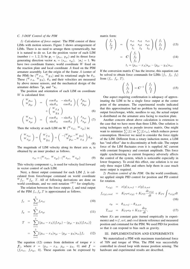
(a) LIM armature (b) Three phase model of windings
Fig. 4. Developed linear induction armature.
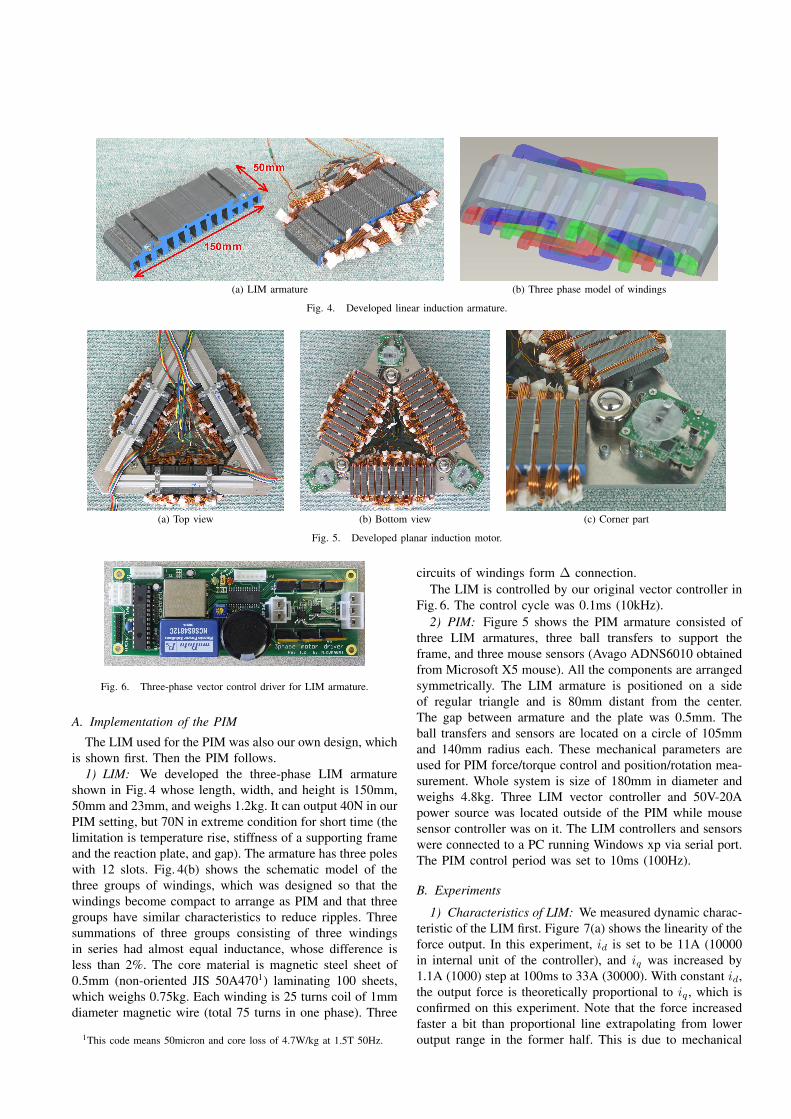
(a) Top view (b) Bottom view (c) Corner part
Fig. 5. Developed planar induction motor.
Fig. 6. Three-phase vector control driver for LIM armature.
A. Implementation of the PIM
The LIM used for the PIM was also our own design, whichis shown first. Then the PIM follows.
1) LIM: We developed the three-phase LIM armatureshown in Fig. 4 whose length, width, and height is 150mm,50mm and 23mm, and weighs 1.2kg. It can output 40N in ourPIM setting, but 70N in extreme condition for short time (thelimitation is temperature rise, stiffness of a supporting frameand the reaction plate, and gap). The armature has three poleswith 12 slots. Fig. 4(b) shows the schematic model of thethree groups of windings, which was designed so that thewindings become compact to arrange as PIM and that threegroups have similar characteristics to reduce ripples. Threesummations of three groups consisting of three windingsin series had almost equal inductance, whose difference isless than 2%. The core material is magnetic steel sheet of0.5mm (non-oriented JIS 50A4701) laminating 100 sheets,which weighs 0.75kg. Each winding is 25 turns coil of 1mmdiameter magnetic wire (total 75 turns in one phase). Three
1This code means 50micron and core loss of 4.7W/kg at 1.5T 50Hz.
circuits of windings form Δ connection.The LIM is controlled by our original vector controller in
Fig. 6. The control cycle was 0.1ms (10kHz).2) PIM: Figure 5 shows the PIM armature consisted of
three LIM armatures, three ball transfers to support theframe, and three mouse sensors (Avago ADNS6010 obtainedfrom Microsoft X5 mouse). All the components are arrangedsymmetrically. The LIM armature is positioned on a sideof regular triangle and is 80mm distant from the center.The gap between armature and the plate was 0.5mm. Theball transfers and sensors are located on a circle of 105mmand 140mm radius each. These mechanical parameters areused for PIM force/torque control and position/rotation mea-surement. Whole system is size of 180mm in diameter andweighs 4.8kg. Three LIM vector controller and 50V-20Apower source was located outside of the PIM while mousesensor controller was on it. The LIM controllers and sensorswere connected to a PC running Windows xp via serial port.The PIM control period was set to 10ms (100Hz).
B. Experiments
1) Characteristics of LIM: We measured dynamic charac-teristic of the LIM first. Figure 7(a) shows the linearity of theforce output. In this experiment, id is set to be 11A (10000in internal unit of the controller), and iq was increased by1.1A (1000) step at 100ms to 33A (30000). With constant id,the output force is theoretically proportional to iq, which isconfirmed on this experiment. Note that the force increasedfaster a bit than proportional line extrapolating from loweroutput range in the former half. This is due to mechanical
0
10
20
30
40
50
0 0.5 1 1.5 2 2.5 3 3.5 4
-30-20-10 0 10 20 30
Thr
ust f
orce
(N
)
Pha
se c
urre
nt (
A)
Time (s)
(a) linearly swept iq (0 to 33A) with constant id (11A)
0
5
10
15
20
25
0 0.5 1 1.5 2 2.5 3
-30
-20
-10
0
10
20
30
Thr
ust f
orce
(N
) Pha
se c
urre
nt (
A)
Time (s)
(b) step response of force output
Fig. 7. Force output of a LIM and three phase currents. Note that thecurrents were saturated at last part of sweep, and that the waveforms of thecurrents were affected by sampling theorem, which degraded the forms.
stiffness that caused decrease of the gap by increase ofattraction force between armature and the back iron plate.Smaller gap generates larger force with the same current.
Figure 7(b) shows dynamic response of the LIM. Before1.6s, the id is kept constant at 10000 and iq is changedthrough 2000, 5000, 10000, and 150000 in the unit at 100msinterval. In the latter part, iq is kept constant at 10000 and idis changed. As mentioned before, id is usually kept constant.In the former half, the force output respond in 10ms withsmall ripple, whereas larger ripple in the latter half especiallythe case decreasing id. These results confirmed that we canachieve 10ms response only by commanding iq.
2) Position and Orientation Control: We confirmed theforce and torque output of the PIM using (15). The trans-lational force could be set independent from the orientationof the PIM. Then we carried out position and orientationtracking control including confirmation of position sensing,force/torque output control.
The reference was designed; the target of center of thePIM was square shaped without interpolation, i.e. the refer-ence jumped to the next point periodically to confirm stepresponse in x and y direction; the reference of rotationalangle is generated by sinusoidal function. Figure 8 showsthe experimental results of the position tracking. Theseexperiments are also included in accompanied video, which
are clearer to check the motion and response. In Fig. 8(a),only the position was set to ±20mm. In (b) the orientationof the PIM is changed in 0.4rad (23◦) amplitude, whichindicated the change of orientation did not affect a lot toposition control. In (a) and (b) the period of the motion was4s, whereas 1s in (c). The rotational amplitude is the samewhile position amplitude was decreased to 10mm. It wasstill under control but the error increased in (c). In the lastcase (d), the reaction plate with the PIM was inclined byhand up to over 60◦. Because the position control employedI control, the gravity term was almost compensated. Notethat a wheeled robot slips down from such a steep slope butthe PIM can generate thrust force not using friction, and alsostick to the surface. In the case (a) to (c), the averaged powerconsumption was approximately 250W, and near 1kW whilemost tilted condition in (d). These results showed usefulnessof our PIM and the method.
IV. CONCLUSIONS
A planar induction motor was developed, and controlmethods using vector control was described in this paper. Thehardware consisted of three linear induction motor armaturesfor actuation, three optical mouse sensors for position andvelocity sensing, and three ball transfers for support. Thevector controller of each LIM had response speed fasterthan 10ms, which enabled good position tracking ability.We achieved closed loop position tracking and measureddynamic response in experiments. At most extreme cases,the speed of the PIM reached 450mm/s in less than 0.1swith peak acceleration of 12m/s2. The PIM armature outputapproximately 60N at that time. Also, the tracking experi-ment was carried out on steep slope of 60◦ inclination, whichresulted in almost same capability. The developed PIM willbe one of probable omnidirectional actuator even thoughit requires reaction plate for operating area. We focus onapplication of the PIM in the next work.
V. ACKNOWLEDGEMENTS
A part of this work was performed in the MicrodynamicSystems Laboratory, The Robotics Institute, Carnegie MellonUniversity, as a part of the dynamically stable mobile robotsproject. It was also supported by KAKENHI(11022515).
REFERENCES
[1] T.B. Lauwers, Z.K. Edmondson, R.L. Hollis, “Free-Roaming PlanarMotors: Toward Autonomous Precision Planar Mobile Robots”, ICRA2004, pp. 4498–4503
[2] J. Pan, N.C. Cheung, J. Yang, “Structure and characteristics of closed-loop two-dimensional surface motors – a literature survey”, proc.Power Electronics and Drive Systems 2003, 2003, pp.236–241
[3] P. Dittrich, D. Radeck, “3-DOF Planar Induction Motor”, proc. Elec-tro/Information Technology 2006, 2006, pp.81–86
[4] N. Fujii, M. Fujitake, “Two-dimensional drive characteristics bycircular-shaped motor”, IEEE trans. Industrial Application, vol.35,no.4, 2002, pp.803-809
[5] M. Kumagai, R.L. Hollis, “Development of a three-dimensional ballrotation sensing system using optical mouse sensors”, ICRA 2011,pp. 5038–5043
[6] M. Kumagai: “Development of a Linear Induction Motor and aVector Control Driver”, SICE tohoku chapter workshop material, 2010,pp. 262–9 (in Japanese language)
-40-30-20-10
0 10 20 30 40
10 11 12 13 14 15 16 17 18 19 20
-30-20-10 0 10 20 30
Pos
ition
(m
m)
Orie
ntat
ion
(deg
ree)
Time (s)
x (ref)y (ref)θ (ref)x (act)y (act)θ (act)
-40
-30
-20
-10
0
10
20
30
40
-40 -30 -20 -10 0 10 20 30 40
Pos
ition
y (
mm
)
Position x (mm)
(act)(ref)
Conditionsposition: ±20mmorientation: 0period: 4s
Notesmax speed: 450mm/smax accel.: 12m/s2
(a) Rectangular motion without rotation
-40-30-20-10
0 10 20 30 40
10 11 12 13 14 15 16 17 18 19 20
-30-20-10 0 10 20 30
Pos
ition
(m
m)
Orie
ntat
ion
(deg
ree)
Time (s)
x (ref)y (ref)θ (ref)x (act)y (act)θ (act)
-40
-30
-20
-10
0
10
20
30
40
-40 -30 -20 -10 0 10 20 30 40
Pos
ition
y (
mm
)
Position x (mm)
(act)(ref)
Conditions:position: ±20mmorientation: ±0.4rad
(±23◦)period: 4s
Notesmax speed: 450mm/smax accel.: 10m/s2
(b) Rectangular motion with rotation
-40-30-20-10
0 10 20 30 40
10 11 12 13 14 15
-30-20-10 0 10 20 30
Pos
ition
(m
m)
Orie
ntat
ion
(deg
ree)
Time (s)
x (ref)y (ref)θ (ref)x (act)y (act)θ (act)
-40
-30
-20
-10
0
10
20
30
40
-40 -30 -20 -10 0 10 20 30 40
Pos
ition
y (
mm
)
Position x (mm)
(act)(ref)
Conditions:position: ±10mmorientation: ±0.4rad
(±23◦)period: 1s
Notesmax speed: 250mm/smax accel.: 8m/s2
(c) Higher frequency motion
-40-30-20-10
0 10 20 30 40
10 15 20 25 30 35 40 45
-20-10 0 10 20
Pos
ition
(m
m)
For
ce c
omm
and
(N)
Time (s)
x (ref)y (ref)x (act)y (act)
f1 (cmd)f2 (cmd)f3 (cmd)
-40
-30
-20
-10
0
10
20
30
40
-40 -30 -20 -10 0 10 20 30 40
Pos
ition
y (
mm
)
Position x (mm)
(act)(ref)
Conditions:position: ±15mmorientation: ±0.4rad
(±23◦)period: 4s
Notesmax tilt: >60◦
(d) Rectangular motion with rotation while tilting the plate about x axis (gravity acts on y direction)
Fig. 8. Time responses and geometrical plots of PIM in four conditions. ‘(ref)’, ‘(act)’ and ‘(cmd)’ mean reference value, measured actual value, andcommanded value. Maximum speed and acceleration is typical value measured from the data.


![Mechanism design for parallel manipulators robot, Delta; Gosselin and Angeles studied a planar 3-DOF parallel manipulator [3] that possesses 8-bar linkages with 2 ternary links connected](https://static.documents.pub/doc/80x56/5b006e0e7f8b9a952f8ce30b/mechanism-design-for-parallel-robot-delta-gosselin-and-angeles-studied-a-planar.jpg)


