Development and Field Testing Novel Natural Gas (NG) Surface Process Equipment for Replacement of Water as Primary Hydraulic Fracturing Fluid Griffin Beck Southwest Research Institute (PI) U.S. Department of Energy National Energy Technology Laboratory Mastering the Subsurface Through Technology Innovation, Partnerships and Collaboration: Carbon Storage and Oil and Natural Gas Technologies Review Meeting August 1-3, 2017 Project # DE-FE0024314
Transcript
Development and Field Testing Novel Natural Gas (NG) Surface Process Equipment for Replacement
of Water as Primary Hydraulic Fracturing Fluid
Griffin BeckSouthwest Research Institute (PI)
U.S. Department of EnergyNational Energy Technology Laboratory
Mastering the Subsurface Through Technology Innovation, Partnerships and Collaboration:Carbon Storage and Oil and Natural Gas Technologies Review Meeting
August 1-3, 2017
Project # DE-FE0024314
This presentation provides an overview of a recent laboratory investigation of natural-gas based foams
2
1. NG foam fracturing project overview2. Summary of project findings to date3. Description of test facility and
objectives4. Summary of results5. Future work
Pilot Scale Foam Test Facility
1. Gallegos, T. J., et al., “Hydraulic Fracturing Water Use Variability in the United States and Potential Environmental Implications,” Water Resources Research, 51 (7) pp. 5839-5845, (July 2015).
• Water is used to initiate fracture and carry proppant.
• As much as 9.7 million gal/well1
• Significant transportation required
• Recovered water must be either cleaned or disposed.
Shale Gas Formations1. Barnett2. Eagle Ford3. Woodford4. Fayetteville5. Haynesville-Bossier6. Tuscaloosa7. Marcellus and Utica
Typical hydraulic fracture treatments require a significant volume of water
SwRI and SLB are developing a novel process that uses of natural gas as the primary fracturing fluid
Current Fracturing Process
• The proposed process uses NG foam for hydraulic fracture treatment.• This could reduce water consumption by as much as 80%.• Natural gas is readily available at well site.• The recovered natural gas would be processed.
Proposed Natural Gas Fracturing Process
Gas/Water/Proppant
MixingProppant Supply
Well InjectionNatural Gas
Compression of Natural Gas
Water Supply
5
Initial work identified an appropriate surface process and reviewed foam rheology literature
• Six processes (including compression and liquefaction cycles) were analyzed.
• The optimal process to produce high pressure NG is through direct compression.
• Equipment needed to compress gas is commercially available.
Key Findings from Process Development2-4
Direct Compression Process
2. Verma, S., et al., “Novel Fracturing Process Utilizing Natural Gas,” presented at the AIChE Annual Meeting, San Francisco, CA (November 13-18, 2016).
3. Beck, G. and Verma, S., “Development and Field Testing Novel Natural Gas (NG) Surface Process Equipment for Replacement of Water as Primary Hydraulic Fracturing Fluid,” presented at the 2016 Carbon Storage and Oil and Natural Gas Technologies Review Meeting, Pittsburgh, PA (August 16-18, 2016).
4. Beck, G., et. al. “Development and Evaluation of a Mobile Plant to Prepare Natural Gas for Use in Foam Fracturing Treatments,” presented at the 2017 ASME Turbo Expo, Charlotte, NC (June 26-30, 2017).
• No published data for NG foam rheology is available.
• Summary of CO2 and N2 foam trends observed in literature:‒ Fluid viscosity changes with foam
quality (𝑥𝑥).‒ Temperature impacts viscosity
(increasing T decreases µ).‒ Bubble size has minimal impact on
foam viscosity.‒ Pressure has a small effect on foam
viscosity.‒ Foam viscosity is dominated by
foam quality and base fluid viscosity.
• NG foam is expected to follow CO2and N2 foam trends.
Key Findings from Literature Review2
𝑥𝑥 % =�̇�𝑄𝑔𝑔𝑔𝑔𝑔𝑔
�̇�𝑄𝑔𝑔𝑎𝑎𝑎𝑎 + �̇�𝑄𝑔𝑔𝑔𝑔𝑔𝑔× 100
BP2 work focused on constructing & operating a test facility to generate high pressure NG foam
6P&ID of BP2 Pilot Scale Test Facility
• Generate rheology data• NG foam rheology data not
publically available• Critical for reservoir
simulations, system simulations, and others
Goal 1: NG Foam Rheology
• NG should be dispersed uniformly in base fluid
• Requires appropriate fluid chemistry AND mixing method
Goal 2: Evaluate Foam Mixing
• Pressure transients can impact compression equipment
• Compressibility of gas and aqueous phase is well known, foam compressibility is unknown
Goal 3: Pressure Transient
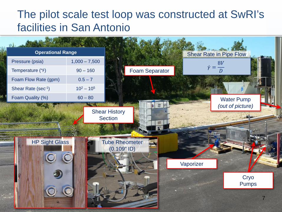
The pilot scale test loop was constructed at SwRI’sfacilities in San Antonio
7
Operational Range
Pressure (psia) 1,000 – 7,500
Temperature (°F) 90 – 160
Foam Flow Rate (gpm) 0.5 – 7
Shear Rate (sec-1) 102 – 105
Foam Quality (%) 60 – 80
Foam Separator
CryoPumps
Vaporizer
Water Pump(out of picture)
HP Sight Glass Tube Rheometer (0.109” ID)
Shear History Section
�̇�𝛾 =8𝑉𝑉𝐷𝐷
Shear Rate in Pipe Flow
Two mixing methods yield observable differences in mixture quality
8
Mixture of Water/Methane filter in place
no guar or surfactant
NG Foamfilter in placelarge ID tube
NG Foamno filter
large ID tube
• Stable foam was generated up to 4750 psia.
• 100 µm filter appears to promote a better mixture.
• More work is needed to investigate foam mixing and stability.Base Fluid
Stream
Methane Stream
FoamStream
100 µm Filter • Two mixing methods:‒ Simple tee ‒ 100 µm filter downstream of tee
1”
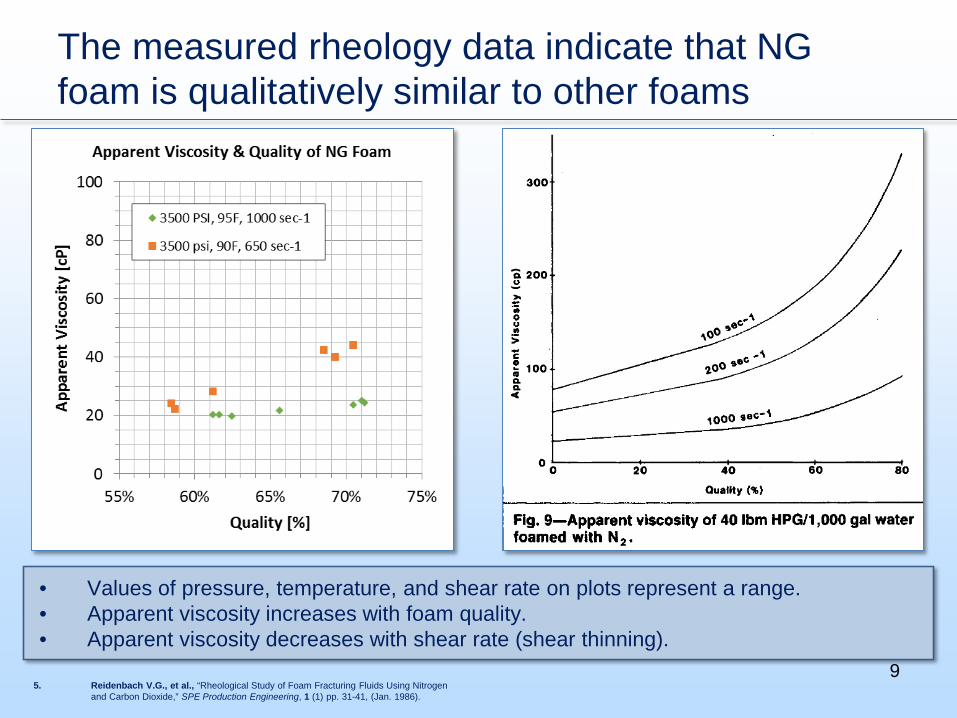
The measured rheology data indicate that NG foam is qualitatively similar to other foams
9
• Values of pressure, temperature, and shear rate on plots represent a range. • Apparent viscosity increases with foam quality.• Apparent viscosity decreases with shear rate (shear thinning).
5. Reidenbach V.G., et al., “Rheological Study of Foam Fracturing Fluids Using Nitrogen and Carbon Dioxide,” SPE Production Engineering, 1 (1) pp. 31-41, (Jan. 1986).
NG foams appear to share other similarities to published data
10
• Foam rheology in laminar regime often described as either a Herschel-Bulkley5 or a power lawfluid.6-8
• Based on limited data, it seems reasonable to describe NG foam as a power law fluid.
• More definitive models and/or correlations will require a larger experimental data set.
5. Reidenbach V.G., et al., “Rheological Study of Foam Fracturing Fluids Using Nitrogen and Carbon Dioxide,” SPE Production Engineering, 1 (1) pp. 31-41, (Jan. 1986).
6. Wendorff, C.L. and Earl, R.B., “Foam Fracturing Laboratory,” presented at the 58th Annual Technical Conference and Exhibition, San Francisco, CA, (Oct. 5-8, 1983)
7. Cawiezel, K.E. and Niles, T. D., “Rheological Properties of Foam Fracturing Fluids Under Downhole Conditions,” presented at the SPE Production Operations Symposium, Oklahoma City, OK (Mar. 8-10,1987)
8. Hutchins, R.D., et al., “A Circulating Foam Loop for Evaluating Foam at Conditions of Use,” presented at the SPE International Symposium on Oilfield Chemistry, Houston, TX (Feb. 5-7, 2003)
𝜏𝜏 = 𝜏𝜏0 + 𝐾𝐾�̇�𝛾𝑛𝑛 𝜏𝜏 = 𝐾𝐾�̇�𝛾𝑛𝑛
Herschel-Bulkley Power Law
Data collected at higher shear rates appears to be in the turbulent flow regime
11
• Published data5 (N2 foam data shown) indicate that, for a given tube size, the data all collapse to a single curve regardless of quality in the turbulent regime.
• A similar trend is observed from the small tube data.
5. Reidenbach V.G., et al., “Rheological Study of Foam Fracturing Fluids Using Nitrogen and Carbon Dioxide,” SPE Production Engineering, 1 (1) pp. 31-41, (Jan. 1986).
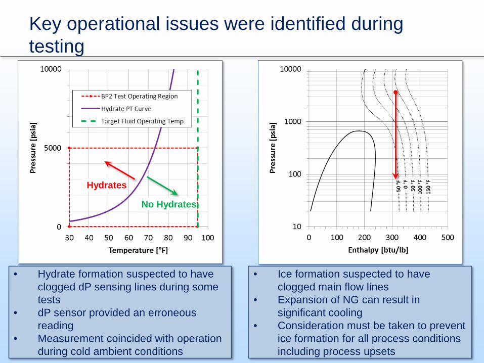
Key operational issues were identified during testing
12
• Hydrate formation suspected to have clogged dP sensing lines during some tests
• dP sensor provided an erroneous reading
• Measurement coincided with operation during cold ambient conditions
• Ice formation suspected to have clogged main flow lines
• Expansion of NG can result in significant cooling
• Consideration must be taken to prevent ice formation for all process conditions including process upsets
No Hydrates
Hydrates
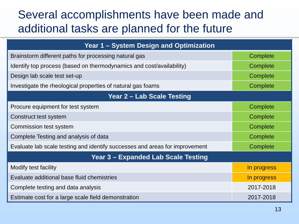
Several accomplishments have been made and additional tasks are planned for the future
13
Year 1 – System Design and OptimizationBrainstorm different paths for processing natural gas Complete
Identify top process (based on thermodynamics and cost/availability) Complete
Design lab scale test set-up Complete
Investigate the rheological properties of natural gas foams Complete
Year 2 – Lab Scale TestingProcure equipment for test system Complete
Construct test system Complete
Commission test system Complete
Complete Testing and analysis of data Complete
Evaluate lab scale testing and identify successes and areas for improvement Complete
Year 3 – Expanded Lab Scale TestingModify test facility In progress
Evaluate additional base fluid chemistries In progress
Complete testing and data analysis 2017-2018
Estimate cost for a large scale field demonstration 2017-2018
There are opportunities for collaboration between projects
14
• Lab-scale test stand can be used to investigate a variety of foams and other fracturing fluids at field conditions.
• Current and future investigations can utilize the facility at SwRI
Foam/Fracture Fluid Test Stand
• Use of natural gas as a fracturing fluid could enhance recovery• Present and future research of enhanced recovery using natural gas can
be leveraged to improve the NG foam fracturing methods investigated by the current project
Enhanced Oil Recovery (EOR)
• Limited NG foam rheology data published• Foam rheology results from current work can be used in multiple
simulation codes
Foam Fluid Data
At the conclusion of BP2, the test goals were achieved and several important insights were gained
15
• Pilot scale facility was designed, built, and operated.
• Stable NG foam was generated at 4750 psi using a commercially available viscosifier and surfactant.
• Two mixing methods were explored and key differences were observed.
• NG foam is qualitatively similar to other foams.‒ Shear thinning, power law fluid‒ Increased viscosity with foam quality‒ Laminar and turbulent regimes
• Transient pressure data was generated.• Key operational issues identified.
‒ With NG, hydrate formation can occur‒ Considerations must be taken to
prevent ice formation
Key Findings from Year 2• Modify the existing pilot scale facility to
enhance measurement capability.• Evaluate additional base fluid chemistries
for compatibility with NG foam.• Generate a larger experimental data set to
fully characterize NG foam rheology.• Identify appropriate foam mixing methods
1. Beck, G. and Verma, S., “Development and Field Testing Novel Natural Gas (NG) Surface Process Equipment for Replacement of Water as Primary Hydraulic Fracturing Fluid,” presented at the 2016 Carbon Storage and Oil and Natural Gas Technologies Review Meeting, Pittsburgh, PA (August 16-18, 2016).
2. Verma, S., et al., “Novel Fracturing Process Utilizing Natural Gas,” presented at the AIChE Annual Meeting, San Francisco, CA (November 13-18, 2016).
3. Beck, G., et. al., “Laboratory Evaluation of a Natural Gas-Based Foamed Fracturing Fluid,” presented at the 2017 AIChE Spring Meeting, San Antonio, TX (March 26-30, 2017)
4. Beck, G., et. al., “Development and Evaluation of a Mobile Plant to Prepare Natural Gas for Use in Foam Fracturing Treatments,” presented at the 2017 ASME Turbo Expo, Charlotte, NC (June 26-30, 2017).
20
References
1. Gallegos, T. J., et al., “Hydraulic Fracturing Water Use Variability in the United States and Potential Environmental Implications,” Water Resources Research, 51 (7) pp. 5839-5845, (July 2015).
2. Verma, S., et al., “Novel Fracturing Process Utilizing Natural Gas,” presented at the AIChE Annual Meeting, San Francisco, CA (November 13-18, 2016).
3. Beck, G. and Verma, S., “Development and Field Testing Novel Natural Gas (NG) Surface Process Equipment for Replacement of Water as Primary Hydraulic Fracturing Fluid,” presented at the 2016 Carbon Storage and Oil and Natural Gas Technologies Review Meeting, Pittsburgh, PA (August 16-18, 2016).
4. Beck, G., et. al., “Development and Evaluation of a Mobile Plant to Prepare Natural Gas for Use in Foam Fracturing Treatments,” presented at the 2017 ASME Turbo Expo, Charlotte, NC (June 26-30, 2017).
5. Reidenbach V.G., et al., “Rheological Study of Foam Fracturing Fluids Using Nitrogen and Carbon Dioxide,” SPE Production Engineering, 1 (1) pp. 31-41, (Jan. 1986).
6. Wendorff, C.L. and Earl, R.B., “Foam Fracturing Laboratory,” presented at the 58th Annual Technical Conference and Exhibition, San Francisco, CA, (Oct. 5-8, 1983)
7. Cawiezel, K.E. and Niles, T. D., “Rheological Properties of Foam Fracturing Fluids Under Downhole Conditions,” presented at the SPE Production Operations Symposium, Oklahoma City, OK (Mar. 8-10,1987)
8. Hutchins, R.D., et al., “A Circulating Foam Loop for Evaluating Foam at Conditions of Use,” presented at the SPE International Symposium on Oilfield Chemistry, Houston, TX (Feb. 5-7, 2003)
9. Nolen-Hoeksema, R., “Elements of Hydraulic Fracturing,” Oilfield Review, 25 (2) pp. 51-52, (2013)