DEVELOPMENT OF A 1 MWE SUPERCRITICAL CO 2 BRAYTON CYCLE TEST LOOP The 4th International Symposium - Supercritical CO 2 Power Cycles September 9-10, 2014, Pittsburgh, Pennsylvania Jeff Moore, Ph.D. Klaus Brun, Ph.D. Neal Evans Pablo Bueno, Ph.D. C.J. Kalra, Ph.D. SwRI SwRI SwRI SwRI GE GRC
Transcript
DEVELOPMENT OF A 1 MWE SUPERCRITICAL
CO2 BRAYTON CYCLE TEST LOOP
The 4th International Symposium - Supercritical CO2 Power Cycles September 9-10, 2014, Pittsburgh, Pennsylvania
Jeff Moore, Ph.D. Klaus Brun, Ph.D. Neal Evans Pablo Bueno, Ph.D. C.J. Kalra, Ph.D. SwRI SwRI SwRI SwRI GE GRC
Acknowledgements: Richard Carlson Lalit Chordia Thar Energy Patrick Fourspring Ken Kimball Joseph McDonald Brian Morris Bechtel Marine
2
Mark Lausten Levi Irwin U.S. Dept. of Energy
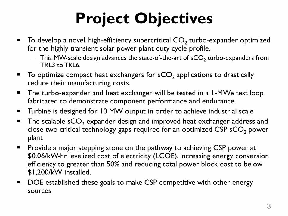
Project Objectives To develop a novel, high-efficiency supercritical CO2 turbo-expander optimized
for the highly transient solar power plant duty cycle profile. – This MW-scale design advances the state-of-the-art of sCO2 turbo-expanders from
TRL3 to TRL6. To optimize compact heat exchangers for sCO2 applications to drastically
reduce their manufacturing costs. The turbo-expander and heat exchanger will be tested in a 1-MWe test loop
fabricated to demonstrate component performance and endurance. Turbine is designed for 10 MW output in order to achieve industrial scale The scalable sCO2 expander design and improved heat exchanger address and
close two critical technology gaps required for an optimized CSP sCO2 power plant
Provide a major stepping stone on the pathway to achieving CSP power at $0.06/kW-hr levelized cost of electricity (LCOE), increasing energy conversion efficiency to greater than 50% and reducing total power block cost to below $1,200/kW installed.
DOE established these goals to make CSP competitive with other energy sources
3
Work has been divided into three phases that emulate development process from TRL3 to TRL6 Phase I – Turbomachinery, HX, and flow loop
design (22 months) Phase II – Component fabrication and test
loop commissioning (12 months) Phase III – Performance and endurance testing
(6 months)
Project Approach
4
DOE selected 1-MWe test loop size which offers balance between cost and benefit
The test loop layout has been designed with the intent of minimizing thermal stress, and maximizing use of existing infrastructure
Loop piping and components will make use of the recently completed Turbomachinery Research Facility at SwRI
The test loop is designed around the main and supporting components: expander, heater, pump, compressor, cooler, and dyno – Custom engineered air dynamometer will absorb the power
produced by the expander during testing
Test Loop Layout and Integration
5
The Sunshot program is funded by the Department of Energy (DOE) Office of Energy Efficiency and Renewable Energy (EERE) SunShot office under the CSP power block Funding Opportunity Announcement (FOA).
Co-funding is provided by our partners General Electric, Thar Energy, and Bechtel Marine.
The thermal-to-electric efficiency of current CSP plants is 35 to 45% (DOE, 2012).
The goal of this program is to meet these aggressive performance and cost goals: – Net cycle efficiency > 50% – Dry cooled – Cost < $1,200/kWe
Sunshot Goals
Southwest Research Institute (SwRI) in collaboration with General Electric and Thar Energy was awarded a Phase I award on the design and development of these tasks:
Design Supercritical CO2 Brayton Cycle Power block to achieve FOA goals
Proposed modular power block in 10 MWe range to meet CAPEX targets
Compact power block for pre-fabricated tower mounted operation SwRI scope includes test loop design and operation, assist GE with
expander engineering, manufacturing drawings, and expander fabrication.
GE is responsible for the power block design, thermo-economic analysis, and test loop cycle design.
GE to design the sCO2 turbo-generator to meet FOA targets. Thar Energy to design recuperator for the power block meeting the
FOA efficiency and cost targets. – 30% reduction in recuperator cost from current state-of-the-art
Project Work Breakdown
Project Work Breakdown Schedule
22 months 12 months 6 months
Phase 9/12 – 7/14
Phase 2 8/14 – 8/15
Phase 3 8/15 – 2/16
• Test loop design & component/vendor
identification (1 MWe)
• Test loop fabrication • Expander assembly and shake-down testing Expander testing
Cooling water bypass TV-01 Existing 3-way cooling water bypass hand valve Flow meter ORF Orifice plate flow meter
V-cone V-CONE Flow meter Strainer STR 4” Y-strainer
Relief valve PSV-01 Set pressure = 4000 psig Relief valve PSV-02 Set pressure = 4000 psig Relief valve PSV-03 Set pressure = 1975 psig Relief valve PSV-04 Existing 2x3”, set pressure = 1975 psig
Test Loop Process and Instrumentation Diagram
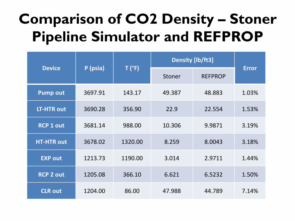
Comparison of CO2 Density – Stoner Pipeline Simulator and REFPROP
Device P (psia) T (°F) Density [lb/ft3]
Error Stoner REFPROP
Pump out 3697.91 143.17 49.387 48.883 1.03%
LT-HTR out 3690.28 356.90 22.9 22.554 1.53%
RCP 1 out 3681.14 988.00 10.306 9.9871 3.19%
HT-HTR out 3678.02 1320.00 8.259 8.0043 3.18%
EXP out 1213.73 1190.00 3.014 2.9711 1.44%
RCP 2 out 1205.08 366.10 6.621 6.5232 1.50%
CLR out 1204.00 86.00 47.988 44.789 7.14%
Predicted Nozzle Loads
Fx (lb) Fy Fz Mx (ft-lb) My Mz RCP-C in 66 -50 -120 -144.3 -130.8 -89
RCP-H out 74 -305 -129 456.2 48.7 -185.4 HTR in 17 -92 -85 143.4 290.4 -253.4
HTR out 305 605 -252 -325.4 1166.5 490.7 EXP in, top 670 -143 -143 -105.6 -457 -777.2
EXP in, bottom -365 -149 -109 53.1 -393.1 -477.7 EXP out, top 333 898 -170 -1613.1 175.1 164.8
EXP out, bottom 102 -781 -82 1414.5 121.9 -618.3 RCP-H in, top 232 -2537 101 2405 -386.2 287.4
RCP-H in, bottom 118 2271 -94 -2334.2 -292.2 -522.7 RCP-C out 55 169 165 195.3 -686.6 457.4
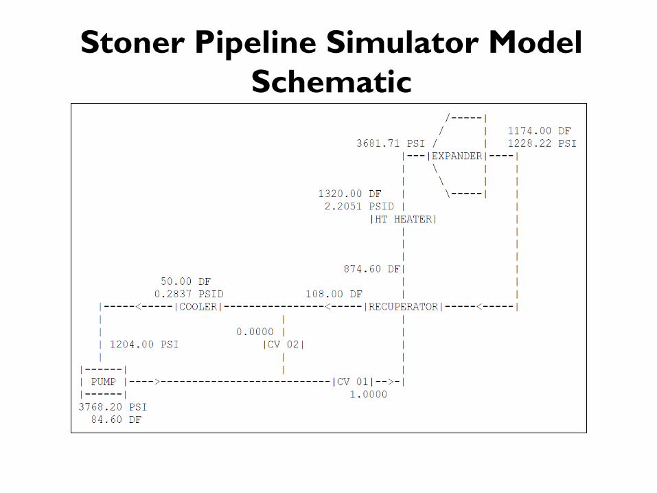
Stoner Pipeline Simulator Model Schematic
Existing Facility Piping and Expander Piping
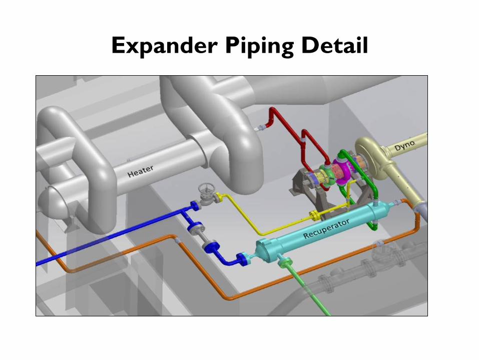
Expander Piping Detail
Existing 3 MW CO2 Compressor
Existing CO2 Pipe Loop
Conclusions • Design of a high-pressure, high-temperature SCO2 flow loop has
been completed to measure the mechanical and flow performance of a custom SCO2 turbine expander and recuperator.
• The flow capacity of the loop is equivalent to a 1 MWe size. • Test loop provides a platform to perform mechanical and
performance testing of the expander and recuperator. • The test loop design has sized the pipe to maintain acceptable flow
velocities and pressure drop. • A thermal piping analysis was performed to demonstrate
acceptable pipe loading on the expander and recuperator nozzles. • All of the test loop design objectives were satisfied. • Manufacturing will commence in Phase 2 of the program.