Developments in Radiographic Inspection Methods Development of a Digital Radiographic System for Power Plant Components S.M. Walker, Electric Power Research Institute, USA ABSTRACT Corrosion-fatigue, a cracking mechanism in fossil-fueled generating plants, predominately occurs in the water walls and economizers of sub-critical plants. Cracking attributed to corrosion-fatigue has occurred in water wall tubing of both membrane and tangential designs. The occurrence (particularly in membrane water wall tubing) presents a challenge for nondestructive evaluation (NDE) because the mechanism manifests itself as multiple cracks which initiate and grow on the inside surface of the tubes on the casing side of the tubes, locations which are not typically accessible for conventional NDE techniques. To address detection of such cracking, EPRI is developing a radiographic system based on complementary metal oxide semiconductor (CMOS) technology. The system includes a CMOS real-time digital detector, portable X-Ray device, data acquisition and display software, and remotely operated robotic devices for positioning the X-Ray device and the detector throughout the boiler regions susceptible to corrosion- fatigue cracking. The capabilities of the CMOS system for detection of corrosion-fatigue cracking in boiler water wall tubing are discussed in this paper. INTRODUCTION Radiographic examination information can be acquired using conventional film, phosphor plate radiography, or direct digital detectors as the radiographic imaging media. Phosphor plate radiography has been available as an examination technique for power plants for over a decade. An EPRI study in 1997 showed that the available phosphor plate equipment at the time was effective for a range of utility applications and could be utilized while further refinements were underway. Direct digital detectors have also been available for a number of years, but the emphasis has historically been on detection of wall thinning mechanisms, rather than cracking because of the resolution being directly correlated to detector element size. EPRI collaborated with the petrochemical industry in order to assemble a direct digital detector radiographic system in 1998 for detection of wall thinning in pipe. Recently, improvements in technology have evolved to the point where digital detector sizes have become quite small and adequate resolution is achieved to detect cracking. DIRECT DIGITAL DETECTORS Available direct-digital radiographic detectors are developing and rapidly improving. The ability to perform real-time, or near real-time, radiography provides many benefits to the utility industry: • Significant increase in examination speed since film does not have to be placed, removed and processed • Remote delivery of examination equipment, reducing radiation exposure to personnel • Potentially performing examination while the plant is on-line • The ability to move the detector in order to obtain a better understanding of component geometry and flaw orientation • The ability to re-align the source and detector orientation with the flaw plane to improve flaw detection and evaluation For more papers of this publication click: www.ndt.net/search/docs.php3?MainSource=70 6th International Conference on NDE in Relation to Structural Integrity for Nuclear and Pressurized Components October 2007, Budapest, Hungary
Transcript
Developments in Radiographic Inspection Methods
Development of a Digital Radiographic System for Power Plant Components S.M. Walker, Electric Power Research Institute, USA
ABSTRACT
Corrosion-fatigue, a cracking mechanism in fossil-fueled generating plants, predominately occurs in the
water walls and economizers of sub-critical plants. Cracking attributed to corrosion-fatigue has occurred
in water wall tubing of both membrane and tangential designs. The occurrence (particularly in membrane
water wall tubing) presents a challenge for nondestructive evaluation (NDE) because the mechanism
manifests itself as multiple cracks which initiate and grow on the inside surface of the tubes on the casing
side of the tubes, locations which are not typically accessible for conventional NDE techniques. To
address detection of such cracking, EPRI is developing a radiographic system based on complementary
metal oxide semiconductor (CMOS) technology. The system includes a CMOS real-time digital detector,
portable X-Ray device, data acquisition and display software, and remotely operated robotic devices for
positioning the X-Ray device and the detector throughout the boiler regions susceptible to corrosion-
fatigue cracking. The capabilities of the CMOS system for detection of corrosion-fatigue cracking in
boiler water wall tubing are discussed in this paper.
INTRODUCTION
Radiographic examination information can be acquired using conventional film, phosphor plate
radiography, or direct digital detectors as the radiographic imaging media. Phosphor plate radiography
has been available as an examination technique for power plants for over a decade. An EPRI study in
1997 showed that the available phosphor plate equipment at the time was effective for a range of utility
applications and could be utilized while further refinements were underway.
Direct digital detectors have also been available for a number of years, but the emphasis has
historically been on detection of wall thinning mechanisms, rather than cracking because of the resolution
being directly correlated to detector element size. EPRI collaborated with the petrochemical industry in
order to assemble a direct digital detector radiographic system in 1998 for detection of wall thinning in
pipe. Recently, improvements in technology have evolved to the point where digital detector sizes have
become quite small and adequate resolution is achieved to detect cracking.
DIRECT DIGITAL DETECTORS
Available direct-digital radiographic detectors are developing and rapidly improving. The ability to
perform real-time, or near real-time, radiography provides many benefits to the utility industry:
• Significant increase in examination speed since film does not have to be placed, removed and
processed
• Remote delivery of examination equipment, reducing radiation exposure to personnel
• Potentially performing examination while the plant is on-line
• The ability to move the detector in order to obtain a better understanding of component geometry
and flaw orientation
• The ability to re-align the source and detector orientation with the flaw plane to improve flaw
detection and evaluation
For more papers of this publication click: www.ndt.net/search/docs.php3?MainSource=70
6th International Conference on NDE in Relation to Structural Integrity for Nuclear and Pressurized ComponentsOctober 2007, Budapest, Hungary
• Scanning of a component to allow compilation of three-dimensional tomographic images for defect
characterization and sizing
To implement the technology and take advantage of these benefits, the overall system capability
must be appropriate for the component and the type of defect of interest. For power plant applications, the
capability and limitations of the technology should also be demonstrated such that false assumptions on
probability of detection do not occur.
Many different types of direct-digital detectors exist, but in order to be accepted for use in the
power (and most other industries), the capability of the detectors must be well-understood. Quantifying
the capability of film radiography took decades, even though there were significantly fewer variables with
film than there are with the digital detectors. While there were different film manufacturers and
differences between films, film types were relatively standardized and classified such that comparisons
could readily be made. Digital detectors, on the other hand, can be significantly different from one
another. Additionally, with the addition of electronics in both image capture and image display, the
number of variables is much greater than that of a film radiographic process.
As a result, evaluating the performance of the various systems on a single application (component)
could take a considerable amount of time. Conversely, to develop an understanding of performance of
even a single system so that its capability could be predicted on a variety of components would also be a
significant effort. The effort becomes even more complex when using each type of detector in
combination with many different radiographic sources is considered.
Since the performance of digital detectors is quite different from conventional radiographic film
(greater sensitivity, increased dynamic range), it is difficult to utilize past experiences in order to draw
comparisons about digital radiographic performance on a given component. Even if such comparisons
could be defined, there is very little experimental information available on the performance of film
radiography. Even requirements of the ASME code are based on experience and expert opinion that has
been collected over many decades and not well-documented.
BOILER TUBE CORROSION-FATIGUE
Cracking due to corrosion-fatigue typically occurs on the inside surface of the tube on the tube side that is
opposite the boiler firebox. This location is at the exterior of the boiler and typically has limited access
due to the presence of insulation, building structural components and the exterior building covering.
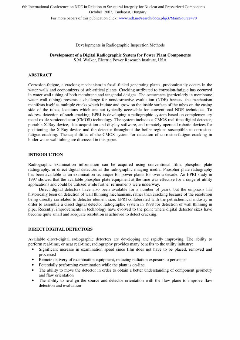
A typical location that may experience corrosion-fatigue is shown in Figure 1. Note the presence of
the scallop bar and casing structure which presents a limitation to conventional NDE, either ultrasonic or
radiographic. The outer building structure is further from the water wall tubes and not shown in Figure 1.
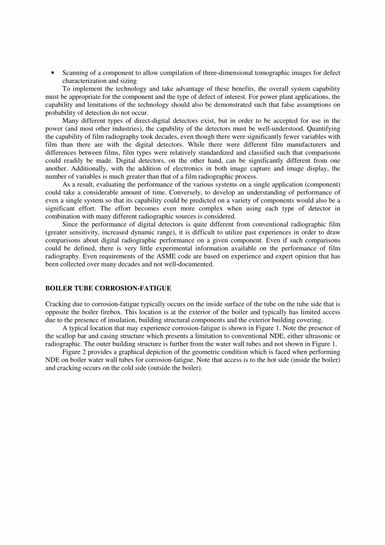
Figure 2 provides a graphical depiction of the geometric condition which is faced when performing
NDE on boiler water wall tubes for corrosion-fatigue. Note that access is to the hot side (inside the boiler)
and cracking occurs on the cold side (outside the boiler).
Figure 1 - Location of Corrosion-Fatigue Failures on Boiler Water Wall Tubes
Hot Side – Inside Boiler
Cold Side –
Access Limited (Lagging, insulation, etc.)
Figure 2 -Corrosion-Fatigue Crack Locations on Boiler Water wall Tubing
EVALUATION OF DIGITAL RADIOGRAPHY FOR CORROSION-FATIGUE CRACK
DETECTION
In the search for techniques to identify water wall corrosion-fatigue cracking, potential applications for
digital radiography were evaluated to detect cracks on the inaccessible wall of boiler tubes. Using a state-
of-the-art system from Envision Product Design LLC, axial corrosion-fatigue cracking on the inner
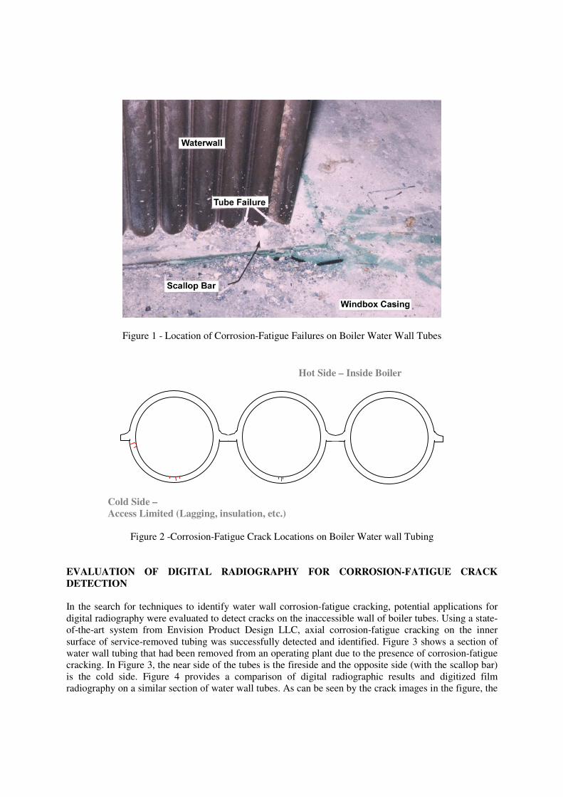
surface of service-removed tubing was successfully detected and identified. Figure 3 shows a section of
water wall tubing that had been removed from an operating plant due to the presence of corrosion-fatigue
cracking. In Figure 3, the near side of the tubes is the fireside and the opposite side (with the scallop bar)
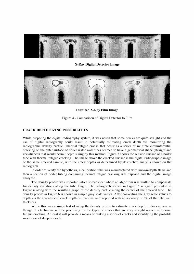
is the cold side. Figure 4 provides a comparison of digital radiographic results and digitized film
radiography on a similar section of water wall tubes. As can be seen by the crack images in the figure, the
digital radiography is at least as sensitive as conventional film radiography, which has long been accepted
as a valid NDE method for crack detection.
Water wall corrosion-fatigue has presented an examination problem to plants because access is
from inside the boiler at the fireside of the water wall tubes, but the cracking initiates on the inside surface
of the back (or cold side) of the tubes which is inaccessible. Ultrasonic examination has not yet been
successfully applied to detect this type of cracking from the fireside of the boiler water wall tubes. This
fortuitous finding immediately prompted plans for a project that will team the system’s compact,
lightweight and rugged digital detector with two motorized scanners for boiler water wall examinations.
These examinations will require synchronization of the motion for the real-time, direct-digital detector
with the motion for the system’s X-ray or gamma-ray source.
Figure 3 - Photograph of Field-Removed Boiler Water Wall Tubes
SYSTEM DESIGN
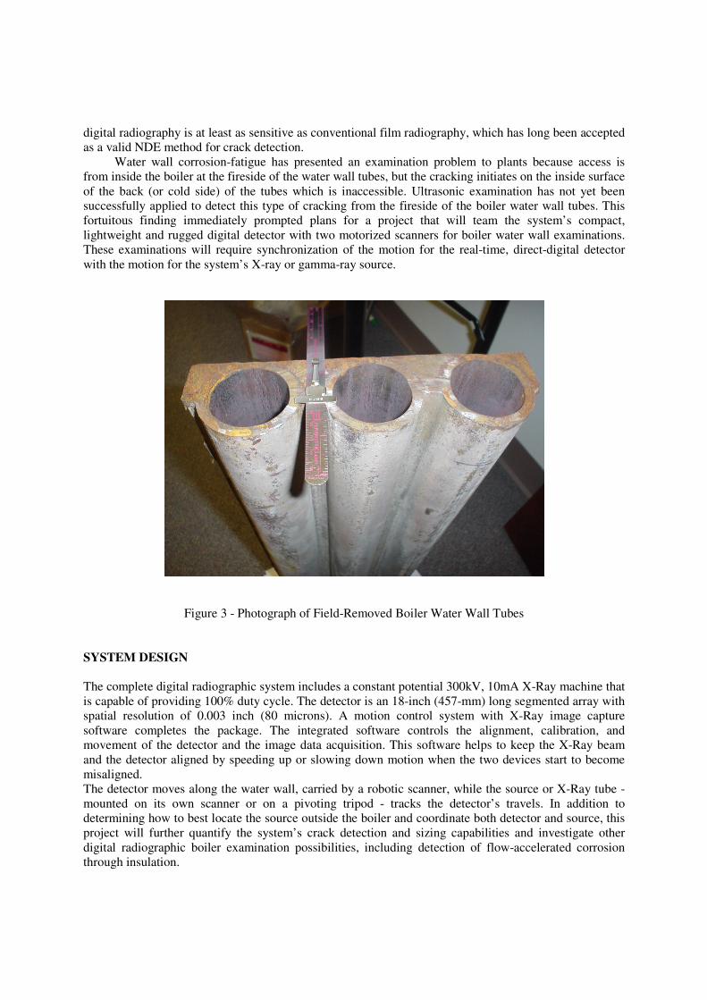
The complete digital radiographic system includes a constant potential 300kV, 10mA X-Ray machine that
is capable of providing 100% duty cycle. The detector is an 18-inch (457-mm) long segmented array with
spatial resolution of 0.003 inch (80 microns). A motion control system with X-Ray image capture
software completes the package. The integrated software controls the alignment, calibration, and
movement of the detector and the image data acquisition. This software helps to keep the X-Ray beam
and the detector aligned by speeding up or slowing down motion when the two devices start to become
misaligned.
The detector moves along the water wall, carried by a robotic scanner, while the source or X-Ray tube -
mounted on its own scanner or on a pivoting tripod - tracks the detector’s travels. In addition to
determining how to best locate the source outside the boiler and coordinate both detector and source, this
project will further quantify the system’s crack detection and sizing capabilities and investigate other
digital radiographic boiler examination possibilities, including detection of flow-accelerated corrosion
through insulation.
X-Ray Digital Detector Image
Digitized X-Ray Film Image
Figure 4 - Comparison of Digital Detector to Film
CRACK DEPTH SIZING POSSIBILITIES
While preparing the digital radiography system, it was noted that some cracks are quite straight and the
use of digital radiography could result in potentially estimating crack depth via monitoring the
radiographic density profile. Thermal fatigue cracks that occur as a series of multiple circumferential
cracking on the outer surface of boiler water wall tubes seemed to have a geometrical shape (straight and
vee-shaped) that would permit depth sizing by this method. Figure 5 shows the outside surface of a boiler
tube with thermal fatigue cracking. The image above the cracked surface is the digital radiographic image
of the same cracked sample, with the crack depths as determined by destructive analysis shown on the
radiograph.
In order to verify the hypothesis, a calibration tube was manufactured with known-depth flaws and
then a section of boiler tubing containing thermal fatigue cracking was exposed and the digital image
analyzed.
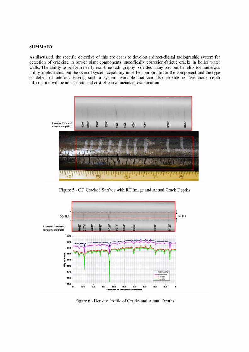
The density profile was imported into a spreadsheet where an algorithm was written to compensate
for density variations along the tube length. The radiograph shown in Figure 5 is again presented in
Figure 6 along with the resulting graph of the density profile along the center of the cracked tube. The
density profile in Figure 6 is shown in simple gray scale values. After converting the gray scale values to
depth via the spreadsheet, crack depth estimations were reported with an accuracy of 5% of the tube wall
thickness.
While this was a single test of using the density profile to estimate crack depth, it does appear as
though this technique will be promising for the types of cracks that are very straight – such as thermal
fatigue cracking. At least it will provide a means of ranking a series of cracks and identifying the probable
worst case of deepest crack.
SUMMARY
As discussed, the specific objective of this project is to develop a direct-digital radiographic system for
detection of cracking in power plant components, specifically corrosion-fatigue cracks in boiler water
walls. The ability to perform nearly real-time radiography provides many obvious benefits for numerous
utility applications, but the overall system capability must be appropriate for the component and the type
of defect of interest. Having such a system available that can also provide relative crack depth
information will be an accurate and cost-effective means of examination.
Figure 5 - OD Cracked Surface with RT Image and Actual Crack Depths
Figure 6 - Density Profile of Cracks and Actual Depths