Development of a Mixed-Refrigerant Joule-Thomson Microcryocooler P.E. Bradley 1 , R. Radebaugh 1 , M. Huber 1 , M.-H.Lin 2 , and Y.C. Lee 2 1 National Institute of Standards and Technology, Boulder, Colorado 80305 2 University of Colorado, Boulder, Colorado 80305 ABSTRACT We discuss in this paper the development of a mixed-refrigerant Joule-Thomson microcryocooler (MCC) to support on-chip cooling of high temperature superconducting electronics that require less than 5 mW of net refrigeration at about 80 K. Some applications include the cooling of infrared and terahertz imaging sensors that operate at about 77 K. Terahertz sensors can be used for the imaging of concealed nonmetallic weapons as well as the spectroscopic identification of chemical and biological material. The MCC is designed to deliver approximately 9 mW gross refrigeration, which yields about 3 mW of net refrigeration once losses due to the heat exchanger, conduction, radiation, and pressure drop are subtracted. The cryocooler utilizes a multicom- ponent gas mixture that is precooled to 240 K by a thermoelectric cooler. Precooling the gas mixture signifi- cantly increases the minimum isothermal enthalpy difference, which is the gross refrigeration power per unit flow. For a pressure ratio of 16:1 this enthalpy difference is about 1.43 kJ/mol for the mixed refrigerant compared with 0.15 kJ/mol for pure nitrogen. The MCC has been designed to operate at pressure ratios of 16:1 to 25:1 for a flow rate of about 6 mmol/s (~ 0.15 std. cm 3 /s). INTRODUCTION As electronics (e.g. low-noise amplifiers) and sensors (e.g. infrared detectors) evolve becoming ever smaller with more compact arrangements there exists a need to provide near to on-chip cooling of the devices to reduce overall system size while improving thermal performance and reducing cooler input powers for less than 100 K operation. Some applications employ superconducting devices where- upon it is essential that they are cooled well below their critical/transition temperature to operate prop- erly. The small size of these devices and their attendant low power consumption lend themselves for accompanying small near-to or on-chip cryocoolers that reduce cooling requirements by sufficiently managing low parasitic and device loads. The goal of this micro-cryocooler (MCC) development effort is to develop an MCC to demonstrate cooling of a superconducting hot-electron bolometer operating as a THz detector. The MCC is designed to deliver about 9 mW gross refrigeration, yielding ~ 3 mW of net refrigeration for device cooling at/near 80K with less than 270 mW of input power to the compressor. MCC-DEVELOPMENT MCC Requirements The MCC envisioned for this development is shown schematically in Figure 1 while Figure 2 shows the J-T cooling cycle employed. Cooling takes place via isenthalpic expansion across a 425
Transcript
Development of a Mixed-RefrigerantJoule-Thomson Microcryocooler
P.E. Bradley1, R. Radebaugh1, M. Huber1, M.-H.Lin2, and Y.C. Lee2
1National Institute of Standards and Technology, Boulder, Colorado 803052University of Colorado, Boulder, Colorado 80305
ABSTRACT
We discuss in this paper the development of a mixed-refrigerant Joule-Thomson microcryocooler (MCC)
to support on-chip cooling of high temperature superconducting electronics that require less than 5 mW of net
refrigeration at about 80 K. Some applications include the cooling of infrared and terahertz imaging sensors
that operate at about 77 K. Terahertz sensors can be used for the imaging of concealed nonmetallic weapons
as well as the spectroscopic identification of chemical and biological material. The MCC is designed to deliver
approximately 9 mW gross refrigeration, which yields about 3 mW of net refrigeration once losses due to the
heat exchanger, conduction, radiation, and pressure drop are subtracted. The cryocooler utilizes a multicom-
ponent gas mixture that is precooled to 240 K by a thermoelectric cooler. Precooling the gas mixture signifi-
cantly increases the minimum isothermal enthalpy difference, which is the gross refrigeration power per unit
flow. For a pressure ratio of 16:1 this enthalpy difference is about 1.43 kJ/mol for the mixed refrigerant
compared with 0.15 kJ/mol for pure nitrogen. The MCC has been designed to operate at pressure ratios of 16:1
to 25:1 for a flow rate of about 6 mmol/s (~ 0.15 std. cm3/s).
INTRODUCTION
As electronics (e.g. low-noise amplifiers) and sensors (e.g. infrared detectors) evolve becoming
ever smaller with more compact arrangements there exists a need to provide near to on-chip cooling of
the devices to reduce overall system size while improving thermal performance and reducing cooler
input powers for less than 100 K operation. Some applications employ superconducting devices where-
upon it is essential that they are cooled well below their critical/transition temperature to operate prop-
erly. The small size of these devices and their attendant low power consumption lend themselves for
accompanying small near-to or on-chip cryocoolers that reduce cooling requirements by sufficiently
managing low parasitic and device loads. The goal of this micro-cryocooler (MCC) development effort
is to develop an MCC to demonstrate cooling of a superconducting hot-electron bolometer operating as
a THz detector. The MCC is designed to deliver about 9 mW gross refrigeration, yielding ~ 3 mW of net
refrigeration for device cooling at/near 80K with less than 270 mW of input power to the compressor.
MCC-DEVELOPMENT
MCC Requirements
The MCC envisioned for this development is shown schematically in Figure 1 while Figure 2
shows the J-T cooling cycle employed. Cooling takes place via isenthalpic expansion across a
425
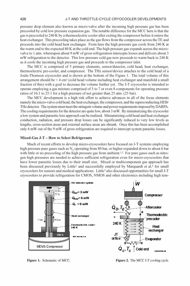
pressure drop element also known as micro-valve after the incoming high pressure gas has been
precooled by cold low pressure expansion gas. The notable difference for the MCC here is that the
gas is precooled to 240 K by a thermoelectric cooler after exiting the compressor before it enters the
heat exchanger. This precooling takes place as the gas flows from the compressor across the TE and
proceeds into the cold head heat exchanger. From here the high pressure gas cools from 240 K at
the warm end to the expected 80 K at the cold end. The high pressure gas expands across the micro-
valve to 1 atm. whereupon about 9 mW of gross refrigeration intercepts losses and delivers about 3
mW refrigeration to the detector. This low pressure cold gas now proceeds to warm back to 240 K
as it cools the incoming high pressure gas and proceeds to the compressor inlet.
The MCC is comprised of 5 primary elements, sensor/detector, cold head, heat exchanger,
thermoelectric pre-cooler, and compressor. The THz sensor/device attaches to the cold head of a
Joule-Thomson cryocooler and is shown at the bottom of the Figure 1. The total volume of this
arrangement should be < 4 cm3 (cold head volume including heat exchanger and manifold a small
fraction of this) with a goal to decrease the volume further yet. The J-T cryocooler is intended to
operate employing a gas mixture comprised of 5 to 7 or even 8 components for operating pressure
ratios of 16:1 to 25:1 for a high pressure of not greater than 25 atm. (25 bar).
The MCC development is a high risk effort to achieve advances in all of the focus elements
namely the micro-valve cold head, the heat exchanger, the compressor, and the superconducting HEB/
THz detector. The system must meet the stringent volume and power requirements imposed by DARPA.
The cooling requirements for the detector are quite low, about 3 mW. By miniaturizing the cryocooler
a low system and parasitic loss approach can be realized. Miniaturizing cold head and heat exchanger
conduction, radiation, and pressure drop losses can be significantly reduced to very low levels as
lengths, cross-section areas and external surface areas are shrunk. Once this has been accomplished
only 6 mW out of the 9 mW of gross refrigeration are required to intercept system parasitic losses.
Mixed-Gas J-T – How to Select Refrigerants
Much of recent efforts to develop micro-cryocoolers have focused on J-T systems employing
high pressure pure gases such as N2 operating from 80 bar, or higher expanded down to about 6 bar
with little or no precooling of the high pressure gas from ambient.1,2 For pure gases such as nitro-
gen high pressures are needed to achieve sufficient refrigeration even for micro-cryocoolers that
have lower parasitic losses due to their small size. Mixed or multicomponent gas approach has
been discussed previously by Little3 and successfully employed by Marquardt et al.4 for small
cryocoolers for sensors and medical applications. Little5 also discussed opportunities for small J-T
cryocoolers to provide refrigeration for CMOS, NMOS and other electronics including high tem-
Figure 1. Schematic of MCC. Figure 2. The MCC J-T cooling cycle.
426 J-t anD tHrottle-cycle cryocooler DevelopmentS
perature superconducting devices which has lead to expectations for further developments of mi-
cro-cryocoolers to meet such needs. However it has not been demonstrated for on-chip applica-
tions such as the one we discuss here until recently. New fabrication techniques borrowed from
MEMS technology were introduced by Little, Lerou, and others to pave the way for this effort.
While introducing mixed-gas approach for medical applications (cryogenic catheter) with pre-
cooling Marquardt et al. presented a novel method to design the gas mixture appropriate for specific
temperatures, efficiencies, and/or COP. This approach forms the basis of component selection
within the gas mixture. They found that by combining different components based upon their
normal boiling points (nbp) and optimizing for appropriate vapor and phase equilibriums utilizing
standard reference data from NIST6,7 combined with equations of state developed by Peng et al8: a
mixture can be designed that achieves significant increase in the maximum minimum enthalpy,
Δhmin
, compared with pure gases such as N2. It is clear from Figures 3 and 4 that gas mixture can
result in great improvements in minimum enthalpy differences over a pure fluid such as Nitrogen
for similar operating conditions. The nbp’s of Figure 4 present an interesting view toward making
component selections for a mixture. By selecting components with increased Δhmin
at key tempera-
tures we can maximize the Δhmin
for the mixture. The key is to pick just the right amount of each
component (mol % of mixture) to arrive at a mixture that gives good Δhmin
over the temperature
range of interest while remaining soluble in both vapor and liquid states for desired operating con-
ditions (pressures, temperature, flow rates, pressure drops, etc.) without separating or freezing out
individual components. We observe from Figure 5 the relationship between the solubility and
normal boiling point of some candidate mixture constituents at 75 K. It is readily apparent from
this that developing a fully soluble mixture is a delicate balancing process.
Reducing MCC Volume, aka Reducing Losses by Miniaturizing the Cryocooler
To effect a significant reduction of cryocooler size we need to look at three important aspects for J-T
cryocoolers. First of course is to consider a manner in which we may achieve higher refrigeration for a
given volume, flow rate, and/or input power. To accomplish this we need only look at the maximum Δhmin
.
Second we must consider methods for reducing the amount of refrigeration required just to cool the cryo-
cooler itself (the gross refrigeration) thereby leading to lower input powers and improved net cooling.
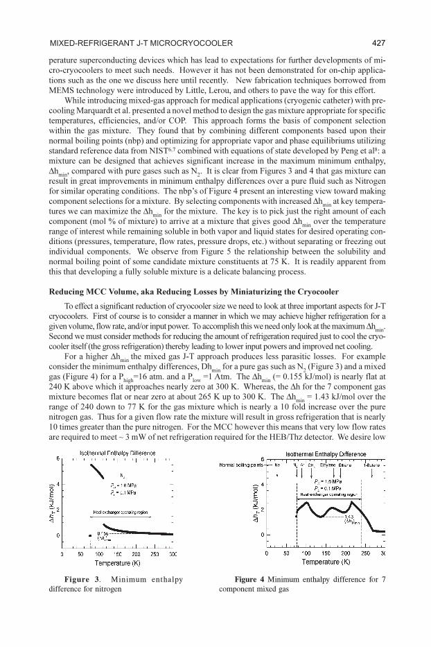
For a higher Δhmin
the mixed gas J-T approach produces less parasitic losses. For example
consider the minimum enthalpy differences, Dhmin
for a pure gas such as N2 (Figure 3) and a mixed
gas (Figure 4) for a Phigh
=16 atm. and a Plow
=1 Atm. The Δhmin
(= 0.155 kJ/mol) is nearly flat at
240 K above which it approaches nearly zero at 300 K. Whereas, the Δh for the 7 component gas
mixture becomes flat or near zero at about 265 K up to 300 K. The Δhmin
= 1.43 kJ/mol over the
range of 240 down to 77 K for the gas mixture which is nearly a 10 fold increase over the pure
nitrogen gas. Thus for a given flow rate the mixture will result in gross refrigeration that is nearly
10 times greater than the pure nitrogen. For the MCC however this means that very low flow rates
are required to meet ~ 3 mW of net refrigeration required for the HEB/Thz detector. We desire low
Figure 3 . Minimum enthalpy
difference for nitrogen
Figure 4 Minimum enthalpy difference for 7
component mixed gas
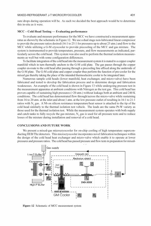
427mixeD-refrigerant J-t microcryocooler
428 J-t anD tHrottle-cycle cryocooler DevelopmentS
flow rates to achieve small low power compressors while needing high Δhmin
to meet the gross
refrigeration requirement of ~9 mW. This is determined from:
(1)
where n.
is the molar flow rate and of course Δhmin
is the minimum enthalpy difference for the
mixture. Thus we arrive at a needed flow rate of ~ 6 mmol/s (~ 0.15 std. cm3/s). From this we can
determine appropriate compressor size and flow areas for the heat exchanger, and micro-valve cold
head. Low flow rates result in small compressors with low input powers. A discussion on the MCC
compressor development is presented in an adjoining paper.9
Reducing the gross refrigeration of any cryocooler is desirable. However, for this effort it is
paramount for achieving the desired net refrigeration of 3 mW. Probably the single greatest advan-
tage to miniaturizing the MCC is in reducing losses associated with volume and area in both the
cold head and the heat exchanger. Once volume becomes low enough (on the order of less than a
1 cm3) the dominant losses become conduction and radiation. As size decreases real gains are made
to the structural aspects of the heat exchanger and cold head. Reduced size equates to increased
strength for less volume or cross-section area so we are now open to use entirely different (even
untraditional) materials than previously needed. There is of course heat exchanger ineffectiveness
and pressure drop to consider but these can be managed as they scale with size for the most part.
The HEB/Thz detector is quite small so it requires a footprint of less than 4 mm2 mostly for leads
(not the detector itself). The micro-valve cold head is sized to meet this and thus it too is quite small.
The heat exchanger, on the other hand, is somewhat larger than these and longer so it presents fairly
large section-area for both conduction and radiation. We must find a balance between the conduction
and radiation losses which also does not compromise pressure drop and heat exchanger effectiveness
too much. For low conduction we need long and thin while for low radiation we need short and thin.
For moderate flow with low pressure drop we need short, fat plus many channels while for high
effectiveness we need long with many channels. We must consider these factors and look into the
important aspect we now have moderate control over to define the appropriately small geometries and
choice of material. While MEMS fabrication techniques work very well for silicon they do not per-
form nearly as well for glass or stainless steel. It becomes quite clear from Figure 6 that silicon is a
very poor choice for the heat exchanger. Glass and stainless steel due to their low conductance on the
other hand are very good candidates although fabrication issues have to be resolved. Glass is better
yet as its conductance is about a factor of ~10 lower than of stainless steel over the 300 to 75 K
temperature range of interest. It turns out that glass fibers are manufactured in a wide range of size and
geometries small enough to be suitable for the MCC heat exchanger and provides for low conduction
loss and reduced radiation loss from the small section and perimeter area.
On-Chip Cooling — Limiting Propositions
One of the greatest limiting factors to microcryocoolers delivering on-chip cooling is the need
for high thermal isolation of the sensor/detector during operation and in quiescent modes of opera-
Figure 5. Relationship between normal boiling point and solubility for candidate mixture components.
429mixeD-refrigerant J-t microcryocooler
tion. For the MCC to provide the 3 mW of net cooling at 77 K efficiently for the HEB/Thz detector
requires a high thermal isolation to reduce background losses. Thus, it is paramount that the detec-
tor be isolated from the entire cold head including micro-valve and heat exchanger by more than
30,000 K/W. This is more than a factor of 2 greater than the 13,000 K/W previously reported by
S.-H. Lee et al.10 While analyses show this to be the case for the MCC envisioned, it is important to
demonstrate this in practice as unknowns for losses particularly from radiation and conduction are
quite sensitive to actual geometries and surface finishes. Figures 7 and 8 show a test set up to
demonstrate and measure thermal isolation of a test vehicle to simulate the cold head including
micro-valve and heat exchanger. Step 1 consists of transferring the parasitic heat radiated and
conducted from the a radiation shield (at 300 K) to the test chip (at 77 K) to the first stage of a G-M
cryocooler through an 80 um copper wire (Figure 7). Step 2 consists of calibrating the heat flow
through the copper wire by applying heat to a Nb on silicon resistance heater/thermometer on the
test chip maintained at 77 K when radiation and conduction from the shield are made zero by
maintaining the shield at 77 K also (Figure 8). Measurements were made on a test vehicle such as
the one shown in Figure 9 and found 5.1 mW of heat leak from the shield (300 K) to the chip (77 K)
for a thermal isolation (thermal resistance) of 43,700 K/W. Figures 10 and 11 show the thermal
isolation measurements and the separation of conduction and radiation losses as a function of shield
temperature. These separate into an equitable split between radiation, 2.55 mW and conduction
2.55 mW (2.41 mW through glass fiber and 0.14 mW through 25 um Pt-W leads).
As real properties such as viscosity, specific heat, enthalpy, and enthalpy difference can only
be estimated from theoretical predications, design of the heat exchanger and micro-valve for pres-
sure drops can only be estimated. While this is not too problematic for the heat exchanger, it
certainly is for the micro-valve. We simply cannot predict well what the flow rates for given pres-
Figure 6 a and b. Thermal conductivity for heat exchanger materials.
Figure 7 Thermal isolation measurement set up
Figure 8 Calibration of the thermal isolation measurement